Article

Metallic Ribbon-Core Sandwich Panels Subjected to Air Blast Loading

Department of Civil and Environmental Engineering, University of Idaho, 875 Perimeter Dr. MS 1022, Moscow, ID 83844, USA
*
Author to whom correspondence should be addressed.
Appl. Sci. 2020, 10(13), 4500; https://doi.org/10.3390/app10134500
Submission received: 4 June 2020 / Revised: 25 June 2020 / Accepted: 26 June 2020 / Published: 29 June 2020
(This article belongs to the Special Issue Advances on Structural Engineering)

Abstract

:

Featured Application

Authors are encouraged to provide a concise description of the specific application or a potential application of the work. This section is not mandatory.

Abstract

Sandwich structures provide a quite promising solution for blast alleviation techniques owing to their lightweight, high strength, and impressive energy absorption capabilities relative to solo metallic plates with equivalent density. The ability of the sandwich structure to withstand blast loading relies on its core topology. This paper numerically investigates the effectiveness of using ribbon shapes as an innovative core topology for sandwich structures subjected to blast loading. The hydro-code program (Autodyn) supported by the finite element program (ANSYS) is adopted to study the dynamic response of various sandwich panels. The accuracy of the finite element (FE) models were verified using available experimental results for a field blast test in the literature. The results show that the developed finite element model can be reliably exploited to simulate the dynamic behavior of the sandwich panels. The trapezoidal (TZ) and triangular (T) corrugated core topologies were selected to highlight the blast-resistant performance of the new ribbon core topology. Applying the ribbon topology to the traditional corrugated core topologies improved their blast performance. The facing front-plate’s deflection of the trapezoidal corrugated ribbon core sandwich structure (TZRC) has been improved by 45.3% and by 76.5% for the back-plate’s deflection, while for the triangular ribbon corrugated core (TRC), the front plate’s defection has been enhanced by 69.3% and by 112.1% for the back plate. The effect of various design parameters on the blast behavior of the Ribbon-Core Sandwich Panels (RCSPs) was investigated. A parametric study was conducted to evaluate performance indicators, including energy dissipated through plastic deformation and plate deflections. Finally, based on the parametric study, the results of this paper were recommended to be used as a guide for designing metallic ribbon sandwich structures with different protection levels.

1. Introduction

Sandwich structures are widely used in blast dissipation applications due to their excellent physical and mechanical properties [1,2,3,4,5]. They are adopted as sacrificial cladding structures, which are designed to attach at the façade of structures in order to absorb energy through the progressive plastic deformation of the front-facing plate and the inner core layer and thus the transfer of the peak force to the non-sacrificial structure can be minimized [6,7,8]. Sandwich panels are three-layer composite structures consist of two outer plates made of metals or composite materials and a crushable core layer in between. The plate faces blast wave distributes blast pressure more evenly across the core layer that deforms progressively and absorbs most of the energy, so the core has a significant influence on the blast behavior of sandwich structures. The core layer could have several topologies, such as corrugated [5,9], honeycomb [5,10], trusses [11,12], hybrid cores [13], and functionally graded cores (FGC) [14]. Under those topologies, several configurations could be used to shape the core of the sandwich panels to provide adequate stiffness and strength to support structural loads. For instance, the corrugated topology can have trapezoidal-folded, diamond-folded, Y-frame-folded, and triangular-folded core configurations [7], a zig-zag trapezoidal corrugated core [15], and woven corrugated cores [16].
A lot of research work was dedicated examining the impact of assorted core topologies on the blast performance of sandwich structures. Wei et al. [17] examined the response of metallic triangular honeycomb sandwich panels and equivalent solid plates under localized blast loads. They noticed that the sandwich panels were superior to a solid plate when subjected to blast load. Moreover, they proposed a sandwich panel with a double-corrugated soft core, which surpasses that with a triangular honeycomb core. As an attempt to investigate the effect of the core topology; Dharmasena et al. [18] examined the behavior of metallic sandwich panels with diverse core topologies; square honeycomb, triangular honeycomb, multi-layer pyramidal truss, triangular corrugation, and diamond corrugation core topologies with a core relative density of approximately 5%. They found that truss and corrugated cores had a significantly lower strength with a long plateau, like metal foams, while honeycomb cores revealed a high initial strength with a softening post peak response. Moreover, they found that crushable cores reduce the transmitted impulse by 25% compared with high rigid cores. Liang et al. [19] investigated three core topologies (square honeycomb, I-core, and corrugated) for a sandwich structure subjected to a blast load. They concluded that the best overall performance was attained by the soft cores (corrugated). Alberdi et al. [7] numerically investigated the performance of six different core topologies for metallic sandwich panels under blast loading. They concluded that folded shapes attenuate more energy than honeycomb shapes. Ahmed et al. [20] conducted a comprehensive numerical analysis on the response of metallic sandwich structures with different core configurations under the impact of blast load. They also introduced woven shapes as a novel core topology for the metallic sandwich structures. The study revealed that woven shapes achieved superior energy dissipation capability compared to the folded and honeycomb shapes; however, this novel pattern required more core relative density compared to corrugated cores.
Various research topics were focused on far-field blast; however, close-in explosions often cause a serious damage for various structural components when the explosive charge detonates at a very short distance from the structure. The American Society of Civil Engineers (ASCE) classifies explosions detonates with a scaled distance (Z) of less than 1.2 m/kg1/3 as a close-in explosion [21]. The scaled distance is defined as Z = R/W1/3, where R is the range (distance between the explosive and the target) and W is the charge weight equivalent to a TNT explosive [21]. Different from far-field explosions, blast wave released from close-in explosions could produce both localized and global failure for the structural elements. The localized failure takes place in the form of localized punching and spalling, while global failure usually occurs as flexural failure.
Field blast test is a reliable experimental approach to investigate the dynamic behavior of blast-resistant structures. Blast tests conducted in the field face many challenges, such as test setup, high cost, people injury, environmental risks, and measurement accuracy. Alternatively, finite element analysis (FEA) using hydro-code programs allows researchers to observe the response and failure modes of structural components subjected to blast loading [22]. Numerical results obtained by the FEA are usually verified by the data obtained from the field blast test. So reliable numerical models validated against measured field data is an effective tool to analyze the structural performance under blast impact. In this study, the numerical model is validated using the experimental work done by Zhang et al. [23,24]. Once the numerical model has been validated, detailed numerical models were conducted to investigate the behavior of the proposed core topology.
This paper proposes a new core topology for sandwich structures named ribbon core configuration. The purpose of this configuration is to provide a sandwich structure with many advantages, such as being very light weight, the least expensive, simplicity in manufacturing, great flexibility, and with curvature that can be built in two directions. The ribbon configuration consists of folded strips placed in two perpendicular directions forming the ribbon pattern. This technique exploits the material for a better stress distribution, which enhance the capability of the ribbon cores against blast loads. Various blast mitigation parameters such as front and back plate deflection, and energy absorption were assessed to highlight the outstanding behavior of the ribbon configuration compared with ordinary corrugated cores. A parametric study has been conducted considering design parameters such as the front plate’s thickness, back plate’s thickness, the core layer’s thickness, height of the core layer, and the angle of corrugation to investigate their influence on its blast performance.

2. Structure Configuration and Finite Element Model Validation

2.1. Geometric Description

Based on the field blast tests carried out by Zhang et al. [23,24], Figure 1 shows a typical set-up for the field blast test just before detonation. The target structures adopted for the current validation were trapezoidal (TZ) and triangular (T) corrugated sandwich panels. They consist of front, and back plates and a corrugated folded shape core layer in between made of annealed 304 stainless steel alloy. The tested panels were clamped along the four edges, providing a 288 × 300 mm2 exposure area to the shock wave, as shown in Figure 1. In the present study, only the exposure area of the panel was modeled, as the outer region of the panels was used for clamping purpose as depicted in Figure 1. The geometric parameters of the panels are demonstrated in Table 1. The blast wave was generated by the detonation of a 55 g cylindrical TNT charge located over the center of the panel with a certain stand-off distance (SoD). The SoD is the distance between the center of the explosive and the front face of the target. Here, three different SoDs of 50 mm, 100 mm and 150 mm were adopted to validate the deformation and failure mechanisms of the sandwich panel under air blast loading. The SoDs of 100 and 150 mm were used to capture the localized plastic deformation. However, the blast intensity under the SoD of 50 mm was to simulate the fracture and failure of the panel.

2.2. FE Modeling

It is a great challenge to capture the details of the structural response due to blast load through an experimental work; however, numerical investigation works well in analyzing the dynamic response of structures, especially the deformation mechanisms and fluid–structure interaction (FSI). Numerical models were conducted, and its results were compared with the experimental results for validation purposes.
In blast loading, there is an interaction between the shock wave and the target structure (FSI). Hydrodynamic codes are capable of simulating this type of interaction. In this study, the numerical simulations were performed by using ANSYS/Autodyn V-19.0. R2. It is a piece of engineering hydrocode software that is designed for solving non-linear dynamic problems such as impact, penetration and blast events using Lagrangian, Eulerian and Arbitrary Lagrange–Euler (ALE) solvers [22]. Generally, the Lagrange solver is used for modelling solid continua (structures) as the mesh move with the material as it deforms, while the Eulerian is preferable to describe the gas flow from explosion as Euler assumes that a grid is fixed in space through which material can flow. The FE model comprised the air block in which the explosion occurred and the target panel either with a Trapezoidal (TZ) or triangular (T) corrugated core suited between two facing sheets.
The computational cost for the 3D model of blast simulations is very expensive. To reduce the computational time in conjunction with maintaining accurate results, two techniques were used in this study. The first was taking symmetry advantage into consideration and only a quarter of the model was created. The second was adopting remapping, which is a perfect approach to overcome full 3D structure’s meshing problem. This technique allows a 2D model with fine mesh to be mapped into a 3D model with coarser mesh. The remapping is usually done through three steps. First, a 2D axisymmetric model was created to simulate the detonation of the explosive charge, as depicted in Figure 2a. The 2D model was run until the shock vector just arrived before striking the front face of the target. Next, a remap file has been created, and then imported to fill the 3D Eulerian domain (air block) as an initial condition, as shown in Figure 2d. Finally, the 3D model was executed to solve from that point.
The air block was only generated over the center part of the panel due to the localization of blast wave [25]. A typical air block with dimensions of 70 mm × 70 mm × 250 mm was created by the Euler solver. The boundary conditions were selected to flow out at the four faces of the air block. Thus, any pressure flowing over the structure during the blast will flow out from the boundary of the air block. A flow-out boundary was used to reduce the reflection of stress waves from the numerical boundaries back to the structure which might be considered an internal detonation problem. The sandwich structure was modeled by Belytschko-Tsay shell elements. After executing mesh sensitivity, the following element sizes were selected, 0.1 mm for 2D models, 1 mm for 3D models, and 1 mm for the shell elements. The Lagrange solver was used to model the shell elements of the structure. A fixed boundary condition was applied to the outer edges of the panel as illustrated in Figure 3. Euler elements (air) were assumed to be intersected by the Lagrange interface (structure). To deal with this interaction, a fully coupling algorithm was used to connect the Lagrange solver and Eulerian solver with a cover fraction limit of 0.5 [26]. The contact between the sandwich structural elements (face sheets and core) were considered in simulations and defined by CONTACT_AUTOMATIC_SURFACE_TO SURFACE. The contact algorithm was formulated using the penalty method, and the contact state was taken to be frictionless. Moreover, gauges were applied to the facing plates to track their response. The CPU times for the 2D simulations used to create the remapping files to fill the 3D domain for three different stand-off distances (50, 100, and 150 mm) are 5, 10 and 13 min, respectively. Most of the 3D simulations in the present study ran CPU time between 20 and 22 h.

2.3. Material Models

2.3.1. Air and TNT

To model the TNT explosion in Ansys Autodyn, the surrounding air and the product of the TNT explosion were assumed to behave like an ideal gas. An ideal gas equation of state (EOS) was used to describe air and was expressed by:
P = ( γ 1 ) ρ g e 0
where P is the pressure, γ is the ideal gas constant and equals 1.4 for air, ρ g is the air density, and e 0 is the specific internal energy. The internal energy of air was used as 2.068 × 10⁵ kJ/kg. This internal energy initialized the air medium to an atmospheric pressure of 101.3 kPa. Table 2 includes the material properties adopted for air [22].
The Jones–Wilkins–Lee (JWL) equation of state was used to describe the explosive material [27], which is in the form of:
P = A ( 1 ω R 1 V ) e R 1 V + B ( 1 ω R 2 V ) e R 2 V + ω E V
where A, B, R1, R2, and ω are empirically derived constants that depend on the type of explosives, V is the volume of charge, and E is the detonation energy per initial unit volume [28]. The material properties used for TNT were tabulated in Table 3 [28].

2.3.2. Annealed 304 Stainless Steel

The Johnson–Cook (J–C) material model was elected to describe the flow stress of the annealed 304 stainless steel. This model is ideal for a material subjected to large strains, high strain rates, and high temperatures. The flow stress model is expressed by Equation (3) [29].
σ y = [ A + B ( ε p eq ) n ] [ 1 + c ln ( ε ˙ p eq ε ˙ 0 ) ] [ 1 ( T * ) m ]
where σ y is the dynamic flow stress,   ε p eq is the equivalent plastic strain, ε ˙ p eq is the equivalent plastic strain rate, and m is the thermal softening exponent. The constants A, B, n, c, ε ˙ 0 , and m are material parameters and can be determined from an empirical fit of flow stress data. T * is the homologous temperature and it could be calculated from Equation (4).
T * = T T r T m T r
T is the material temperature; Tm is the melting temperature of the material and Tr is the room temperature. In order to capture the rupture, the failure criterion based on equivalent plastic strain was adopted. This criterion has gained popularity due to its simple and effective formulation and has been proven to provide results with satisfying accuracy [24]. Table 4 shows the J–C material model parameters for the 304 stainless steel material. A fixed boundary condition was applied to the outer edges of the panel, also gauges were applied to the facing plates to track their response.

2.4. Results and Discussion

Generally, permanent deformation/failure of the face plates is considered the most important attribute of the structural response, as all other parameters (impulse transfer and energy dissipation) rely on it. From the field blast test, it can be observed that for the 150-mm and 100-mm SoD, the face sheets plastically deformed and no failure has occurred. However, for the 50 mm SoD, the panel was damaged. Experimental and numerical central deflections of the corrugated core sandwich panels were compared and summarized in Table 5. Figure 4 shows the comparison of the deformation/failure modes of the experimental and numerical models. The comparison was focused on the permanent deflection between simulation and experiments. The differences expressed high accuracy since the standard deviation varied between 1.83% and 11.93%, as shown in Table 5. So, the numerical model was assumed with this accuracy to be able to capture and predict the deformation and failure modes for the field blast test. At this point, the proposed models can be used reliably to investigate the performance of the ribbon topology as new core configuration for sandwich structures subjected to air blast loading.

3. Proposed Sandwich Panels

Corrugated cores are stiff and strong in the longitudinal direction, but weak in the transverse direction [30]. The simplest approach to overcome this is by placing corrugated cores aligned with both the longitudinal and transverse directions of the panel. The new configuration consists of corrugated strips placed in two perpendicular directions, forming the ribbon core (RC) depicted in Figure 5. Two different geometries for RC were used in this study, the trapezoidal ribbon core (TZRC) and the triangular ribbon core (TRC). They were designed with the geometric parameters for the TZ and T cores in order to highlight the impact of the new technique on the blast performance of sandwich structures. The relative density ( ρ ) ¯ for the TZRC and TRC were 2.28 and 2.84, respectively. So, the novel topologies use a lesser amount of material compared with the traditional corrugated cores by about 64% for the TZRC and 56.9% for TRC. The width of each strip (b) was 7 mm, the height (h) was 14 mm and the thickness (tc) was 0.7 mm. The panel had the same dimensions used for the TZ and T panels. The RC structures exposed to a detonation of 55 g of TNT explosive charge located over the center of the panel with 100 mm SoD. Autodyn used to numerically investigate the dynamic response of the RC panels under the impact of the blast load.
Previous studies [14] revealed that the behavior of the sandwich structure subjected to blast load can be split into three stages, namely the fluid–structure interaction stage, core compression stage, and structural dynamic response stage. Figure 5 shows a series of deformation processes of TZRC and TRC panels subjected to the detonation of 55 g TNT with a stand-off distance of 100 mm. Figure 6 and Figure 7a show the panel at time t = 0 after remapping the final state of the 2D model to a 3D model just before the impulse is imparted to the front-face sheet of the sandwich panel. Then, at t = 0.001 msec, the shock wave firstly strikes the center of the front-face sheet. From this moment on, the front face was starting to interact with the explosive product. During the fluid–structure interaction stage, the front face obtained an initial velocity when the shock wave impinged on it, while the core and back face kept still. A dent deformation was first formed in the central area of the front face, Figure 6 and Figure 7b. Then, the high compression velocity generated by the front face induced a shock wave into the core and the core would be compressed gradually at t = 0.03 msec. It could be seen that the compression of the core decreased from the center to the peripheral region as displayed in Figure 6 and Figure 7c. During this stage, the front face was decelerated by the core while the core and the back face were accelerated. At the end of the core compression stage, the panel components obtained the same velocity and went into a phase of structural dynamic response under their own inertia. The dent deformation extended outwards and downwards with the transfer of momentum, Figure 6 and Figure 7d. Then, the panel went into an oscillation until the kinetic energy was gradually dissipated by plastic bending and stretching. Finally, at t = 10 msec, the panel underwent residual deformation as shown in Figure 6 and Figure 7e.
Figure 8 illustrates the midpoint velocity and deformation/time histories of face sheets. As exhibited in Figure 8a, the velocity at the midpoint of the front-face sheet quickly reaches its maximum value at the beginning of the response, and then gradually decreases due to core compression. The midpoint velocity of the rear-face sheet started to increase by 0.03 msec after the front-face sheet deformed, and at 0.16 msec, the midpoint velocity of the rear face sheet caught up with that of the front-face sheet. Figure 8b shows the displacement–time history of the face sheets. It can be noticed that the compression remains unchanged when the face sheets reached the same deformation velocity. Finally, the panel entered an oscillating state to disperse the residual energy.
The face sheet deformations were used as a blast performance parameter to compare between the ribbon and traditional corrugated core sandwich structures to show up the superior performance of the new core topology on the blast behavior of the structure, as shown in Figure 9. The results indicate that applying the ribbon core topology to the TZ-corrugated core improved the facing plates’ deformations by 45.3% for the front-plate deflection and 76.5% for the back-plate deflection, while for the T-corrugated core the plate defections enhanced by 69.3% for the front plate and 112.1% for the back plate. The response of the Ribbon-Core Sandwich Panel (RCSP) is in accord with the “strong core” regime defined by Liang et al. [19], which means that the ribbon cores are more efficient than ordinary corrugated cores for sandwich structures subjected to blast load. Ribbon core sandwich structures can suffer a larger impulse.

4. Parametric Study

4.1. Influence of Varying Face Sheets Thickness on RCSPs’ Face Sheets Deformations

To investigate the effect of face sheets thickness variation on the front- and back-plate deflections of RCSPs, a parametric study was performed. The TZRC sandwich structure was selected to run this study. The purpose of the parametric study is to find an effective way to enhance the blast resistance of RCSP when the equivalent density increases. The investigation of the influence of face sheets thickness variation run through two scenarios. The first one is the influence of varying the front-plate thickness on the performance of the RCSP, a constant rear-plate thickness with six different front-plate thicknesses: 0.6, 1, 1.4, 1.8, 2.2 and 2.6 mm. Figure 10 shows the effect of changing the front-plate thickness on the front and rear plates’ deflections. From Figure 10, it can be noticed that the front-layer deflection decreases upon increasing the front sheet thickness, also the back-layer deflection decreases when increasing the front-layer thickness. The results indicate that when using a front sheet with 2.6 mm thickness, the deflection decreases by an average of 75% for the front-face sheet and by an average of 70% for the rear-face sheet. It can be concluded that the rear-plate deflection decreases with increasing front-plate thickness due to the increased stiffness. In the second scenario, the effect of altering the thickness of the rear face sheet on the behavior of the RCSP is investigated by maintaining a constant front-face sheet thickness with six different rear-plate thicknesses: 0.6, 1, 1.4, 1.8, 2.2 and 2.6 mm. Figure 8 shows the effect of changing the rear-plate thickness on the deflection of the front-face sheet. From Figure 8, it can be seen that changing the rear faceplate thickness has a negligible effect on the front-layer deflection; however, the rear face sheet deflection decreases upon increasing the rear-layer thickness. Comparing the deflection when using a back layer with a 2.6-mm thickness with the deflection when using a back layer with a 0.6-mm thickness, the deflection decreases by an average of 90.6% for the rear face sheet and by an average of 19.36% for the front-face sheet. The core compression is the difference of transverse deflections between the front plate and the rear plate. It can be noticed that, by increasing the rear plate thickness, more core compression occurs due to increasing the stiffness of the core backing. So, the rear-plate thickness has a significant impact on the core compression rather than the front plate. More core compression means more efficiency for utilizing the core to get the maximum energy dissipated by the core.

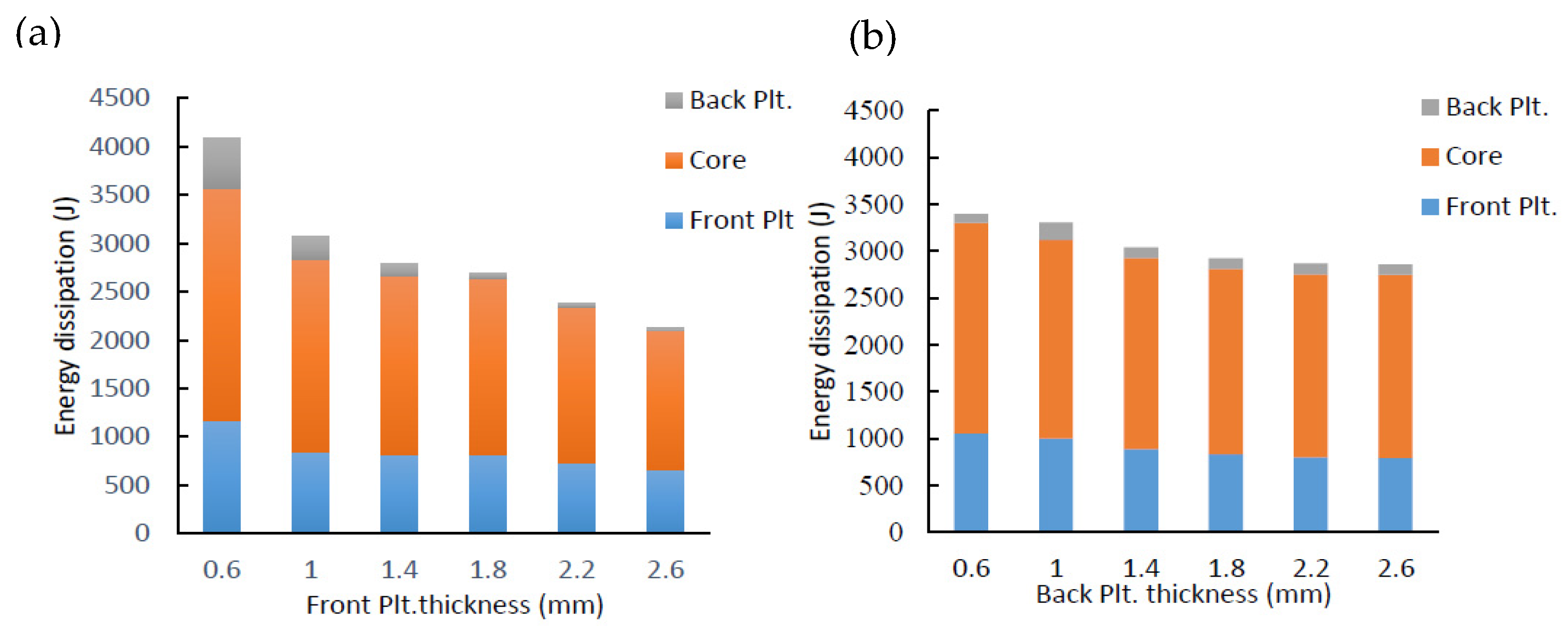
4.2. Influence of Face Sheets Thickness on Energy Dissipation

During the interaction between the explosion product and the structure, the energy of the explosion is transferred to the sandwich panel, and then dissipated through the panel deformation. The energy dissipated by each component is numerically obtained and indicated in a stack bar diagram in Figure 11. The energy dissipated by each component is essentially the difference between the total energy (ET) and initial energy (EI) of each component. Figure 11a shows the energy dissipated by each component of the RCSP for the first scenario. The figure demonstrates the contribution of the front plate, the inner core, and the rear plate in the energy dissipated by the RCSPs. The results imply that when using a front sheet with thickness of 0.6 mm the energy dissipated attain the highest value and then reduced till reaching the minimum when the front-plate thickness is 2.6 mm. It can be concluded that with increasing the front-plate thickness the energy dissipation decreases. Figure 11b illustrates the energy dissipated by the RCSP components for the second scenario. The results indicate that the rear plate has a negligible influence on the energy dissipated by the sandwich structure as the rear plate participates with a small portion in the energy dissipation of the structure relative to the other components (the front-face sheet and the inner core). The inner core layer has a major portion of the energy dissipated. Increasing the rear plate thickness boost the energy dissipation of the core layer; however, it does not enhance the total energy dissipated by the sandwich structure. The highest level of energy dissipation achieved when the front-plate thickness was 0.6 mm. Therefore, the sandwich panel with a thinner front-face sheet can improve energy-absorbing capabilities of the structure. However, under large blast loading, tearing damage may take place on the thinner front face.

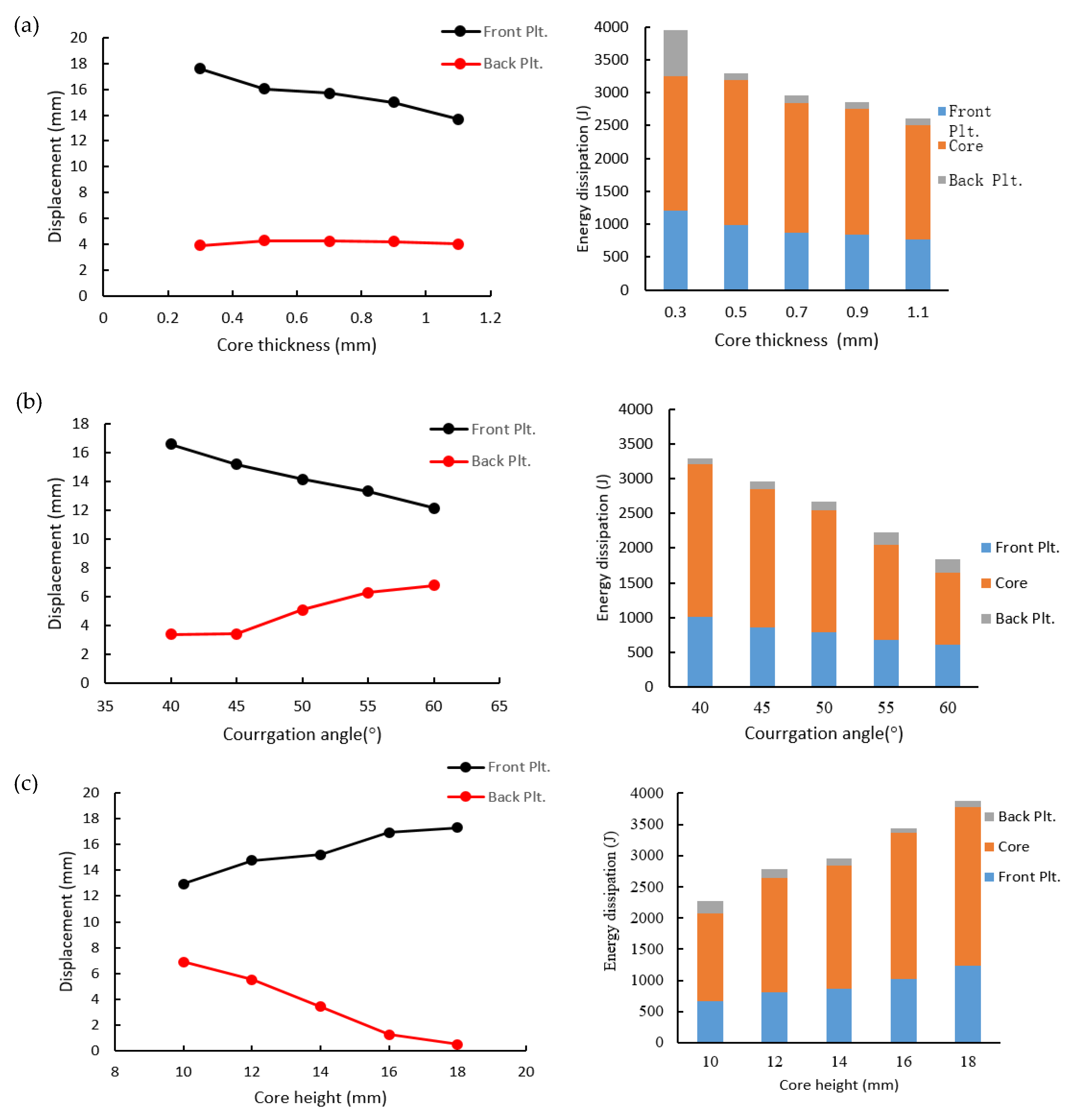
4.3. Variation of Core Parameters on the Blast Performance of the RCS

It is crucial to examine the effect of the core parameters on the blast behavior of the sandwich structure in order to maximize the protection level of the structure. The geometric parameters covered in this study were core thickness tc, the angle of corrugation ȹ (°), and core height hc. The effect of the core thickness run through varying the thickness of the corrugated ribbon core: 0.3, 0.5, 0.7, 0.9 and 1.1 mm. Figure 12a illustrates the influence of the core thickness on both facing sheet deflections and energy dissipated by the structure component due to the blast loading. It can be noticed that the front-layer deflection decreases upon increasing the core thickness; however, the back-layer deflection slightly increased. Moreover, the energy dissipated by the RCS decreased, which means that a softer core dissipates more energy. The angle of corrugation controls the behavior of the structure by increasing the corrugation angle from 40° to 60°, and the facing sheets deformations decreased by about 30% and the dissipated energy decreased by an average of 25%, as indicated in Figure 12b. The impact core height variation was also examined on the blast behavior of the TZRC sandwich structure, as shown in Figure 12c. The core height varied between 10, 12, 14, 16, and 18 mm. The results show that the core height had a significant impact on the blast performance of the structure. The deflections of the facing sheets of the sandwich structure increased by an average of 27% by increasing the core height by 40%.

5. Conclusions

The main contribution of this paper is to present a new core topology that can be applied as an inner core layer for metallic or composite sandwich structures. This study investigated the effectiveness of two different core sandwich structure topologies (folded and ribbon) for blast load attenuation. The dynamic behavior of the novel sandwich structure RCSP was investigated under air blast loading by employing a nonlinear explicit finite element simulation. The numerical model has been validated using the experimental field blast test for trapezoidal- and triangular-corrugated core sandwich panels. A good agreement was achieved by the numerical models for predicting the deformation/failure patterns for the field-tested panels with a maximum deviation of 11.93% for the back-plate defection. ANSYS/Autodyn was utilized to investigate the performance of the proposed structure under the same experimental test conditions. The blast performance of the investigated topologies was assessed in terms of the front-plate deflection, back-plate deflection, and energy dissipation. The results reveal that the ribbon core has a comparable blast resistance relative to the traditional corrugated core sandwich structures. The sandwich panel can suffer a larger impulse utilizing less amount of material compared with the traditional corrugated cores by about 64% for the TZRC and 56.9% for TRC. A parametric study was conducted to investigate the effect of design parameters on the blast performance of the novel core configuration, and the following was observed:
  • The back-plate deflection decreases with increasing front-plate thickness due to the increased stiffness. When using a front sheet with 2.6 mm thickness, the deflection decreases by an average 70% for the rear face sheet.
  • The back-plate thickness has a negligible effect on the front-layer deflection however, the back-plate deflection decreases upon increasing the back-plate thickness.
  • The sandwich panel with the thinner front-face plate could improve the energy-absorbing capabilities of the structure. However, under large blast loading, tearing damage may take place on the thinner front face.
  • Increasing the core thickness has a negative impact on the blast behavior of the structure and also increasing the angle of corrugation more than 45° reduces the efficiency of the structure under the impact of blast loading.
To conclude, the newly proposed ribbon core panels have shown superior blast performance than the traditional folded cores. The parametric study provides guidelines for designing the ribbon core sandwich structures according to the required protection level.

Author Contributions

Conceptualization, A.A.I. and M.A.; Methodology, A.A.I. and M.A.; Software, M.A.; Validation, M.A.; Formal Analysis, A.A.I. and M.A.; Investigation, A.A.I. and M.A.; Resources, A.A.I. and M.A.; Data Curation, A.A.I. and M.A.; Writing—Original Draft Preparation, A.A.I. and M.A.; Writing—Review and Editing, A.A.I. and M.A.; Supervision, A.A.I. All authors have read and agreed to the published version of the manuscript.

Funding

This research received no external funding and the APC was provided by the University of Idaho Open Access Publishing Fund.

Acknowledgments

No acknowledgment is needed.

Conflicts of Interest

The authors declare no conflict of interest.

References

  1. Wiernicki, C.J.; Liem, F.; Woods, G.D.; Furio, A.J. Structural analysis methods for lightweight metallic corrugated core sandwich panels subjected to blast loads. Nav. Eng. J. 1991, 103, 192–202. [Google Scholar] [CrossRef]
  2. Gibson, L.J.; Ashby, M.F. Cellular Solids: Structure and Properties; Cambridge University Press: Cambridge, UK, 1999. [Google Scholar]
  3. Lu, G.; Yu, T. Energy Absorption of Structures and Materials; Woodhead Publishing: Sawston, Cambridge, UK, 2003. [Google Scholar]
  4. Jing, L.; Wang, Z.; Ning, J.; Zhao, L. The dynamic response of sandwich beams with open-cell metal foam cores. Compos. Part B Eng. 2011, 42, 1–10. [Google Scholar] [CrossRef]
  5. Zhang, P.; Li, X.; Jin, T.; Wang, Z.; Zhao, L. Dynamic response of circular metallic sandwich panels under projectile impact. J. Sandw. Struct. Mater. 2017, 19, 572–594. [Google Scholar] [CrossRef]
  6. Palanivelu, S.; Van Paepegem, W.; Degrieck, J.; Reymen, B.; Ndambi, J.-M.; Vantomme, J. Close-range blast loading on empty recyclable metal beverage cans for use in sacrificial cladding structure. Eng. Struct. 2011, 33, 1966–1987. [Google Scholar] [CrossRef] [Green Version]
  7. Alberdi, R.; Przywara, J.; Khandelwal, K. Performance evaluation of sandwich panel systems for blast mitigation. Eng. Struct. 2013, 56, 2119–2130. [Google Scholar] [CrossRef]
  8. Abada, M.; Ibrahim, A. Hybrid multi-cell thin-walled tubes for energy absorption applications: Blast shielding and crashworthiness. Compos. Part B Eng. 2020, 183, 107720. [Google Scholar] [CrossRef]
  9. Li, X.; Wang, Z.; Zhu, F.; Wu, G.; Zhao, L. Response of aluminium corrugated sandwich panels under air blast loadings: Experiment and numerical simulation. Int. J. Impact Eng. 2014, 65, 79–88. [Google Scholar] [CrossRef]
  10. Liu, J.; Wang, Z.; Hui, D. Blast resistance and parametric study of sandwich structure consisting of honeycomb core filled with circular metallic tubes. Compos. Part B Eng. 2018, 145, 261–269. [Google Scholar] [CrossRef]
  11. Deshpande, V.S.; Fleck, N.A.; Ashby, M.F. Effective properties of the octet-truss lattice material. J. Mech. Phys. Solids 2001, 49, 1747–1769. [Google Scholar] [CrossRef] [Green Version]
  12. Liu, T.; Deng, Z.; Lu, T. Design optimization of truss-cored sandwiches with homogenization. Int. J. Solids Struct. 2006, 43, 7891–7918. [Google Scholar] [CrossRef] [Green Version]
  13. Cheng, Y.; Zhou, T.; Wang, H.; Li, Y.; Liu, J.; Zhang, P. Numerical investigation on the dynamic response of foam-filled corrugated core sandwich panels subjected to air blast loading. J. Sandw. Struct. Mater. 2019, 21, 838–864. [Google Scholar] [CrossRef]
  14. Jing, L.; Zhao, L. Blast resistance and energy absorption of sandwich panels with layered gradient metallic foam cores. J. Sandw. Struct. Mater. 2019, 21, 464–482. [Google Scholar] [CrossRef]
  15. Kooistra, G.W.; Deshpande, V.; Wadley, H.N. Hierarchical Corrugated Core Sandwich Panel Concepts. J. Appl. Mech. 2007, 74, 259–268. [Google Scholar] [CrossRef] [Green Version]
  16. Ahmed, S.; Galal, K. Effectiveness of FRP sandwich panels for blast resistance. Compos. Struct. 2017, 163, 454–464. [Google Scholar] [CrossRef]
  17. Wei, Z.; Deshpande, V.; Evans, A.; Dharmasena, K.; Queheillalt, D.; Wadley, H. The resistance of metallic plates to localized impulse. J. Mech. Phys. Solids 2008, 56, 2074–2091. [Google Scholar] [CrossRef]
  18. Dharmasena, K.; Queheillalt, D.; Wadley, H.; Dudt, P.; Chen, Y.; Knight, D. Dynamic compression of metallic sandwich structures during planar impulsive loading in water. Eur. J. Mech. A/Solids 2010, 29, 56–67. [Google Scholar] [CrossRef]
  19. Liang, Y.; Spuskanyuk, A.V.; Flores, S.E.; Hayhurst, D.R.; Hutchinson, J.W.; McMeeking, R.M. The response of metallic sandwich panels to water blast. J. Appl. Mech. 2007, 74, 81–99. [Google Scholar] [CrossRef] [Green Version]
  20. Ahmed, S.; Galal, K. Response of Metallic Sandwich Panels to Blast Loads. J. Struct. Eng. 2019, 145, 04019145. [Google Scholar] [CrossRef]
  21. ASCE, Blast Protection of Buildings: ASCE/SEI 59-11. 2011. Available online: https://sp360.asce.org/PersonifyEbusiness/Merchandise/Product-Details/productId/232616700 (accessed on 4 February 2020).
  22. Autodyn, T. Theory Manual Revision 4.3; Century Dynamics Inc.: Concord, CA, USA, 2003. [Google Scholar]
  23. Zhang, P.; Liu, J.; Cheng, Y.; Hou, H.; Wang, C.; Li, Y. Dynamic response of metallic trapezoidal corrugated-core sandwich panels subjected to air blast loading–An experimental study. Mater. Des. (1980–2015) 2015, 65, 221–230. [Google Scholar] [CrossRef]
  24. Zhang, P.; Cheng, Y.; Liu, J.; Wang, C.; Hou, H.; Li, Y. Experimental and numerical investigations on laser-welded corrugated-core sandwich panels subjected to air blast loading. Mar. Struct. 2015, 40, 225–246. [Google Scholar] [CrossRef]
  25. Yuen, S.C.K.; Langdon, G.; Nurick, G.; Pickering, E.; Balden, V. Response of V-shape plates to localised blast load: Experiments and numerical simulation. Int. J. Impact Eng. 2012, 46, 97–109. [Google Scholar] [CrossRef]
  26. Autodyn, A. Theory Manual Revision 4.3; Century Dynamics: Concord, CA, USA, 2005. [Google Scholar]
  27. Zukas, J. Introduction to Hydrocodes; Elsevier Science: Amsterdam, The Netherlands, 2004. [Google Scholar]
  28. Dobratz, B.M. Properties of Chemical Explosives and Explosive Simulants; Dobratz, B.M., Ed.; California University, Livermore (USA), Lawrence Livermore Lab: Livermore, CA, USA, 1972.
  29. Lee, S.; Barthelat, F.; Hutchinson, J.; Espinosa, H.D. Dynamic failure of metallic pyramidal truss core materials–experiments and modeling. Int. J. Plast. 2006, 22, 2118–2145.S. [Google Scholar] [CrossRef]
  30. Xiong, J.; Du, Y.; Mousanezhad, D.; Eydani Asl, M.; Norato, J.; Vaziri, A. Sandwich Structures with Prismatic and Foam Cores: A Review. Adv. Eng. Mater. 2019, 21, 1800036. [Google Scholar] [CrossRef] [Green Version]
Figure 1. Schematics of (a) an experimental set-up, (b) trapezoidal (TZ)-panel cross-section unit cell, and (c) triangular (T)-panel cross-section unit cell (reproduced from refs. [23,24]).
Applsci 10 04500 g001
Figure 2. Remapping blast pressure from a 2D model to a 3D model. (a) The 2D model before detonation. (b) The pressure contour of the 2D model before striking the target. (c) The pressure vectors of the 2D model before remapping. (d) The pressure contour of the 3D model after remapping just before hitting the structure.
Applsci 10 04500 g002
Figure 3. Three-dimensional FE models for the sandwich structures. (a) TZ-panel. (b) T-panel.
Applsci 10 04500 g003
Figure 4. Comparison between the experimental and numerical results of deformation/failure modes due to detonation at stand-off distances (SoDs) of 50, 100, and 150 mm. (a) TZ-panel. (b) T-panel.
Applsci 10 04500 g004
Figure 5. Schematic and inner core configuration of the ribbon core sandwich structures. (a) Trapezoidal corrugated ribbon core (TZRC)-panel. (b) Triangular ribbon corrugated core (TRC)-panel.
Applsci 10 04500 g005
Figure 6. Dynamic response of the TZRC.
Applsci 10 04500 g006
Figure 7. Dynamic response of the TRC.
Applsci 10 04500 g007
Figure 8. (a) Velocity and (b) displacement–time histories for the facing sheets at midspan. (c) Enlarged view for displacement–time histories within (0–0.25 msec) time interval, TZRC (left column) and TRC (right column).
Applsci 10 04500 g008
Figure 9. Residual midspan deflections for the facing sheets of sandwich structures with different core configurations under the impact of detonation of 55 g TNT at SoD 100 mm.
Applsci 10 04500 g009
Figure 10. Central deformation with the face sheets thicknesses variation.
Applsci 10 04500 g010
Figure 11. Energy dissipation for Ribbon-Core Sandwich Panel (RCSP) components with variation of (a) front-plate thickness. (b) Back-plate thickness.
Applsci 10 04500 g011
Figure 12. Facing sheets mid-span deflection and energy dissipation For RCSP components with variation in (a) core thickness, (b) the angle of corrugation and (c) core height.
Applsci 10 04500 g012
Table 1. Parameters of the sandwich panels.
PanelExplosiveGeometric Parameters
SoD (mm)W (g)tf (mm)hc (mm)tc (mm)tb (mm)B (mm)ȹ (°) ρ ¯ (%)
TZ-150551.38140.71.387456.34
TZ-2100551.38140.71.387456.34
TZ-3150551.38140.71.387456.34
T-150551.38140.71.38-456.6
T-2100551.38140.71.38-456.6
T-3150551.38140.71.38-456.6
* data from Zhang et al. [23,24].
Table 2. Ansys/Autodyn material model for the air.
EOSγReference Density (g/cm3)Reference Energy (μJ/mg)
Ideal gas1.41.225 × 10−3 2.068 × 10⁵
Table 3. The JWL model used to define the TNT material model in Ansys/Autodyn.
ρ     ( g / cm 3 ) A (GPa) B (GPa) R 1 R 2 ω
1.63373.753.7474.150.900.35
Table 4. Constitutive model of 304 stainless steel adopted in Ansys/Autodyn.
ParameterUnitValue
Reference densityg/cm37.85
EOS-Linear
Bulk moduluskPa1.67 × 108
Strength-Johnson Cook
Shear moduluskPa6.69 × 107
Yield stress, AkPa3.10 × 105
Hardening constant, BkPa1.00 × 105
Hardening, exponent, n-0.65
Strain rate constant, c-0.07
Ref. strain rate, ε ˙ 0 s−11.00
Thermal softening exponent, m-1.00
Indoor temperature, TmK292
Melting temperature, TrK1672
Failure-Plastic strain
Plastic strain-0.42
Table 5. Experimental and numerical results.
PanelFront-Plate Deflection δf (mm)Discrepancy (%)Back Plate Deflection δb (mm)Discrepancy (%)
Experimental *NumericalExperimental *Numerical
TZ-1FailureFailure-FailureFailure-
TZ-228.8929.421.8314.1414.643.54
TZ-318.9920.558.217.698.216.76
T-1FailureFailure-FailureFailure-
T-222.7124.708.7610.3111.5411.93
T-312.9114.119.315.185.638.69
* data from Zhang et al. [23,24].

