Article

Real Geometrical Imperfection of Bow-String Arches—Measurement and Global Analysis

1
Department of Structures and Bridges, Faculty of Civil Engineering, University of Žilina, Univerzitná 8215/1, 010 26 Žilina, Slovakia
2
Department of Geodesy, Faculty of Civil Engineering, University of Žilina, Univerzitná 8215/1, 010 26 Žilina, Slovakia
3
Department of Structural Mechanics and Applied Mathematics, Faculty of Civil Engineering, University of Žilina, Univerzitná 8215/1, 010 26 Žilina, Slovakia
*
Author to whom correspondence should be addressed.
Appl. Sci. 2020, 10(13), 4530; https://doi.org/10.3390/app10134530
Submission received: 5 June 2020 / Revised: 25 June 2020 / Accepted: 26 June 2020 / Published: 30 June 2020
(This article belongs to the Special Issue Advances on Structural Engineering)

Abstract

:
In order to analyse the buckling behaviour of existing bow-string arch bridges, it is necessary to deal with the imperfections that influence the global stability of their superstructures. Direct quantification of the material imperfections represents an extremely difficult task for this type of structure. On the other hand, the geometrical imperfections can be measured in more detail by using special scanners or high-accuracy surveying instruments. This contribution represents a beginning part of the research activities focusing on the real values of geometric imperfections of existing steel arch bridges using three-dimensional (3D) scanning. The possibility of using these data for further theoretical and numerical analysis based on the finite element method (FEM) and for further creating the building information modelling (BIM) of the bridges is proposed. When verifying the stability of bow-string arch bridges, much higher attention has to be paid to the out-of-plane stability of the arches. The numerical models of an existing bridge superstructure were developed to execute a nonlinear analysis with geometrical imperfections included. Both the theoretical and actual imperfections obtained by 3D scanning were taken into account. The obtained data, their comparison and the applicability of the presented method are finally discussed.

1. Introduction

Arch bridges are mainly used for bridges of medium and larger spans. In Slovak conditions, arch bridges are mainly used as arches stiffened by a tensioned beam, since they are architecturally suitable for bridging wide water courses or flat valleys. They are therefore proposed in cases where the construction depth is limited and wider spans need to be bridged than are usually allowed by truss bridges, and where the application of cable-based bridge systems is either uneconomical or inappropriate because of their lower rigidity. The disadvantages of these bridges include the more laborious manufacture and demanding construction of the bridge with the complicated assembly of large spans. The individual parts of the arch bridge with well-designed parameters are relatively slim. In order to improve the stability of the compression arch, depending on the height of the traffic area, upper truss or frame bracings are often proposed as well. Especially in the case of narrow bridges, the difference between the efficiency of the truss and frame bracing is small [1]. The arch stability in the direction perpendicular to its plane is greatly aided by the rigidity of the arch connection to the tie-beam [2].
In the global analysis of structures with low stability, the effects of second order theory and imperfections should be taken into account. The imperfections for the global analysis of beam structures should be chosen to take into account both in-plane and out-of-plane buckling, including torsional buckling with symmetric and asymmetric buckling shapes in the most unfavourable direction and form. For arch bridges with the bottom beam serving as a tie chord, this requirement is often reduced to verify only the stability of the arches out of their plane. In contrast to a deck-arch bridges, where the vertical columns act destabilizing to arches, the buckling length in the plane of the bow-string arch is controlled by usually vertical ties (hangers), as was proved by calculations using numerical models.

2. Imperfections

2.1. Application of Imperfections in Bridge Arch Analysis

The use of arch member models opens the way for the use of calculation according to the second order theory with specified imperfections also in commonly available commercial software. So, if a more sophisticated approach is needed, the imperfections should be incorporated directly into the global arch bridge models. For local imperfections, the equivalent initial deformation of the members in the shape of sinusoid or quadratic parabola are defined in EN 1993-1-1. Initial global imperfections due to the inclination of frame systems can also be applied in the analysis of the bowstring arches, especially in the case of rigid hangers, or as imperfections of vertical or inclined portals. However, the full consideration of local and global imperfections in the global analysis puts great demands on the complexity of the computational model and cause difficulties in entering imperfections. Therefore, the method where the second order effects are taken into account, partly through global analysis and partly through the individual assessment of the members, is now more widely used.
Alternatively, the assumed shape of the global and local imperfections may also be derived from the shape of the elastic buckling mode of the structure in the considered plane. The advantage of this procedure is that the first buckling mode of the structure can be calculated. It represents the most effective initial shape of the deformation. Moreover, this procedure presented by the authors of [3,4] can be advantageously incorporated into the computer programs. The so-called unique global and local imperfection is calculated by a stability calculation within the global analysis. However, the use of shapes of critical buckling modes of the structure as equivalent imperfections encounters the problem of determining the amplitudes of buckling modes [5,6,7]. In the case of a spatial structure subjected to compression and biaxial bending, but structurally designed such that the buckling in one of the planes is minor, the authors of the paper [8] have already proposed a procedure for calculating the amplitude of the imperfection in the dominant plane. This procedure was used by the authors of [9] for their analyses and comparisons. To date, the most comprehensive approach in this area was probably presented in the works of authors [10,11], which extend the knowledge of applying unique global and local imperfections to more complex spatial tasks taking into account not only flexural buckling but also the lateral torsional buckling.
However, the aforementioned works deal with theoretical analysis using design equivalent geometric imperfections. Works where real imperfections would be included and a comparison of their impact on the loss of the out-of-plane stability of the arch are not available. For this reason, it is necessary to identify the real geometric imperfections of the arches on real bridge objects and to analyse their influence on the stability and resistance of arches [12]. Then, the outputs of these measurements should be applied into the geometrically and materially nonlinear analyses (GMNIA) of spatial arch bridges with imperfect arches by introducing real geometric and structural imperfections. Alternatively, the geometrically nonlinear analyses (GNIA) of these systems can be executed with equivalent geometric imperfections derived from measured deformations and scaled to reflect both real geometrical and structural imperfections, respectively.

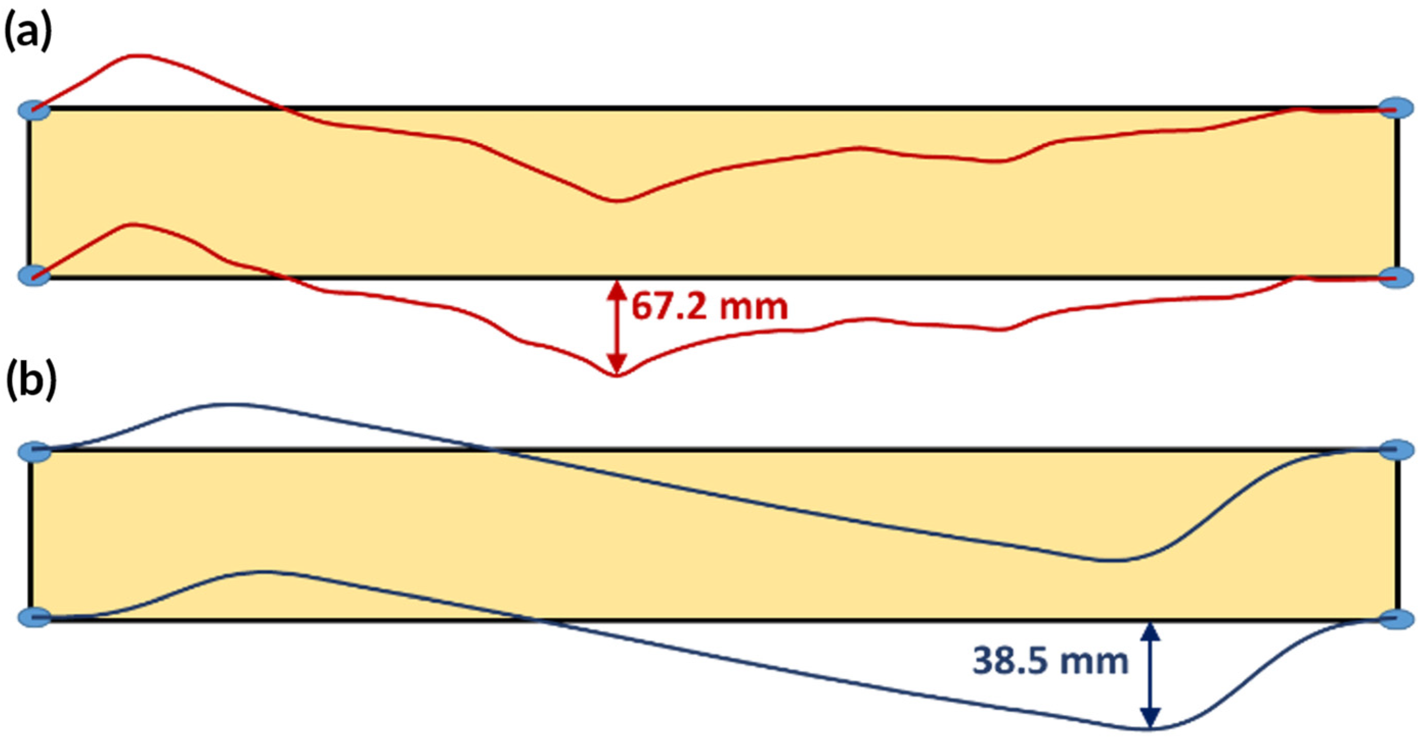
2.2. Innovative Geometric Imperfections Measurement

Various methods can be used to measure the geometric shape of the arch. At present, one of the most commonly used method for accurate surveying and detailed digitization of terrain or objects is laser scanning using a 3D laser scanner [13]. Therefore, data collection of real geometric imperfections by laser 3D scanning of arch bridges is proposed in this paper.
The laser scanning belongs to non-contact, quick and accurate geodetic observation methods with a highly detailed output. It is a modern progressive method that has found wide application in many engineering areas during last years, [14]. The measurement is in principle the creation of a numerical model from a physical object. The result of the 3D scanning is a point cloud, which has to be processed by the most time-consuming process of geodetic activity. As arch bridges are objects with a length of the order of tens of meters, 3D laser scanning provides sufficient accuracy possibilities and it can be implemented in place quickly and without affecting the flow of traffic on the bridge or underneath. The use of this modern method and subsequent data evaluation using specialized software can provide valuable information on the applicability of this method for imperfection measurement. At the same time, it will reveal their hidden possibilities for further use in creating BIM of bridge structures, so necessary for operations using modern technologies in the not so distant future.

2.3. Comment on the Structural Imperfections

With regard to the complex solution of the problem, the research should also focus on the experimental determination of the real values of structural imperfections within the cross-sections of the arches. In the case of this structure, the most important structural imperfections are the residual stresses in the structural steel due to its heat treatment, rolling and mainly welding. This issue has been investigated by scientists for several decades [15] and there are still new studies specifying the estimated value of residual stresses, or discussing their numerical modelling, e.g., works [16,17,18]. However, the aim of this paper is to point out the possibilities of the alternative consideration of geometric imperfections. Thus, the results below are specifically focused on the imperfections of geometric nature only.

3. Pilot Study

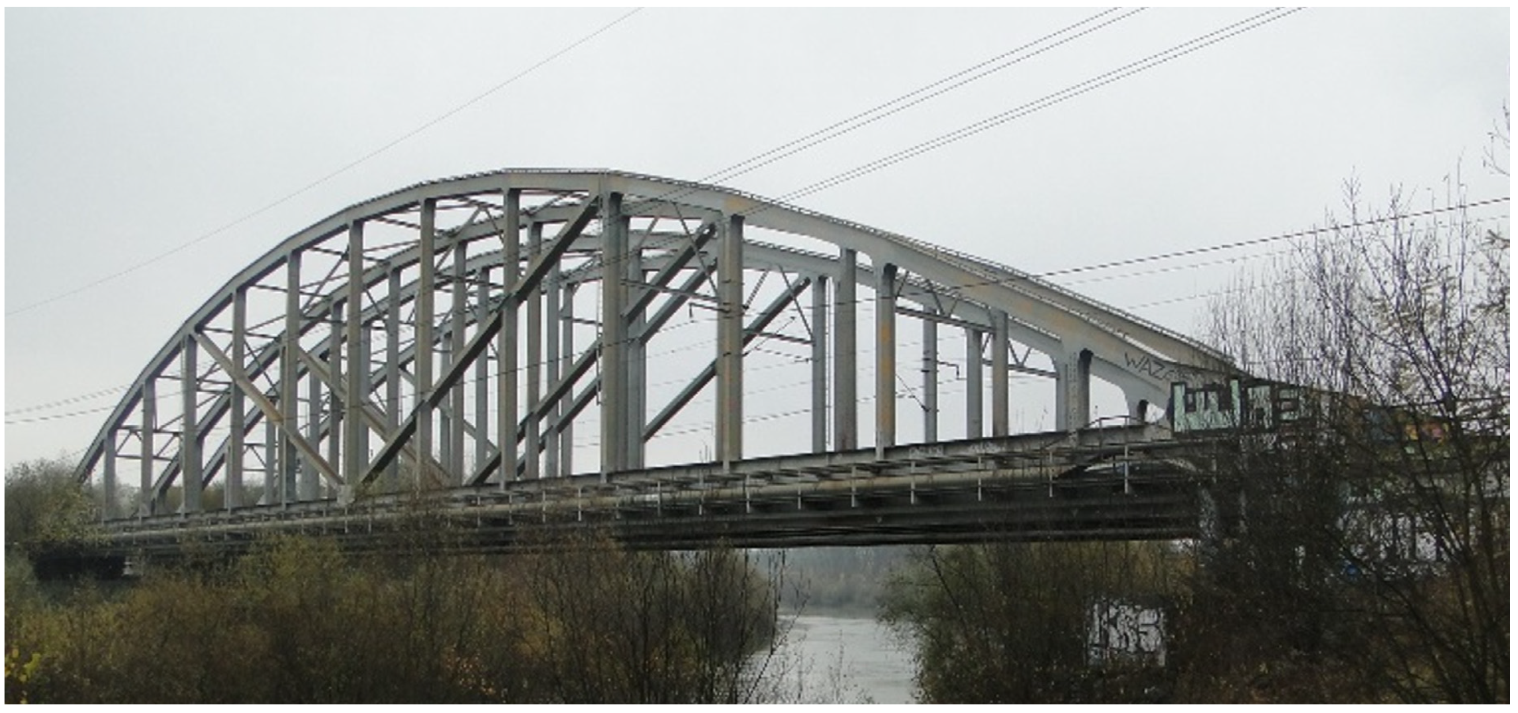
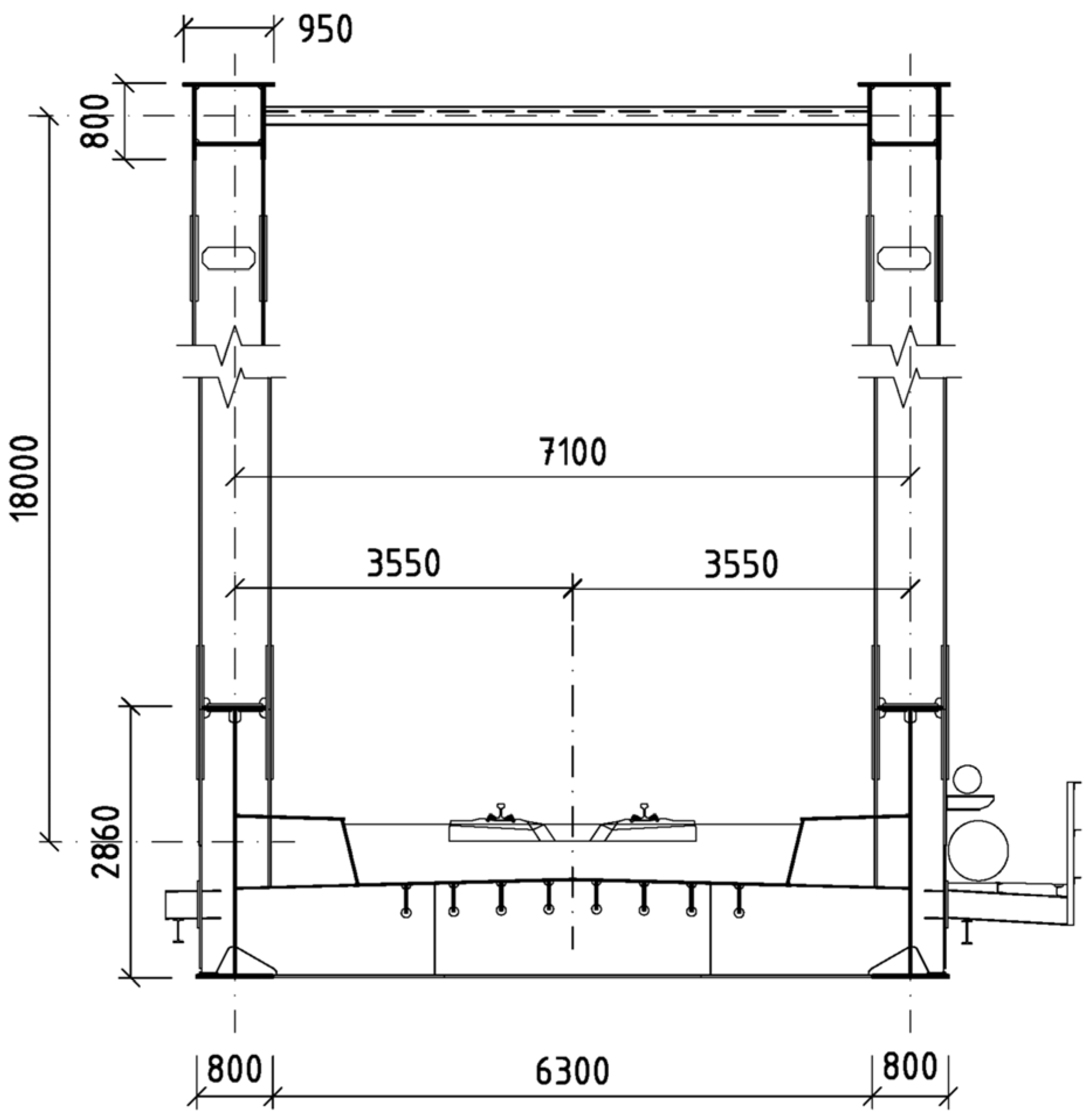
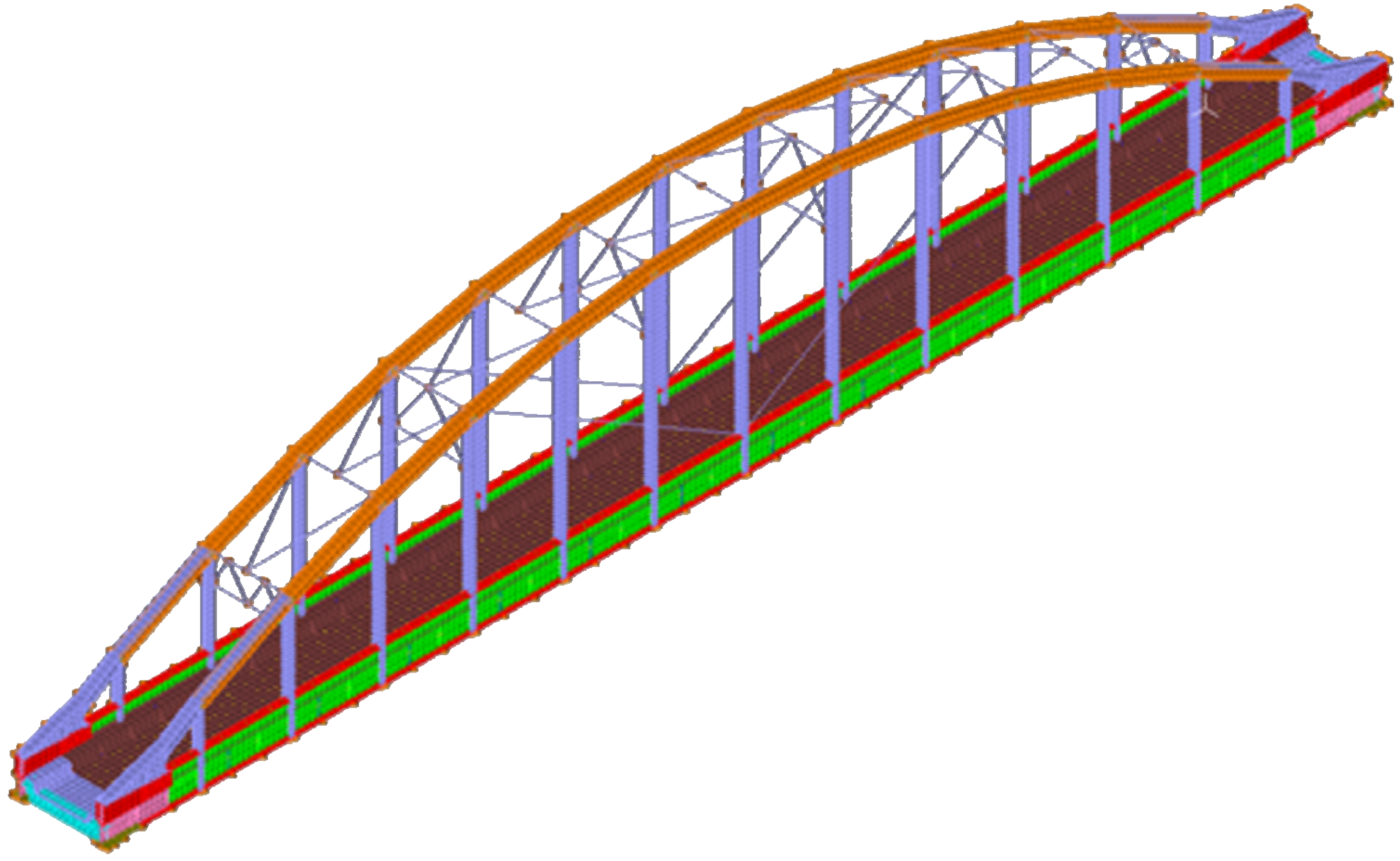
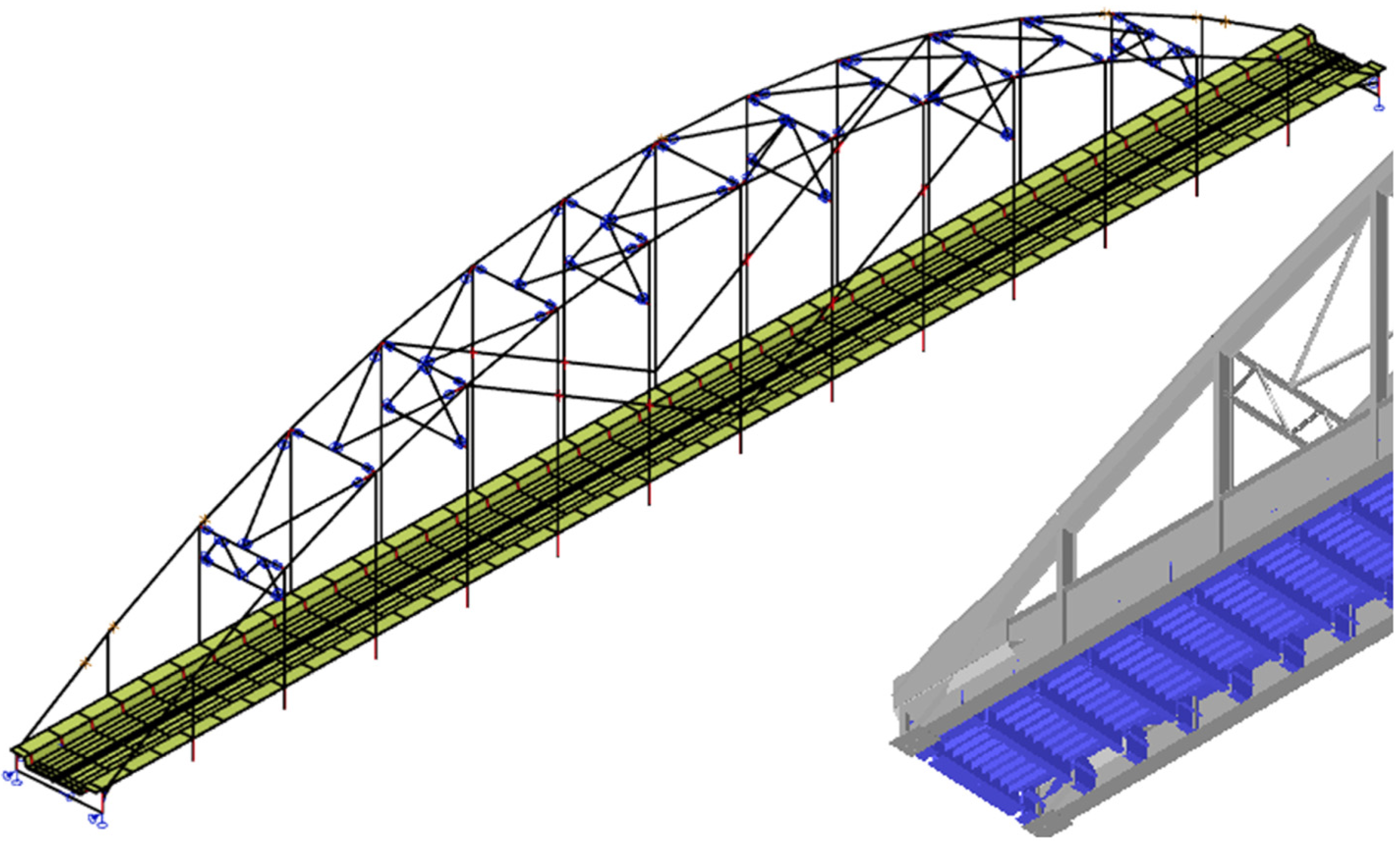
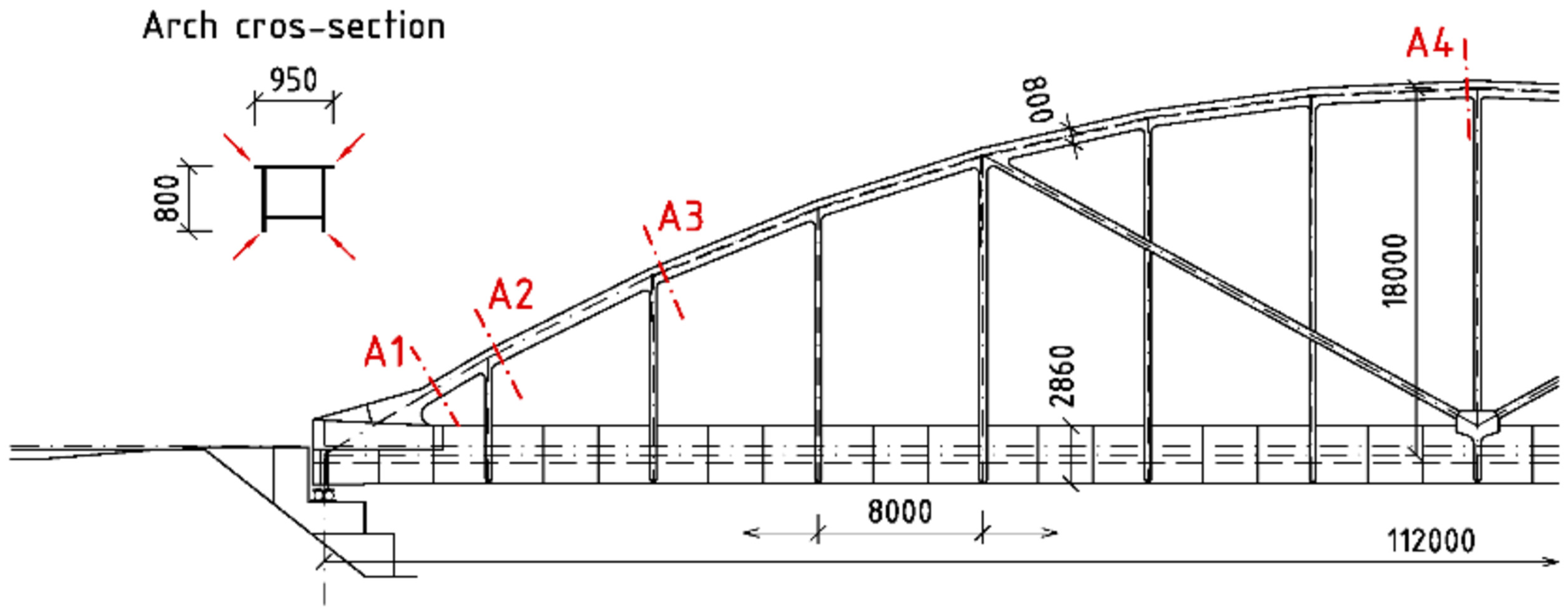
3.1. Selected Bridge
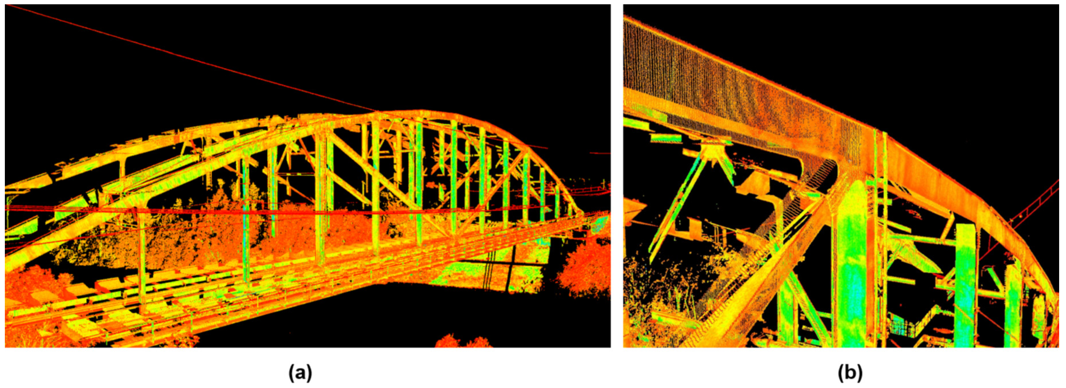
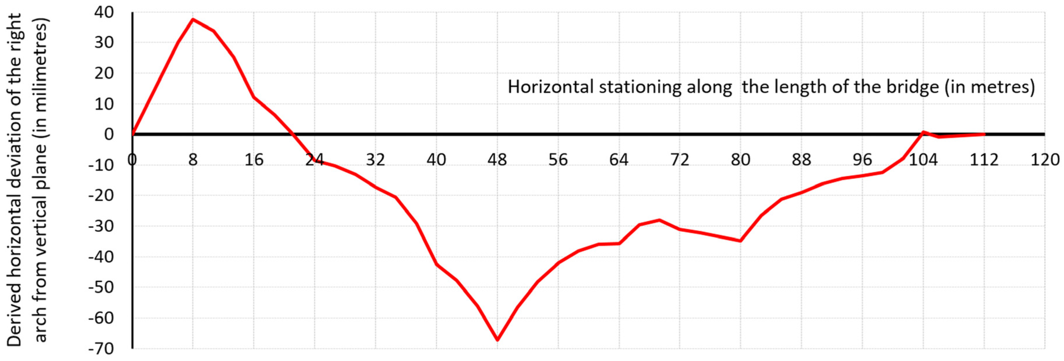
The first arch bridge scanned in detail was the railway bridge over the Váh river near Žilina town. The bridge shown in Figure 1 was built in 2000 on the main Slovak railway line as two separated bow-string arch superstructures for each line.
Each main superstructure consists of two steel bow-string girders with a theoretical span length of 112.0 m in an axial distance of 7.1 m. Bottom steel orthotropic deck forms the support for continuous ballast bed. The plate girders are designed from opened symmetrical I-shaped cross-sections of a constant height of 2860 mm almost the entire length of the bridge. The arch has a theoretical rise of 18 metres and it has a rectangular box cross-section with an inner clear dimension of 700 × 600 mm. All the hangers (as well as the diagonals situated between the fourth and seventh hangers) have welded I-shaped cross-sections. The upper truss bracings of the arches are made of hot-rolled sections. Cross-section of the right superstructure is visible in Figure 2.
The bridge structure was at the beginning of the research subjected to a thorough diagnostic inspection focusing on checking dimensions, degradation and possible damages.

3.2. Laser Scanning

The Leica ScanStation C10 laser scanner was used to measure the geometrical shape of arches of the chosen bridge structure. The device has a guaranteed range of 300 m, a field of view of 360° × 270°, a scan speed of 50,000 pps and a scan density adjustable from 1 × 1 mm in the overall range. In the case of the presented measurement of the arch, the accuracy for the side edges of the arch cross-section of 2–3 mm could be obtained. Anyway, several complications occurred when scanning the arches. Worse reflective properties of the dirty coating led to more measurement stands. Another problem during the scanning was the poor accessibility of the measured bridge, because of the watercourse, untreated vegetation and terrain. It was also impossible to place the stands directly on the bridges, as all the measurements ran at full traffic operation. The scanning resulted into a group of mutually non-referenced scans, and the first task was to cross-reference each other. The resulting 3D model presented in Figure 3 did not need to be neither recalculated to absolute the coordinates nor georeferenced, so the resulting model was created in a relative coordinate system. Based on the recorded shape and position of the arch, the differences from the designed position can be derived.
For example, Figure 4 shows the identified value of the horizontal deviation of the arch axis from the vertical plane.

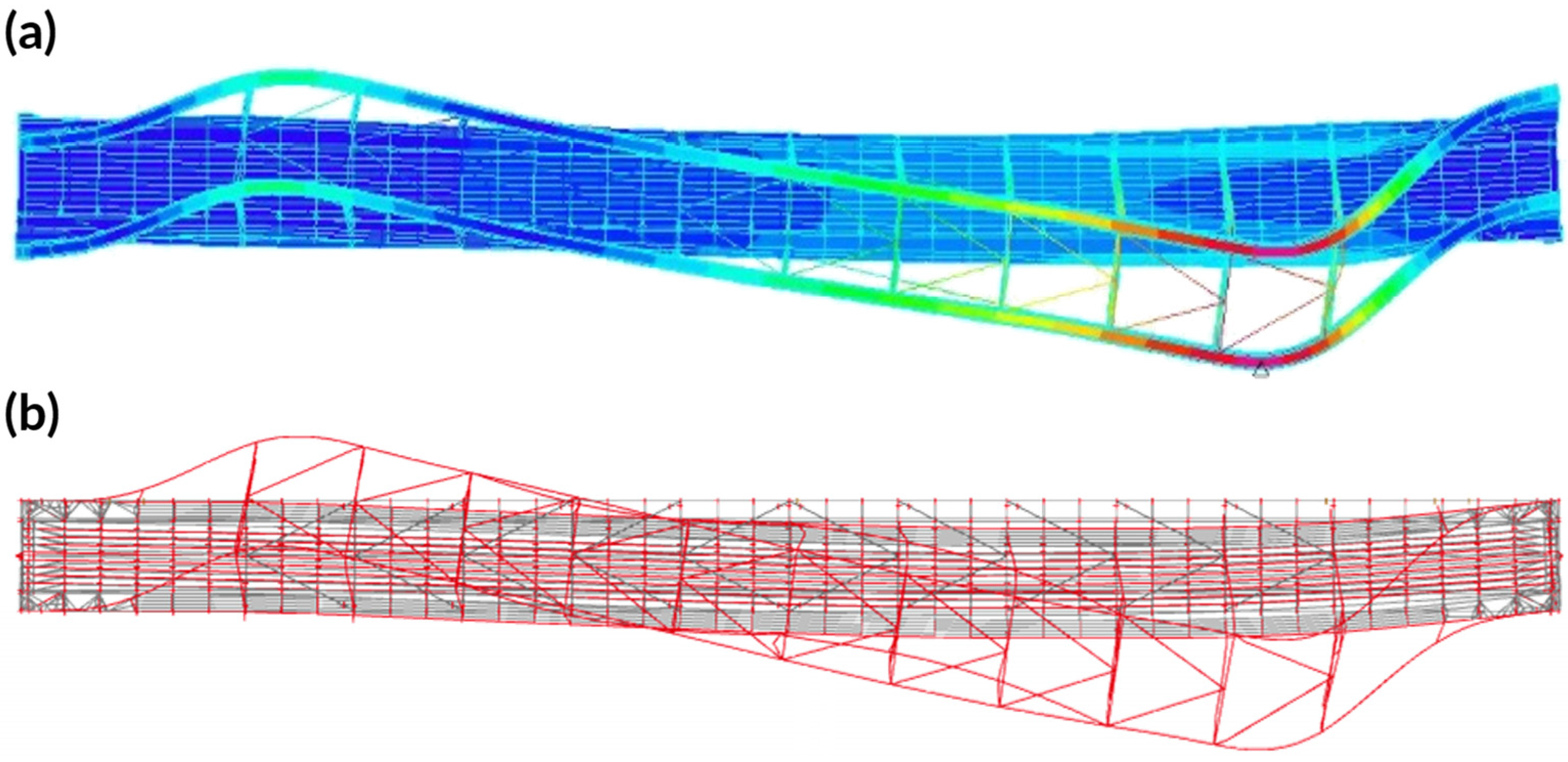
3.3. Finite Element Method Analyses

Numerical global analyses were executed by using of finite element method (FEM). Two programs and two different approaches concerning the mesh of the main superstructure were applied.
The first spatial numerical model was created in ADINA software (ver. 9.4.2, Adina R&D, Inc., Watertown, MA, USA, 2019). Almost all the parts of the bridge superstructure including the orthotropic deck were modelled within this model by shell finite elements (Figure 5). The beam elements were assumed only for upper bracings and for the diagonals between the hangers as well. The changes in thicknesses of each modelled 2D member were carefully taken into account in accordance with the bridge documentation and in situ verification. Special attention was paid to the approximation of the arch-to-girder connection, where all the relevant eccentricities, stiffeners and additional ribs were precisely considered.
The second 3D model was developed in the SCIA Engineer software (ver. 19.1, SCIA nv, Hasselt, Belgium, 2019) widely used in civil engineering practice. Contrary to the first one, almost all the parts of the bridge superstructure were modelled by 1D finite elements (Figure 6) in this model. Shell elements were applied only for the plate of the orthotropic deck, but the longitudinal and transversal stiffeners of the deck were modelled as ribs of the shell elements again. Within this model, all the eccentricities of the modelled members and all the changes in the thicknesses of the plates were taken into account as well.
The FEM models were loaded by the same dead loads and also by Load Model 71 (LM71) including the dynamic effects in accordance with EN 1991-2. In addition to the consideration of the actual position of the railway track, the code-based eccentricity of vertical loads produced by the unequal load of train wheels was thought as well. Corresponding partial safety factors and combination rules were applied to create a design combination of loads. The longitudinal position of the LM71 came from the checking process as a crucial element for the normal stresses in the outer arch, which is affected by the compression combined with biaxial bending. Basis static values such as the sum of the mass, the reactions, deformations, etc. were compared between the models, to make sure that the static behaviour of both models was similar.
Naturally, the linear analyses (LA) were done first in both software. The linear stability analysis (LSA) were also ran in order to get the first eigenmode of the loss of the arches’ structural stability, see Figure 7. This structural buckling mode is quantified by the minimum load factor αcr to reach the global instability, by which the design load has to be increased to cause the loss of stability.
In order to see the influence of real imperfections on the internal forces and stresses in linear approach, a real shape of the arches was implemented into the geometry of the models. Therefore, the analysis executed on such imperfect models can be designated as a linear analysis with the real geometric imperfections included (LIRGA).
The geometrically nonlinear analyses with the imperfections included (GNIA) of both spatial models of the bridge superstructure was the next step. By introducing the “real geometric imperfections” into the nonlinear analysis, taking into account second-order effects, an influence of the deformed shape on the static behaviour of the structure were correctly estimated. As imperfection was taken from the laser scanning, the results of this analysis will be designated as GNIRGA. The scheme of axis of arches with real geometrical imperfections are in Figure 8a.
The last analysis came from the discussion on the comparison of the effect of the measured real geometric imperfections with the results taking into account the geometric imperfections reflecting the normatively determined tolerances. Such an analysis can be then designated as geometrically nonlinear analyses with theoretical geometric imperfections were included (GNITGA). With reference to the statements given in the introduction of this paper, for the shape of such theoretical imperfections, the first mode of the loss of stability can be utilised. Thus, the supposed shape of the global and local geometric imperfections were considered in the form of the first elastic buckling mode of the arch structure. The key problem is to estimate the amplitude of this kind of unique global and local imperfection (see designation “ugli” imperfection in [5]). As the presented research deals with geometrical imperfections only, the so-defined imperfection in this paper does not represent an equivalent geometrical imperfection, which should also include structural imperfections. Therefore, it will subsequently be referred to as a “theoretical geometrical imperfection”. Hence, the amplitude scaling of the bucking shape was based on the allowances in tolerances for bridges given in EN 1090-2.
Simplistically, the value of the maximum horizontal displacement of the arch from its designed position was estimated as a sum of the global and local deviation from straightness. For the local deviation, the value of Lloc/750 was considered, but not less than 6 mm. Similarly, for the global tolerance, Lglob/500 was assumed, with a limit value of at least 12 mm. The first mode of out-of-plane stability reaches its maximum between the 11th and 12th hangers, therefore the local length Lloc = 8.96 m was taken, while for the “global” scale, the buckling length of the arch calculated by LSA was adopted, i.e., Lglob = 13.28 m. Thus, the amplitude of theoretical geometrical imperfection in the shape of the first out-of-plane buckling mode in this GNITGA analysis was the sum of the local and global tolerances 12.0 + 26.5 = 38.5 mm. The scheme of the axis of arches with theoretical geometrical imperfections are presented in Figure 8b

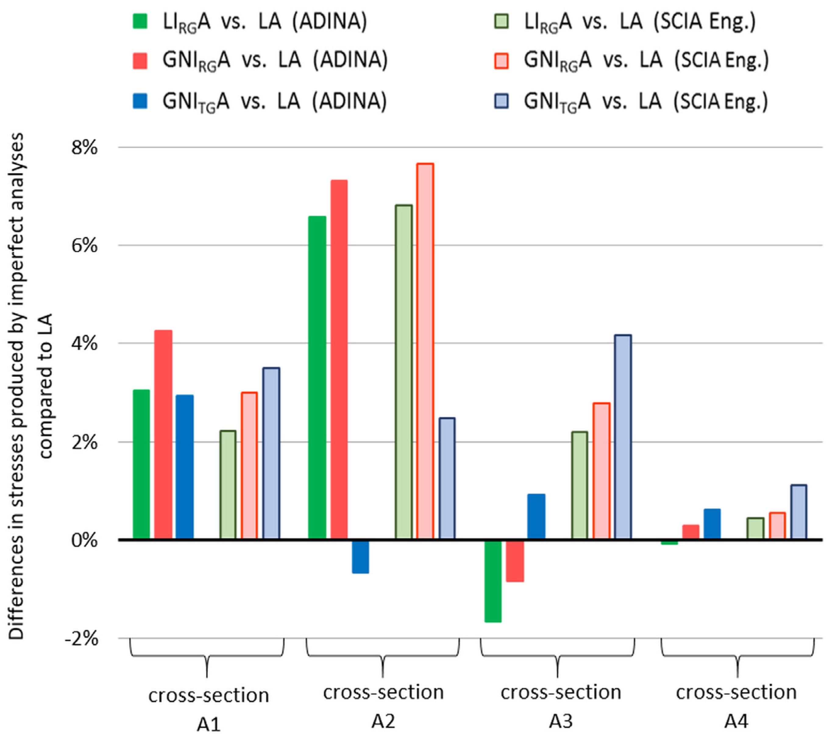
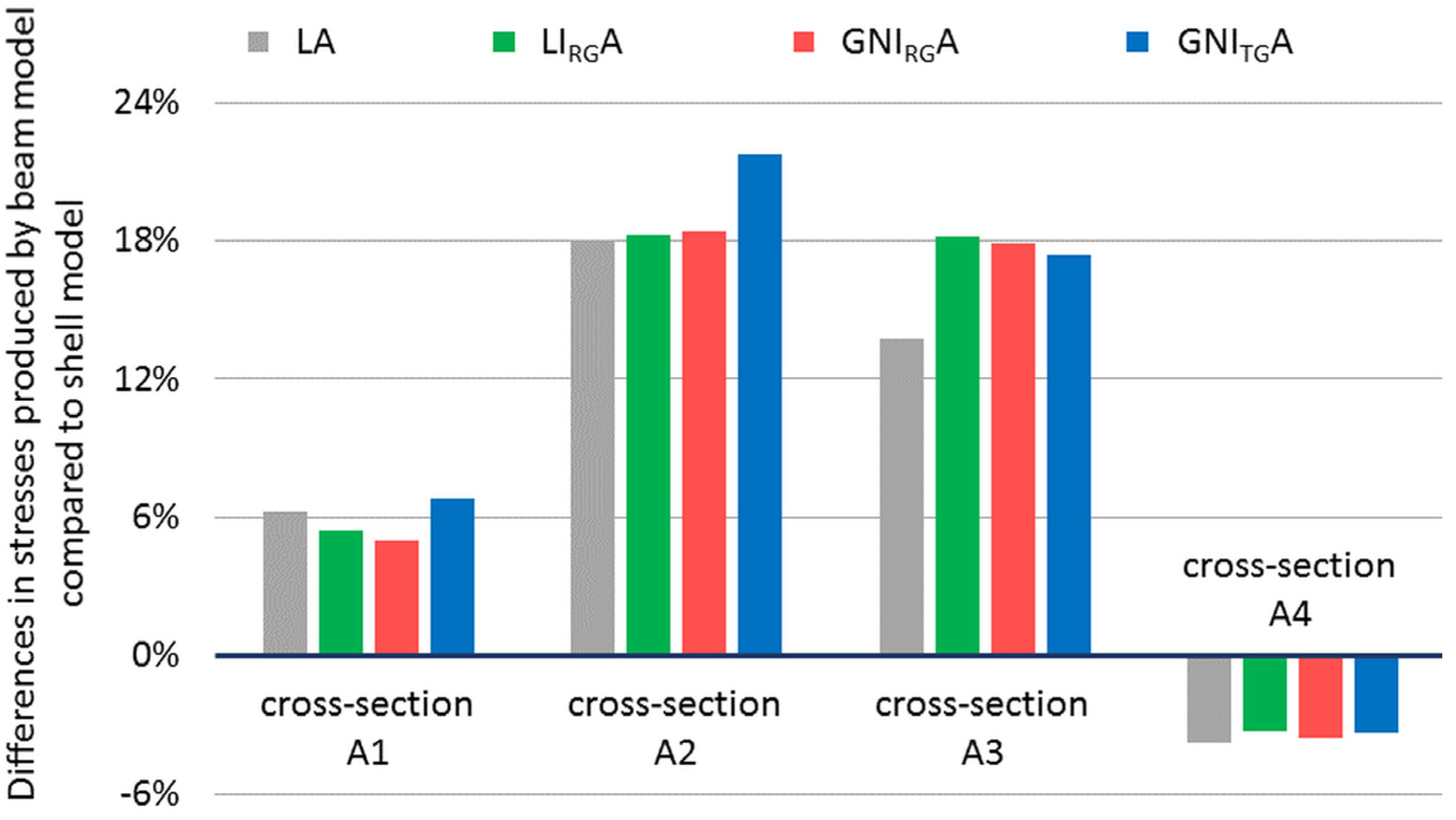
3.4. Comparison of Results

Some results from the presented study are compared in Table 1. Maximum stresses in four chosen cross-sections of the right arch are compared. The values in Table 1 were found as the maximum stresses picked from the FEM analyses at the same corner point of each arch cross-section marked in Figure 9 from A1 to A4.
From the comparison it can be stated that geometric imperfections had a smaller influence on the stresses than expected. The consideration of the measured imperfection produced stresses not far from analyses, where the theoretical geometrical imperfections derived from the allowed tolerances were taken into account.
The graph in Figure 10 shows a percentage increase in stresses in the analyses with imperfections included in comparison with linear analyses without any imperfections (LA). Except for the differences between both software analyses, only a few percent of effect is evident. Surprisingly, the linear analyses with the real geometrical imperfections included (LIRGA) were very close to their more complex geometrically nonlinear alternative (GNIRGA).
The absolute values of differences are small, but relative variation between the four chosen arch cross-sections is evident. The real deformation can be sometimes very different from the theoretical shape of buckling, thus it could probably better reflect the increase in stresses in the most affected cross-sections. However, if the values are compared, it can be clearly seen that the geometrical imperfection influenced stresses only slightly in the case of this bridge.
At the same time, it has to be pointed that almost three times higher differences were produced by the application of the different FEM model than by the different type of analysis. Such a comparison is given in Figure 11, where the percentage differences in the stress obtained by the SCIA Engineering model are presented in comparison to the stresses produced by the analyses in the ADINA software.
In the cross-sections near the arch foot and in the middle of the span the difference are smaller. The influence of using 2D versus 1D finite elements, respectively, is evident even though both the models acted statically very similarly in global comparison. For instance, the differences in the calculated deformations (deflections) between the models were only about 1%.

4. Discussion and Conclusions

The comparison of several analyses executed in two different software indicates the relative small influence of geometric imperfection on the stress state of arches of considered, from a 112-metres-span bow-string arch bridge. Nevertheless, this study shows that taking into account geometric imperfections can produce more relevant results. The comparison of the stresses, if either real or theoretical imperfections were taken into account, shows the influence of the considered shape of geometrical imperfection. Basically, in the same cross-section of the arch, a nonlinear analysis can produce stress values that are higher or lower than those obtained by the linear analysis, depending on the initial shape of imperfection.
The other task is the type and precision of the FEM model, especially the application of the type and size of finite elements, the modelling of structural details, and the approximation of connection, bearings, etc. As mentioned above, the presented two different approaches produced differences in the stresses in some cross-sections up to 22%, while the effects of taking into account geometrics imperfections in geometrically nonlinear analysis were much smaller. Of course, this conclusion cannot be automatically generalised.
The present study pointed out the possibility of applying laser scanning during the inspection or diagnostic of existing bridges. The obtained data can be subsequently used for relevant analyses when assessing arches or the entire bridge superstructure. Whether the second order nonlinear analyses are to be applied or the simplified method is used, (e.g., by the means of a so-called equivalent column method), the information about the actual imperfection are certainly valuable data for a possible refinement of the results, [19,20]. In the case of bridges, the consideration of real imperfections can lead into a better determination of its load-carrying capacity.
Scanning using the 3D laser scanner seems to be a relatively convenient and unpretentious method for obtaining basic data about the real geometric imperfections of steel bridge arches. In order to collect much more data, enhanced measurement was started and today is almost finished. Two tenths of the arch bridges have been already scanned and now the attention is paid to more sophisticated data processing and comparison methodology.

Author Contributions

Conceptualization, J.O.; data curation, M.F. and J.C.; formal analysis, J.O., and J.K.; investigation, M.F. and J.C.; methodology, J.O. and J.G.; supervision, J.O.; validation, J.O., J.G. and M.F.; visualization, J.O. and M.F.; writing—original draft preparation, J.O.; writing—review and editing, M.F. and J.G. All authors have read and agreed to the published version of the manuscript.

Funding

This research was supported by Research Project No. 1/0336/18 of the Slovak Grant Agency.

Conflicts of Interest

The authors declare no conflict of interest.

References

  1. Vičan, J.; Odrobiňák, J.; Gocál, J. Recently designed bow-string railway bridges in Slovakia. In Proceedings of the 7th International Conference on Arch Bridges (ARCH 2013), Split, Croatia, 2–4 October 2013; pp. 427–434. [Google Scholar]
  2. Vičan, J.; Odrobiňák, J.; Gocál, J.; Hlinka, R. Design of the two-line railway bridge with the longest span in Slovakia. In Proceedings of the 8th International Conference “Bridges in Danube Basin”, Timişoara, Romania, 4–5 October 2013; pp. 267–278. [Google Scholar]
  3. Chladný, E.; (Slovak University of Technology, Bratislava, Slovakia). Comments to EN 1993-1-1: Draft 2000. Comments sent to J. Brozetti, accepted by G. Sedlacek from TC 250/SC3, CEN Brussels. Personal Communication, 2000. [Google Scholar]
  4. Baláž, I. Determination of flexural buckling resistance of frames with members with non-uniform cross-sections and non-uniform axial compression forces. In Proceedings of the 34th Slovak Meeting of Experts on Steel Structures, Pezinok, Slovakia, 16–17 October 2008; pp. 17–22. [Google Scholar]
  5. Baláž, I.; Koleková, Y. Structures with UGLI imperfections. In Proceedings of the 18th International Conference “Engineering Mechanics 2012”, Svratka, Czech Republic, 14–17 May 2012; pp. 61–86. [Google Scholar]
  6. Chladný, E.; Štujberová, M. Frames with unique global and local imperfection in the shape of the elastic buckling mode (Part 1). Stahlbau 2013, 82, 609–617. [Google Scholar] [CrossRef]
  7. Chladný, E.; Štujberová, M. Frames with unique global and local imperfection in the shape of the elastic buckling mode (Part 2). Stahlbau 2013, 82, 684–694. [Google Scholar] [CrossRef]
  8. Chladný, E.; Chladná, M. The application of initial bow imperfection in the designs of new Danube Bridges in Slovakia. In Proceedings of the 4th International Conference “Bridges across the Danube”, Bratislava, Slovakia, 13–15 September 2001; pp. 179–184. [Google Scholar]
  9. Vičan, J.; Odrobiňák, J.; Gocál, J. Analysis of out-of-plane stability of bow-string arches. Communications 2016, 18, 3–9. [Google Scholar]
  10. Aguero, A.; Pallares, L.; Pallares, F.J. Equivalent geometric imperfection definition in steel structures sensitive to lateral torsional buckling due to compression. Eng. Struct. 2015, 96, 41–55. [Google Scholar] [CrossRef]
  11. Aguero, A.; Pallares, L.; Pallares, F.J. Equivalent geometric imperfection definition in steel structures sensitive to flexural and/or torsional buckling due to compression. Eng. Struct. 2015, 96, 160–177. [Google Scholar] [CrossRef]
  12. Farbák, M.; Chromčák, J.; Jošt, J. Meranie reálnych geometrických imperfekcií na oceľových oblúkových mostoch/Measurement of real geometric imperfections on steel arch bridges. In Proceedings of the 43th Slovak Meeting of Experts on Steel Structures, Bešeňová, Slovakia, 16–17 October 2013; pp. 47–52. [Google Scholar]
  13. Ižvoltová, J.; Pisca, P.; Koťka, V.; Mancovič, M. 3D laser scanning of railway line. Communications 2013, 15, 80–84. [Google Scholar]
  14. Ižvoltová, J.; Villim, A.; Kozák, P. Determination of geometrical track position by robotic total station. Procedia Eng. 2014, 91, 322–327. [Google Scholar] [CrossRef] [Green Version]
  15. Alpsten, G.A.; Tall, L. Residual Stresses in Heavy Welded Shapes. Weld. Res. Suppl. 1970, 49, 3–105. [Google Scholar]
  16. Gkatzogiannis, S.; Knoedel, P.; Ummenhofer, T. Simulation of welding residual Stresses—from theory to practice. In Mathematical Modelling of Weld Phenomena 12; Verlag der Technischen Universität Graz: Graz, Austria, 2019; pp. 383–400. [Google Scholar]
  17. Szalai, J.; Papp, F. On the probabilistic evaluation of the stability resistance of steel columns and beams. J. Constr. Steel Res. 2009, 65, 569–577. [Google Scholar] [CrossRef]
  18. Young, B.W. Residual Stresses in Hot Rolled Members; Iabse Reports of the Working Commissions; Ein Dienst der ETH-Bibliothek: Zürich, Switzerland, 2019; 15p, Available online: https://www.e-periodica.ch/cntmng?pid=bse-re-001:1975:23::41 (accessed on 29 June 2020).
  19. Prokop, J.; Vičan, J. Pinned-fixed beam-column resistance verification according to European standards. Civ. Environ. Eng. 2018, 14, 28–36. [Google Scholar] [CrossRef] [Green Version]
  20. Koubova, L.; Janas, P.; Markopoulos, A.; Krejsa, M. Nonlinear analyses of steel beams and arches using virtual unit moments and effective rigidity. Steel. Compos. Struct. 2019, 33, 755–765. [Google Scholar]
Figure 1. Photo of the selected bow-string arch bridge.
Applsci 10 04530 g001
Figure 2. Cross-section of the right bridge superstructure in the middle of the span.
Applsci 10 04530 g002
Figure 3. A point cloud as a result of the 3D laser scanning: (a) the global view; (b) in detail.
Applsci 10 04530 g003
Figure 4. Derived horizontal deviation of the right arch from the vertical plane.
Applsci 10 04530 g004
Figure 5. Finite element method (FEM) model in ADINA with the shell finite elements applied to most parts.
Applsci 10 04530 g005
Figure 6. Finite element method (FEM) model in SCIA Engineering with most parts as beam finite elements.
Applsci 10 04530 g006
Figure 7. Shape of the first buckling mode of arches obtained by: (a) the ADINA “shell” model αcr = 6.0; and (b) the SCIA Engineer “beam” model αcr = 6.2.
Applsci 10 04530 g007
Figure 8. Horizontal displacement of the arch axis in the assumed global geometric imperfection used in FEM analyses: (a) the real geometric imperfection based on the data obtained from the 3D laser scanning; (b) the theoretical geometric imperfection in the form of the first buckling mode with the amplitude scaled on the basis of allowed tolerances.
Applsci 10 04530 g008
Figure 9. Side view of the bridge with the designation of the four selected arch cross-sections, where the stresses were analysed (dimensions in millimetres).
Applsci 10 04530 g009
Figure 10. Percentage differences in the stresses produced by the analyses with the imperfections included (LIRGA, GNIRGA and GNITGA) compared to the simple linear analysis (LA).
Applsci 10 04530 g010
Figure 11. Percentage differences in the stresses produced by the common “beam” model in the SCIA Engineer compared to the more complex “shell” model in ADINA.
Applsci 10 04530 g011
Table 1. Maximum corner stresses in the selected arch cross-sections.
Arch Cross- SectionDominant Elements/SoftwareType of FEM Analysis
LALIRGAGNIRGAGNITGA
A1shells/ADINA−190.8−196.6−198.9−196.4
beams/SCIA Eng.−202.7−207.2−208.8−209.8
A2shells/ADINA−181.5−193.5−194.8−180.3
beams/SCIA Eng.−214.2−228.8−230.6−219.5
A3shells/ADINA−183.6−180.5−182.0−185.3
beams/SCIA Eng.−208.8−213.4−214.6−217.5
A4shells/ADINA−186.1−185.9−186.6−187.2
beams/SCIA Eng.−179.0−179.8−180.0−181.0

