1. Introduction
Off-road machines and industrial stationary applications have a huge growth potential with respect to energy savings. Their duty cycle often requires large output power and machine robustness to handle such working loads. In conventional systems, low efficiency is mainly caused by an internal combustion engine (in heavy mobile applications), hydraulic rotational machines, long hoses, and throttling losses of valves to transfer mechanical power to the actuator. In order to improve these drawbacks, a combination of electric and hydraulic technology is an option, considering the high efficiency, reduced noise, and the absence of local emission in electric components [
1].
The combination of electric and hydraulic components in a closed circuit defines the concept of electro-hydrostatic actuator systems (EHAs). These systems are a compact and reliable self-contained unit composed of an electric motor, pump/motor, and hydraulic cylinder. EHAs can be driven utilizing three different configurations: Fixed displacement pump and variable speed electrical motor, variable displacement pump and fixed speed motor, and both variable. The latter can provide the highest energy efficiency, however, the cost is higher and it requires more complex control systems in order to achieve maximum efficiency regardless of the hydraulic operation point [
2,
3].
After all, the concept based on the fixed displacement pump and variable speed electrical motor can offer the lowest manufacturing costs, simplicity, and high efficiency. Though it has a slower dynamic response [
2,
4]. Several studies have shown the capacity of fixed-displacement pumps being used for distinct applications. An EHA with vane pump is presented in [
5] for industrial applications and the virtual prototype represented an effective tool to evaluate the energy consumption in injection molding machines. In [
6], an axial-piston pump reaching efficiencies up to 60% during actuation is reported and in [
7], an internal gear pump is applied in a high-speed power unit for mobile applications. Aside from the pump working principle, in [
8] the authors provided a review of electro-hydraulic technology and presented different circuit configurations for EHA using differential cylinders applications.
Differential cylinders are mostly employed in construction machines due to requirements of output force and installation space. When these actuators are utilized, the inflow and outflow are not balanced, affecting the accuracy in the actuator position, control performance, and energy efficiency.
Flow compensation methods were previously explored, most of them utilizing pilot-operated check-valves [
9,
10], and shuttle valves [
11]. In [
12], the influence of hydraulic accumulator to compensate the flow mismatch between cylinder areas and pump displacement on energy efficiency in an open-loop circuit is investigated. Regarding the configurations of pump-controlled systems for differential cylinders, a review and classification is given in [
13].
The usage of EHA systems in differential cylinders has been studied extensively, considering the wide possibilities of system configuration and components. This work investigates the performance of a system without implementing the flow compensation method, only relying on the external gear pump/motors available in the market (off-the-shelf), reducing costs.
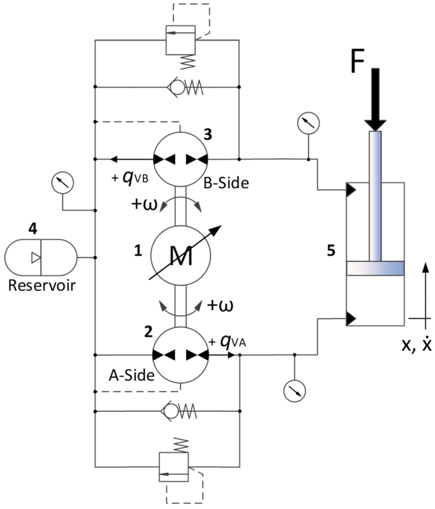
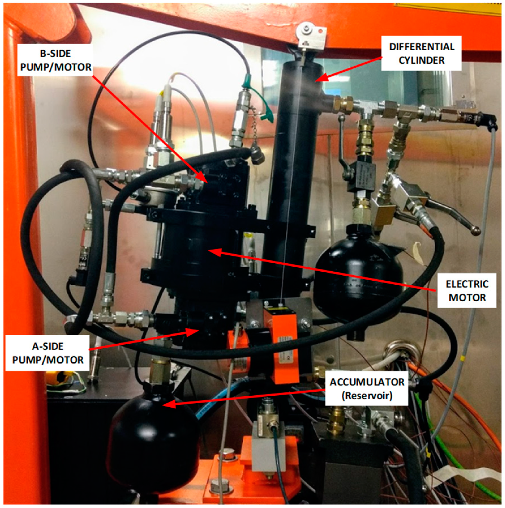
This paper proposes a circuit layout using two fixed displacement pump/motors driven by one variable speed electrical motor, controlling a differential cylinder in closed circuit operation mode. The system behavior and the energy efficiency are analyzed regarding the flow balance between volumetric displacements of the pump/motors and cylinder areas. The influence of the pressure dependent pump/motor’s leakages on balancing the pump/motors and cylinder is discussed and additional hydraulic components are included in order to avoid cavitation and overpressure. The analysis is carried out by simulation using a mathematical model validated through experimental tests. A stand-alone crane setup is utilized in order to test the compact EHA for mobile and stationary applications.
The following section introduces the setup utilized, followed by the mathematical model. After that,
Section 4,
Section 5 and
Section 6 present results obtained by simulation and experimental data, discussion, and finally conclusions can be found at the end of the paper, respectively.
3. Mathematical Model Description
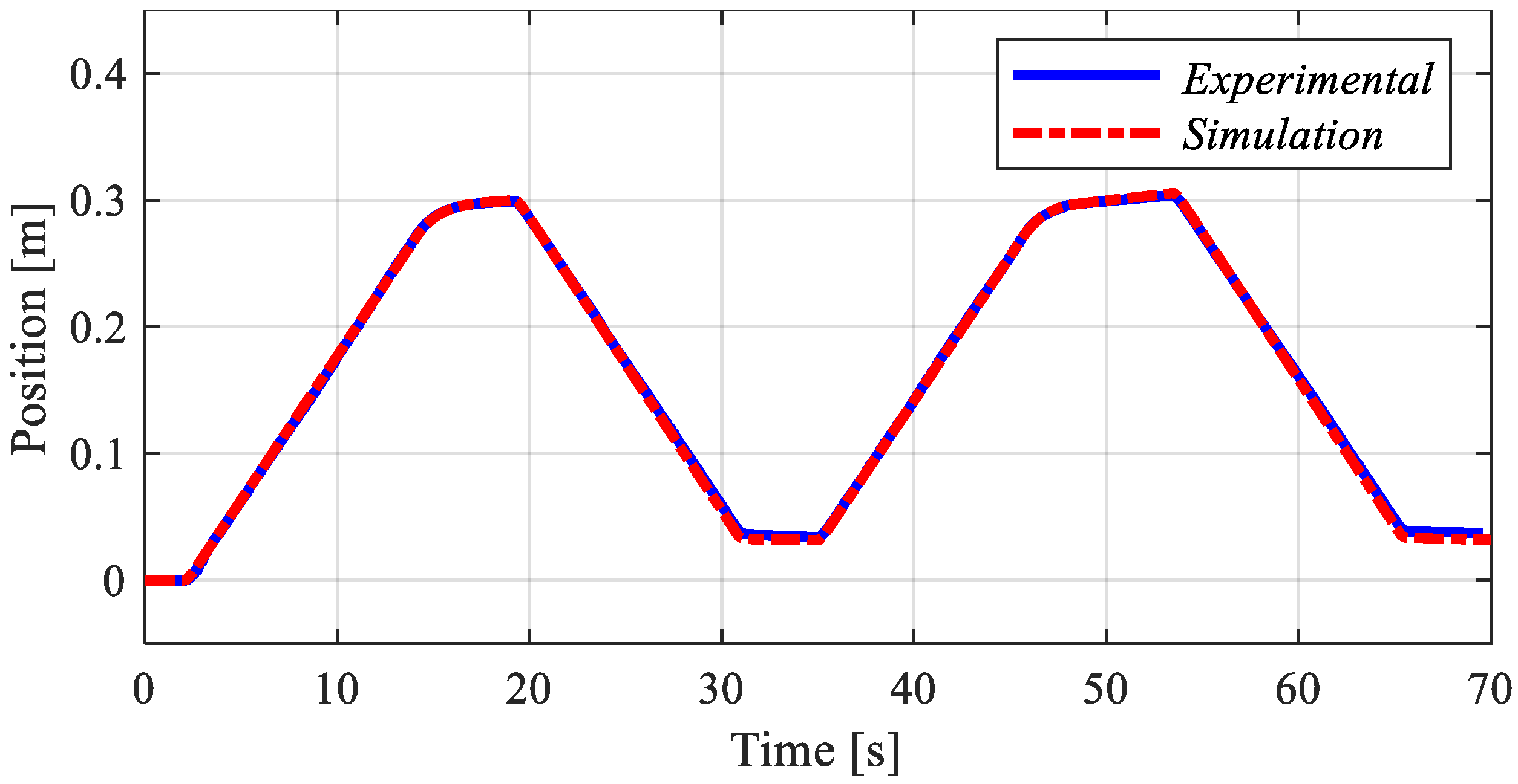
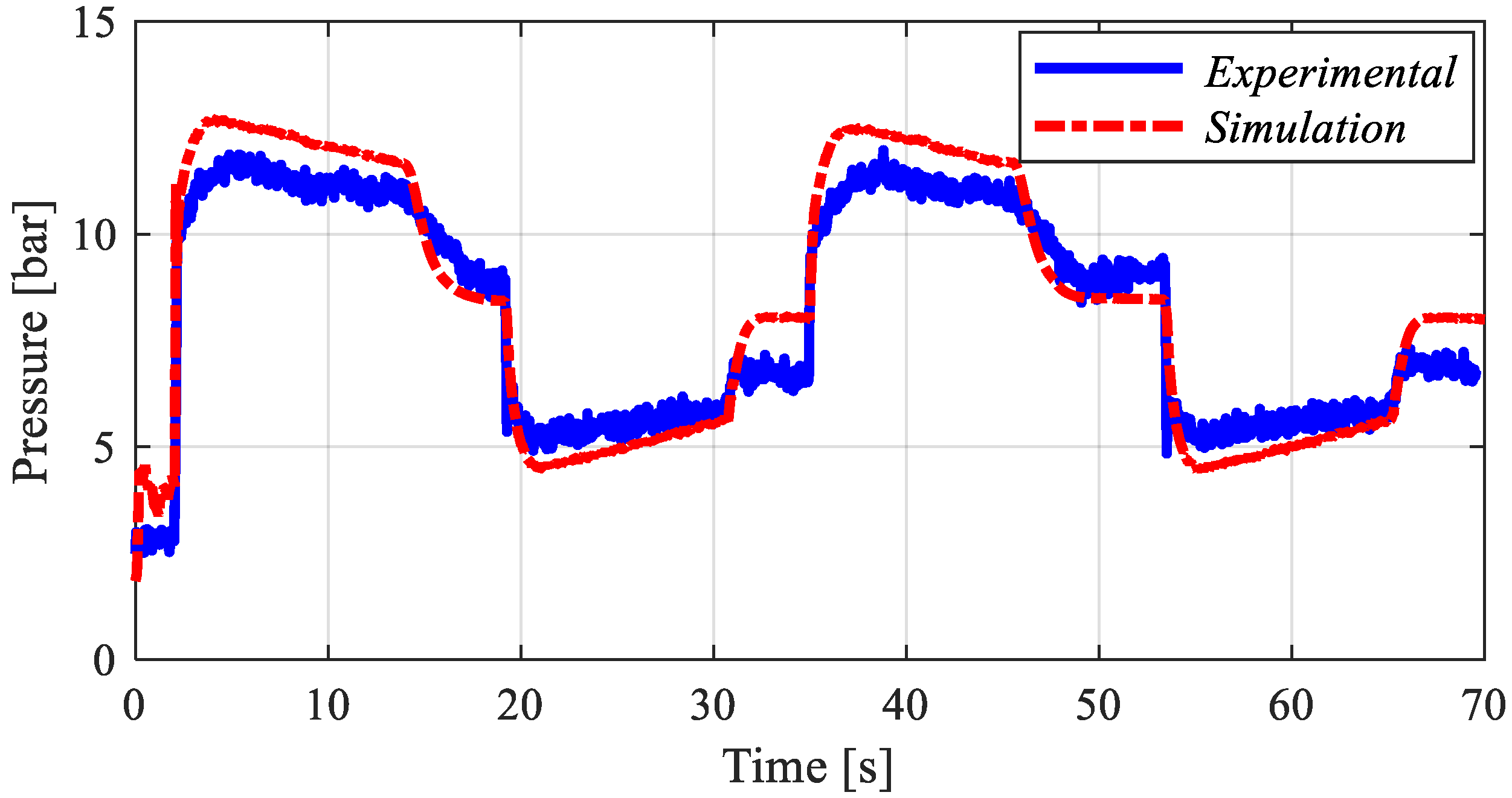
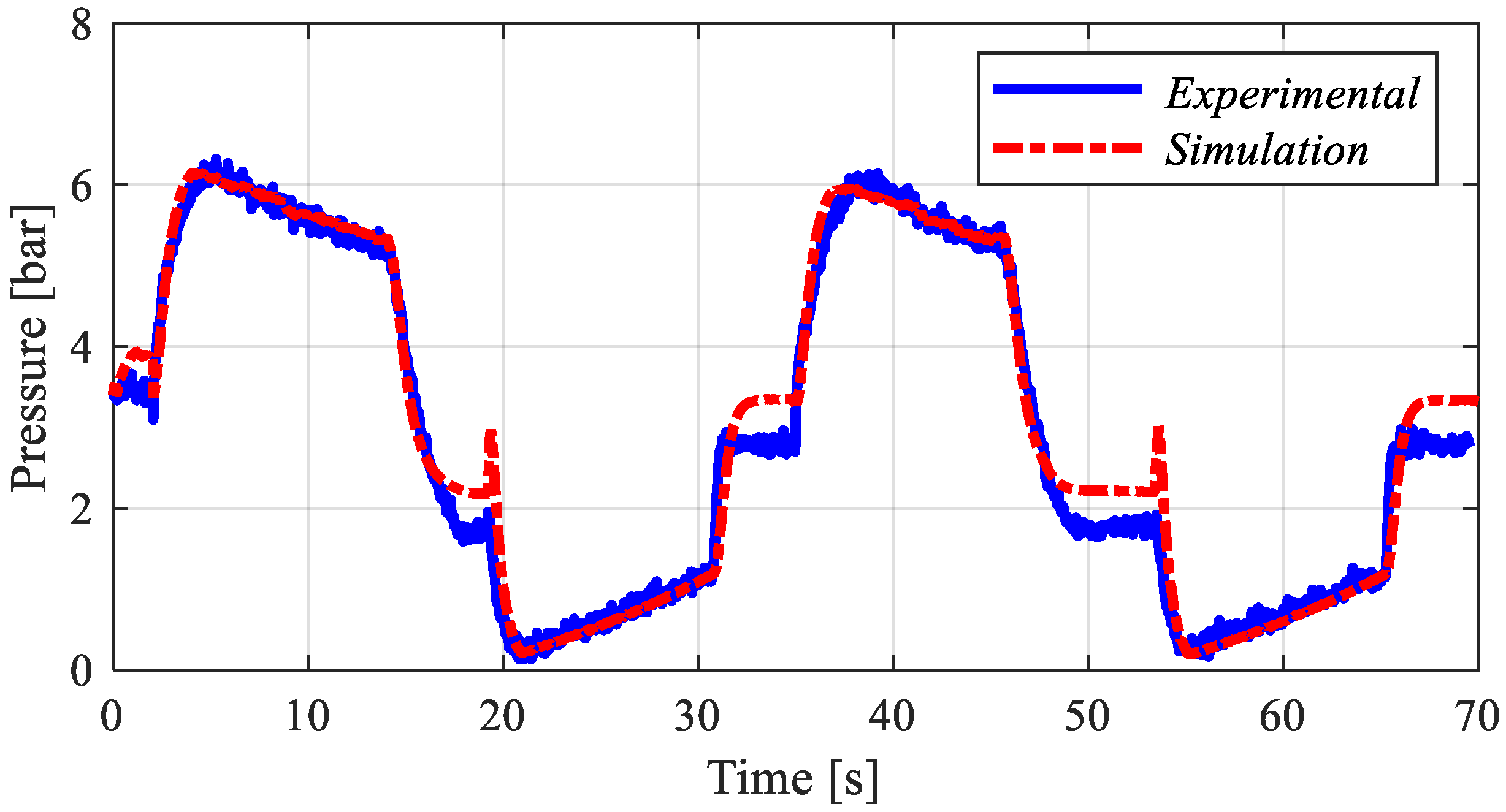
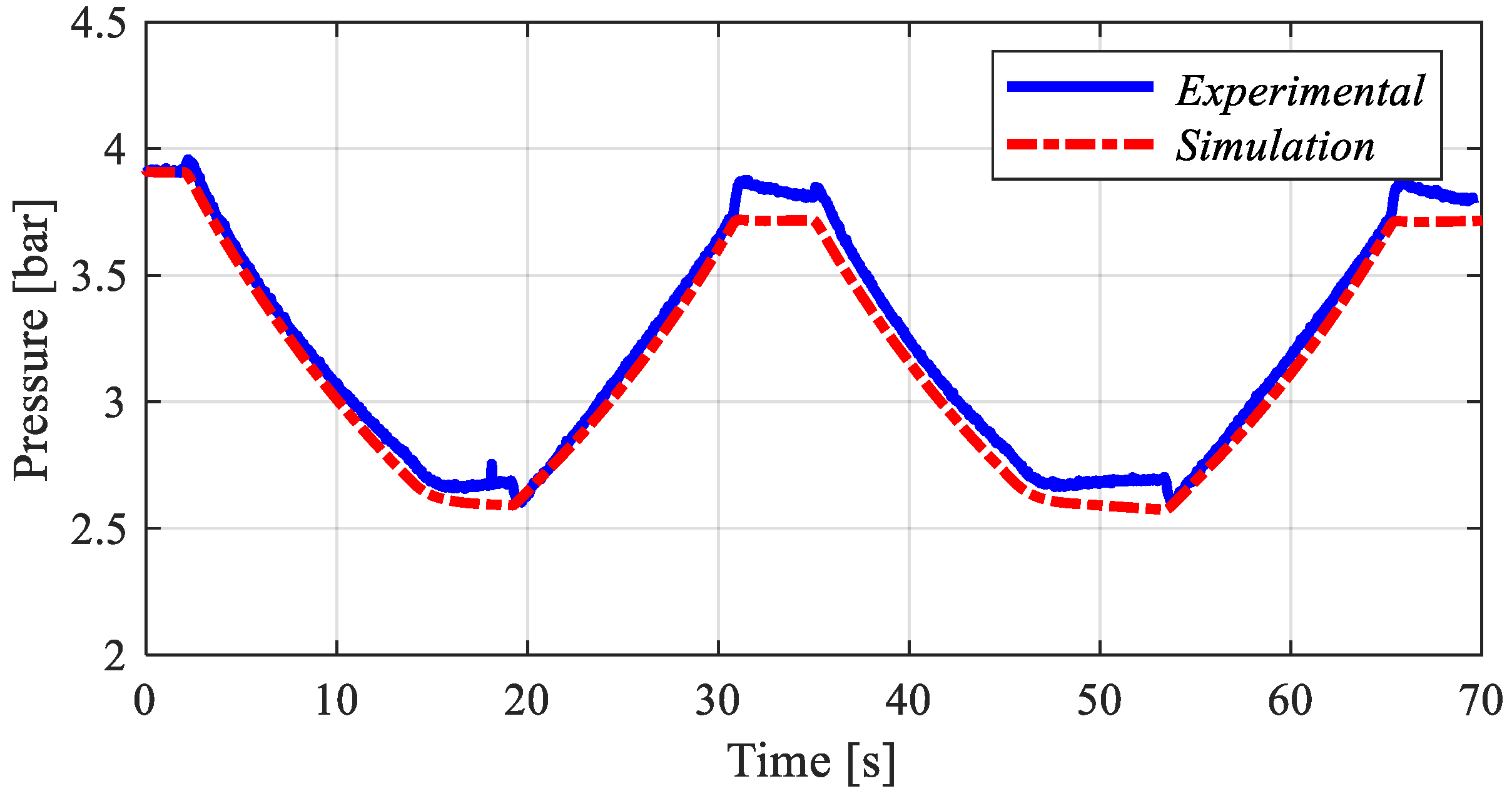
This section describes the mathematical model utilized to represent the hydraulic components and the crane load in MATLAB/Simulink. The model considers an ideal source of speed driving two pump/motors. The main parameters utilized in the model are presented later in this section based on experimental validation.
The pump/motor effective volumetric flow rate is expressed by:
where
is the volumetric displacement,
is the angular speed, and
the sum of internal and external leakages.
The leakages depend on the differential pressure over the pump/motor and its angular speed. They are determined by:
where
and
are constant values calculated for each pump/motor based on the manufacturer catalogue information and experimental data.
Three control volumes are considered in the system: The two chambers of the cylinder and the low-pressure volume in the accumulator line. The effective bulk modulus,
, represents the total compressibility of the system considering oil, air trapped inside the circuit, and hoses. It is calculated by:
where
is the bulk modulus of the hoses,
is the bulk modulus of the hydraulic fluid,
is the volume of air trapped in the system,
the total volume, and
the bulk modulus of the gas, which is a variable value and considered the instantaneous pressure in the system.
The pressure dynamics of the chambers was modeled utilizing the continuity equation for a control volume, that is:
where
is the pressure derivative inside the closed volume,
the initial volume of the chamber, and
the volume variation in time.
The friction force of the cylinder was based on the LuGre model given by:
where
is the stiffness of the elastic bristles,
is the damping coefficient, and
is the viscous friction coefficient. The
and
represent the average deflection and deflection rate of the bristles, respectively.
is a positive function and depends, for instance, on material properties, lubrication, and temperature.
is the Coulomb friction force,
is the static friction force, and
is the Stribeck velocity. The friction parameters utilized in the simulation were obtained experimentally previously by [
12].
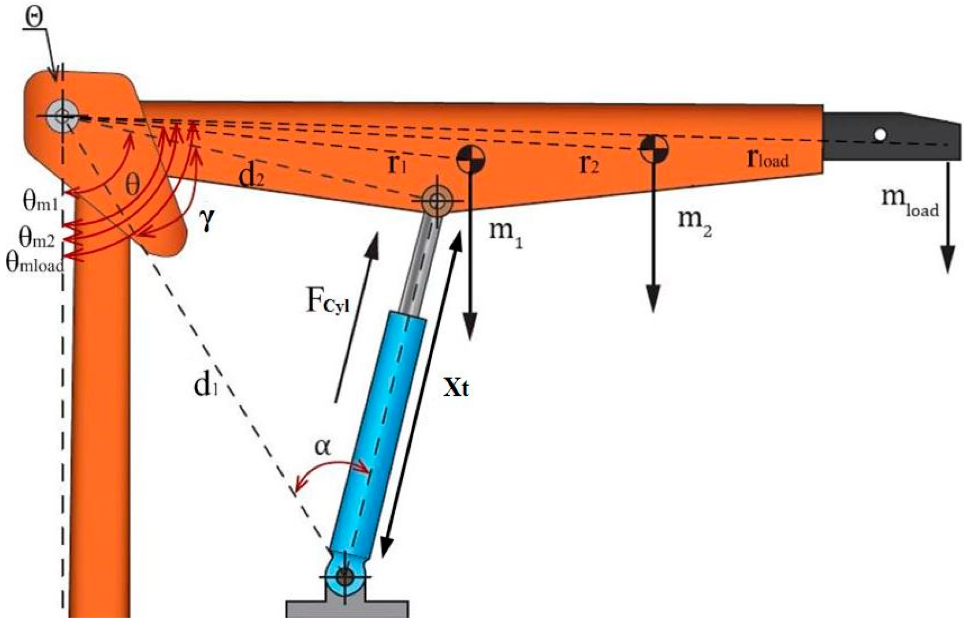
The load force applied in the system is represented by the free body diagram of the crane in
Figure 3.
The load force acts at the extremity of the crane structure generating a torque around the joint Θ, determined by:
where
is the angular acceleration which can be rewritten decomposing the forces acting in
Figure 3 as:
where
and
are the masses of the segments the crane is composed of,
and
are the distance between the centre of mass of each segment and the joint,
and
are the angle between the center of mass and the reference perpendicular axis, and g is the gravitational constant. Payload is attached to the crane with a chain. For simplification, the load is considered at the point the chain is attached to the movable part, such that
considers the mass of the load, chain, and the hook.
is the net hydraulic force,
is the angle between the cylinder and the joint, and
the distance between the cylinder base and the joint.
The angles
shown in
Figure 3 can all be determined in the function of
by their initial values measured when the cylinder is fully retracted plus the variation of
:
and angle
is found using the sine rule given by:
where
is the distance of the upper fastening point of the cylinder and the joint.
is the body length of the cylinder when fully retracted plus the stroke displacement. To obtain
the cosine rule is utilized, resulting in:
Deriving Equation (15) in function of time
, the velocity of the cylinder can be expressed by:
Check valves for anti-cavitation purposes were modeled as an orifice allowing volumetric flow from the reservoir to the cylinder chambers when the pressure difference over the valves is 2.5 bar. The pressure relief valves were also modeled as an orifice that allows volumetric flow when the chamber pressure reaches the cracking pressure. The influence of the valve dynamic was not investigated.
The following sections present the experiment results and the model validation, as well as the energy analysis.
5. Results and Discussion
5.1. Energy Analysis
Using the validated model presented above, the system is now analyzed in terms of consumed and delivered power, as well as energy efficiency. The influence of ratio between pump/motor displacements and cylinder areas is also discussed.
The torque
required by both pump/motors is calculated by:
and the power at the electric motor shaft is given by:
where mechanical efficiency,
, is based on the catalogue data.
The useful cylinder mechanical power is calculated by:
where
is the net force exerted by the cylinder and
is the position.
The electric motor and cylinder powers along the cycle are presented in
Figure 9. The time intervals where the power values are positive represent the lifting motion and the negative values represent the lowering motion. In order to estimate the energy and efficiency all over the cycle, the input and output powers are defined according to the flow power direction. In other words, when the actuator is advancing, the input power is considered on the electric motor shaft and the output power on the cylinder piston. In the opposite motion direction, the input power is that resulting from the load potential energy and the output power is on the motor shaft.
The input and output energies are determined by integrating the powers in each motion and sum given by:
and
where the time instants are shown in
Figure 9.
The energy analysis can be done in two different approaches. First, considering that the energy available in the electric motor shaft when lowering the crane can be sent back to the grid (or battery pack), recovering energy. In this case, the overall efficiency is determined considering all parts involved in Equation (21).
The other approach is not considering the capacity of energy recovery, working similarly to the conventional meter-out flow control system and wasting the stored potential energy. The energy in the electric motor shaft is just dissipated and, consequently, there is not an opposite torque. In this case, the torque () dependent terms in Equation (21) are neglected.
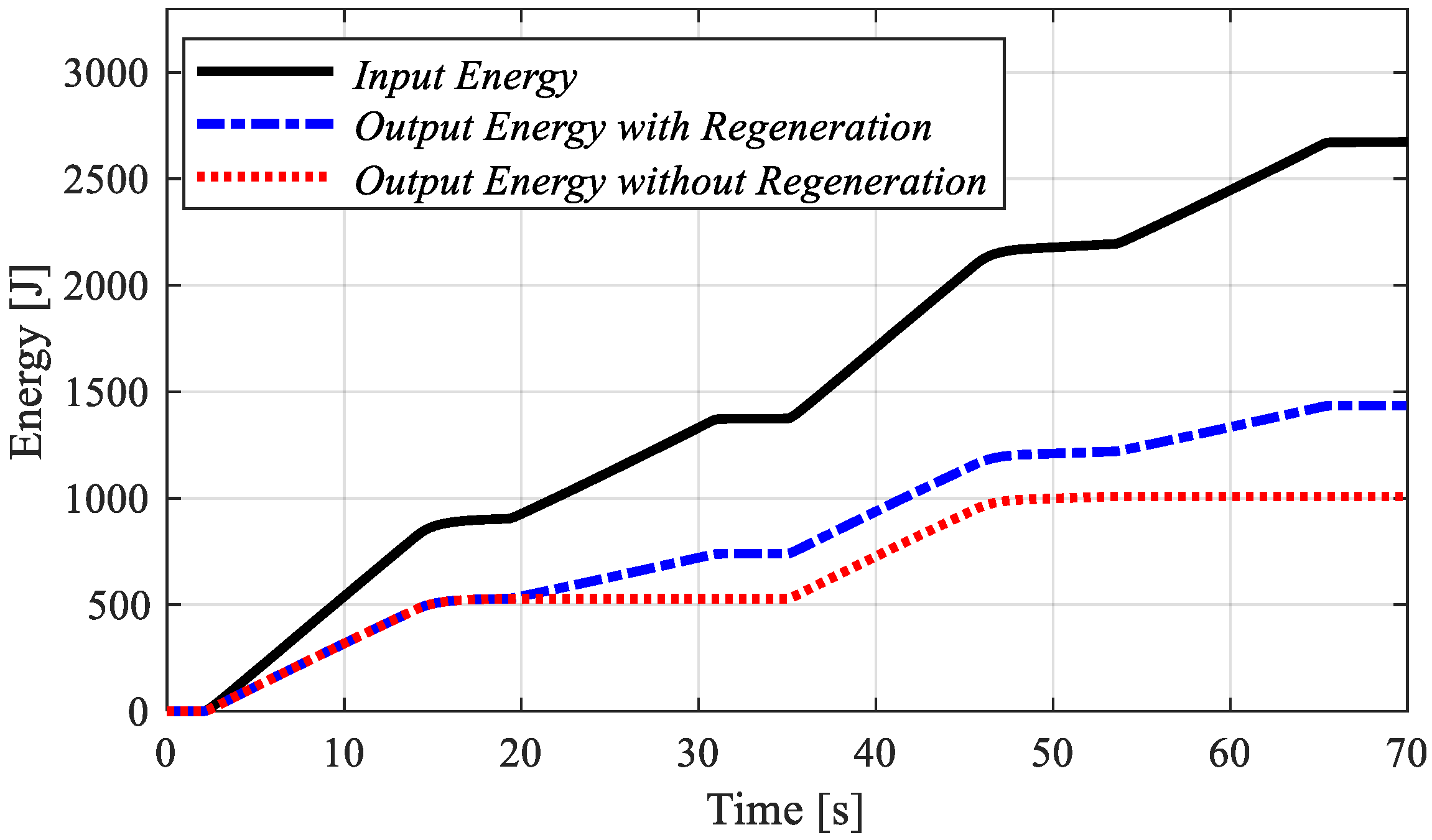
Energy values with and without energy recovery can be seen in
Figure 10.
In
Figure 10, the black line corresponds to the input energy involved to perform the whole motion present, the red line consists of the total mechanical energy from the cylinder motion, and the blue presents the amount of mechanical energy of the cylinder plus the amount for energy that is captured by the electric motor during the cylinder retraction.
The total efficiency when the system is able to recover energy resulted in approximately 54%, while the system without energy recovery was around 38%. These values are only taken into account the hydraulic component losses, not considering the energy conversion at the electric motor.
5.2. Influence of the Volumetric Displcacemnt Ratios
It is important to notice that the leakages of both pump/motors have a significant influence on the system performance, especially when operating in higher rotational frequencies as shown in Equation (2). When the cylinder is advancing, the flow suction of the pump/motor on the rod side chamber (B-Side) is lower than the resulting from the cylinder displacement creating a counter pressure in the actuator chamber B (see
Figure 7). The faster the cylinder moves, the higher the pressure is, limiting the crane operation range. In this system condition, when rotational frequencies are higher than 550 rpm, the pressure relief valve opens (30 bar). As the pressure in chamber B increases, the pressure in chamber An increases as well, resulting in a higher net torque in the pump/motor shaft.
To improve the energy efficiency, two possible approaches are proposed. The first one is utilizing the pressure relief valve in order to avoid the counter pressure caused by the unbalance volumetric displacements of pump/motors compared to the area ratio of the actuator. A low cracking pressure of the valve can significantly improve the efficiency and allow operation with high speed. The second one is to match the effective volumetric flow of the pump/motors with the effective inflow and outflow of the actuator. A thorough analysis needs to be carried out regarding the real volumetric displacement and the real leakage curve, in a function of differential pressure and rotational frequency in each pump/motor. This would provide the range conditions the system could operate to maximize its efficiency. Considering this, the second approach is desirable, once it can overcome the relief valve losses.
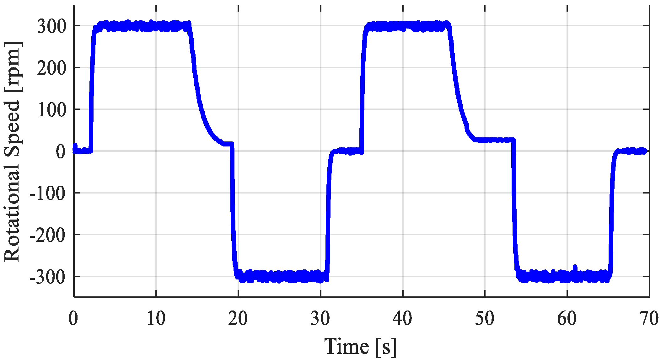
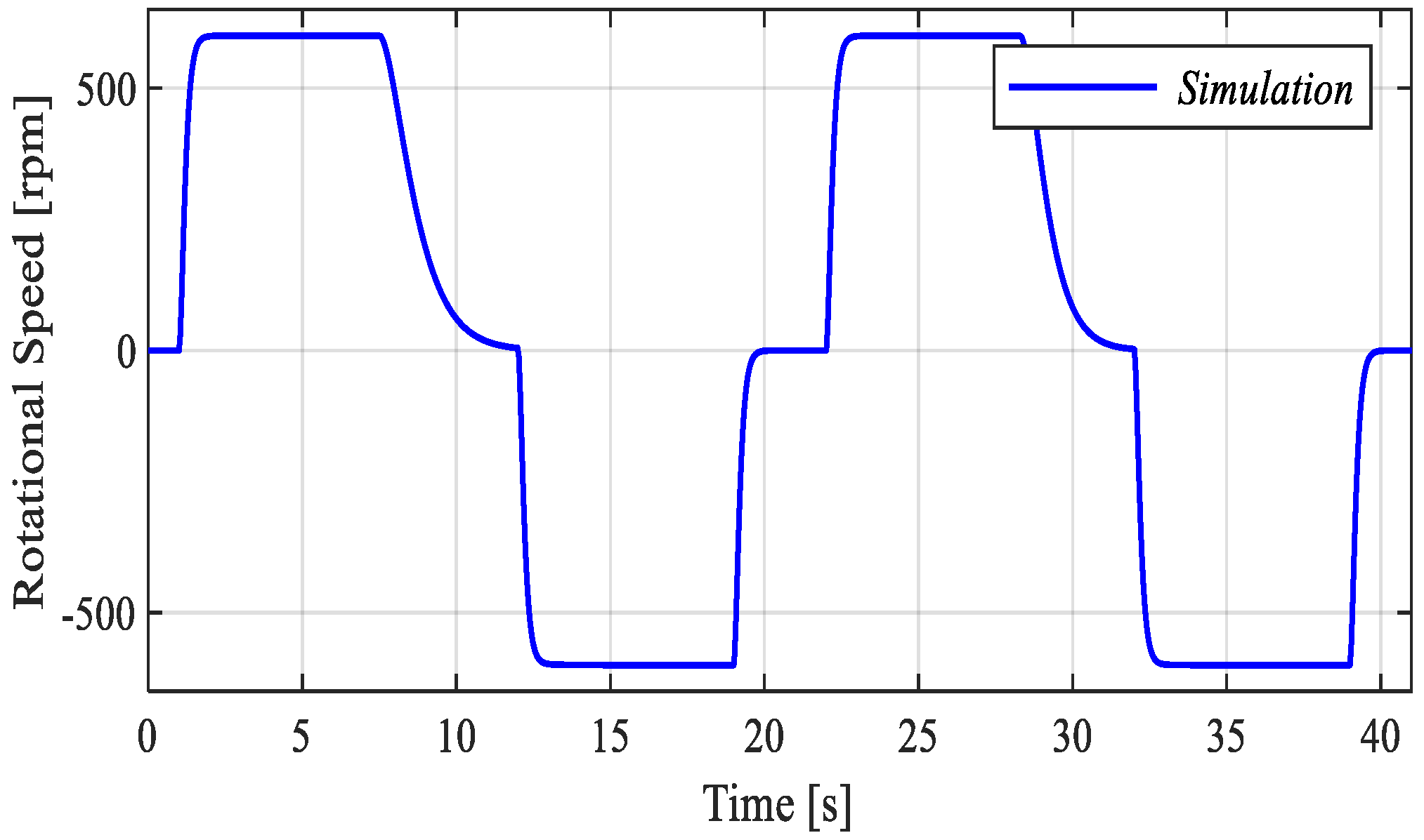
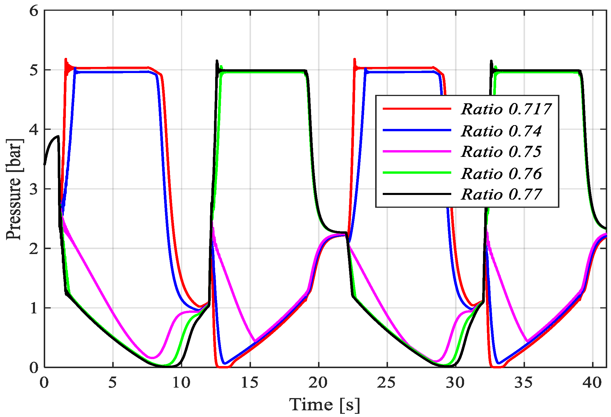
To investigate the influence and sensitivity of the correct ratio between areas and displacements, different dynamic behaviors were analyzed by adjusting the B-Side pump/motor displacement. The analyzed displacement ratios vary from the experimental setup value (0.717) to the assumed optimal condition based on the cylinder area ratio (0.75). The simulation conditions considered a load mass of 200 kg and a maximum rotational frequency of 600 rpm. The input rotational speed and the cylinder position are shown in
Figure 11 and
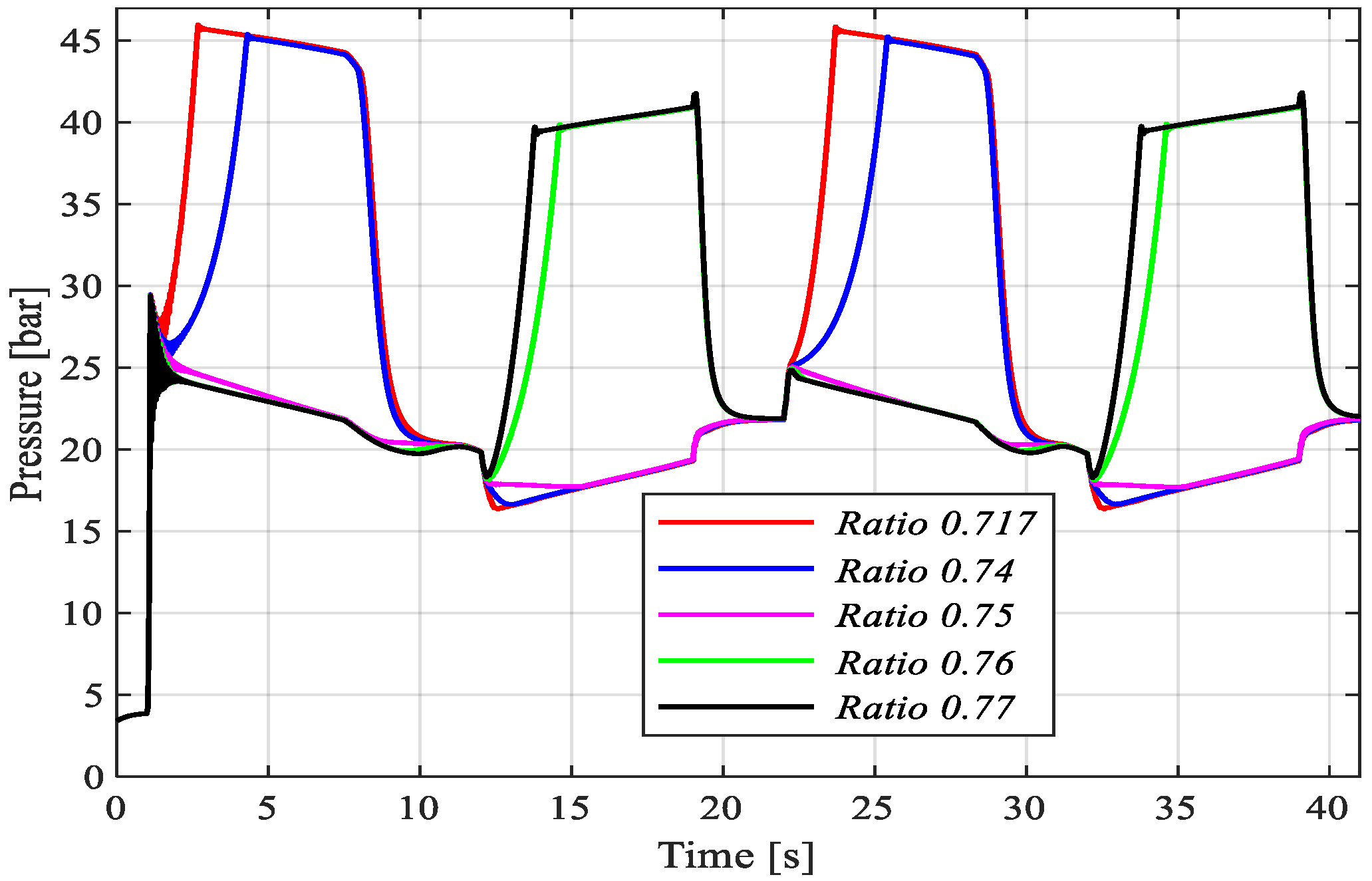
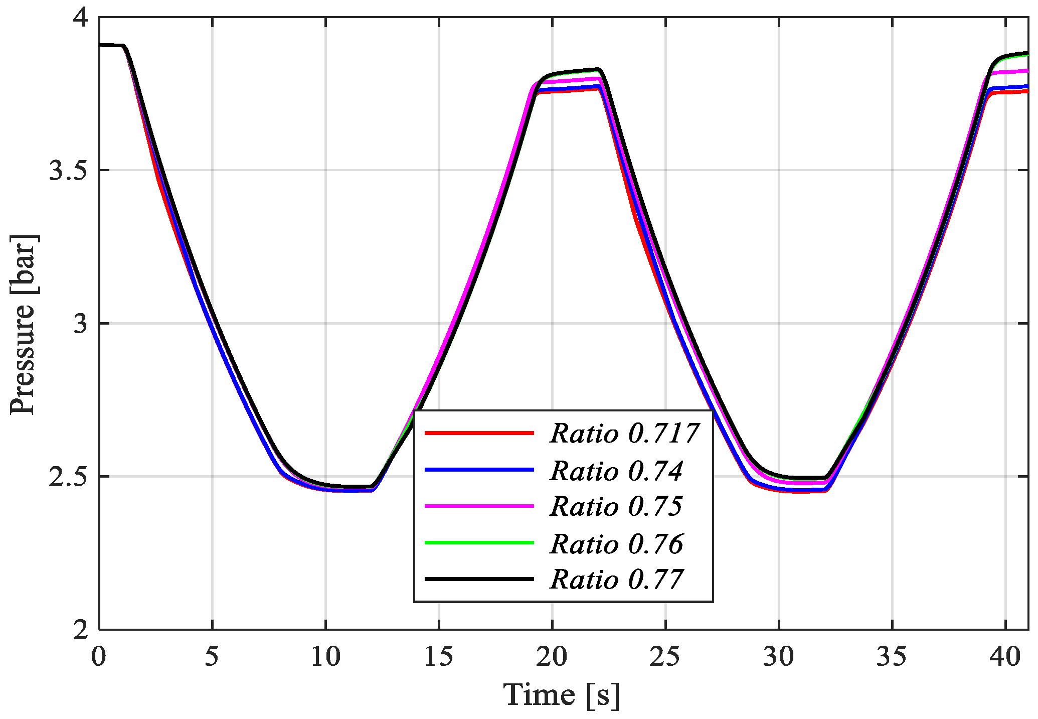
Figure 12, respectively. The pressure levels in the cylinder chamber are illustrated in
Figure 13 and
Figure 14 for four displacement ratios between the pump/motors.
Figure 15 presents the corresponding accumulator line pressure.
As shown in
Figure 13, the pressures have a sudden increase during the lifting motion when the displacement ratio is not near the optimal value. The pressures in
Figure 14 are limited by the pressure relief valves on the rod side and a lower cracking pressure could lead to higher efficiencies due to smaller counter-pressure generated. This high sensitivity on the ratio unbalance (0.01) supports the idea that each operation condition has an optimal condition of ratios due to the pump leakages varying with rotational frequency and the pressure over the pumps. In order to obtain a better condition as close as possible, the 0.75 ratio should be used for both pumps and cylinder areas. Utilizing fixed-displacement pump/motors, with volumetric flow depending on the pressure and rotational speed, it is impossible to achieve its maximum potential without auxiliary valves. Another fact to be considered in this system is the load force direction, in this case a static compression load is reducing the complexity to work with this system configuration so the valves can passively work. In other words, the absence of change of load direction implies no need of piloted valves.
In order to investigate the influence of the cracking pressure of the relief valve, simulation with 5 bar was carried out under the same conditions above.
Figure 16 and
Figure 17 show the pressure behavior in the chambers. The accumulator line presents similar curves as in
Figure 15.
Table 3 summarizes the overall efficiencies achieved for each displacement ratio and different system conditions. For each case performed, considering and not considering regeneration was evaluated. Ratios above 0.75 were also included to support the idea that ratios near 0.75 are in fact optimal values and higher ratios would not increase the efficiency due to the losses occurring in the pressure relief valves.
5.3. Comparison with an Electro Hydraulic System
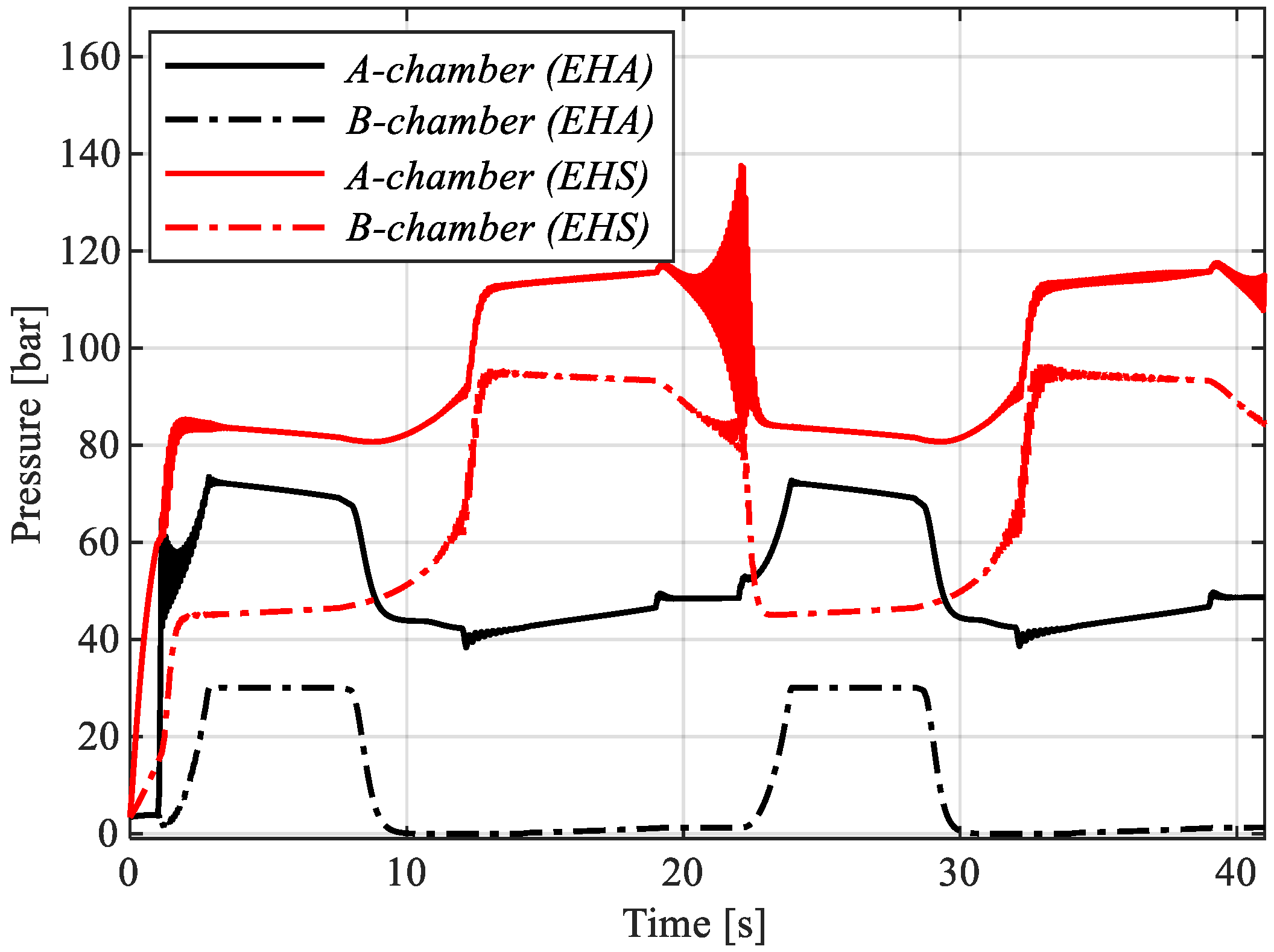
In order to compare the energy efficiency gained from an electro-hydrostatic actuator (EHA) with an electro hydraulic system (EHS), utilizing a cylinder controlled by a directional proportional valve with constant pressure source, both systems under the same load condition and actuator motion were analyzed. A load mass of 500 kg was assumed in order to evaluate the system performance in work conditions close to nominal operating conditions. The cylinder position (see
Figure 12) was used as the reference input signal, this way it was able to evaluate the different concepts.
In the EHS model, the cylinder pressure was limited to 130 bar during an operation condition, so it was considered with a constant supply pressure of 160 bar and the efficiency of the pressure source of 75% for a variable-displacement pump (piston pump). This is the mean value for a piston pump operating between 30% and 100% of volumetric displacement at 160 bar and 1775 rev/min [
14]. The directional proportional valve model was based on [
15], an asymmetrical proportional valve with 2:1 orifice ratio.
Figure 18 presents the pressure levels in the chambers for both actuation systems.
Table 4 presents the approximate values obtained for the condition simulated using both systems.
The results presented in
Table 4 showed the amount of energy and power that can be saved implementing a power-on-demand actuation system. Even adopting conservative values for pressure source and prime mover efficiency, in terms of maximum input power, the EHA required only 46% of the power required by EHS, i.e., consumed. The energy consumed along the motion performed was 41% less, consequently, the overall efficiency resulted in a significant improvement.
6. Conclusions
A nonlinear dynamic model of the electro-hydrostatic actuator, including pressure and flow-dependent leakages at the pump/motors and cylinder LuGre friction, was developed and validated experimentally. Based on the simulation and experimental results, the proposed system architecture resulted in an efficiency of 38% when electrical energy regeneration is not considered, and up to 54% with energy regeneration when operating with a load mass of 40 kg.
The impact of the volumetric displacement ratio of the pump/motors is analyzed using the validated model. Since no directional valves are included in the system to balance the inflow and outflow from the differential cylinder, it should be done by the pump/motors. The results revealed that a change from ratio 0.74 to 0.75 (ideally value) on the volumetric displacement leads to a difference of 10% on the energy efficiency for a specific working cycle, load mass, and maximum rotational frequency. As a general conclusion, the design target is to select the pump/motor and cylinder with displacement ratio and area ratio, respectively, as close as possible.
Since achieving the perfect match between pump/motor and cylinder is a hard task, one option is reducing the cracking pressure of the relief valve on the rod side. Consequently, the cylinder counter-pressure is reduced, allowing the system to operate in an efficiency range near the optimal condition.
The energy performance of the proposed EHA was also compared with an EHS where the throttle losses and leakage through the proportional valve are present. The consumed energy was 46% lower to move a load of 500 kg at the same trajectory.
Therefore, besides an expected unbalance between pump/motor volumetric displacements and cylinder areas, an EHA with two pump/motors driving an asymmetrical cylinder can achieve a substantial gain considering energy consumption if compared to the conventional valve-controlled system.
