Article

A Rotational Order Vibration Reduction Method Using a Regular Non-Circular Pulley

School of Mechanical and Electrical Engineering, Guangzhou University, Guangzhou 510006, China
*
Author to whom correspondence should be addressed.
Actuators 2025, 14(8), 371; https://doi.org/10.3390/act14080371
Submission received: 6 June 2025 / Revised: 15 July 2025 / Accepted: 18 July 2025 / Published: 25 July 2025

Abstract

For transmission systems with regular order excitation, the order vibration will be conducted to each component of the system and affect the stability and service life of the system. A method with a regular non-circular active pulley is proposed in this paper, which is used to counteract the regular order excitation and the regular load excitation. A toothed belt drive system with second-order excitation is taken as an example. According to the existing analytical model of the tooth belt drive system, the modeling process and analytical solution algorithm of the system are derived. Based on the coordinate transformation, the algorithms for any position of an elliptical pulley and the common tangent of the circular pulley are given. And the algorithm for the arc length of the elliptical pulley at any arc degree is proposed. The influence of the phase and eccentricity in the elliptical pulley on the dynamic performance of the system is analyzed. Then the experimental verification is carried out. This shows that this system can generate excitation opposite to the main order rotational vibration of the driving pulley and opposite to the load of the driven pulley. Under the combined effect of other load pulleys in the system, there will be an amplification phenomenon in its vibration response. Considering the decrease in the belt span tension and the decline in the performance of energy-absorbing components after long operation, the presented method can better maintain the stability of system performance. This method can provide new ideas for the vibration reduction optimization process of systems with first-order wave excitation.

1. Introduction

1.1. Motivations

In a system using rotational motion as excitation, there exist situations involving regular order excitation and loads [1,2,3,4]. As an example of a belt drive system, the driving pulley drives the other pulleys via a belt to transmit power. Meanwhile, if the driving pulley has rotational speed fluctuations, the driven pulley will also experience rotational speed fluctuations of the same frequency [5]. These regularly fluctuating excitations and loads will be transmitted to the system components, generating additional vibration [5], noise [6], and even fatigue damage [7].
Existing solutions are to add energy-absorbing or appropriate vibration isolation components to the system to counteract vibration and absorb additional energy [8,9,10]. However, for rotary excitation systems with a wide frequency range, the requirements for the vibration isolation components are very strict [11,12,13]. And it is often difficult to achieve a good vibration-absorption effect [6,14]. Furthermore, in some cases, it is impossible to add additional vibration damping units [15].
For this problem, a system scheme containing a non-circular pulley is proposed in this paper, designing regular contours to generate excitations and loads that can counteract the regular order in the system. The engine timing belt drive system with second-order excitation is taken as an example. A vibration reduction design method with an elliptical driving pulley is proposed. The dynamic model and analytical solution algorithm of the system are established and verified. And the vibration reduction control and parameter design process of the system are also analyzed.

1.2. Literature Reviews and Objectives

In terms of the response optimization methods of belt drive systems, researchers have conducted in-depth research. In [16], the authors established a modified method for the natural frequency of belt pulley systems. By differentiating the eigenvalue equation, the explicit expressions of the natural frequency and the eigenvectors of the structural parameters were obtained. In [17], the authors established a coupled vibration model and analyzed the sensitivity of tensioner parameters to system tension fluctuations and band vibration. In [18,19], the authors proposed an adaptive particle swarm optimization genetic algorithm to improve the performance of the automatic tensioner, which is the vibration-absorbing unit. And he proposed a mutation particle swarm optimization algorithm to optimize the important structural parameters for vibration control.
In order to counteract the order vibration, the authors in [20] were among the first to propose a non-circular pulley for use in a multi-pulley drive system. By changing the contour of the rotating pulley, a corrective torque is generated on a belt drive system, which was opposite in phase and similar in frequency and amplitude to the crankshaft excitation and the load torque fluctuation. Based on the rigid–flexible coupling principle, the authors in [21] used the software Simdrive to perform dynamic calculations on the timing system with a non-circular pulley. In [22,23], the authors proposed a toothed belt drive system dynamic model with an elliptical pulley. The second-order torque generated by the elliptical pulley and the fluctuation of the belt tightness are utilized to counteract the periodic load of the system, reducing the pulley rotational vibration and the belt span vibration. The AVL-Excite software was applied to analyze the principle of the timing transmission system with an eccentric structure by two researchers [14,15,16,17,18,19,20,21,22,23,24,25]. The dynamic responses of non-circular pulleys with different shapes and phases were calculated and compared. In [26], the authors utilized the periodic shape and position errors during the rotation of non-circular pulleys to achieve pitch line trajectory control and proposed a mechanism design and analysis method for periodically changing transmission ratios between the driving pulley and driven pulleys.
In previous studies [16,17,18,19,20,21,22,23,24,25,26], the traditional drive system optimization is to optimize the tensioner parameters to achieve better system vibration responses. The use of an on-circular pulley can counteract and reduce the excitation and load. But the existing methods focus on the drive system matching algorithm, and the solution of the geometric relationship of non-circular contours takes a long time, involving a huge amount of calculation. Thus, the aim of the paper is to propose an analytical method for the position and length of the common tangent between an elliptical pulley and a circular pulley at any phase and eccentricity, as well as to find the law of the elliptical pulley for the vibration response of the system in different application scenarios.
The organization is given as follows: Firstly, the modeling process for the belt drive system with an elliptical pulley is established, and the analytical method for the position and length of the common tangent between an elliptical pulley and a circular pulley is proposed. In Section 3, the influence of elliptical pulley parameters on the dynamic performance of the system is analyzed. In Section 4, the test method and verification of the established model and method are given. Conclusions are given in the conclusion.

2. Modeling and Solution of the Timing Belt System with a Non-Circular Pulley

As we know, in an engine timing belt drive system, the crankshaft pulley is a typical driving pulley with order excitation velocity. Thus in this section, taking the five pulley timing belt drive systems in four-cylinder gasoline engines as examples, the crankshaft pulley is improved from a circular pulley to an elliptical structure. The modeling method and solution method of the system with an elliptical pulley are described.

2.1. Modeling of Timing Drive System with Elliptical Pulley

2.1.1. Modeling of Belt Drive System with Elliptical Pulley

As shown in Figure 1, the timing belt drive system uses excitation from the crankshaft pulley in a clockwise direction with a periodic rotational vibration. The system consists of a crankshaft (CRK) elliptical pulley, an idler (IDL) on the tight side, two camshafts pulleys (CAM1 and CAM2), and a tensioner (TEN) on the slack side. The coordinate O-XY is established with an origin point in the center of the crankshaft pulley, and all the pulleys are described according to the coordinate. L i and K i are the length and the stiffness of the ith belt span, respectively. θ i and θ t denote the angular displacements of the ith pulley and the tensioning arm, respectively. ψ 1 and ψ 2 are the angles from the fourth and fifth belt spans to the negative X-axis in the anticlockwise direction, respectively.
According to the reference [27], the system’s dynamic model are described as follows:
I i θ ¨ i + C i θ ˙ i + M i = R i T i 1 T i , i = 2 , 3 , 4 , 5 I 5 + I t θ ¨ t + C e q θ ˙ t + M t = T 4 L t s i n β 1 T 5 L t s i n β 2
where C i and M i are the damping and transmitted loads of the ith pulley, respectively; C e q and M t are the equivalent viscous damping and the hysteresis torque of the tensioner, respectively; I i and I t describe the inertial moments of the ith pulley and the tensioning arm rotating around its pivot, respectively; T i denotes the belt tension of the ith belt span; and M B is the moment caused by the belt tensions of the two spans adjacent to the tensioner pulley, where L t is the arm length of the tensioner and β 1 and β 2 are the inclination angles between the tensioning arm and the two adjacent belt spans, respectively, as expressed in Equation (2).
β 1 = Ψ 1 θ t π , β 2 = π Ψ 2 + θ t
The belt tension T i is calculated by Hook’s law, as shown below.
T i = T 0 + K i Δ i
K i = E b A / L i
where T 0 is the pretension on the belt; K i , L i , and Δ t indicate the stiffness, length, and length variation in the belt span B i , respectively; and E b and A describe the elastic modulus and the cross area of the belt, respectively.
According to references [1,27], the belt creeping on the contact arc of the belt and the belt length variation in the meshed teeth area are tiny and can thus be ignored. Therefore, the description of the belt span elongation in the system with an elliptical crankshaft pulley is given as follows:
Δ i = 0 t R 1 θ ˙ 1 d σ θ 2 R 2
Δ 5 = θ 5 R 5 0 t R 1 θ ˙ 1 d σ + Δ L 5
where R i is the radius of the ith pulley; Δ L i denotes the belt length variation generated by the tensioning arm motion; 0 t R 1 θ ˙ 1 d σ is the rotating arc length of the elliptical pulley during the running time; and σ is an integral variable.
Based on the system layout in Figure 1, the belt length variation ( Δ L i ) is calculated as follows:
Δ L i = L i θ t θ t 0 s i n β 1 , i = 4 L t θ t θ t 0 s i n β 2 , i = 5

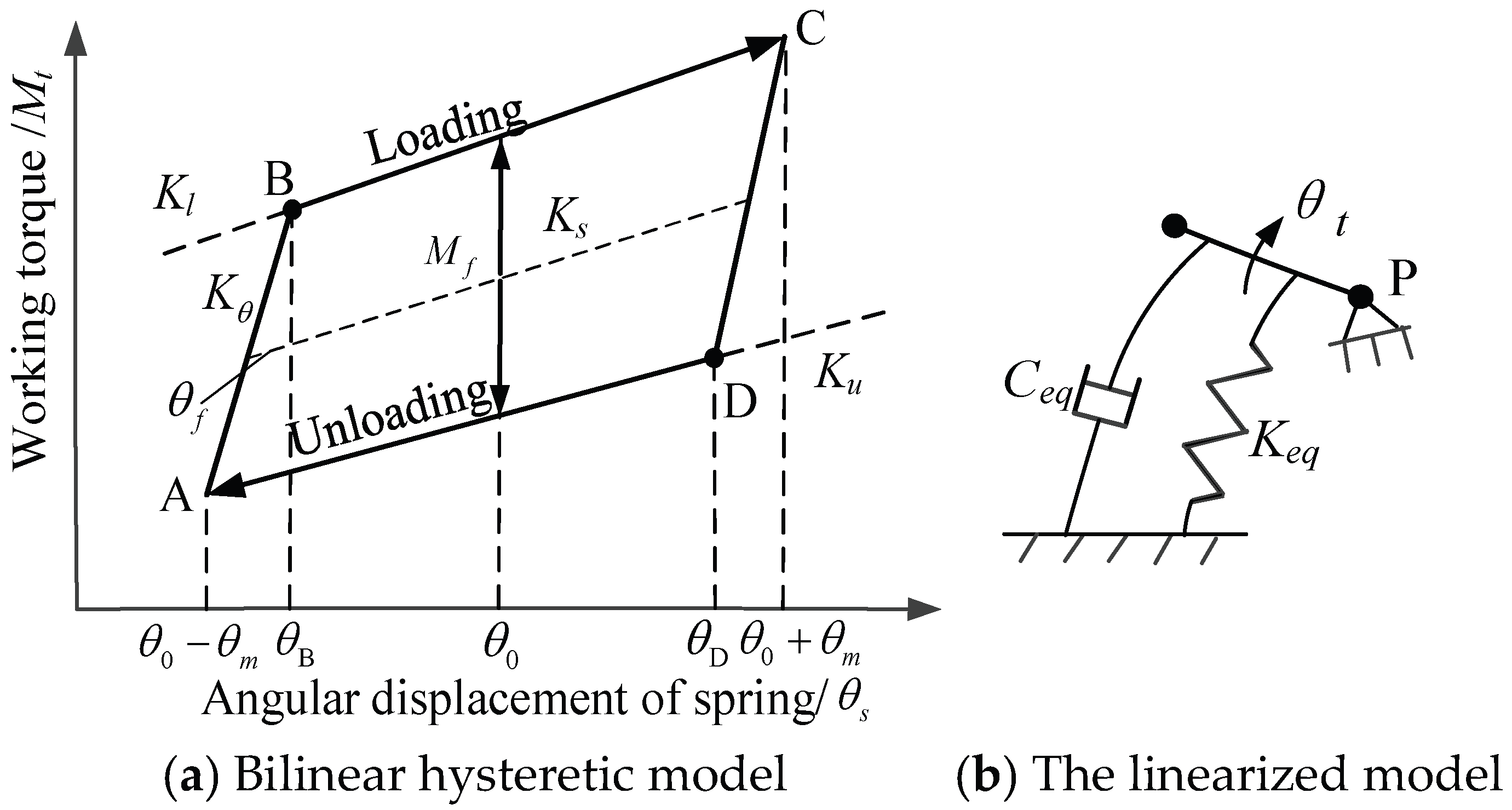
2.1.2. Hysteretic Model of the Tensioner

The tensioner is an important vibration-absorbing component of the system. According to reference [27], the reaction torque of the tensioner versus its rotational angle behaves in a state of hysteresis. Here a bilinear model that can ensure a certain level of accuracy is adopted to describe the friction type tensioner, as shown in Figure 2.
In Figure 2a, K s and K θ represent the spring stiffness and the lag stiffness, respectively. K l and K u represent the loading stiffness and the unloading stiffness, respectively. θ f and θ m are the lag angle and rotational amplitude of the tensioning arm in the hysteretic stage, respectively. C e q and K e q are the equivalent damping and the equivalent linear stiffness of tensioner. M f is the friction torque during the loading and unloading process.
Assuming that the belt drive system is excited by a sinusoidal excitation, the approximate solution of the system responses of the tensioning arm can be expressed as
θ t = θ m s i n ω t t + φ t
where ω t and φ t denote the vibration frequency and the phase of the tensioning arm and t is the time.
According to reference [27], the torque of the tensioner is described as
M θ t   , θ ˙ t = C e q θ ˙ t + K e q θ t
where C e q θ ˙ t and K e q θ t are the equivalent damping torque and the equivalent hysteresis torque, respectively.
The equivalent damping and the equivalent linear stiffness of the tensioner are described as
C e q = 4 M f π ω θ m 1 θ f θ m
K e q = K θ π θ * s i n θ * c o s θ *
where θ * denotes the cyclic lag angle, as given in Equation (12).
θ * = a r c   c o s ( 1 2 θ f θ m )
Thus the torque of the tensioner in Equation (1) is rewritten as
M t = K e q θ t θ t 0 + Q t
Q t = K s θ t 0 α t
where θ t 0 and Q t are the angular displacement of the tensioning arm and the preloading torque in the initial equilibrium position and α t is the zero-torque angular displacement of the tensioner.

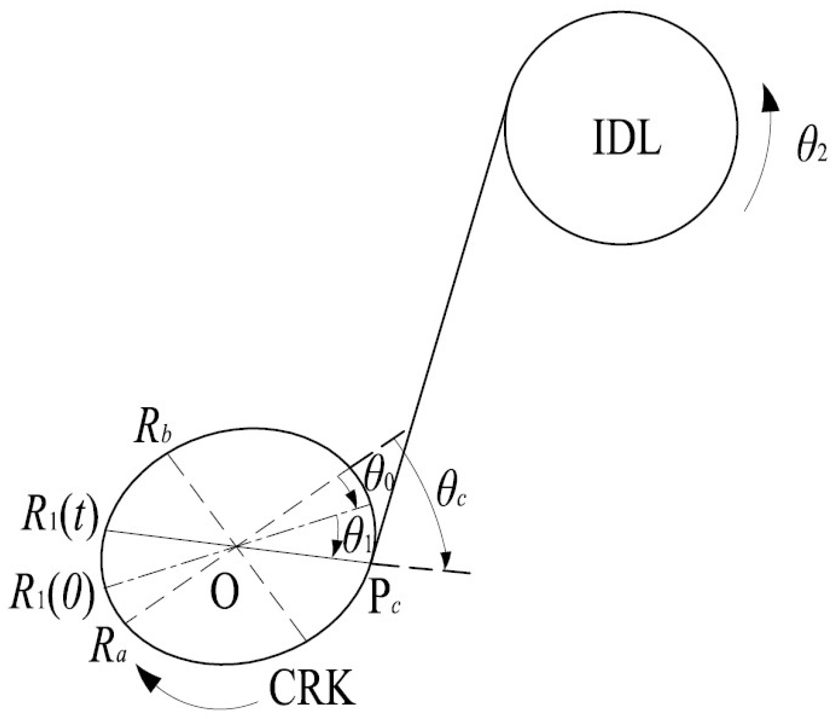
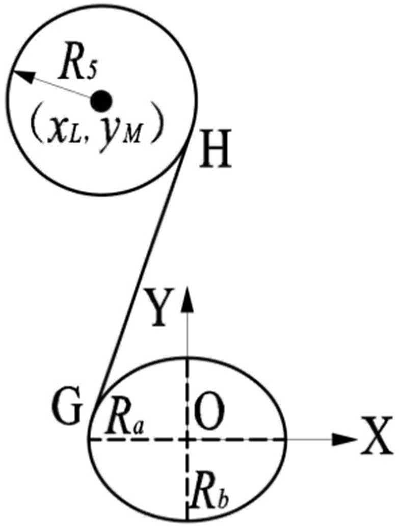
2.2. Method for Calculating Tangent Point and Tangent Length of Rotating Elliptical Pulley

2.2.1. The Definition and Parameters of Elliptical Pulley

The schematic diagram of the position and angle of the elliptical crankshaft pulley with time t is shown in Figure 3.
In Figure 3, the major axis radius and minor axis radius of the elliptical crankshaft pulley (CRK) are denoted as R a and R b , respectively. If the crankshaft pulley rotates through an angle θ 1 at time t, the radius at the tight side changes from R 1 (0) to R 1 (t). P c represents the tangent point on the tight-side belt span at time t, and θ 0 and θ c denote the angles between the radial axis at the tangent point and the major axis at the initial moment and time t, respectively.
If the time is t, the radius of the crankshaft at the tight side R 1 (t) becomes
R 1 t = R a 2 c o s 2 θ c + R b 2 s i n 2 θ c
θ c = θ 0 + θ 1
The average radius and eccentricity of the crankshaft pulley are defined as follows:
R 1 = R a + R b / 2
δ c = R a R b / R 1
Based on Equations (18) and (19), Equation (15) can be rewritten as
R 1 t = 1 + δ c 2 2 R 1 2 c o s 2 θ c + 1 δ c 2 2 R 1 2 s i n 2 θ c
Similarly, the effective radius of the slight side of the crankshaft pulley can also be obtained the same way.

2.2.2. Method for Calculating Tangent Points Between Elliptical Pulley and Circular Pulley

According to the modeling process in Figure 1, the radius and tangent point of the elliptical pulley in the slight side of the system change with the rotation angle of the crankshaft. Since the tensioning arm oscillates in the slight side, the variation belt length Δ L 5 caused by the tensioning arm cannot be solved by the existing method because the angle β 2 in Equation (2) is calculated according to the position angle Ψ 2 in the system, as shown in Figure 1, and the position angle β 2 is related to the tangent point position of the slight side.
Here a calculation method with coordinate transformation for the tangent points between an elliptical pulley and a circular pulley is proposed, which is used to determine the position angle β 2 . Figure 4 shows the tangent diagram between the elliptical crankshaft pulley and the tensioning pulley. It can be seen that the center of the elliptical pulley O is set as the center. The long axis of the elliptical pulley is parallel to the horizontal X-axis, and the short axis is parallel to the vertical Y-axis.
The coordinate of tangent point G is set as ( x G , y G ). Simultaneously, the common tangent (GH) equation of the ellipse, the elliptic equation, the equations of tangent point G and tangent point H, and the solution equation are obtained as follows:
k e x L y M + b e k e 2 + 1 = R 5 y = k e x + b e x G R a 2 x + y G R b 2 y = 1 x G 2 R a 2 x + y G 2 R b 2 y = 1
where k e and b e are the slope and intercept of the elliptic common tangent GH, respectively.
By solving Equation (20), the tangent point G ( x G , y G ) and the undetermined coefficients k e and b e of the common tangent can be obtained. However, four sets of solutions can be obtained, which are two inscribed tangents and two circumscribed tangents.
In order to avoid judging the results of four groups of common tangents, the Newton iteration method is applied. The crankshaft pulley and the tensioning pulley are inscribed, and the tangent points are located at the left side of the crankshaft pulley and the right side of the tensioning pulley, respectively. Therefore, it is assumed that the initial value of the solution is
( x G 0 , y G 0 , k e 0 , b e 0 ) = R a , 0 , y M x L + R 5 + R a , R a y M x L + R 5 + R a
where the initial values of tangent point G ( x G , y G ) and tangent point H ( x H 0 , y H 0 ) are the coordinates of the left endpoint of the elliptical pulley and the right endpoint of the circular pulley, respectively. The slope k e 0 and intercept b e 0 of the common tangent are determined according to the two tangent points.
The layout shown in Figure 4 is only a special case of the tangency between the circular pulley and the elliptical pulley. When the elliptical pulley with a horizontal long axis rotates clockwise by any angle ( θ 1 ) relative to the position shown in Figure 5, the above method cannot be used for solving. Here, a method based on coordinate transformation for solving the common tangent of any ellipse rotation position is given in Figure 4.
When the elliptical pulley rotates clockwise, the center coordinates ( x L , y M ) are converted from the coordinate system XOY to the coordinate system UOV. In the new coordinate system UOV, the initial positions of the elliptical pulley and the circular pulley are transformed into a specific form, and then the slope k e of the tangent span GH under the coordinate system UOV is obtained by solving Equation (19). Thus the inclination angle Ψ 2 between the tangent GH and the negative direction of the X-axis is
ψ 2 = π arctan k e + θ 1
According to the inclination angle β 2 stated in Equation (2), the belt length variation Δ L 5 caused by the oscillation of the tensioning arm can be obtained by Equation (7). The calculation process of length variation Δ L 5 is shown in Figure 6.

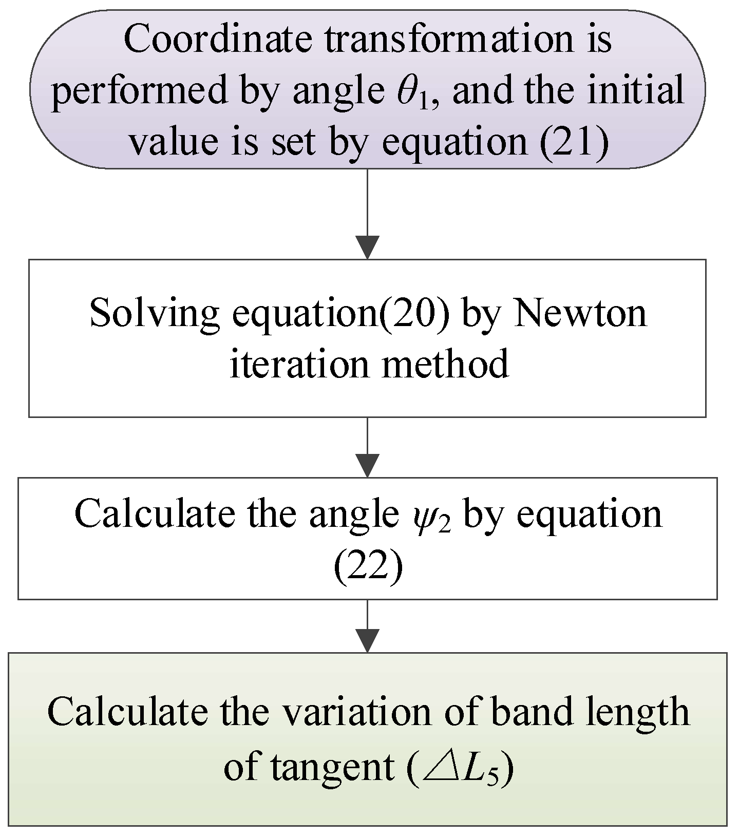
2.2.3. Method for Calculating Arc Length of Elliptical Pulley in Any Phase and Rotational Angle

In Section 2.1.1, Equation (1), used for calculating the longitudinal elongation ( Δ i ) of the belt span, contains the integral term 0 t R 1 θ ˙ 1 d σ , which is the arc length of the rotation of the elliptical pulley with a running time t. The integral operation will greatly increase the iterative solving time and reduce the solving efficiency. Therefore, an analytical solution of the integral operation is given here.
Figure 7 shows the position of the elliptical pulley after a clockwise angle θ 1 . Its tangent point changes from P c to P c . It can be seen that the rotation arc length of the elliptical pulley in the integral term 0 t R 1 θ ˙ 1 d σ is P c P c . The radius corresponding to the tangent point P c and the tangent point P c are R 1 ( 0 ) and R 1 ( t ) , respectively. The relative angles between the two tangent points and the long axis of the elliptical pulley R a are θ 0 and θ 0 + θ 1 , respectively.
When the major axis of the ellipse is located on the horizontal X-axis (as shown in Figure 4), the parameter equation of the ellipse can be expressed as
x = R a cos ( φ e ) y = R b sin ( φ e )
where φ e is the centrifugal angle between the axis of the tangent point and the long axis, with a value interval of φ e [ 0 , 2 π ] .
According to the arc length formula, when the centrifugal angle of the ellipse changes from 0 to φ e , the corresponding arc length of the ellipse is
0 t R 1 θ ˙ 1 d σ = L s = 0 φ e R a 2 sin 2 ( φ e ) + R b 2 cos 2 ( φ e ) d φ e
The eccentricity e e is assumed to be
e e = R a 2 R b 2 R a
The arc length in Equation (24) can be simplified to an integral formula with eccentricity as follows:
0 t R 1 θ ˙ 1 d σ = L s = R a 0 φ e 1 e e 2 c o s 2 ( φ e ) d φ e
By the recurrence formula of the cosine function, Equation (26) can be converted into [23]
0 t R 1 θ ˙ 1 d σ = L s = R a φ e a φ R a 2 sin ( φ e ) f ( φ e )
where a φ and f ( φ e ) are a constant term and a function with an independent variable of φ e , respectively. The expression is given below. Equations (28) and (29) are cited from references [28,29].
a φ = 1 n = 1 N ( 2 n 1 ) ! ! ( 2 n ) ! ! 2 · e e 2 n 2 n 1
f ( φ e ) = n = 1 N ( 2 n 1 ) ! ! ( 2 n ) ! ! 2 · e e 2 n 2 n 1 m = 1 n ( 2 m 2 ) ! ! ( 2 m 1 ) ! ! cos 2 m 1 ( φ e )
where n and m are the rows and columns of the matrix, respectively; N can be any positive integer. Here, the value of N is ten.

2.3. Vibration Response Solution of Belt Drive System

The order excitation of belt drive system is expressed as [1,2]
θ ˙ 1 = 2 π N 60 + k A k ( N ) cos [ k 2 π N 60 t + φ k ( N ) ]
where k , φ k ( N ) , and A k ( N ) indicate the order, phase, and amplitude of the excitation, respectively; N denotes the crankshaft’s mean rotational velocity in unit r·min−1.
Based on Equation (1), the dynamic equations of the belt drive system can be expressed as
I θ ¨ + C θ ˙ + K θ + F 1 + F 2 = 0
where I , C , K , and θ are the matrices of the moments of inertia, damping, stiffness, and angular displacement, which are given in Equations (32)–(35); F 1 and F 2 are the loaded matrices and the torque caused by the movement of the tensioning arm, which are given in Equations (35)–(39).
θ = θ 2 , θ 3 , θ 4 , θ 5 , θ t T
I = d i a g ( I 2 , I 3 , I 4 , I 5 , I 5 + I t )
C = d i a g ( C 2 , C 3 , C 4 , C 5 , C e q )
K = ( K 1 + K 2 ) R 1 2 K 2 R 2 R 3 0 0 0 K 2 R 2 R 3 ( K 2 + K 3 ) R 2 2 K 3 R 3 R 4 0 0 0 K 3 R 3 R 4 ( K 3 + K 4 ) R 3 2 K 4 R 4 R 5 K 4 R 4 L t sin β 1 0 0 K 4 R 4 R 5 ( K 4 + K 5 ) R 4 2 ( K 4 sin β 1 K 5 sin β 2 ) R 5 L t 0 0 K ˜ 4 K ˜ 5 K ˜ t
F 1 = M ¯ 2 , M ¯ 3 , M ¯ 4 , M ¯ 5 , Q t T
F 2 = K 1 R 2 0 t R 1 θ ˙ 1 d σ , 0 , K 4 R 4 L t θ t 0 s i n β 1 , K 4 s i n β 1 + K 5 s i n β 2 R 5 L t θ t 0 K 5 R 5 0 t R 1 θ ˙ 1 d σ , F t T
The integral term 0 t R 1 θ ˙ 1 d σ in Equation (30) can be calculated into analytical expression by Equation (27). The expressions of K ˜ 4 , K ˜ 5 , K ˜ t , M ¯ i , and F t in Equations (32)–(33) are
K ˜ 4 = K 4 R 4 L t sin β 1 + K 4 R 4 R 5
K ˜ 5 = ( K 4 sin β 1 K 5 sin β 2 ) R 5 L t ( K 4 + K 5 ) R 5 2
K ˜ t = K e q + ( K 4 sin 2 β 1 + K 5 sin 2 β 2 ) L t 2 + ( K 4 sin β 1 + K 5 sin β 2 ) R 5 L t
M ¯ i = M i R i ( T ( i 1 ) 0 T i 0 ) , i = 2 , 3 , 4 , 5
F t = K 5 L t s i n β 2 0 t R 1 θ ˙ 1 d σ + K 5 R 5 0 t R 1 θ 1 d σ K e q θ t 0 K 4 s i n 2 β 1 + K 5 s i n 2 β 2 L t 2 θ t 0 K 4 s i n β 1 + K 5 s i n β 2 R 5 L t θ t 0
where T i 0 is the initial tension of the ith belt span.
The belt drive system is excited by a sinusoidal excitation; then the angular displacements of the pulleys and the tensioning arm are described as
θ j = θ ¯ j + φ j = ω ¯ j t + φ j , j = 2 , 3 , 4 , 5
θ t = θ t 0 + φ t
where φ j and φ t are the oscillation angular displacement for each pulley and the tensioning arm; θ ¯ i is the angular displacement if the angular velocity is ω ¯ j .
According to Equations (43) and (44), the dynamic equation can be change to
I Φ ¨ + C Φ ˙ + K Φ + F ˜ 1 + F ˜ 2 = 0
The matrices in Equation (45) are given as below.
Φ = φ 2 , φ 3 , φ 4 , φ 5 , φ t T
F ˜ 1 = M 2 , M 3 , M 4 , M 5 , 0 T , F ˜ 2 = 0 , 0 , 0 , K 5 R 1 R 5 φ 1 , F ˜ t T F ˜ 2 = K 1 R 2 R 1 φ 1 + R 1 Δ θ ˙ 1 d σ , 0 , 0 , K 5 R 1 R 5 φ 1 , F ˜ 1 T
where F ˜ t is the torque caused by the oscillation of tensioning arm φ t .
F ˜ t = K 5 L t s i n β 1 R 1 φ 1 + 0 t R 1 Δ θ ˙ 1 d σ + K 5 R 5 0 t R 1 Δ θ ˙ 1 d σ
where the integral term 0 t R 1 θ ˙ 1 d σ can be calculated as an analytical expression by Equation (27).
According to reference [28], a Harmonic incremental balance method with the Quasi-Newton method is applied to evaluate the system’s dynamic responses.

3. Analysis of Dynamic Performance of System with Elliptical Pulley

According to the method stated in Section 2, the system’s performance with an elliptical crankshaft pulley will be analyzed in this section. The parameters of the tensioner, system, and belt are shown in Table A1, Table A2, Table A3 and Table A4 of the Appendix A. The rotational vibration of the crankshaft is obtained and shown in Figure A1 of Appendix A. The rotational vibration of the crankshaft is mainly of the second order. The load of camshafts is periodic, as shown in Figure A2 of Appendix A.

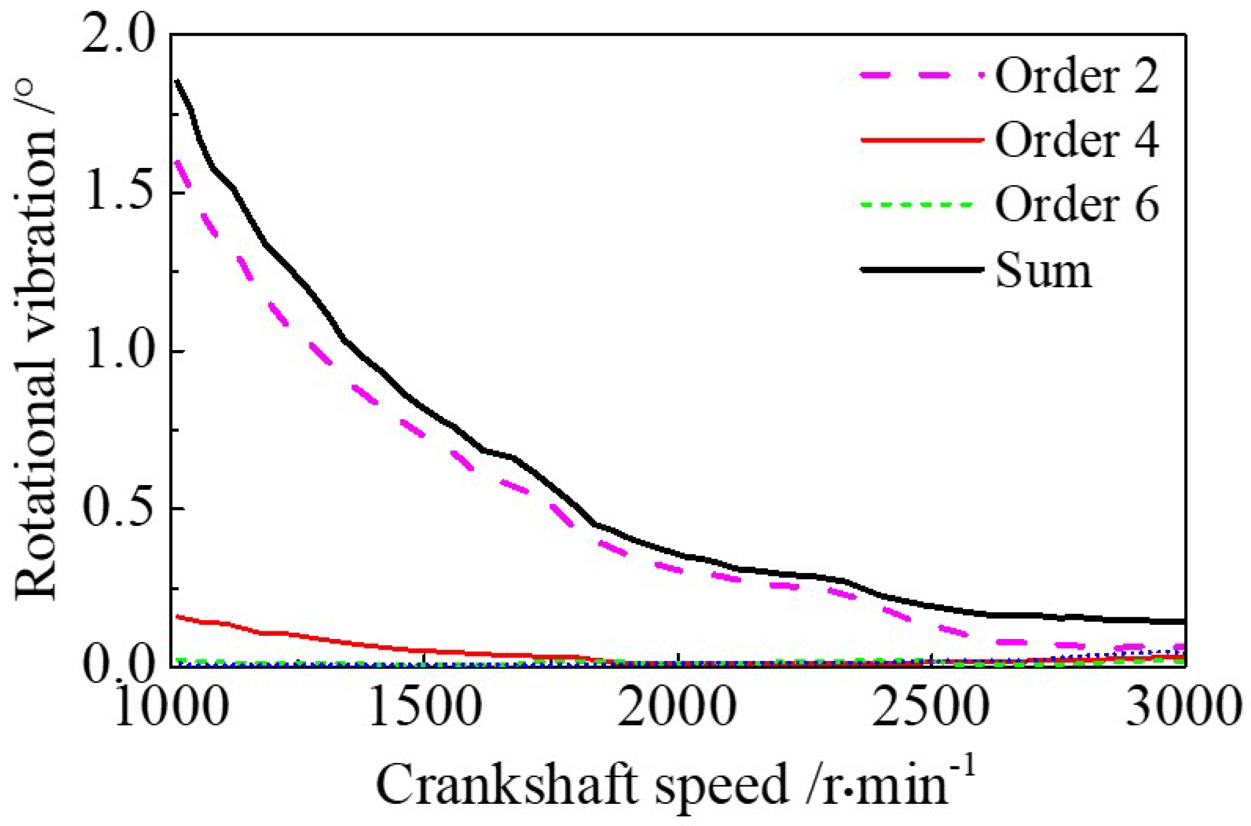
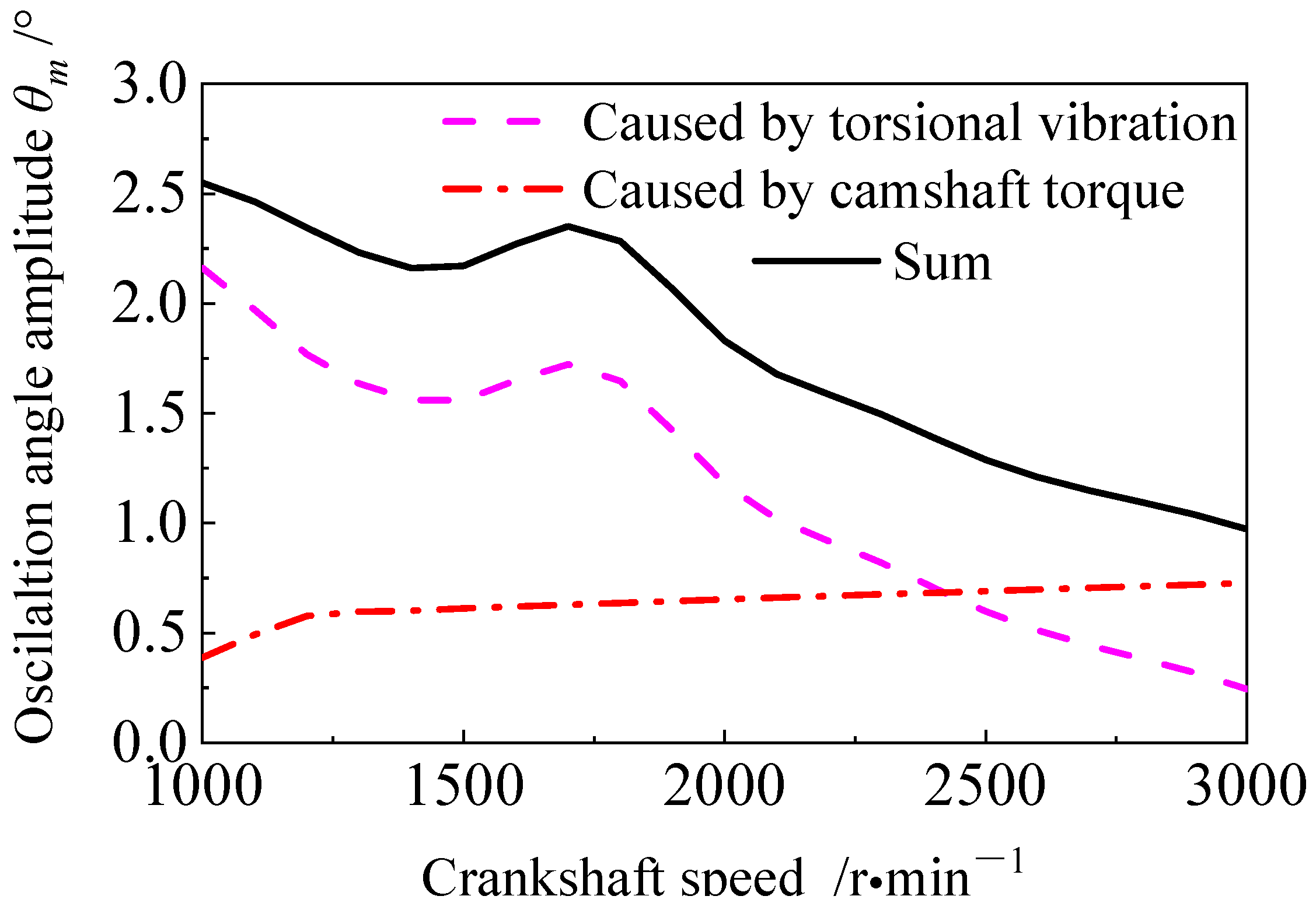
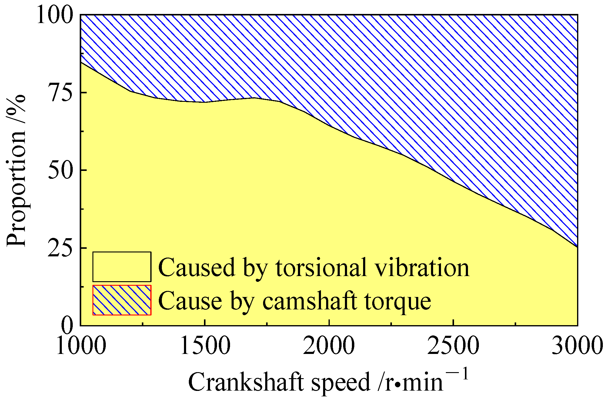
3.1. The Component Analysis of Oscillation Angle Amplitude of Tensioning Arm

The oscillation amplitude of the tensioning arm θ m can comprehensively reflect the dynamic performance of the system, such as the belt tension variation, the transmission error between the driving pulley, and the driven pulley. The smaller the oscillation amplitude θ m , the smaller the variation in the working torque of the tensioner, the smaller the belt tension variation, and the more accurate the transmission. According to the crankshaft rotational vibration excitation and camshaft load, as given in Figure A1 and Figure A2 of Appendix A, the generation source of the oscillation angle amplitude of the tensioning arm at each speed with a regular circular crankshaft pulley are analyzed, as shown in Figure 8.
In Figure 8, the oscillation angle of the tensioning arm is mainly caused by the low-excitation speed crankshaft rotational vibration. With the increase in rotational speed, the amplitude of the oscillation angle of the tensioning arm caused by rotational vibration gradually decreases. This is because the rotational vibration of the crankshaft decreases at a higher speed. The amplitude of the oscillation angle of the tensioning arm caused by the camshaft load increases slightly with the rotation speed. The reason for this is that the camshaft load changes very little with the rotation speed. At the same time, the damping value of the tensioner decreases at a higher speed.
Figure 9 shows the proportion of the oscillation angle of the tensioning arm. It is seen that the proportion of the oscillation angle of the tension arm caused by rotational vibration decreases at a higher crankshaft speed, while the proportion of the tensioning arm caused by load increases.

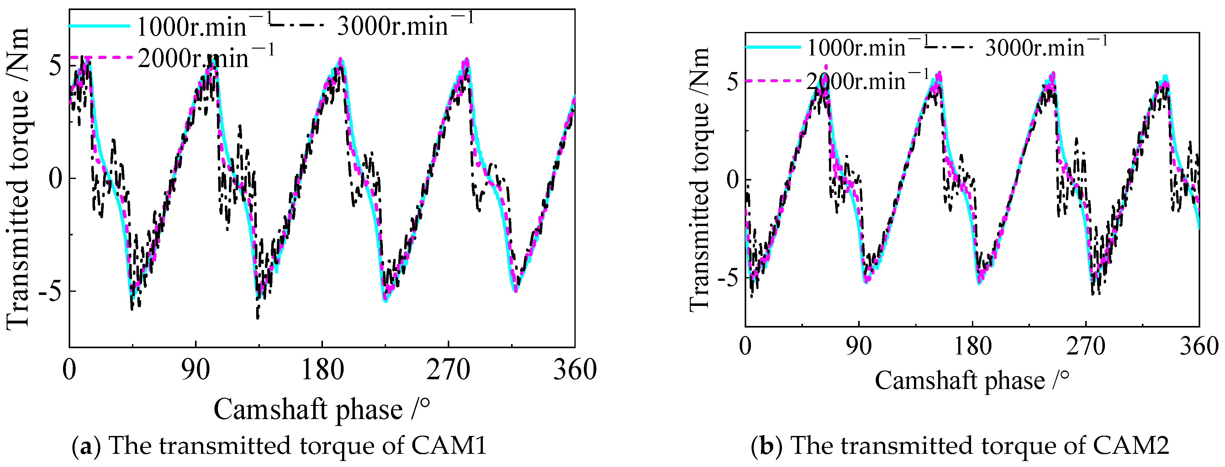
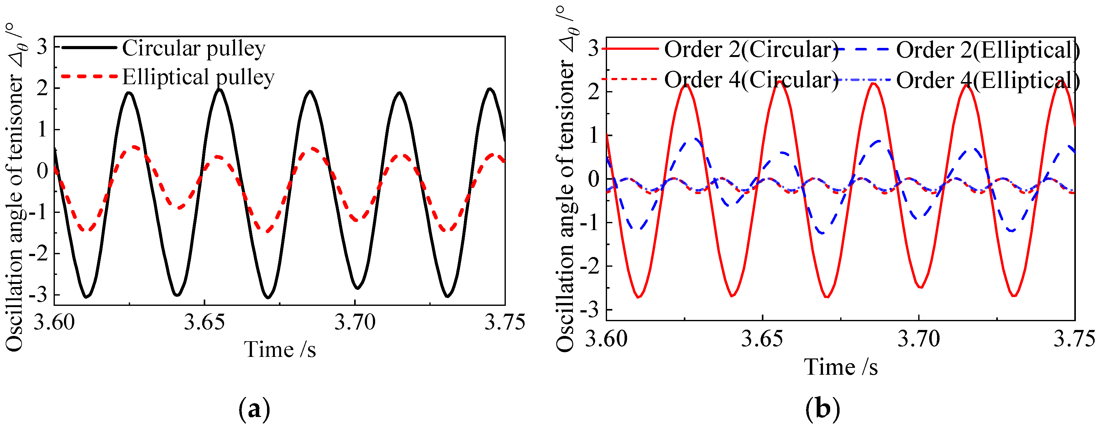
3.2. The Analysis Results of System Dynamic Response at the Typical Speed

In order to improve the dynamic performance, the initial phase θ c and eccentricity δ c of the elliptical pulley need to be analyzed. According to Figure A1, the rotational vibration is high at a crankshaft speed of 1000 r·min−1. Thus, here this speed is chosen as the typical condition. The excitation parameters are shown in Table 1.
Figure 10 shows the effect of different initial elliptical pulley phase angles on the performance of the tensioning arm. It can be seen from Figure 9 that with an increasing phase angle, the oscillation angle decreases first, then increases, and finally decreases. And the difference between the peak and trough value is 90°. It can be seen from Table 1 that the primary excitation of the crankshaft pulley is of the second order, and the phase angle is 45.18°. When the initial phase angle is 45°, it can just offset the second-order excitation. When the initial phase angle is 135°, the excitation peak value of the system is magnified.
Figure 11 shows the influence of the pulley eccentricity on the oscillation angle of the tensioning arm. With an increase in eccentricity, the oscillation angle amplitude of the tensioning arm first decreases and then increases, and the eccentricity corresponding to the trough position is about 0.12. If the eccentricity is too small, the rotational excitation of the elliptical pulley is not enough to offset the torsional excitation of the system. If the eccentricity is too large, there will be an additional second-order excitation. Thus the oscillation angle of the tensioning arm shows an increasing trend.
Figure 12 shows the angular displacement oscillation of the driven pulley (camshaft pulley) under two schemes of circular and elliptical crankshaft pulleys. If the circular pulley is adopted, the angular fluctuation amplitude of the camshaft pulley is about half of that of the crankshaft pulley because the radius of the camshaft pulley is twice that of the crankshaft. The angular oscillation amplitude of the camshaft pulley decreases because the second-order excitation of the crankshaft is partially offset. However, due to the use of the elliptical pulley, the tight side belt of the camshaft pulley produces regular elongation and shortening changes, which leads to certain angular displacement fluctuations in the camshaft pulley.
Figure 13 shows the comparative response of the tensioning arm under the two schemes. In Figure 13a, the comparative amplitude of the tensioning arm is greatly reduced with the elliptical pulley because the main exciting rotational vibration of the crankshaft is offset. However, the camshaft load still exists, and it makes the tensioning arm change regularly, as shown in Figure 8. The changes in the load of the camshaft are of the second order, with a transmission ratio as shown in Figure A2 of Appendix A. Thus the oscillation angle of the tensioning arm also presents as being of the second order, as shown in Figure 13b. In addition, the fourth-order amplitude of the oscillation angle of the tensioning arm is basically the same.

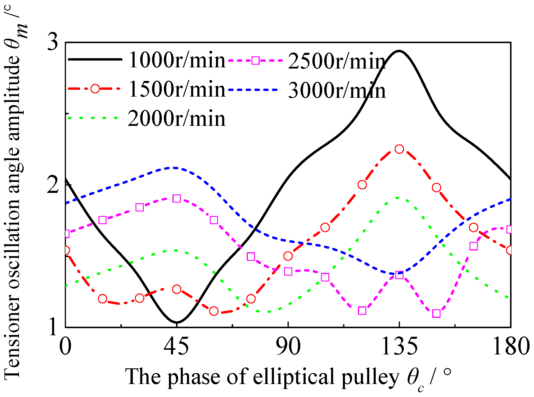
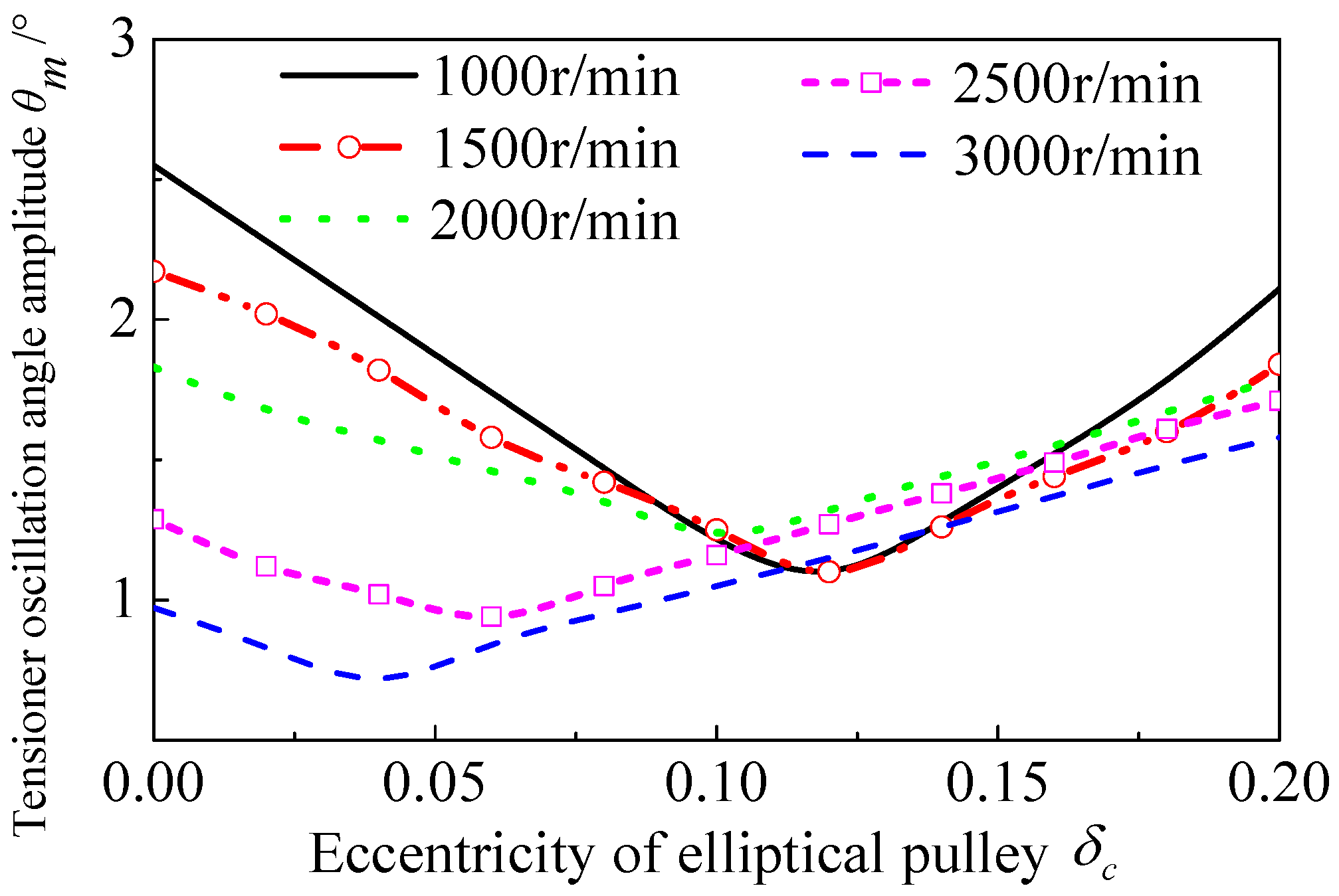
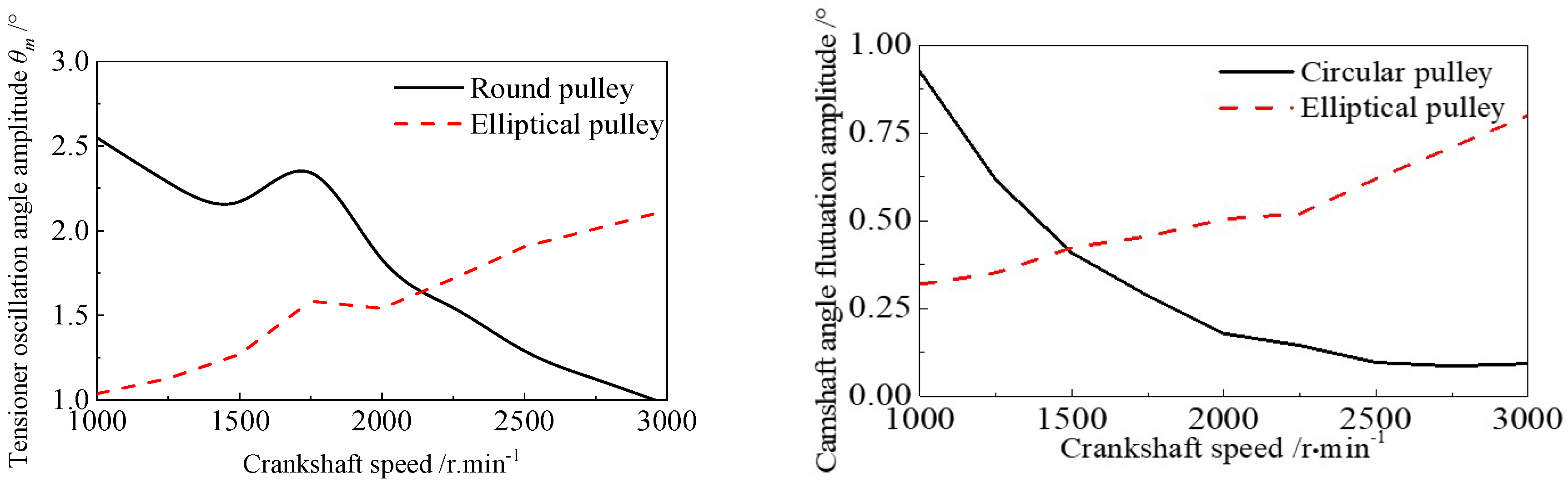
3.3. The Analysis Results of System Dynamic Response Versus Different Speeds

Figure 14 shows the effect of the phase angle of the elliptical pulley on the oscillation angle of the tensioning arm at different speeds. Owing to the different amplitudes of crankshaft rotational vibration under the same eccentricity, the variation in the oscillation amplitude of tensioning arm is distinct.
The rotational vibration amplitude of the crankshaft is large at a low speed of 1000–1500 r·min−1. With a phase angle of 45° for the elliptical pulley, the rotational vibration of the crankshaft is basically offset, so the oscillation angle is small. When the rotating speed is high, at a range 2000–3000 r·min−1, the rotational vibration amplitude of the crankshaft becomes small. Thus the vibration will be excited by the elliptical pulley with an angle 45°; then, the oscillation angle of the tensioning arm increases instead.
On the contrary, if the phase of the elliptical pulley is 135°, the rotational vibration of the crankshaft is amplified and the oscillation of the tensioning arm increases. On the other hand, the load of the camshaft at high speed is the main factor for the oscillation. When the phase of the elliptical pulley is in the range of 90~135°, the load of the camshaft is partially compensated for with the elliptic excitation. Thus the oscillation of the tensioning arm is reduced.
Figure 15 shows the effect of the eccentricity of the elliptical pulley on the oscillation angle response of the tensioning arm versus the speed. With a larger excitation speed, the trough value of the oscillation angle moves towards the position of a smaller eccentricity of the ellipse. This is because, the higher the crankshaft speed, the smaller the rotational vibration amplitude and the smaller the elliptical eccentricity required to offset rotational vibration. With the further increase in eccentricity, the oscillation amplitude of the tensioning arm will also increase, because the elliptical pulley adds additional speed fluctuation excitation to the system.
Figure 16a shows the comparison of the oscillation angle amplitude of the tensioning arm of the two schemes versus the speed. At a low speed range, the elliptical pulley can offset part of the rotational vibration and reduce the tensioning arm oscillation. As the rotating speed increases, the rotational vibration amplitude decreases, and the elliptical pulley will amplify the rotational vibration and increase the oscillation of the tensioning arm.
Figure 16b shows the comparison of the angular displacements of the camshaft for the two schemes. At a low speed range, the angular displacement fluctuation of the camshaft is smaller than that of the scheme using a circular pulley. With a higher speed, the angular displacement fluctuation of the camshaft increases instead. This is because the elliptical pulley excites a larger speed fluctuation, which increases the angular displacement fluctuation of the camshaft.

4. System Vibration Response Test and Verification of the Method

4.1. Test Rig for Dynamic Response of System

A test bench rig is applied to evaluate the system’s dynamic performance, as shown in Figure 17.
In Figure 17, the angular displacement and velocity of the pulley are measured by angle encoders (2) under different crankshaft speeds. And the speed fluctuation can be obtained and transferred to the angle value to compare against its average rotational speed [1]. The transmission error between the driving pulley and driven pulley is defined as follows:
ε i j = θ i R j θ j / R i
where i and j are the number of the pulleys.

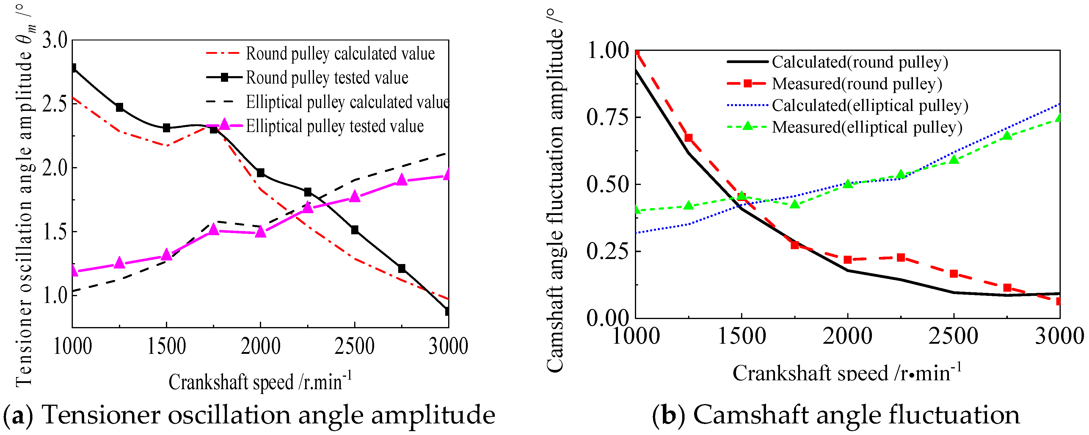
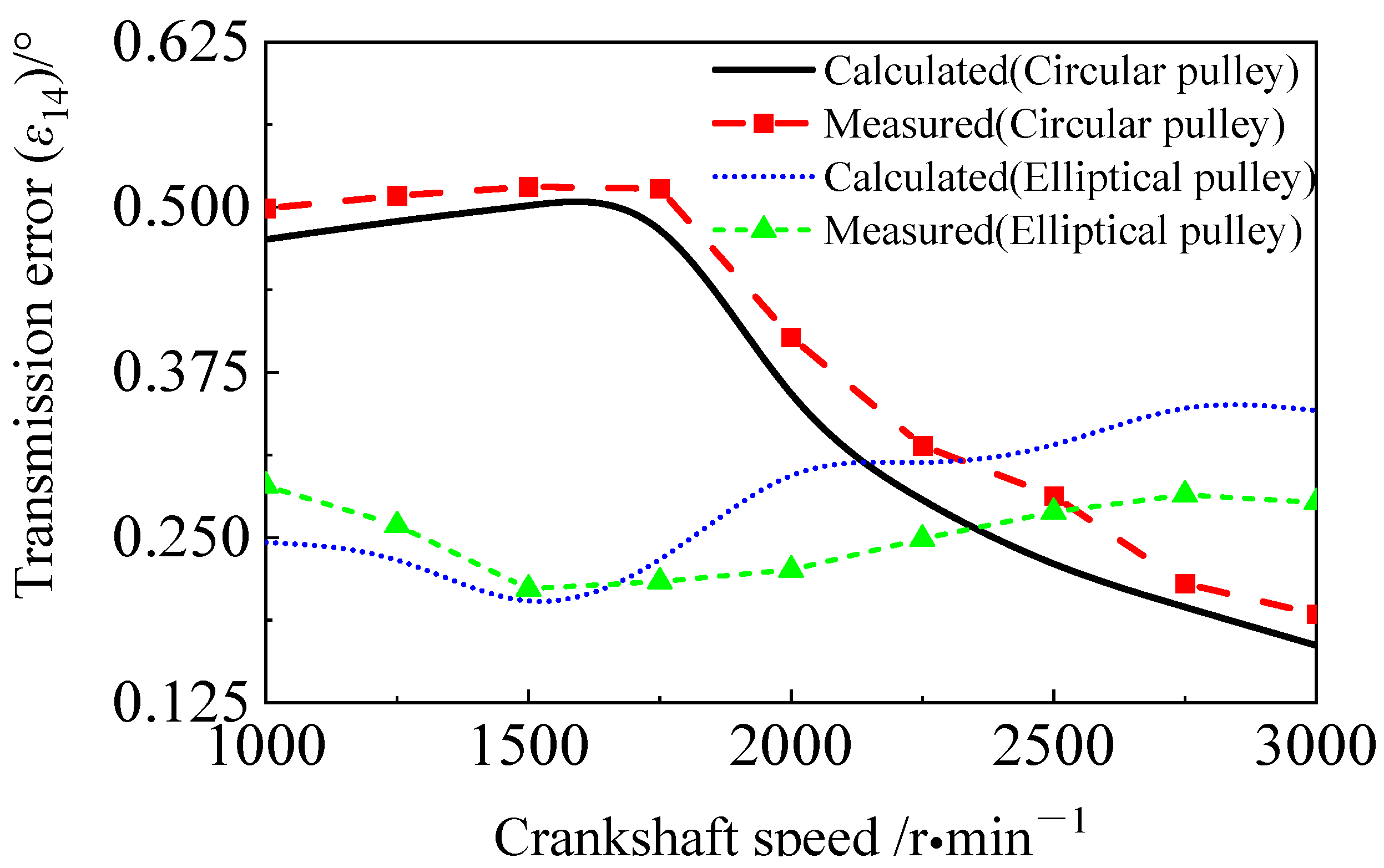
4.2. Verification for Dynamic Response of System

Figure 18 shows the tensioner oscillation angle and the fluctuation amplitude of the camshaft under the two schemes of the elliptical pulley and circular pulley. It can be seen from Figure 18a that the oscillation angle amplitude of the tensioner in the circular pulley scheme gradually decreases with a larger rotational speed. This is because the amplitude of the rotational vibration decreases as the rotational speed increases. For the elliptical pulley scheme, the tensioner oscillation angle increases with a larger rotational speed, but its changing trend is gentler. Meanwhile, at low rotational speeds, its amplitude is smaller than that of the circular pulley scheme. The overall average amplitude of the elliptical pulley scheme is smaller than that of the circular pulley scheme. Moreover, in the low-speed scenarios where the usage proportion is relatively large, the amplitude of the oscillation angle is smaller, indicating that the tension fluctuation is more stable. Similarly, the angle fluctuation trend of the driven pulley CAM1 shown in Figure 18b is also the same as that of the tensioning arm.
Figure 19 shows the transmission error between the driving pulley crankshaft (CRK) and the driven pulley camshaft 2 (CAM2). It can be seen that the amplitude of the transmission error of the circular pulley scheme shows a rapid decreasing trend if the crankshaft speed is larger than 1750 r·min−1. The average error of the circular pulley at all rotational speeds is 0.383° (measured value). For the elliptical pulley scheme, the transmission error changes are gentler than those of the circular pulley scheme. The transmission error shows an upward trend when the rotational speed is greater than 1500 r·min−1. The average error of the elliptical pulley at all rotational speeds is 0.253° (measured value).
As the operating time of the system increases, the belt will show wear and elongation, and the performance of the tensioner will decline. The descriptions of these two scenarios are shown in Table 2. These factors are also considered for analysis, and the results are shown in Figure 20 and Figure 21.
For the circular pulley scheme in Figure 20, when the performance declines, as in Case I and Case II, the oscillation angle amplitude of the tensioner increases by a value 0.4–0.5° compared with the initial performance. For the elliptical pulley scheme, the increases in the oscillation angle amplitude of the tensioner are all within 0.3°. Moreover, when the crankshaft excitation speed is below 1750 r·min−1, the amplitude of the tensioner oscillation angle does not vary much. Similarly, under the elliptical pulley scheme, the variation amplitude and average transmission error are smaller than those under the circular pulley scheme.

5. Conclusions

A modeling and analytical calculation method for a toothed belt drive system with an elliptical driving pulley is presented in this paper, and the method is verified by a test bench rig. The variation law of the system response is analyzed.
The conclusions are drawn as follows: (1) If the initial phase angle of the elliptical pulley aligns with the phase of order excitation, it generates opposing rotational speed fluctuation excitations that counteract the second-order crankshaft excitation components. (2) With a larger eccentricity of the elliptical pulley, the dynamic performance is first better and then worse. (3) With a larger crankshaft speed, the trough value of the response of the oscillation angle of the tensioning arm moves to the position where the eccentricity of the ellipse is small. (4) When the system performance declines, such as the tension decreasing or the performance of the energy-absorbing components weakening, the adoption of the elliptical pulley scheme can better maintain the stability of the system response and maintain better transmission accuracy.

Author Contributions

S.L.: Supervision, funding acquisition. Y.Z.: Writing, research concept and design. Z.Z.: Writing—original draft, methodology. F.C.: Validation, ingestigation. Z.L.: Writing, data analysis and interpretation. All authors have read and agreed to the published version of the manuscript.

Funding

This research was funded by [the National Natural Science Foundation of China] grant number [No. 52205090].

Data Availability Statement

Data is contained within the article.

Conflicts of Interest

The authors declare that they have no conflicts of interest.

Appendix A

Table A1. The geometrical parameters of the tensioner.
SymbolParameterValue Unit
(xp, yp)Pivot position(−7.976, 159.114)mm
L t Tensioning arm’s length5mm
θ t Angular displacement of the tensioning arm in the initial equilibrium position75.82°
α t Zero torque angular displacement of tensioning arm0.80°
I t Moment of inertial for the tensioning arm turning around the pivot7.9 × 10−6kg·m2
Table A2. The coordinate, radius, and moments of inertia and damping for each pulley.
Type Coordinate ,   x i , y i (mm) Radius ,   R i (mm) Moment   of   Inertial ,   I i (kg·m2) Damping ,   C i (Nms/°)
CRK(0, 0)28.803 (Circular)0.02760.0001
CAM1(55.40, 321.25)57.6060.0020.0001
CAM2(−62.50, 321.25)57.6060.0020.0001
TEN-32.7000.0004170.0001
Table A3. The timing belt parameters.
SymbolParameterValueUnit
E b Elasticity modulus5107MPa
T 0 The belt pretension215N
δ 1 Angle between belt tensions T 1 and T 2 162.81°
ψ 1 Angle from the fourth belt span to the negative X-axis in anticlockwise orientation220.67°
ψ 2 Angle from the fifth belt span to the negative X-axis in the anticlockwise orientation110.96°
Table A4. The tensioner parameters.
SymbolParameterMeasurementUnit
K l Loading stiffness0.0218Nm/°
K u Unloading stiffness0.0133Nm/°
K s Spring stiffness0.00165
K θ Lag stiffness0.612Nm/°
θ f Lag angle0.518°
M f Friction torque0.317Nm
Figure A1. The rotational vibration amplitude of the crankshaft versus speed.
Actuators 14 00371 g0a1
Figure A2. The transmitted torque versus the camshaft phase for various crankshaft speeds.
Actuators 14 00371 g0a2

References

  1. Long, S.; Zhao, X.; Shangguan, W.B.; Zhu, W. Modeling and Validation of Dynamic Performances of Timing Belt Driving Systems. Mech. Syst. Signal Process. 2020, 144, 106910. [Google Scholar] [CrossRef]
  2. Long, S.; Huang, W.; Wang, J.; Liu, J.; Gu, Y.; Wang, Z. A Fixed-Time Consensus Control with Prescribed Performance for Multi-Agent Systems Under Full-State Constraints. IEEE Trans. Autom. Sci. Eng. 2025, 22, 6398–6407. [Google Scholar] [CrossRef]
  3. Wang, J.; Wu, Y.; Chen, C.L.P.; Liu, Z.; Wu, W. Adaptive PI Event-Triggered Control for MIMO Nonlinear Systems with Input Delay. Inf. Sci. 2024, 677, 120817. [Google Scholar] [CrossRef]
  4. Wang, J.; Li, Y.; Wu, Y.; Liu, Z.; Chen, K.; Chen, C.L.P. Fixed-Time Formation Control for Uncertain Nonlinear Multi-Agent Systems with Time-Varying Actuator Failures. IEEE Trans. Fuzzy Syst. 2024, 32, 1965–1977. [Google Scholar] [CrossRef]
  5. Shangguan, W.B.; Zeng, X. Modeling and validation of rotational vibration responses for accessory drive system-Part II: Simulations and Analyses. ASME J. Vib. Acoust. 2013, 135, 031003. [Google Scholar] [CrossRef]
  6. Zhu, H.; Zhu, W.; Fan, W. Dynamics modeling, simulation and experiment of power transmission belt drives: A systematic review. J. Sound Vib. 2020, 491, 115759. [Google Scholar] [CrossRef]
  7. Liu, X.; Tan, J.; Long, S. Multi-axis fatigue load spectrum editing for automotive components using generalized S-transform. Int. J. Fatigue 2024, 188, 108503. [Google Scholar] [CrossRef]
  8. Ding, H.; Li, D. Static and dynamic behaviors of belt-drive dynamic systems with a one-way clutch. Nonlinear Dyn. 2014, 78, 1553–1575. [Google Scholar] [CrossRef]
  9. Bastien, J.; Michon, G.; Manin, L.; Dufour, R. An analysis of the modified Dahl and Masing models: Application to a belt tensioner. J. Sound Vib. 2007, 302, 841–864. [Google Scholar] [CrossRef]
  10. Wan, J.; Gong, Q.; Huang, K.; Liu, Z.; Chen, C.L.P.; Liu, J. Event-Triggered Prescribed Settling Time Consensus Compensation Control for a Class of Uncertain Nonlinear Systems with Actuator Failures. IEEE Trans. Neural Netw. Learn. Syst. 2023, 34, 5590–5600. [Google Scholar]
  11. Zhu, F.; Parker, R.G. Non-linear dynamics of a one-way clutch in belt–pulley systems. J. Sound Vib. 2005, 279, 285–308. [Google Scholar] [CrossRef]
  12. Zhu, F.; Parker, R.G. Influence of Tensioner Dry Friction on the Vibration of Belt Drives With Belt Bending Stiffness. ASME J. Vib. Acoust. 2008, 130, 1161–1171. [Google Scholar] [CrossRef]
  13. Ludovico, D.; Guardiani, P.; Lasagni, F.; Lee, J.; Cannella, F.; Caldwell, D.G. Design of Non-Circular Pulleys for Torque Generation: A Convex Optimisation Approach. IEEE Robot. Autom. Lett. 2021, 6, 958–965. [Google Scholar] [CrossRef]
  14. Cheng, G.; Zu, J.W. Nonstick and stick-slip motion of a coulomb-damped belt drive system subjected to multifrequency excitations. ASME J. Appl. Mech. 2003, 70, 871–884. [Google Scholar] [CrossRef]
  15. Long, S.; Zhao, X.; Shangguan, W.B. Method for estimating vibration responses of belt drive systems with a nonlinear tensioner. Nonlinear Dyn. 2020, 100, 2315–2335. [Google Scholar] [CrossRef]
  16. Zhu, H.; Hu, Y.; Zhu, W. Modification of natural frequencies of an automotive belt drive system based on eigen-sensitivity analysis of its configuration parameters. Eur. J. Mech.-A/Solids 2018, 67, 137–156. [Google Scholar] [CrossRef]
  17. Hou, Z.; Wang, X.; Lao, Y. Frequency Sensitivity Analysis of Multi-ribbed Belt Drive System. J. Mech. Eng. 2009, 45, 235–239. [Google Scholar] [CrossRef]
  18. Zhu, H.; Hu, Y.; Zhu, W.; Pi, Y. Optimal design of an autotensioner in an automotive belt drive system via a dynamic adaptive PSO-GA. ASME J. Mech. Des. 2017, 139, 093302. [Google Scholar] [CrossRef]
  19. Zhu, H.; Hu, Y.; Zhu, W.; Fan, W.; Zhou, B.W. Multi-objective design optimization of an engine accessory drive system with a robustness analysis. Appl. Math. Model. 2020, 77, 1564–1581. [Google Scholar] [CrossRef]
  20. Coppola, G.; Boyes, A.M.; Spicer, G. Synchronous drive apparatus with adjustable non-circular drive elements. U.S. Patent 10,767,516, 8 September 2020. [Google Scholar]
  21. Wölfle, F.; Kaufhold, T.; Hagemann, K.; Maier, S. Simulationsprogramm zur Vorhersage der dynamischen Vorgänge in Nebenaggregate-Antrieben mit Keilrippenriemen. MTZ-Mot. Z. 2003, 64, 414–421. (In German) [Google Scholar] [CrossRef]
  22. Wang, X.; Zhu, W. Dynamic analysis of an automotive belt-drive system with a noncircular sprocket by a modified incremental harmonic balance method. ASME J. Vib. Acoust. 2017, 139, 011009. [Google Scholar] [CrossRef]
  23. Zhu, H.; Zhu, W.; Hu, Y. Periodic response of a timing belt drive system with an oval cogged pulley and optimal design of the pitch profile for vibration reduction. ASME J. Comput. Nonlinear Dyn. 2018, 13, 011014. [Google Scholar] [CrossRef]
  24. Li, J. Eccentric sprocket technology applied to engine timing system. Intern. Combust. Engine Power Plant 2018, 35, 39–44. (In Chinese) [Google Scholar]
  25. Liang, S.; Li, Z.; Li, Y.; Hu, J.; Yang, W.; Lan, J.; Wang, R. Non circle belt pulley dynamic calculate by EXCITE_TD. Automob. Appl. Technol. 2017, 2, 29–31. (In Chinese) [Google Scholar]
  26. Chen, J.; Ye, J.; Wang, Y.; Sun, X.; Xia, X.; He, X. Design, modeling and experiment of a novel synchronous belt drive with noncircular pulleys. Iran. J. Sci. Technol. Trans. Mech. Eng. 2020, 44, 533–542. [Google Scholar] [CrossRef]
  27. Long, S.; Wang, W.; Yue, X.; Zhang, C. Dynamic modeling of the belt drive system with an equivalent tensioner model. J. Vib. Eng. Technol. 2022, 10, 511–525. [Google Scholar] [CrossRef]
  28. Barnard, R.W.; Pearce, K.; Richards, K.C. A Monotonicity Property Involving 3 F 2 and Comparisons of the Classical Approximations of Elliptical Arc Length. SIAM J. Math. Anal. 2000, 32, 403–419. [Google Scholar] [CrossRef]
  29. Feng, Y. Series expansion and approximate treatment for elliptic arc length. Coll. Math. 2018, 195, 110–114. (In Chinese) [Google Scholar]
Figure 1. Layout of belt drive system with an elliptical crankshaft pulley.
Actuators 14 00371 g001
Figure 2. Hysteretic model and linearized model of the tensioner.
Actuators 14 00371 g002
Figure 3. Layout of position and angle change in elliptical crankshaft pulley with time t.
Actuators 14 00371 g003
Figure 4. Tangent diagram between crankshaft elliptical pulley and tensioning pulley.
Actuators 14 00371 g004
Figure 5. The tangent diagram of the elliptical pulley and tensioning pulley with any rotation angle. (a) Tangent span between elliptical pulley and tensioning pulley at any rotation angle. (b) The schematic diagram of coordinate transformation. (The red axis corresponds to the direction of the major and minor axes of the current elliptical wheel.)
Actuators 14 00371 g005
Figure 6. Calculation process of variation in belt length caused by tensioner oscillation.
Actuators 14 00371 g006
Figure 7. The tangent point position after a rotation angle θ1 of the elliptical pulley.
Actuators 14 00371 g007
Figure 8. The oscillation angle amplitude of the tensioning arm versus speed with a circular crankshaft pulley.
Actuators 14 00371 g008
Figure 9. The proportion of oscillation angle of the tensioning arm versus crankshaft speed.
Actuators 14 00371 g009
Figure 10. The influence of different initial elliptical pulley phase angles on the oscillation angle response of the tensioning arm ( δ c = 0.12).
Actuators 14 00371 g010
Figure 11. The influence of the eccentricity of the elliptical pulley on the oscillation angle of the tensioning arm ( θ c = 45°).
Actuators 14 00371 g011
Figure 12. The angular displacement fluctuation of the camshaft under two schemes ( δ c = 0.12, θ c = 45°).
Actuators 14 00371 g012
Figure 13. The oscillation angle response of tensioning arm under two schemes ( δ c = 0.12, θ c = 45°). (a) The oscillation angle of the tensioning arm. (b) The oscillation angle of each order of the tensioning arm.
Actuators 14 00371 g013
Figure 14. The influence of different initial phase angles of elliptical pulleys on the oscillation angle of the tensioning arm ( δ c = 0.12).
Actuators 14 00371 g014
Figure 15. The influence of different eccentricity on the response of the oscillation angle of the tensioning arm ( θ c = 45°).
Actuators 14 00371 g015
Figure 16. The oscillation angle of the tensioning arm and the angular fluctuation of the camshaft under two schemes ( δ c = 0.12, θ c = 45°).
Actuators 14 00371 g016
Figure 17. Test rig to evaluate the dynamic performances of the timing belt system. 1—laser displacement sensor; 2—angle encoder; 3—pressure sensor.
Actuators 14 00371 g017
Figure 18. The tensioning arm’s oscillation angle and camshaft fluctuation versus the crankshaft speed for the two schemes.
Actuators 14 00371 g018
Figure 19. The peak to peak value of the transmission error between the camshaft (CAM2) and the crankshaft (CRK).
Actuators 14 00371 g019
Figure 20. The tensioning arm’s oscillation angle versus the crankshaft speed for the different schemes.
Actuators 14 00371 g020
Figure 21. The transmission error versus the crankshaft speed for the different schemes.
Actuators 14 00371 g021
Table 1. The excitation parameter of a crankshaft at a speed of 1000 r·min−1.
Order k Amplitude   A k (N)/°Phase φ k (N)
21.6045.18
40.16−22.48
60.02−11.56
Table 2. Descriptions of two scenarios.
SymbolDescription
Case IThe viscous damping decreases by a value of 20%. Here, the loading and unloading directions of the tensioner are each reduced by 10%.
Case IIThe belt tension decreases by a value of 20%.
Disclaimer/Publisher’s Note: The statements, opinions and data contained in all publications are solely those of the individual author(s) and contributor(s) and not of MDPI and/or the editor(s). MDPI and/or the editor(s) disclaim responsibility for any injury to people or property resulting from any ideas, methods, instructions or products referred to in the content.

