Article

An RGB-D Vision-Guided Robotic Depalletizing System for Irregular Camshafts with Transformer-Based Instance Segmentation and Flexible Magnetic Gripper

School of Aerospace Engineering, Xiamen University, Xiamen 361102, China
*
Author to whom correspondence should be addressed.
Actuators 2025, 14(8), 370; https://doi.org/10.3390/act14080370
Submission received: 23 June 2025 / Revised: 21 July 2025 / Accepted: 23 July 2025 / Published: 24 July 2025
(This article belongs to the Section Actuators for Robotics)

Abstract

Accurate segmentation of densely stacked and weakly textured objects remains a core challenge in robotic depalletizing for industrial applications. To address this, we propose MaskNet, an instance segmentation network tailored for RGB-D input, designed to enhance recognition performance under occlusion and low-texture conditions. Built upon a Vision Transformer backbone, MaskNet adopts a dual-branch architecture for RGB and depth modalities and integrates multi-modal features using an attention-based fusion module. Further, spatial and channel attention mechanisms are employed to refine feature representation and improve instance-level discrimination. The segmentation outputs are used in conjunction with regional depth to optimize the grasping sequence. Experimental evaluations on camshaft depalletizing tasks demonstrate that MaskNet achieves a precision of 0.980, a recall of 0.971, and an F1-score of 0.975, outperforming a YOLO11-based baseline. In an actual scenario, with a self-designed flexible magnetic gripper, the system maintains a maximum grasping error of 9.85 mm and a 98% task success rate across multiple camshaft types. These results validate the effectiveness of MaskNet in enabling fine-grained perception for robotic manipulation in cluttered, real-world scenarios.

1. Introduction

With the advancement of industrial robots and machine vision, intelligent depalletizing technology is increasingly applied in manufacturing [1,2]. Robotic depalletizing plays a vital role in advancing intelligent manufacturing by reducing reliance on manual labor in material handling tasks [3,4,5,6,7,8,9,10].
A variety of vision sensing techniques have been explored for such systems, including 2D cameras [11], 3D laser scanners [12], and RGB-D cameras [13,14]. Among these, RGB-D cameras have gained broad acceptance due to their cost-effectiveness, compact form factor, and ability to simultaneously capture color and depth information in real time. Compared with 3D laser-based systems, which offer high precision but are typically expensive and less flexible in close-range applications, RGB-D sensors provide a favorable trade-off between accuracy, affordability, and integration ease.
In standardized industrial environments, traditional vision-based systems have been widely applied to unstack regular objects with known shapes and arrangements. For instance, Xu et al. [15] developed an aerial depalletizing robot for cylindrical materials, while Zhang et al. [16] proposed a path planning algorithm to automate carton depalletizing across production lines. Other systems incorporate label-based recognition or geometric features for handling size-varying objects [7,9]. However, these methods often assume fixed layouts and stable lighting, which limit their adaptability to complex scenes.
In response to challenges posed by irregular objects and densely stacked scenarios, recent research has increasingly embraced deep learning methods. Deep-learning-based methods have become a central technique for achieving fine-grained recognition and precise localization in complex depalletizing and grasping tasks. Fu et al. [17] proposed Fast UOIS, an instance segmentation network with adaptive clustering for industrial robotic grasping. Uhrig et al. [18] proposed a network that outputs semantic labels, depth ordering, and orientation cues to group fragmented regions. Luo et al. [19] designed a Deep Visual Servo Feature Network for robot closed-loop grasping. Kong et al. [20] measured pixel similarity using cosine distance in a hyperspherical embedding space. Yoon et al. [21] proposed an RGB-D-based depalletizing system with multiple deep learning methods. These approaches require highly stable semantic backbones and complex post-processing such as clustering, graph matching, or embedding-based grouping.
To overcome such limitations, multi-stage segmentation methods have been proposed. Dai et al. [22] decomposed the task into instance recognition, mask generation, and classification, reducing reliance on detection boxes. Fang et al. extended query-based detection (Sparse R-CNN [23]) into a multi-task learning framework [24]. Dong et al. [25] reformulated segmentation as a unified query-based learning task with a shared prediction head. Though such designs can enhance accuracy, they often come with significant computational overhead, limiting real-time applicability.
Recent advances in one-stage instance segmentation seek to balance speed and accuracy by directly predicting pixel-level categories and instance grouping. Redmon et al. [26] introduced YOLO as a single-stage object detector based on anchor boxes and Non-Maximum Suppression (NMS). BlendMask [27], inspired by YOLACT [28] and Mask R-CNN, proposed dense instance segmentation in a single stage. Wei et al. proposed a robot grasping system based on YOLOv5 [29]. However, instance segmentation remains difficult in scenarios where objects are densely stacked and exhibit interleaved or irregular shapes, often leading to ambiguous boundaries and inaccurate instance separation.
This study focuses on scenarios involving densely stacked and irregular camshafts in an actual industrial environment. To address the above challenges and improve depalletizing accuracy in real-world scenarios, this study proposes a robotic depalletizing system driven by RGB-D perception. The system integrates a flexible magnetic adsorption device, a dedicated transfer mechanism, an RGB-D depth camera, and an industrial six-axis robot. To achieve accurate localization of the grasping center in densely stacked and interleaved camshafts, we propose an instance segmentation network named MaskNet, which takes RGB and depth images as input. The network employs dual Vision Transformer (ViT) encoders to extract modality-specific features, which are fused through an attention-based Attentional Feature Fusion (AFF) module to form a robust multi-modal representation. These fused features are then processed by a YOLO11-based neck to construct a multi-scale feature pyramid for precise instance segmentation. The network generates high-quality instance masks under occlusion and irregular object contours, enabling precise identification of individual camshafts and reliable planning of grasp poses.
Our contribution is summarized as follows:
  • An intelligent depalletizing system is developed, integrating an RGB-D perception module and a flexible magnetic adsorption device tailored for irregular camshaft handling.
  • A novel instance segmentation network, MaskNet, is proposed. It leverages dual-branch Vision Transformers and attention-based feature fusion, achieving accurate segmentation under stacking and occlusion.
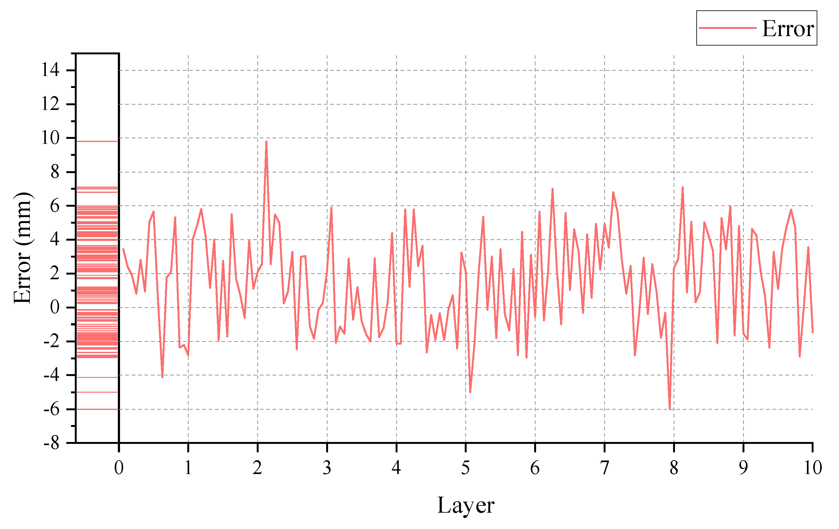
  • Comparative and real-world deployment experiments are conducted. The results show that MaskNet significantly outperforms YOLO11 in segmentation accuracy, and the integrated system achieves stable grasping performance with a maximum error of 9.85 mm and a 98% success rate in structured unloading tasks.
The remainder of this article is organized as follows: Section 2 describes the target objects and the hardware configuration of the depalletizing system. Section 3 details the design of MaskNet and presents comparative experiments. Section 4 reports the real-world depalletizing experiments, and Section 5 concludes the study.

2. System Construction

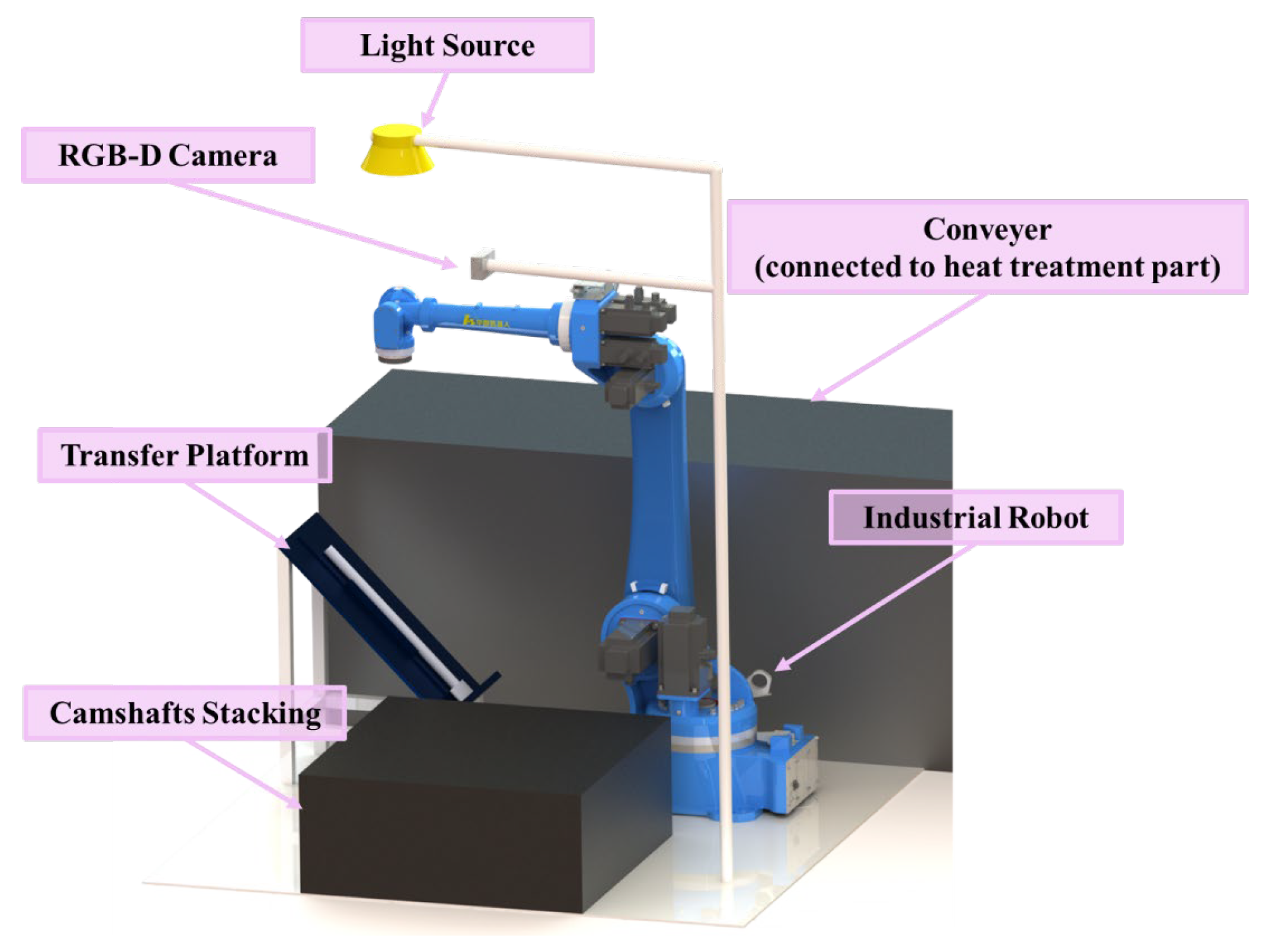
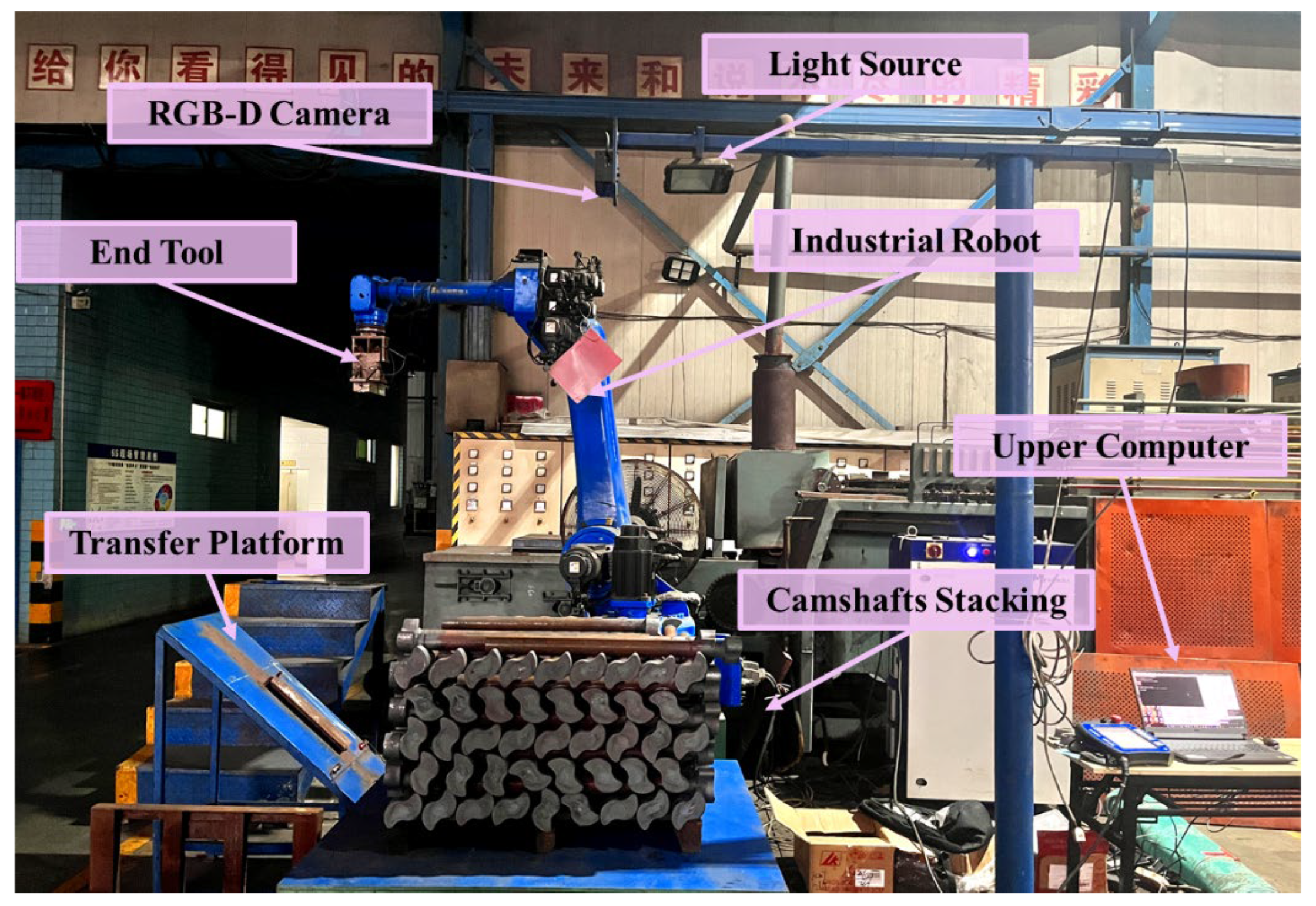
2.1. Palletizing Object and Hardware Overview

In this study, camshafts are stacked on wooden pallets in an interleaved pattern comprising 16 rows and 10 layers, as illustrated in Figure 1. The overall footprint of each stockpile measures 1200 mm × 1200 mm, and the camshafts exhibit dimensional variability in both length and cross-sectional diameter, as detailed in Table 1.
Although the main body of each camshaft is approximately cylindrical, the two ends differ markedly. The larger, T-shaped protrusion is hereafter referred to as the head, while the narrower spline end is referred to as the tail. When shafts are stacked head-to-tail, the head of one shaft often occludes the tail of its neighbor, producing fragmented and ambiguous visual cues. This overlap, rather than the cylindrical core, is the primary reason camshafts are treated as irregular objects in the present work. The dense stacking further increases the difficulty of accurate instance segmentation and grasp planning.
As presented in Figure 2, the hardware configuration consists of five primary components: a host computer, a six-axis industrial robot, an RGB-D camera, an end-effector, and a transfer platform (as summarized in Table 2). The host computer is a standard desktop workstation running a 64-bit Windows 10 operating system. To accommodate the required working range, an industrial robot with a 2100 mm reach and a maximum payload of 20 kg is selected. The RGB-D camera captures depth images at a resolution of 1280 × 960 pixels, with an effective working distance of 0.8 to 4.3 m. Its vertical accuracy is 0.56 mm at 900 mm and 3.14 mm at 2000 mm, while horizontal accuracy reaches 5.72 mm at 2500 mm.

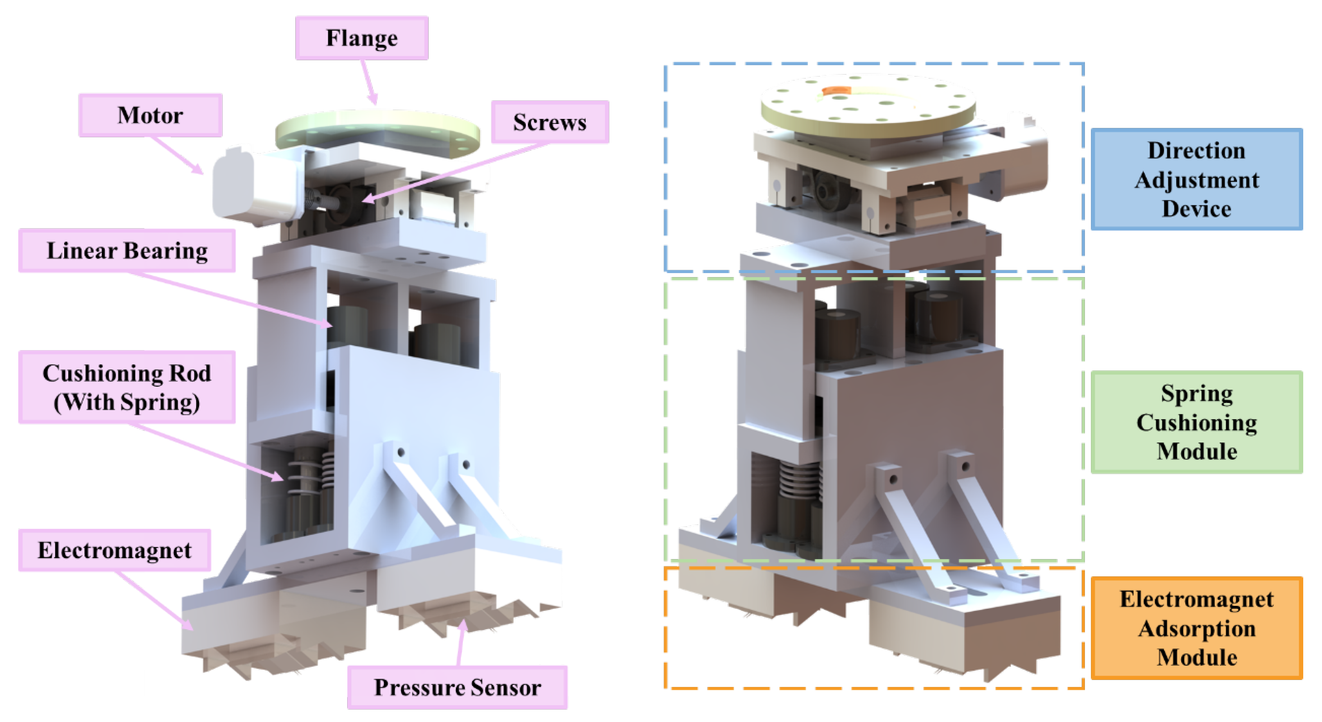
2.2. End Adsorption Device

A novel adsorption device is proposed for the successful adsorption of camshafts, comprising a direction adjustment module, a cushioning module, and an adsorption module. Given the uneven surface and significant mass of the camshafts to be grasped, a new electromagnetic adsorption mechanism is designed, which includes a V-shaped electromagnet and thin film force sensors. As the camshafts and the end of the adsorption device are metallic, a new cushioning mechanism is designed to mitigate the impact caused by adsorption. This mechanism involves four sets of rods with springs to provide a cushioning effect. Due to the cylindrical nature of the camshaft, it is prone to deviation when being grasped. To counter this, a direction adjustment device is designed.
The structure and functional partitioning of the end adsorption device are depicted in Figure 3. The magnetic end-effector is mechanically connected to the robot arm via a standard flange interface, which also integrates a buffering mechanism. The end-effector adopts a V-shaped electromagnetic chuck, powered by a 24 V DC supply, with a rated maximum suction force of 50 kg under ideal contact conditions. To reduce impact forces during vertical grasping motions, a custom-designed passive compliance module is installed between the robot flange and the electromagnet. This module consists of linear guide rails, spring-loaded shafts, and damping elements, providing an effective cushioning stroke of up to 80 mm. The compliant design mitigates rigid collision during camshaft extraction from tightly packed stacks and improves grasp reliability without requiring active force control. The direction adjustment apparatus, which includes a stepper motor, screws, and a stationary rack, detects variations in force via a thin-film pressure sensor affixed to the electromagnet. When a deviation occurs, the stepper motor of the device drives the screw to rotate, positioning the entire adsorption device in a more suitable adsorption posture.

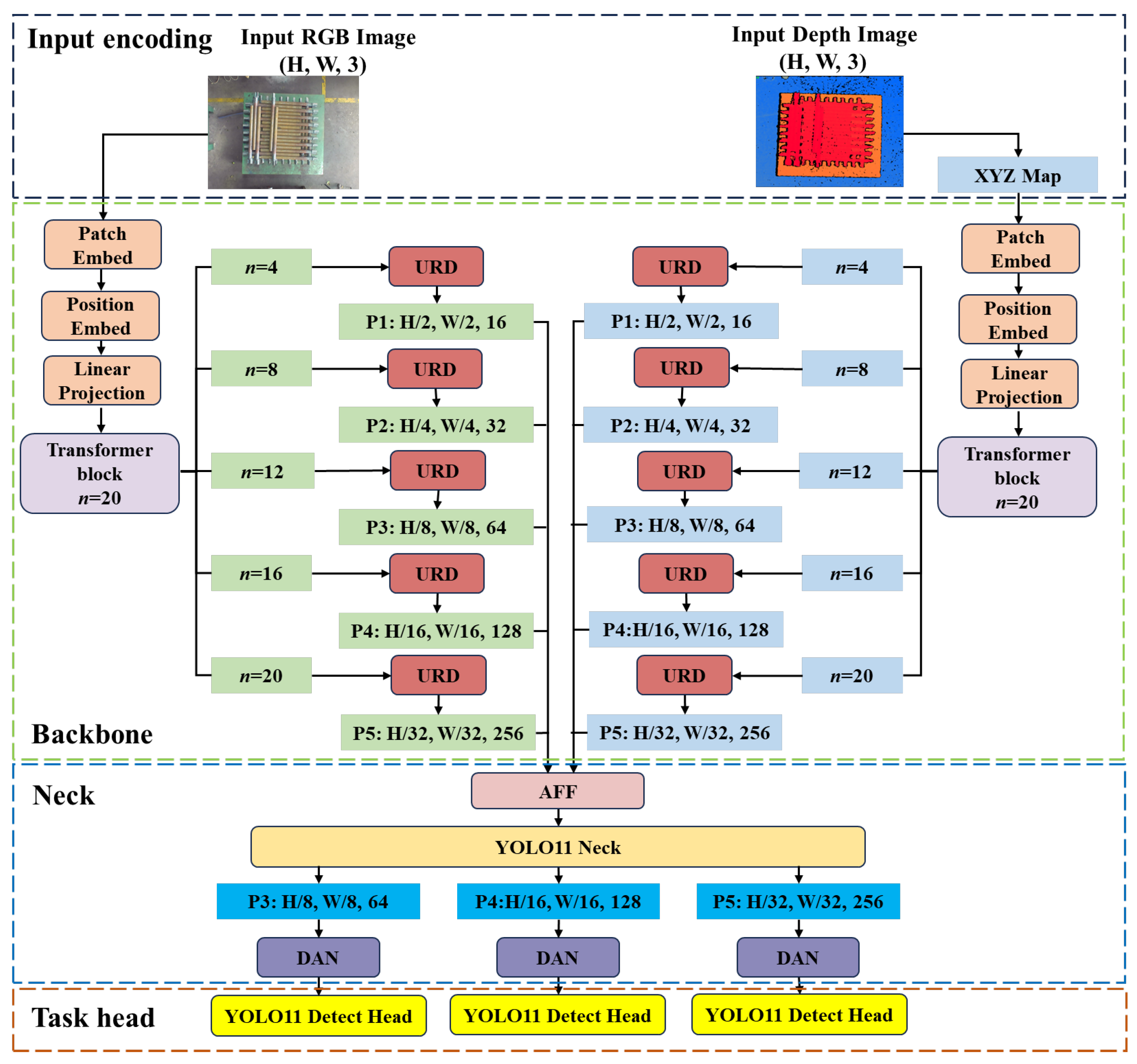
3. Transformer-Based RGB-D Instance Segmentation: The MaskNet Approach

3.1. Overall Architecture of the MaskNet

To address the challenges of segmenting camshafts that are densely stacked and interleaved—resulting in ambiguous boundaries and low visual separability—this study focuses on improving instance segmentation accuracy in complex industrial depalletizing tasks. Building upon the YOLO11 [30] framework, a ViT-enhanced instance segmentation network is designed, incorporating multi-modal feature fusion to improve segmentation robustness. The proposed method is referred to as MaskNet.
The overall architecture of the proposed MaskNet is illustrated in Figure 4. It consists of four main components: input encoding, backbone network, neck network, and task heads. Based on the YOLO11 framework, MaskNet introduces the following key improvements:
(1)
A depth modality is incorporated as an additional input. Specifically, the raw depth image is converted into an XYZ feature map through a tailored encoding strategy, providing rich spatial cues to complement the RGB data.
(2)
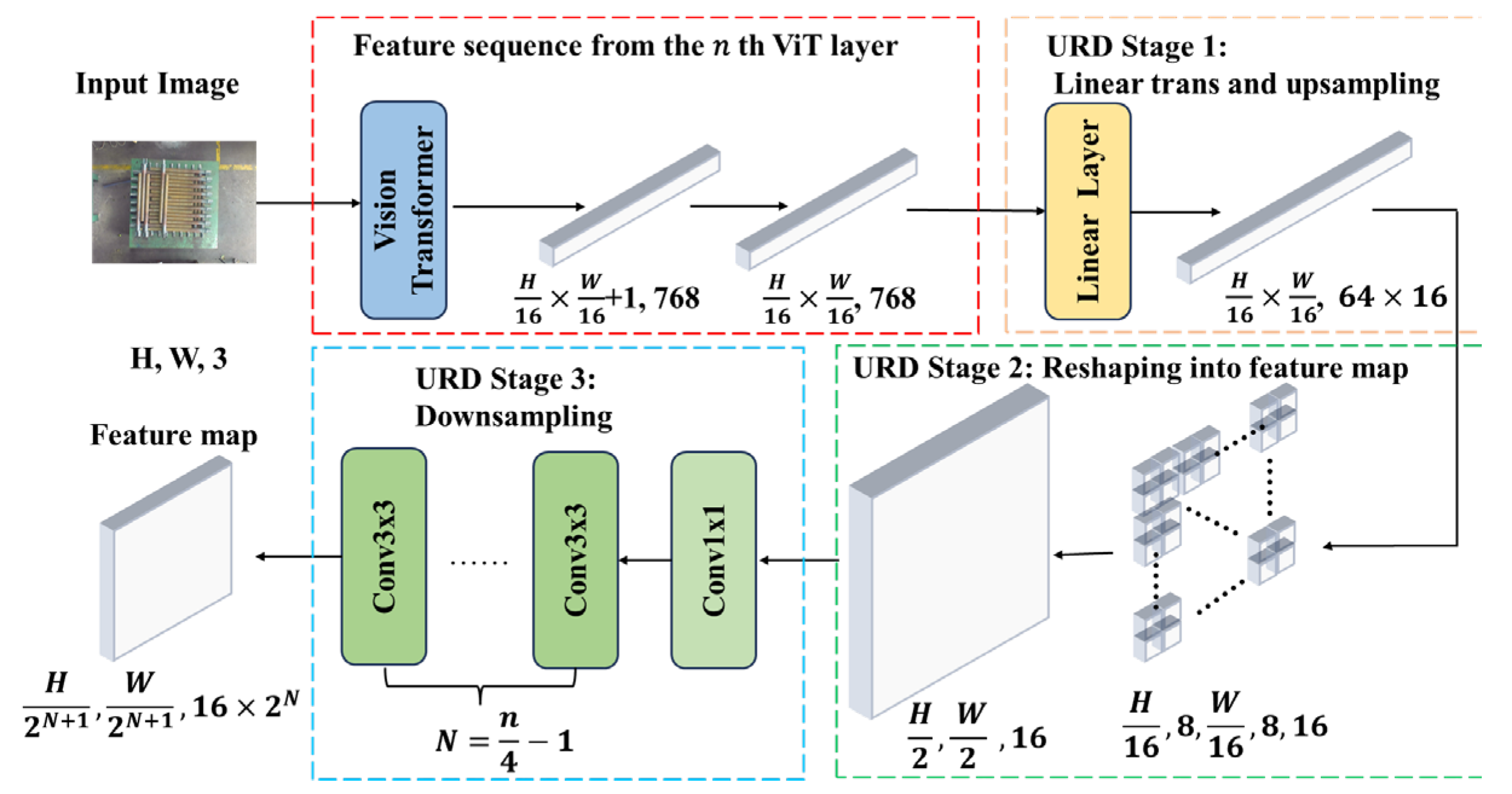
In the backbone, conventional bonvolution–BatchNorm–SiLU (CBS) and C3K2 modules are replaced by a Vision Transformer (ViT) with a depth of 20 layers. This substitution enables more efficient and expressive feature extraction while reducing architectural complexity. A dedicated Up-sample Reshape Down-sample (URD) module is introduced to reshape the ViT output vector into a feature map format, preparing it for subsequent multi-modal fusion.
(3)
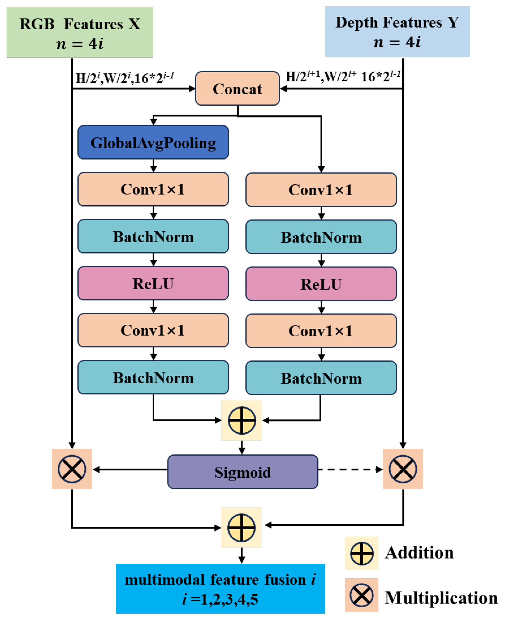
To facilitate multi-modal feature fusion, an attention-based Attentional Feature Fusion (AFF) module is appended to the end of the neck network. This module operates in conjunction with the original YOLO11 neck to construct a multi-modal, multi-scale feature pyramid.
(4)
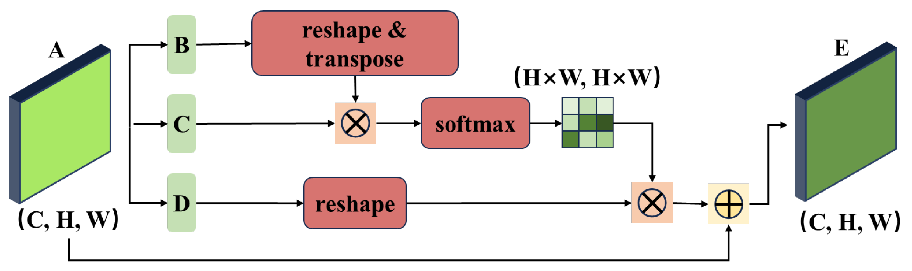
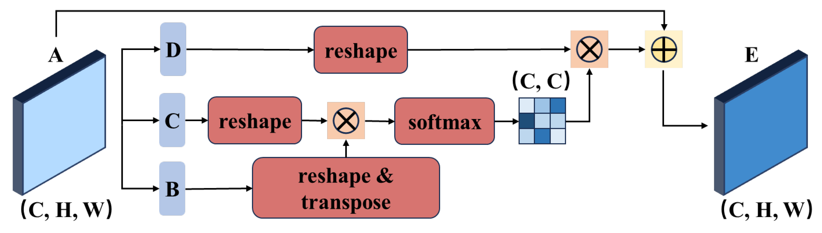
To further enhance mask segmentation accuracy, three lightweight Dual Attention Network (DAN) modules are integrated at the head stage. These modules capture dependencies along spatial and channel dimensions, strengthening feature expressiveness. Multi-scale feature maps are simultaneously fed into the YOLO11 detection head for bounding box and class prediction, and used to generate mask parameters that are combined to produce final instance masks.
In summary, MaskNet introduces comprehensive enhancements to YOLO11 in terms of backbone feature extraction, multi-modal and multi-scale fusion, and dual attention mechanisms. These improvements collectively enable more accurate and robust instance segmentation for unstructured grasping scenarios.
In RGB-D-based instance segmentation, it is common to extract features from RGB and depth images using two independent convolutional backbones. While 2D CNNs are typically applied to RGB images, point-based methods such as PointNet [31] or PointNet++ [32] are used for depth data. However, these approaches often yield limited improvements in segmentation accuracy. One major reason is that standard convolution operations—such as pooling, cropping, and RoI-Align—disrupt the spatial consistency of depth maps, thereby breaking the geometric correspondence between pixels and real-world 3D structure.
The projection of a 3D point (a, b, c) from object coordinates to image coordinates follows the perspective projection model, as described in Equation (1):
u v 1 = K R z ( a , b , c ) + T z R a b c + T
Here, R S O 3 and T R 3 represent the rotation and translation from the object to the camera coordinate system, and K is the camera intrinsic matrix. The term R z ( a , b , c ) + T z corresponds to the depth along the camera optical axis. This equation shows that each depth pixel (u, v, d) maps to a unique 3D point (x, y, z), tightly coupling spatial coordinates with image geometry.
However, in conventional CNN-based frameworks, geometric consistency is often lost due to spatial transformations that alter the pixel layout. This disrupts the projection model and leads to what we refer to as projection degradation, where the network loses the ability to maintain accurate 3D relationships in the feature space. The schematic diagram is presented in Figure 5.
To address this issue, MaskNet adopts a dual-branch Vision Transformer (ViT) architecture, where the RGB and depth modalities are processed separately but fused at the feature level. The depth map is converted into a three-channel XYZ feature representation by back-projecting each pixel using the intrinsic matrix K:
x y z = d K 1 u v 1
Here, x and y denote the spatial coordinates in the camera frame, and z represents the depth. These feature maps retain the original image resolution and preserve the geometry of the scene. The XYZ features are then concatenated along the channel dimension to form a structured depth representation that aligns with the RGB input in both shape and spatial semantics. By leveraging the ViT self-attention mechanism, MaskNet maintains the global contextual relationships across image patches, effectively mitigating projection degradation and enhancing segmentation performance in cluttered and geometrically complex scenes.
Although Equation (1) defines the full perspective projection using both intrinsic and extrinsic parameters, we construct the XYZ feature maps solely based on the intrinsic matrix K, as shown in Equation (2). We adopt this approach for two key reasons. First, the network is trained and evaluated using data from a fixed-view RGB-D sensor in a calibrated setup, ensuring geometric consistency across samples. Second, camera-frame XYZ encoding preserves spatial alignment with the RGB input and improves depth feature expressiveness compared to raw depth or sparse point clouds.

3.2. Vision Transformer-Based Feature Extraction

In MaskNet, RGB and depth features are extracted independently through two separate branches, each based on a Vision Transformer (ViT) architecture. A depth sweep experiment was conducted with ViT encoders of 10, 14, 20, and 24 layers. The results show that accuracy improvements become marginal beyond 20 layers, with mAP@0.5 increasing by less than 0.2 compared to the 24-layer variant. The backbone adopts ViT-20, which includes 20 consecutive transformer encoder layers, with a patch size of 16 and an embedding dimension of 768.
Taking the RGB modality as an example, an input image of size (H, W, 3) is divided into non-overlapping 16 × 16 patches, resulting in H 16 × W 16 patches. Each patch is flattened into a vector of length 768, forming a sequence of shape ( H 16 × W 16 , 768). A learnable linear projection is then applied (preserving the embedding dimension), followed by the addition of a classification token and positional encoding. This sequence is passed through the transformer encoder, where the output maintains a shape of ( H 16 × W 16 + 1768). Feature sequences from layers 4, 8, 12, 16, and 20 are selected as intermediate representations for constructing the feature pyramid.
To restore these sequences to feature maps at different resolutions, a dedicated URD (Up-sample, Reshape, Down-sample) module is introduced. As shown in Figure 6, the URD module first removes the class token, then applies a linear transformation to expand the channel dimension to 1024. The sequence is reshaped into a feature map of size ( H 2 , W 2 , 16 ) using slicing operations. This is followed by a 1 × 1 convolution and a series of 3 × 3 convolutions (with the number of layers dependent on the ViT stage), progressively reducing the spatial resolution while increasing the channel depth to form a hierarchical feature pyramid.

3.3. Attention-Based Multi-Modal Feature Fusion

In our feature extraction pipeline, RGB features primarily capture the color, texture, and surface details of objects, providing rich appearance information. In contrast, depth features reflect the geometric structure, spatial layout, and shape of the scene, offering stable cues under challenging conditions such as poor lighting or texture ambiguity. To effectively integrate the complementary strengths of these two modalities, we designed an Attention-Based Multi-modal Feature Fusion (AFF) module that fuses RGB and depth feature pyramids into a unified representation. This joint feature hierarchy incorporates both appearance and geometric information, enhancing robustness in complex environments. The structure of this module is presented in Figure 7.
Unlike simple fusion methods such as concatenation or element-wise addition, AFF introduces pixel-wise attention weights to adaptively regulate the contribution of each modality at every spatial location. In regions where RGB and depth signals diverge or conflict, the attention mechanism enables the network to automatically prioritize the more reliable modality, thereby suppressing noise and reducing the impact of uncertain features.
Structurally, AFF consists of three stages. First, RGB and depth features are concatenated along the channel dimension to form a bimodal tensor. This combined feature map is then processed in parallel through a local attention branch, which captures fine-grained spatial differences between modalities, and a global attention branch, which extracts scene-level semantic statistics via global average pooling followed by a series of 1 × 1 convolutions, batch normalization, and Rectified Linear Unit (ReLU) activation. The outputs of both attention branches are summed and passed through a sigmoid activation to generate a pixel-wise fusion weight map. This map is used to perform weighted blending of RGB and depth features, enabling the network to adaptively adjust modality contributions at each pixel location. Through this mechanism, AFF significantly improves the discriminability and stability of the fused features, especially in visually ambiguous or sensor-degraded scenarios.

3.4. Spatial and Channel Feature Fusion with Attention Mechanism

To enhance feature representation across modalities, an Attention-Based Feature Fusion (AFF) module is introduced to integrate RGB and depth feature pyramids. Instead of simple concatenation, AFF adaptively learns pixel-wise weights to determine how much information to extract from each modality. It combines local and global attention to capture both spatial details and overall semantic context, generating a dynamic fusion map. This allows the network to emphasize more reliable features and suppress noise, improving segmentation performance in complex scenes.
After multi-modal feature fusion, the resulting feature maps are fed into the neck of the original YOLO11 framework. The neck builds a top-down feature pyramid, progressively upsampling high-level semantic features and merging them with low-level features to enhance spatial detail while preserving semantic information. The final output consists of multi-scale fused feature maps at three resolutions, capturing both coarse and fine-grained object representations.
In neural networks, feature maps contain both spatial (H × W) and channel (C) dimensions. Spatial features correspond to local structures like edges and textures, while channel features represent different types of extracted semantics. In unstructured grasping scenarios with dense object stacking, feature distributions become complex. Simply passing these feature maps to detection heads, as in the original YOLO11, treats all spatial locations and channels equally, limiting the model’s ability to focus on task-relevant patterns.
To address this, we introduce a lightweight attention module called DAN at the head of the neck network. DAN independently computes channel and spatial attention, then combines them to generate refined attention weights. This dual attention mechanism enables the network to emphasize discriminative channels and spatial regions, enhancing segmentation performance in cluttered scenes. The structure of spatial DAN is presented in Figure 8.
The original feature map A is first processed through batch normalization and ReLU activation to produce three identical feature maps: B, C, and D. Feature maps B and C are then reshaped along the spatial dimension, with C transposed, resulting in matrices of shape R ( H × W ) × C and R C × ( H × W ) , respectively. Matrix multiplication between them yields a similarity matrix representing spatial correlations across all positions. After applying Softmax normalization, a spatial attention map S R ( H × W ) × ( H × W ) is obtained. This attention map is multiplied by the reshaped feature D and then restored to its original spatial shape. Finally, a learnable coefficient α (initialized as zero) is used to weight the result, which is then added element-wise to the original feature map A to obtain the final output. The final output of the spatial attention module is computed as follows:
E j = α i = 1 N   s i j D i + A j , N = H × W
As shown in Figure 9, channel attention is designed to preserve the original channel-wise feature representation without generating new feature maps through convolution. The operation is conceptually similar to spatial attention, but spatial information is excluded from the computation. Specifically, the feature map B is first transposed to obtain a matrix of shape R C × ( H × W ) , which is then multiplied with the original (non-transposed) feature map C. After applying Softmax normalization, a channel attention map S R C × C is obtained, representing the inter-channel relationships.
Finally, the refined feature output is computed using a learnable scalar coefficient β, as defined in Equation (4):
E j = β i = 1 N   s i j D i + A j , N = C
The DAN module integrates the outputs of the spatial and channel attention branches through a convolutional layer followed by element-wise summation, enabling efficient feature fusion. Owing to its lightweight structure and minimal parameter overhead, the attention mechanism significantly enhances feature representation and is well-suited for complex scenarios.

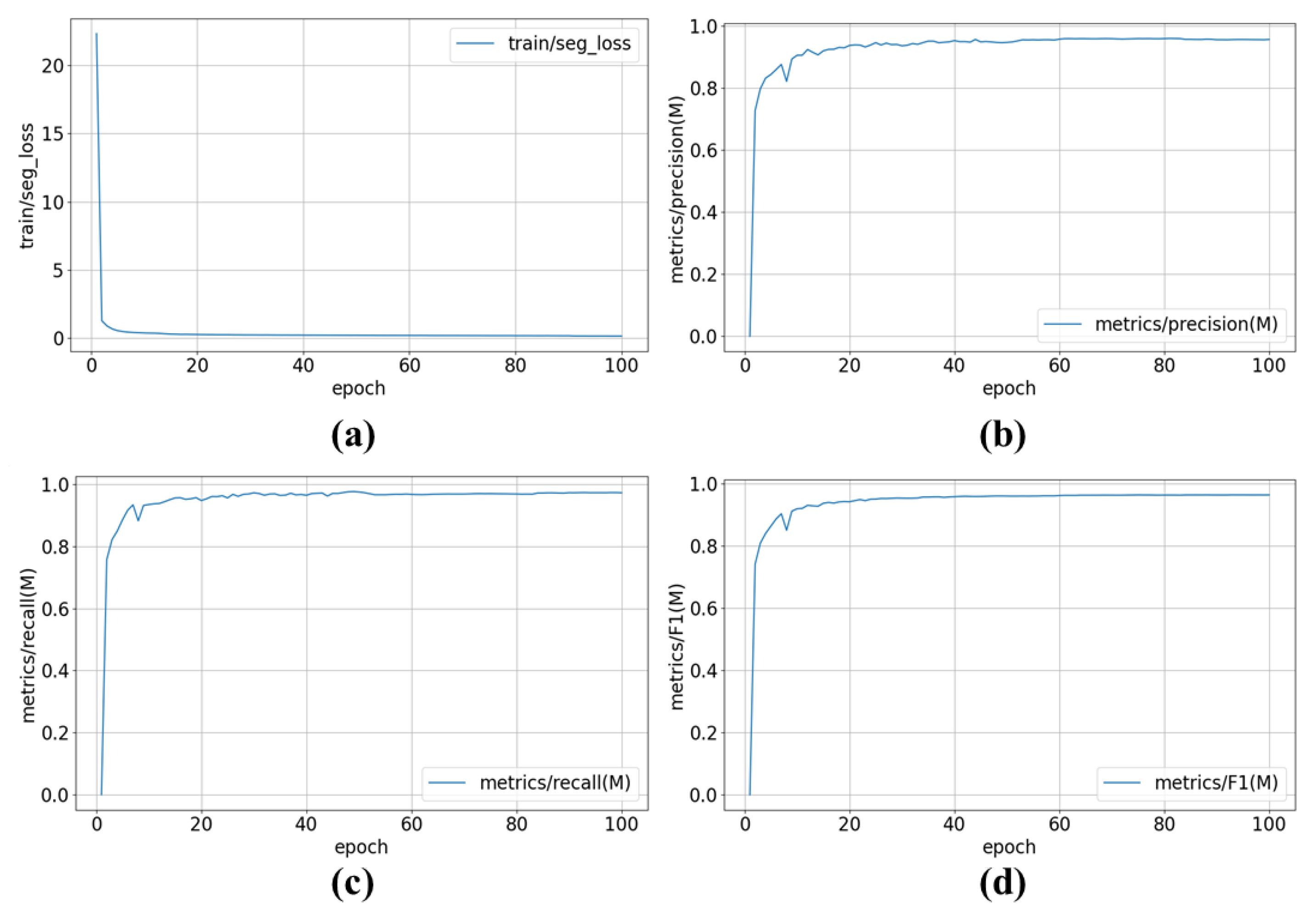
3.5. Network Performance Evaluation

3.5.1. Comparison Experiment

All experiments were conducted using PyTorch 2.4.0 as the deep learning framework, with CUDA version 12.4 and Python 3.10, running on Ubuntu 22.04. The hardware platform featured an NVIDIA GeForce RTX 4090 GPU (Nvidia, Santa Clara, CA, USA) with 24 GB of VRAM.
To evaluate the performance of the instance segmentation algorithm, three standard metrics were adopted: precision, recall, and F1-score. The dataset was split in a ratio of 8:1:1 into training, validation, and test sets, comprising 8000, 1000, and 1000 images, respectively. All images were resized to 960 × 960 pixels and preprocessed before being fed into the network for training.
The ViT backbone in MaskNet was initialized with ImageNet-21k pretrained weights to facilitate convergence, given the relatively limited dataset size. The model was optimized using Stochastic Gradient Descent (SGD) with a momentum of 0.937 and a weight decay of 0.0005. Training was carried out for 100 epochs with a batch size of 12. The initial learning rate was set to 0.01 and gradually decayed to 0.0001 over the course of training. The random seed is set to 0. During each epoch, the entire training set was traversed, and model weights were updated based on the computed gradients from the loss function.
During training, we applied three lightweight data-augmentation operations online to every aligned RGB–depth pair. First, a random horizontal flip (probability 0.5) broadens viewpoint diversity without breaking geometric consistency. Second, colour jittering with ±15% changes in brightness, contrast, and saturation simulates the moderate lighting variations typical of the shop floor and reduces the risk of over-fitting to a single illumination profile. Third, additive Gaussian noise in the depth channel (σ = 0.01 m) mimics range-sensor quantisation error and helps the model stay tolerant to small height inaccuracies.
To further illustrate the training dynamics, Figure 10 presents the evolution of segmentation loss, precision, recall, and F1-score over 100 epochs. These curves demonstrate that the model converges steadily, with all metrics stabilizing after approximately 30 epochs, and no evidence of overfitting or underfitting was observed throughout the training process.
(1)
Precision Comparison
MaskNet achieves a maximum precision of 0.98, outperforming YOLO11, which reaches 0.94 under the same evaluation settings. In addition to higher peak performance, MaskNet maintains consistently high precision across all object categories, even at lower confidence thresholds. To further evaluate overall localization quality under stricter conditions, we also computed the COCO-style mAP@0.5:0.95. MaskNet achieves 0.723, while YOLO11 yields only 0.592 under the same input resolution and evaluation protocol. This gap reflects improved ability of MaskNet to generate well-aligned segmentation masks across a range of IoU thresholds, further validating its advantage in precision-sensitive industrial applications. The precision metric is defined as
P r e c i s i o n = True   Positives True   Positives + False   Positives
(2)
Recall Comparison
MaskNet achieves 100% recall at a confidence threshold of 0.0, meaning it successfully detects all target objects without omission. As the threshold increases, recall remains stable across a wide range and only begins to decline near 0.8–0.9, reflecting strong and reliable detection performance. In contrast, YOLO11 reaches only 95% recall at a threshold of 0.0, and recall for several categories drops significantly as the threshold increases, indicating instability and limited sensitivity in more challenging detection cases. The recall metric is defined as
R e c a l l = True   Positives True   Positives + False   Negatives
(3)
F1-Score Comparison
MaskNet achieves a maximum average F1-score of 0.96 at an optimal threshold of 0.54, significantly outperforming YOLO11, which peaks at 0.86 with a lower threshold of 0.356. Moreover, MaskNet maintains a stable balance between precision and recall within a wide confidence range (0.2–0.8), while YOLO11 displays more dispersed and inconsistent F1-score behavior across categories.
(4)
Horizontal Comparison with State-of-the-Art Methods
To further contextualize the performance of MaskNet, a comparison was conducted against two recent instance segmentation models: Mask2Former-S and SAM-B. These models represent state-of-the-art approaches based on hierarchical transformer architectures and prompt-driven segmentation, respectively.
All models were trained on the RTX 4090 to reduce development time. However, to ensure fair and practical comparison, all inference results in the horizontal comparison were obtained on a standard industrial PC equipped with an NVIDIA RTX 3060 GPU, which reflects the actual deployment environment.
Table 3 presents the performance comparison across six key dimensions: segmentation accuracy, F1-score, inference speed, deployment difficulty, and suitability for real-time robotic applications.
While Mask2Former and SAM report marginally higher mAP values, their substantial computational complexity and lower inference speed limit their applicability in time-sensitive industrial scenarios. Considering the real-time constraints of robotic depalletizing systems, a segmentation method that offers a favorable trade-off between accuracy and efficiency is more appropriate for practical deployment. MaskNet fulfills this requirement by achieving competitive precision with significantly lower latency and resource demands.
Real-Time Suitable simply indicates whether the model can achieve the required inference speed on our standard industrial PC. In contrast, deployment difficulty reflects the practical effort needed to install and run the model in a production setting, covering factors such as model size, memory footprint, and software dependencies. A method may be fast enough to meet real-time demands yet still require specialized hardware or complex setup, resulting in higher deployment difficulty. Conversely, models rated as low deployment difficulty can be easily integrated and executed with minimal configuration.

3.5.2. Ablation Study

To evaluate the contribution of each module to the overall performance of MaskNet, five ablation experiments were conducted. The experiments focused on the impact of three components: ViT-based feature extraction (with URD), attention-based multi-modal fusion, and spatial-channel attention enhancement via the DAN module. By comparing different combinations, the influence of each module on precision (P), recall (R), and F1-score can be clearly observed.
The ablation settings are defined as follows:
A.
Indicates whether ViT + URD is used for feature extraction; otherwise, the original YOLO11 backbone (CBS + C3K2 + SPPF + C2PSA) is used.
B.
Denotes the use of attention-based multi-modal fusion; B1 and B2 represent fusion via element-wise addition or feature map concatenation, respectively.
C.
Indicates whether the DAN module is used for spatial and channel attention enhancement.
Table 4 summarizes the experimental results under different settings. Under a confidence threshold of 0.5 (P as mAP@0.5) and IoU of 0.6, the full MaskNet configuration achieves the highest performance: P = 0.980, R = 0.971, and F1 = 0.975.
Comparing Experiment 1 and Experiment 2 highlights the importance of ViT-based feature extraction. The CNN-based baseline suffers from projection distortion when handling depth input, which ViT effectively mitigates in early layers.
Comparing Experiments 1, 3, and 4 shows that attention-based fusion adaptively assigns weights across modalities and channels, improving discriminability. Simple fusion methods such as addition (B1) or concatenation (B2) fail to emphasize informative features, leading to lower precision and recall.
The comparison between Experiments 1 and 5 reveals that the DAN module enhances the ability of the model to focus on relevant spatial regions and suppress background noise. Removing DAN causes a slight drop in localization accuracy, though overall performance remains high due to the retained ViT and multi-modal fusion modules.
In summary, the improvements introduced in MaskNet across feature extraction, multi-modal fusion, and dual attention collectively deliver complementary and synergistic benefits, resulting in significantly enhanced segmentation performance under complex grasping scenarios.

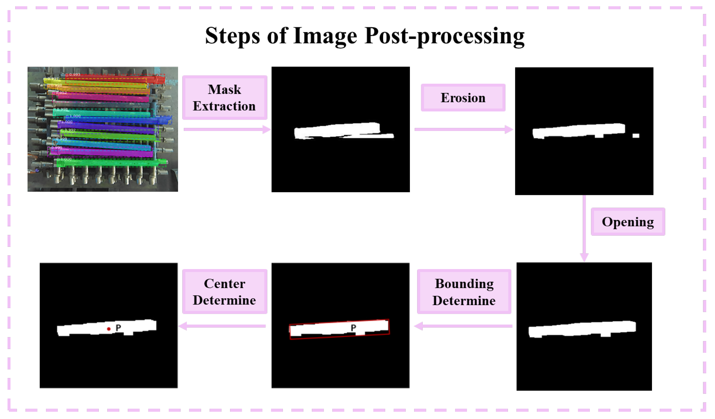
4. Depalletizing Strategy and Real-World Validation

4.1. Depalletizing Strategy

After segmenting the individual camshaft, there follows a series of image post-processing steps. Including erosion, opening, bounding determine, and center determine, as shown in Figure 11.
The process of determining the center of the camshaft involves two main steps. The first step is to calculate the rotation angle of the minimum bounding rectangle, which begins with the calculation of the covariance matrix C of the bounding box, where n is the number of points in the contour point set C, ( x i , y i ) is the coordinate of the i-th point in the contour point set, and ( x ¯ , y ¯ ) is the coordinate of the center point of the bounding box.
C = 1 n i = 1 n   ( x i x ¯ ) ( y i y ¯ )
Next, we perform an eigenvalue decomposition on the covariance matrix C, where V is the eigenvector matrix and D is the diagonal eigenvalue matrix. The eigenvalues of the covariance matrix C are then sorted in descending order, i.e., d1 > d2.
C = V D V T
The final step involves taking the eigenvector corresponding to the smallest eigenvalue as the rotation direction of the minimum bounding rectangle.
θ = a r c t a n v y 2 v x 2
where v x 2 and v y 2 are the elements corresponding to the second column of the eigenvector V . The second step in determining the center of the camshaft involves calculating the center point and dimensions of the bounding box. The center point P ( x , y ) of the bounding box is computed as follows:
P ( x , y ) = x m a x + x m i n 2 , y m a x + y m i n 2
where x m a x , x m i n , y m a x , and y m i n represent the maximum and minimum values of the x and y coordinates of all points in the contour point set C. While the depth features have already been mapped using Equation (2), the 3D grasping position is determined by the pixel coordinate P ( x , y ) together with its corresponding depth value at that location, as presented in Figure 12.

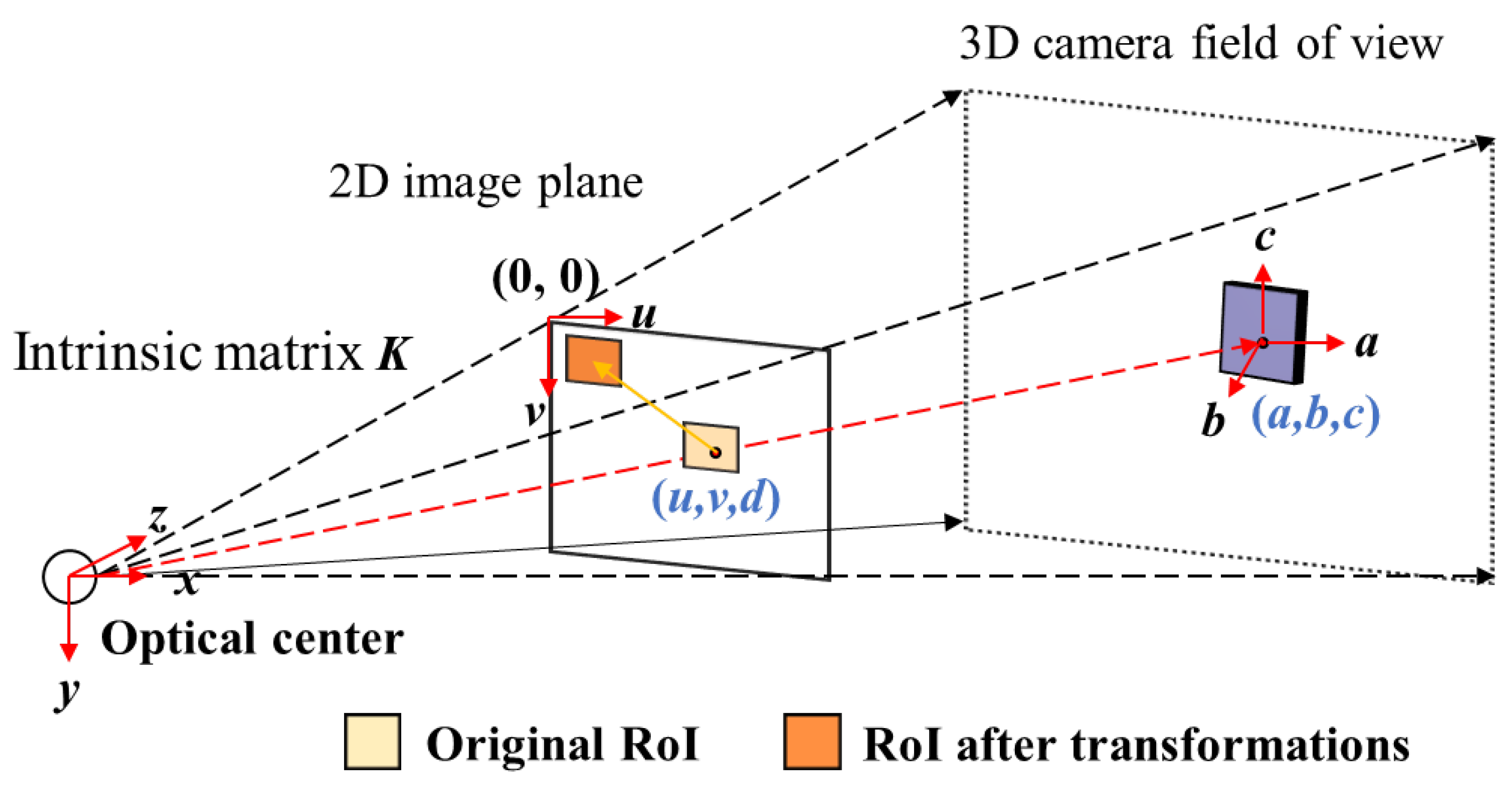
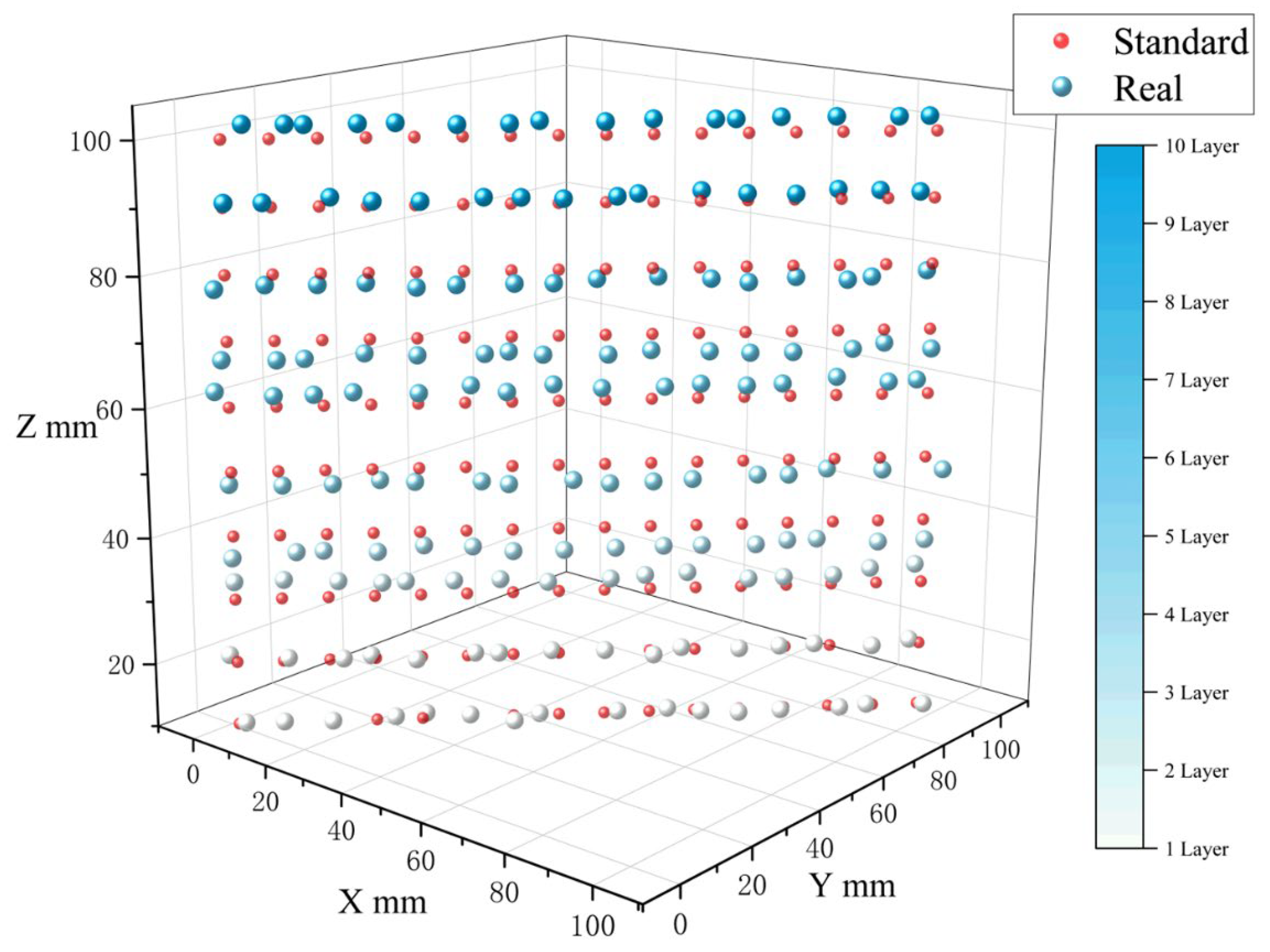
4.2. Hand–Eye Calibration

To accurately map 3D grasping positions from the camera frame ( X W , Y W , Z W ) to the robot frame ( X C , Y C , Z C ) , a rigid transformation matrix E t o R is estimated. This transformation consists of a rotation matrix R and a translation vector T, forming a 4 × 4 homogeneous matrix as shown in Equation (11):
E t o R = R T 0 1
Using this matrix, any point in the camera coordinate system can be transformed into the robot coordinate system as follows:
X C Y C Z C 1 = E t o R X W Y W Z W 1
To estimate the parameters of E t o R , at least four sets of corresponding 3D points in both the camera and robot coordinate systems are required. In this study, six sets were used to reduce random errors and improve numerical stability.
The transformation parameters are solved using the pseudo-inverse method to minimize the least-squares error. For example, the translation row parameters are obtained by
r 11 r 12 r 13 t 1 = P T 1 X C 1 X C 2 X C n
When the matrix P is full-rank, its pseudo-inverse is computed as
p i n v ( P ) = P T ( P T P ) 1
This calibration ensures accurate alignment between the visual perception system and robotic execution, enabling reliable grasping in the real-world coordinate space.

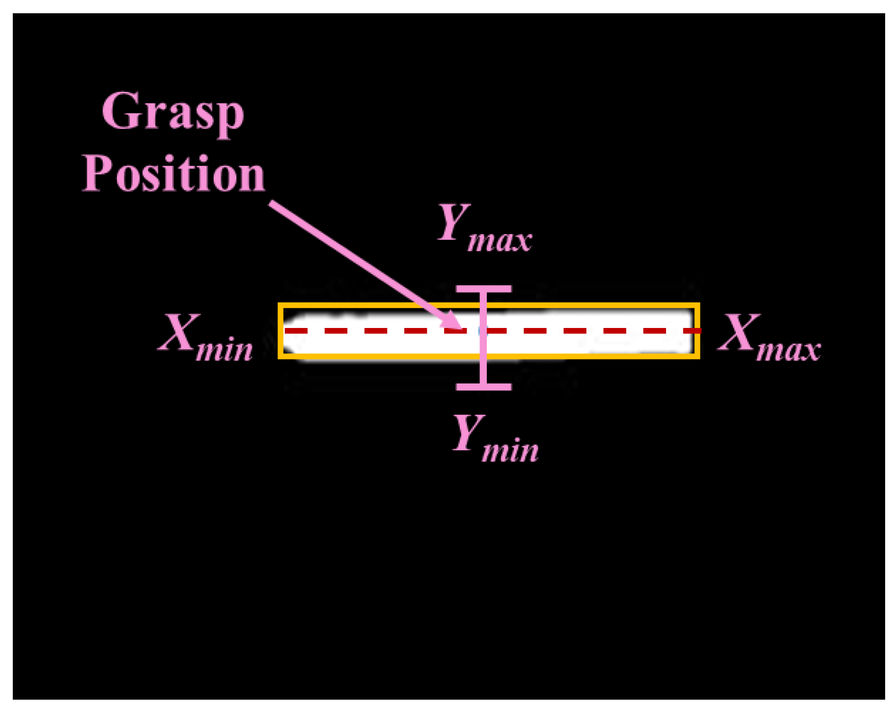
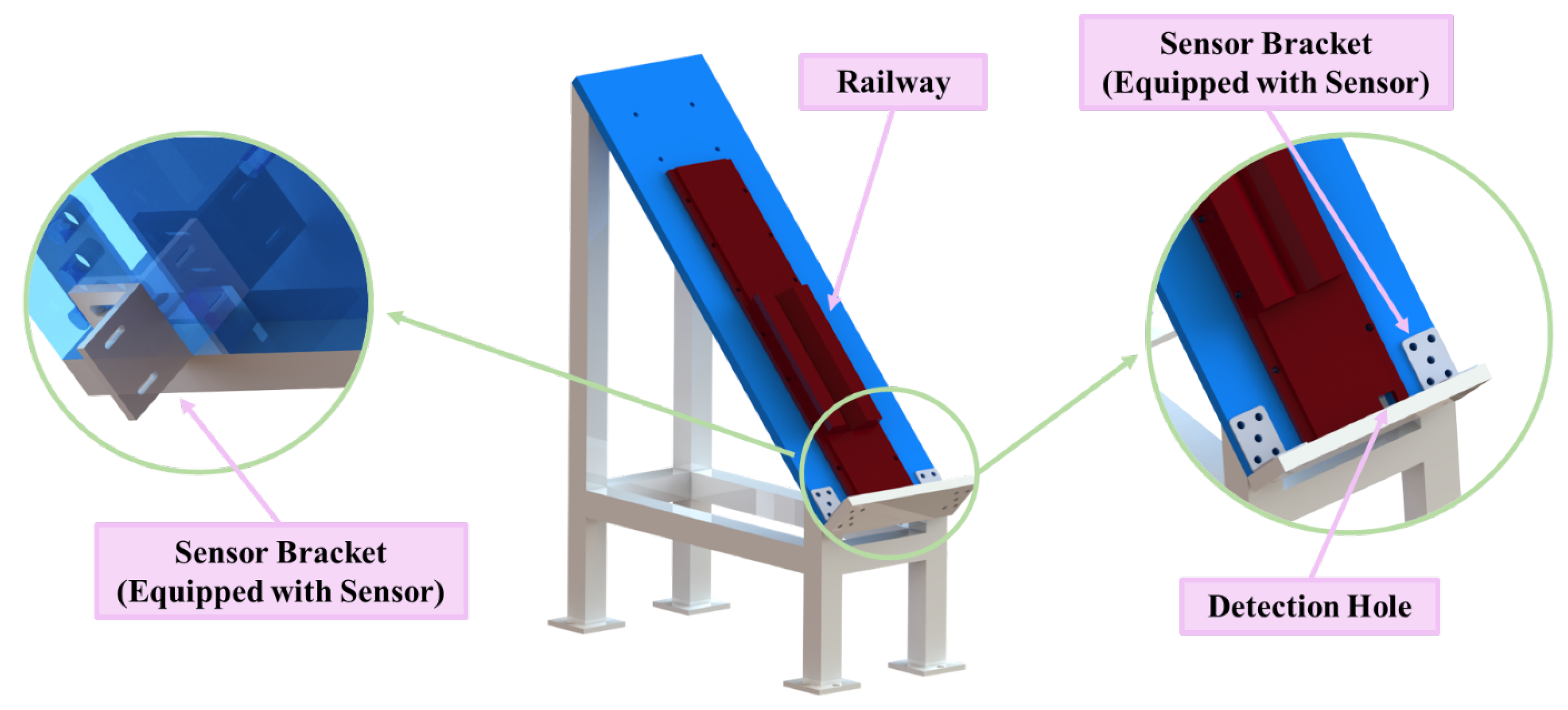
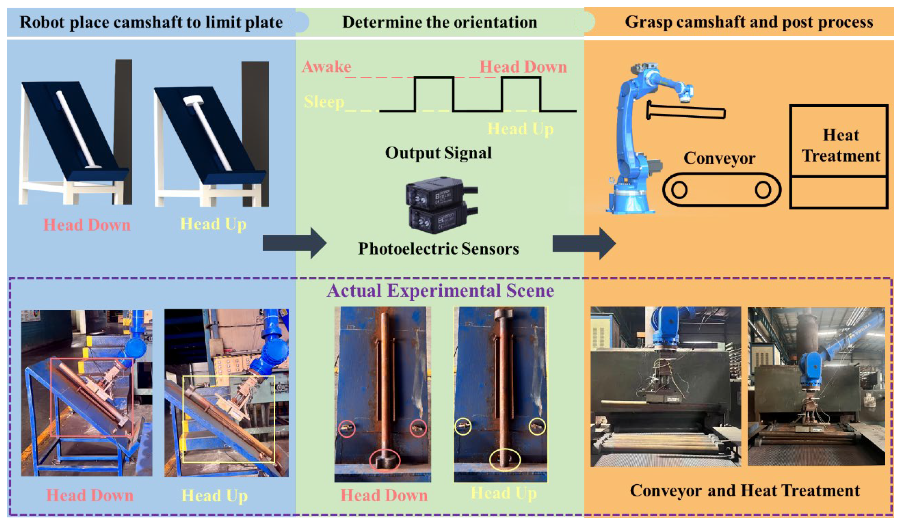
4.3. Transfer Platform for Center Point Positioning and Orientation Judgment

In the depalletizing workflow, the robot begins by placing a camshaft onto the designated transfer platform. The camshaft then slides downward along the track until it contacts a limit plate. A set of paired photoelectric switches is installed beneath the platform. These switches are activated as the camshaft moves along the track, generating an output signal. When the robot re-adsorbs the camshaft, the departure is detected by the sensors, and the output signal is reset, serving as feedback to confirm a successful grasp.
As shown in Figure 13, a photoelectric switch is embedded within a detection hole at the bottom of the platform to determine the camshaft’s orientation. If the camshaft’s head is positioned downward, it blocks the sensor, activating both the sensor output and the robot’s input signal. If the sensor remains unobstructed, the orientation is recognized as tail-end down.
As illustrated in Figure 14, the presence of limit plates enables the determination of the camshaft center position based on its length when it settles into place. This position is used to guide the robot during re-adsorption. The transfer platform thus performs two key functions: identifying the camshaft orientation and locating the center for precise re-adsorption.

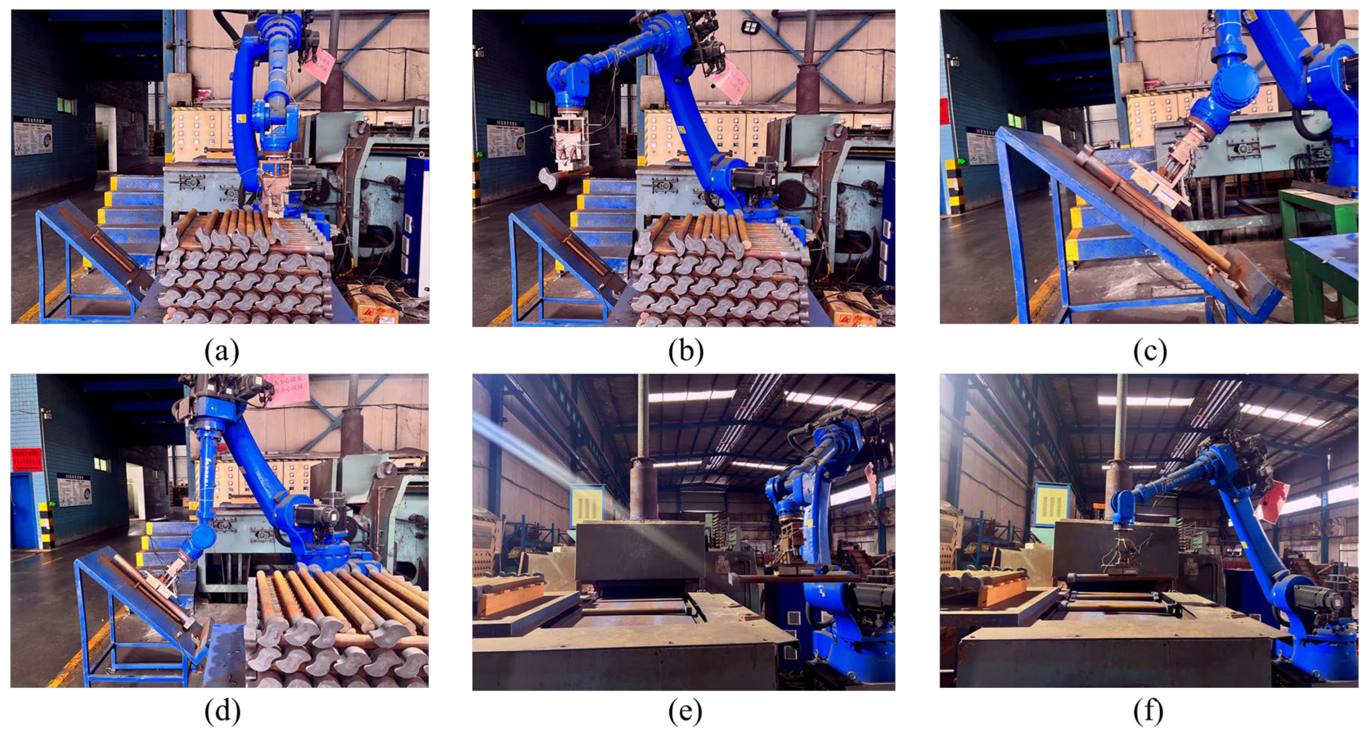
4.4. Depalletizing Experiments

The hardware implementation of the intelligent depalletizing system in an actual factory setting is presented in Figure 15.
The system is designed to achieve alternating placement of camshafts onto the conveyor belt. The overall workflow is illustrated in Figure 16. First, the RGB-D camera captures an image of the stacked camshafts. The image is processed using the proposed instance segmentation algorithm MaskNet, which extracts the object masks and identifies candidate grasping points. The pixel coordinates are then converted into robot coordinates through hand–eye calibration, and the robot is guided to execute the grasping motion (Figure 16a). Next, the camshaft is transferred to the platform where its orientation is detected using a photoelectric sensor embedded in a detection hole (Figure 16b). Once the orientation is determined, the center position of the camshaft is located and grasped for re-adsorption (Figure 16c,d). The robot then moves the camshaft above the conveyor belt, where the final placement orientation is computed based on both the current orientation determined by the platform and the previous camshaft’s orientation (Figure 16e). This ensures a consistent alternating head-to-tail arrangement, as shown in Figure 16f.
This article employs hand–eye calibration to convert image coordinates into robot coordinates. The experiment is grounded in the experimental analysis of hand–eye calibration errors. To clearly demonstrate the results of the calibration experiment, a camshaft with 16 axes and 10 layers is utilized. This setup allows for a comprehensive evaluation of the calibration process. The discrepancy between the hand–eye calibration coordinates of the camshaft profile (standard point) and the real adsorption center point of the robot is deemed to be the error. The hand–eye calibration coordinates obtained in the experiment and the actual adsorption point of the robot are depicted in Figure 17.
Upon completion of calibration, the total error is measured as the Euclidean distance between these points. To visualize the distribution of this error, a rug plot is used, as shown in Figure 18.
In practice, when the error exceeds 10 mm, grasping fails due to insufficient magnetic force. However, in the conducted experiments, the maximum error was 9.85 mm, with an average deviation of 5.61 mm and a standard deviation of 2.91 mm. These results demonstrate that the system meets the precision requirements for camshaft handling. No missed or repeated detections were observed, and the robotic system consistently achieved reliable placement.
Overall, the experimental findings validate the effectiveness of the proposed hand–eye calibration strategy in ensuring accurate and robust performance within the automated depalletizing framework.
This study selected three different lengths of camshafts for the unstacking experiment testing. Each specification was placed on 10 layers, with a total of 160 pieces as a stockpile. Each specification was tested for 10 consecutive stockpiles, with a success rate of 100%. In addition, the efficiency of the intelligent palletizing system designed in this article was compared with that of manual handling of camshafts. The handling efficiency of this system was at least 18% higher than that of manual handling, as shown in Table 5.
If a grasp attempt fails, the system automatically reinitiates the recognition and planning process. After five consecutive failures at the same location, it halts the operation and issues a prompt for system recalibration or manual intervention.
Two primary failure modes were identified. The first arises from height estimation inaccuracies in the depth sensor, which leads to deviations in the planned grasp position. These spatial errors weaken magnetic adhesion and may result in unstable or failed grasps. The second is more prevalent for longer camshafts, such as the 800 mm variant, where failures typically occur during vertical extraction from densely stacked bins. In these cases, the camshaft may inadvertently contact adjacent parts during lifting, especially when the initial pose is slightly tilted, leading to misalignment or accidental drops.
Additionally, the FM811 depth camera introduces measurable sensing noise. As shown in Table 2, the Z-axis error reaches up to 8.23 mm at a 2000 mm distance. Although the camera was positioned at 800 mm during deployment, where vertical error reduces to 3.29 mm, this residual uncertainty still contributes to occasional grasping deviations.

5. Conclusions

This study proposes a vision-guided robotic depalletizing system tailored for complex industrial environments involving densely stacked and irregular camshafts. The system integrates a flexible magnetic adsorption device, an RGB-D depth camera, and a six-axis robot, along with a dedicated transfer platform for orientation sensing. To address challenges such as object occlusion, interleaved placement, and segmentation ambiguity, we introduce MaskNet, a novel instance segmentation network that employs dual Vision Transformer encoders and attention-based feature fusion to achieve robust and precise object recognition in cluttered scenes. It achieves 0.980 precision, 0.971 recall, and 0.975 F1-score, significantly outperforming the YOLO11 baseline (0.949/0.936/0.942), particularly under dense stacking scenarios.
To ensure accurate execution in the real world, a complete hand–eye calibration procedure is implemented for aligning camera and robot coordinate systems, and a grasping strategy based on orientation feedback is designed to enable alternating placement. Extensive deployment experiments confirm the system’s reliability, with a maximum grasping error of 9.85 mm and a 98% success rate in multi-layer structured unloading tasks.
The key contributions of this study are as follows:
  • A complete RGB-D-based robotic depalletizing system is developed for irregular camshaft handling, featuring flexible magnetic adsorption and real-time orientation sensing.
  • A novel instance segmentation framework, MaskNet, is proposed, which fuses RGB and depth modalities through dual-branch Vision Transformers and attention-based mechanisms, achieving high segmentation accuracy under occlusion and dense stacking.
  • Real-world experiments validate the practical effectiveness of the system. The integration of hand–eye calibration and a structured grasping strategy enables accurate re-adsorption and alternating placement, achieving robust performance in complex industrial scenarios.

Author Contributions

Conceptualization, R.W. and P.Y.; methodology, R.W.; software, R.W.; validation, R.W. and P.Y.; formal analysis, R.W. and P.Y.; investigation, R.W. and P.Y.; resources, R.W. and P.Y.; data curation, R.W. and P.Y.; writing—original draft preparation, R.W.; writing—review and editing, R.W. and P.Y.; visualization, R.W.; supervision, P.Y.; project administration, P.Y.; funding acquisition, P.Y. All authors have read and agreed to the published version of the manuscript.

Funding

This research was funded by the National Natural Science Foundation of China, grant number No. 51975497.

Data Availability Statement

The data presented in this study are available on request from the corresponding author. The data are not publicly available due to industrial confidentiality and non-disclosure agreements with our collaborators.

Conflicts of Interest

The authors declare no conflicts of interest.

References

  1. Stibinger, P.; Broughton, G.; Majer, F.; Rozsypalek, Z.; Wang, A.; Jindal, K.; Zhou, A.; Thakur, D.; Loianno, G.; Krajnik, T.; et al. Mobile Manipulator for Autonomous Localization, Grasping and Precise Placement of Construction Material in a Semi-Structured Environment. IEEE Robot. Autom. Lett. 2021, 6, 2595–2602. [Google Scholar] [CrossRef]
  2. Baldassarri, A.; Innero, G.; Di Leva, R.; Palli, G.; Carricato, M. Development of a Mobile Robotized System for Palletizing Applications. In Proceedings of the 25th IEEE International Conference on Emerging Technologies and Factory Automation (ETFA), Vienna, Austria, 8–11 September 2020. [Google Scholar]
  3. Katsoulas, D.; Kosmopoulos, D.I. An Efficient Depalletizing System Based on 2D Range Imagery. In Proceedings of the IEEE International Conference on Robotics and Automation, Seoul, Republic of Korea, 21–26 May 2001; Volume 1, pp. 305–312. [Google Scholar]
  4. Nakamoto, H.; Eto, H.; Sonoura, T.; Tanaka, J.; Ogawa, A. High-Speed and Compact Depalletizing Robot Capable of Handling Packages Stacked Complicatedly. In Proceedings of the IEEE/RSJ International Conference on Intelligent Robots and Systems, Daejeon, Republic of Korea, 9–14 October 2016; pp. 344–349. [Google Scholar]
  5. Tanaka, J.; Ogawa, A.; Nakamoto, H.; Sonoura, T.; Eto, H. Suction Pad Unit Using a Bellows Pneumatic Actuator as a Support Mechanism for an End Effector of Depalletizing Robots. Robomech J. 2020, 7, 2. [Google Scholar] [CrossRef]
  6. Echelmeyer, W.; Kirchheim, A.; Wellbrock, E. Robotics-Logistics: Challenges for Automation of Logistic Processes. In Proceedings of the IEEE International Conference on Automation and Logistics, Qingdao, China, 1–3 September 2008; pp. 2099–2103. [Google Scholar]
  7. Zhang, Y.; Luo, W.; Wang, P.; Lei, X. Irregular Cigarette Package Matching Algorithm Based on Palletizing System. In Proceedings of the 2018 International Conference on Robots & Intelligent System (ICRIS), Changsha, China, 26–27 May 2018; pp. 274–278. [Google Scholar]
  8. Hu, J.; Li, Q.; Bai, Q. Research on Robot Grasping Based on Deep Learning for Real-Life Scenarios. Micromachines 2023, 14, 1392. [Google Scholar] [CrossRef]
  9. Dong, X.; Jiang, Y.; Zhao, F.; Xia, J. A Practical Multi-Stage Grasp Detection Method for Kinova Robot in Stacked Environments. Micromachines 2023, 14, 117. [Google Scholar] [CrossRef]
  10. Valero, S.; Martinez, J.C.; Montes, A.M.; Marín, C.; Bolaños, R.; Álvarez, D. Machine Vision-Assisted Design of End Effector Pose in Robotic Mixed Depalletizing of Heterogeneous Cargo. Sensors 2025, 25, 1137. [Google Scholar] [CrossRef] [PubMed]
  11. Aheritanjani, S.; Haladjian, J.; Neumaier, T.; Hodaie, Z.; Bruegge, B. 2D Orientation and Grasp Point Computation for Bin Picking in Overhaul Processes. In Proceedings of the 9th International Conference on Pattern Recognition Applications and Methods (ICPRAM), Valletta, Malta, 22–24 February 2020; pp. 395–402. [Google Scholar] [CrossRef]
  12. Ye, B.; Wu, Z.; He, S.; Li, H. Recognition and Robot Grasping of Disordered Workpieces with 3D Laser Line Profile Sensor. Syst. Sci. Control Eng. 2023, 11, 789–799. [Google Scholar] [CrossRef]
  13. Schwarz, M.; Milan, A.; Periyasamy, A.S.; Behnke, S. RGB-D Object Detection and Semantic Segmentation for Autonomous Manipulation in Clutter. Int. J. Robot. Res. 2018, 37, 437–451. [Google Scholar] [CrossRef]
  14. Fu, Y.; Zhang, X.; Song, H.; Liu, M. RGB-D Instance Segmentation-Based Suction Point Detection for Grasping. In Proceedings of the 2022 IEEE International Conference on Robotics and Biomimetics (ROBIO), Jinghong, China, 6–10 December 2022; pp. 1643–1650. [Google Scholar]
  15. Xu, W.; Cao, J.; Nie, X. The Design of a Heavy-Load Palletizing Robotic Structure for Coating Handling. In Proceedings of the International Symposium on Mechanical Engineering and Material Science (ISMEMS-16), Jeju Island, Republic of Korea, 17–19 November 2016; Atlantis Press: Dordrecht, The Netherlands, 2016; pp. 467–473. [Google Scholar]
  16. Zhang, L.; Mei, J.; Zhao, X.; Gong, J.; Gong, Y.; Jiang, Y.; Sheng, J.; Sun, L. Layout Analysis and Path Planning of a Robot Palletizing Production Line. In Proceedings of the IEEE International Conference on Automation and Logistics, Qingdao, China, 1–3 September 2008; pp. 2420–2425. [Google Scholar]
  17. Fu, K.; Dang, X.; Zhang, Q.; Peng, J. Fast UOIS: Unseen Object Instance Segmentation with Adaptive Clustering for Industrial Robotic Grasping. Actuators 2024, 13, 305. [Google Scholar] [CrossRef]
  18. Uhrig, J.; Rehder, E.; Fröhlich, B.; Franke, U.; Thomas, J. Box2Pix: Single-Shot Instance Segmentation by Assigning Pixels to Object Boxes. In Proceedings of the IEEE Intelligent Vehicles Symposium (IV), Changshu, China, 26–30 June 2018; pp. 292–299. [Google Scholar]
  19. Luo, J.; Zhang, Z.; Wang, Y.; Feng, R. Robot Closed-Loop Grasping Based on Deep Visual Servoing Feature Network. Actuators 2025, 14, 25. [Google Scholar] [CrossRef]
  20. Kong, S.; Fowlkes, C.C. Recurrent Pixel Embedding for Instance Grouping. In Proceedings of the IEEE Conference on Computer Vision and Pattern Recognition, Salt Lake City, UT, USA, 18–22 June 2018; pp. 9018–9028. [Google Scholar]
  21. Yoon, J.; Han, J.; Nguyen, T.P. Logistics Box Recognition in Robotic Industrial De-Palletising Procedure with Systematic RGB-D Image Processing Supported by Multiple Deep Learning Methods. Eng. Appl. Artif. Intell. 2023, 123, 106311. [Google Scholar] [CrossRef]
  22. Dai, J.; He, K.; Sun, J. Instance-Aware Semantic Segmentation via Multi-Task Network Cascades. In Proceedings of the IEEE Conference on Computer Vision and Pattern Recognition, Las Vegas, NV, USA, 26 June–1 July 2016; pp. 3150–3158. [Google Scholar]
  23. Sun, P.; Zhang, R.; Jiang, Y.; Kong, T.; Tan, C.; Li, L.; Yuan, L.; Wang, J. Sparse R-CNN: End-to-End Object Detection with Learnable Proposals. In Proceedings of the IEEE Conference on Computer Vision and Pattern Recognition, Nashville, TN, USA, 19–25 June 2021; pp. 14454–14463. [Google Scholar]
  24. Fang, Y.; Yang, S.; Wang, X.; Li, Y.; Wang, Q.; Lin, D. Instances as Queries. In Proceedings of the IEEE International Conference on Computer Vision, Montreal, BC, Canada, 11–17 October 2021; pp. 6910–6919. [Google Scholar]
  25. Dong, B.; Zeng, F.; Wang, T.; Lin, Y.; Liu, W.; Luo, P. SOLQ: Segmenting Objects by Learning Queries. Adv. Neural Inf. Process. Syst. 2021, 34, 21898–21909. [Google Scholar]
  26. Redmon, J.; Divvala, S.; Girshick, R.; Farhadi, A. You Only Look Once: Unified, Real-Time Object Detection. In Proceedings of the IEEE Conference on Computer Vision and Pattern Recognition, Las Vegas, NV, USA, 27–30 June 2016; pp. 779–788. [Google Scholar]
  27. Bolya, D.; Zhou, C.; Xiao, F.; Lee, Y.J. YOLACT: Real-Time Instance Segmentation. In Proceedings of the IEEE/CVF International Conference on Computer Vision, Seoul, Republic of Korea, 27 October–2 November 2019; pp. 9157–9166. [Google Scholar]
  28. Chen, H.; Sun, K.; Tian, Z.; Shen, C.; Wang, Y.; Yuan, J. BlendMask: Top-Down Meets Bottom-Up for Instance Segmentation. In Proceedings of the IEEE/CVF Conference on Computer Vision and Pattern Recognition, Seattle, WA, USA, 13–19 June 2020; pp. 8573–8581. [Google Scholar]
  29. Wei, Y.; Liao, C.; Zhang, L.; Zhang, Q.; Shen, Y.; Zang, Y.; Li, S.; Huang, H. Enhanced Hand–Eye Coordination Control for Six-Axis Robots Using YOLOv5 with Attention Module. Actuators 2024, 13, 374. [Google Scholar] [CrossRef]
  30. Khanam, R.; Hussain, M. YOLOv11: An Overview of the Key Architectural Enhancements. arXiv 2024, arXiv:2410.17725. [Google Scholar]
  31. Qi, C.R.; Su, H.; Mo, K.; Guibas, L.J. PointNet: Deep Learning on Point Sets for 3D Classification and Segmentation. In Proceedings of the IEEE Conference on Computer Vision and Pattern Recognition, Honolulu, HI, USA, 21–26 July 2017; pp. 652–660. [Google Scholar]
  32. Qi, C.R.; Yi, L.; Su, H.; Guibas, L.J. PointNet++: Deep Hierarchical Feature Learning on Point Sets in a Metric Space. In Proceedings of the 31st Conference on Neural Information Processing Systems (NeurIPS 2017), Long Beach, CA, USA, 4–9 December 2017; pp. 5099–5108. [Google Scholar]
  33. Cheng, B.; Misra, I.; Schwing, A.G.; Kirillov, A.; Girdhar, R. Mask Transformer for Universal Image Segmentation. In Proceedings of the IEEE/CVF Conference on Computer Vision and Pattern Recognition (CVPR), New Orleans, LA, USA, 19–24 June 2022; pp. 1290–1299. [Google Scholar] [CrossRef]
  34. Kirillov, A.; Mintun, E.; Ravi, N.; Mao, H.; Rolland, C.; Gustafson, L.; Xiao, T.; Whitehead, S.; Berg, A.; Lo, W.-Y.; et al. Segment Anything Model. In Proceedings of the IEEE/CVF International Conference on Computer Vision (ICCV), Paris, France, 1–7 October 2023. [Google Scholar]
Figure 1. The types of camshafts.
Actuators 14 00370 g001
Figure 2. The hardware overview of the system.
Actuators 14 00370 g002
Figure 3. Structure and functional partitioning of the end adsorption device.
Actuators 14 00370 g003
Figure 4. Architecture of MaskNet.
Actuators 14 00370 g004
Figure 5. Schematic diagram of projection degradation.
Actuators 14 00370 g005
Figure 6. Architecture of URD.
Actuators 14 00370 g006
Figure 7. Architecture of AFF.
Actuators 14 00370 g007
Figure 8. Architecture of spatial DAN.
Actuators 14 00370 g008
Figure 9. Architecture of channel DAN.
Actuators 14 00370 g009
Figure 10. Evolution of essential training metrics: (a) loss, (b) precision, (c) recall, (d) F1-score.
Actuators 14 00370 g010
Figure 11. Process of image post-processing.
Actuators 14 00370 g011
Figure 12. Grasping point determined.
Actuators 14 00370 g012
Figure 13. Structure of transfer platform.
Actuators 14 00370 g013
Figure 14. The process of determining and controlling camshaft orientation.
Actuators 14 00370 g014
Figure 15. Robotic depalletizing system in real factory environments.
Actuators 14 00370 g015
Figure 16. Robotic depalletizing workflow. (a) Instance segmentation and grasp planning. (b) Orientation detection via photoelectric sensor. (c,d) Center alignment and re-grasping based on detected orientation. (e) Placement orientation computation. (f) Alternating head-to-tail placement on the conveyor belt.
Actuators 14 00370 g016
Figure 17. Hand–eye calibration calculation points and actual expected points.
Actuators 14 00370 g017
Figure 18. Error between the coordinate points of the hand–eye calibration and robot adsorption.
Actuators 14 00370 g018
Table 1. Main parameters of camshafts.
Type of CamshaftWeight (kg)Length (mm)Section Diameter (mm)Number of Layers
Short axis10–12500–60042.5–44.58–10
Medium axis12–14600–70043–458–10
Long axis14–16700–80042–4410–12
Table 2. The main specifications of the system hardware.
Product NameModelMain Specifications
Upper computer-RTX 3060 GPU
RGB-D cameraPercipio FM811(Percipio, Shanghai, China)Accuracy: 4.44 mm (XY)/8.23 mm (Z) @ 2000 mm
Industrial robotsHSR-JR650(Huashu Robot, Foshan, China)Repeatability: ±0.08 mm, Payload: 50 kg
end effector suctionElectromagnetMaximum Suction Force: 50 kg
Transfer platform--
Table 3. Performance comparison of MaskNet with SOTA segmentation models.
ModelmAP@0.5F1-Score (IoU@0.6)FPSDeployment DifficultyReal-Time Suitable
MaskNet 0.9800.975~35LowYes
YOLO 110.940.86~45LowYes
Mask2Former-S [33]0.9900.965~8MediumNo
SAM-B [34]0.9940.970~6HighNo
Table 4. Ablation study of MaskNet under different module combinations (P: precision (mAP@0.5), R: recall, F1: F1-score (IoU@0.6)).
ExperimentA (ViT + URD)B (Fusion)B1 (Add)B2 (Concat)C (DAN)PRF1
10.9800.9710.975
20.8900.8650.843
30.8470.8620.854
40.8320.8540.843
50.9490.9360.942
Table 5. Camshaft grasping experiments and comparison with manual handling.
Length of CamshaftQuantity of GraspsSuccess RateAccumulated Time of Manual HandlingAccumulated Time of Robot Transportation
600 mm16098%120 min80 min
700 mm16098%110 min80 min
800 mm16096%130 min80 min
Disclaimer/Publisher’s Note: The statements, opinions and data contained in all publications are solely those of the individual author(s) and contributor(s) and not of MDPI and/or the editor(s). MDPI and/or the editor(s) disclaim responsibility for any injury to people or property resulting from any ideas, methods, instructions or products referred to in the content.

