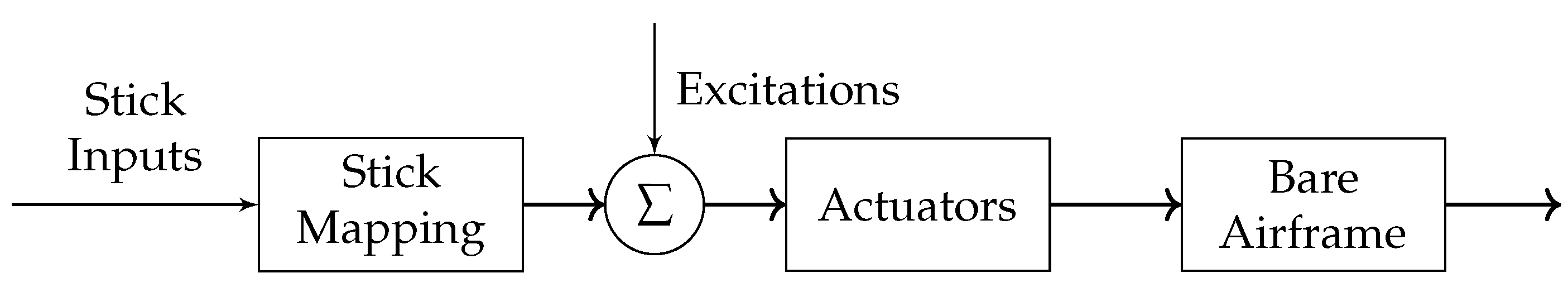
5.1. Maneuver Evaluation
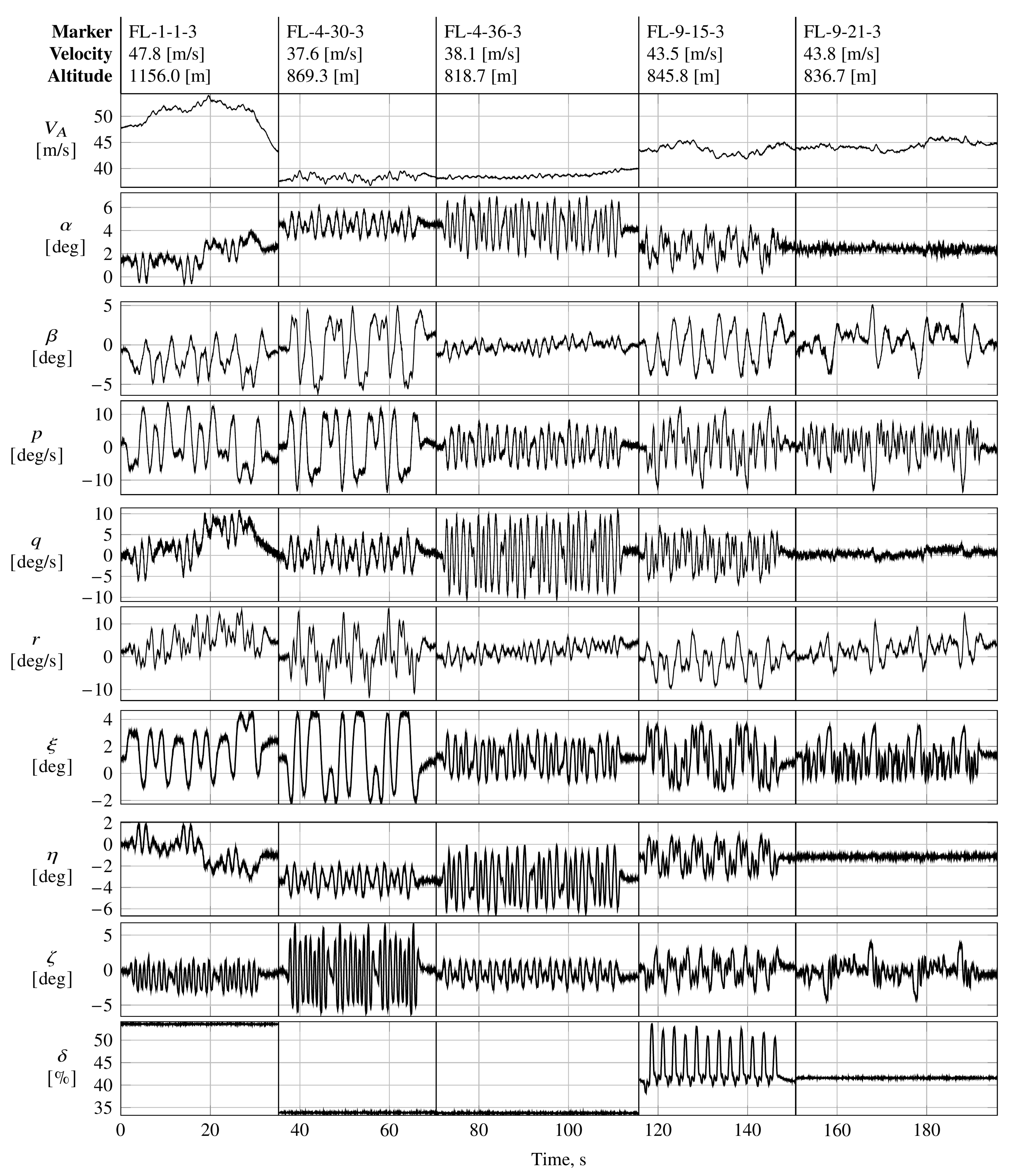
Figure A5 presents the flight data obtained from various longitudinal and lateral frequency sweeps designed to excite the longitudinal and lateral motion of the aircraft, respectively. The sweeps were injected into the elevator, aileron, and rudder separately during steady-state wing-level flight. Unlike the longitudinal sweeps applied to the elevator, the frequency sweeps applied to the aileron and rudder targeted towards the lateral modes of interest, respectively, also excited off-axis rates.
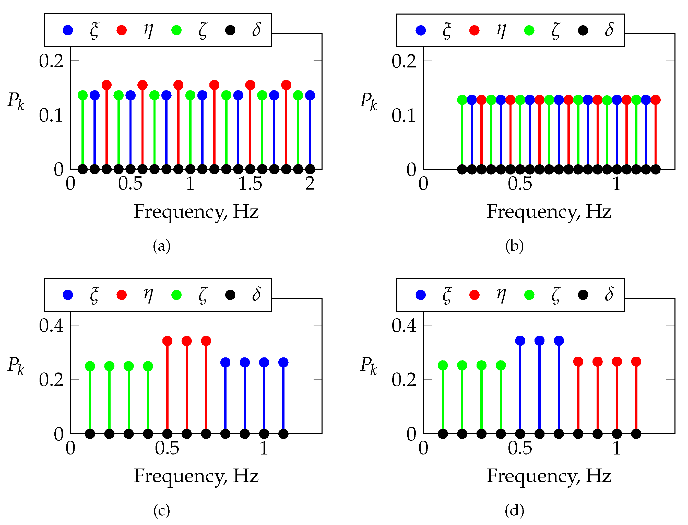
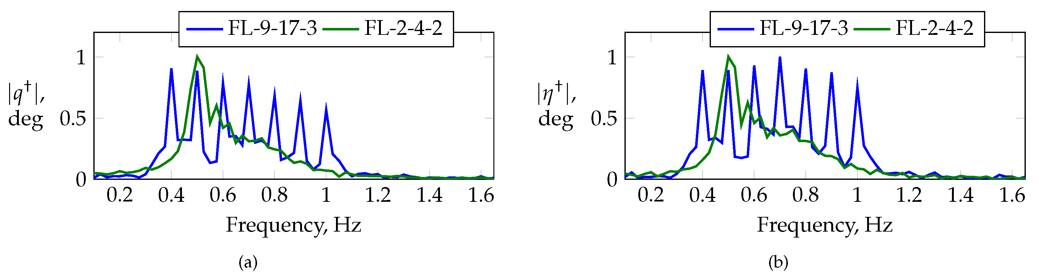
Figure 15 compares the frequency spectra for maneuvers FL-2-4-2 and FL-9-17-3. Maneuver FL-2-4-2 is a linear frequency sweep applied to the elevator, and maneuver FL-9-17-3 is an orthogonal multisine optimized for a low relative peak factor with an alternating frequency distribution among all of the longitudinal control inputs, i.e., the elevator and thrust lever. Both maneuvers were designed to excite frequencies in the vicinity of short-period motion, i.e., frequency bandwidths of
for maneuver FL-2-4-2 and
Hz for maneuver FL-9-17-3, with similar control amplitudes of 2
of excitation for maneuver FL-2-4-2 and 2.5
for maneuver FL-9-17-3. Multisine FL-9-17-3 was designed with a uniform power distribution over all of the control effectors and frequencies, respectively. The frequency range around the short-period region is excited well with both maneuvers; however, higher frequencies are excited better when using the optimized multisine. The latter also clearly excites the discrete frequencies applied by the elevator. A limitation in bandwidth is also visible around 0.7
.
The effectiveness and performance of both maneuvers were compared by estimating a single-point aerodynamic model for the vertical force coefficient
Both maneuvers had identical excitation times of 30
and similar input amplitudes and generated similar aircraft responses in terms of the longitudinal explanatory variables. Both maneuvers produced different information content in the frequency domain due to their different input energy distributions—cf.
Figure 15—which is why the following analysis was executed in the time domain. The comparison of both inputs, although both have different input energies, is consistent with the argumentation provided in Ref. [
1]. The parameters of Equation (
14) were estimated using the equation error in the time domain, as described in Refs. [
1,
3].
Table 7 summarizes the estimation results obtained for both maneuvers, respectively. In addition, the sums of the parameters’ standard errors are provided for both maneuvers. The multisine was shown to provide lower estimation errors for almost all of the parameters, except for
. Most of the parameters are in statistical agreement between both maneuvers, except for
, which is far away from the value obtained using the multisine for the frequency sweep.
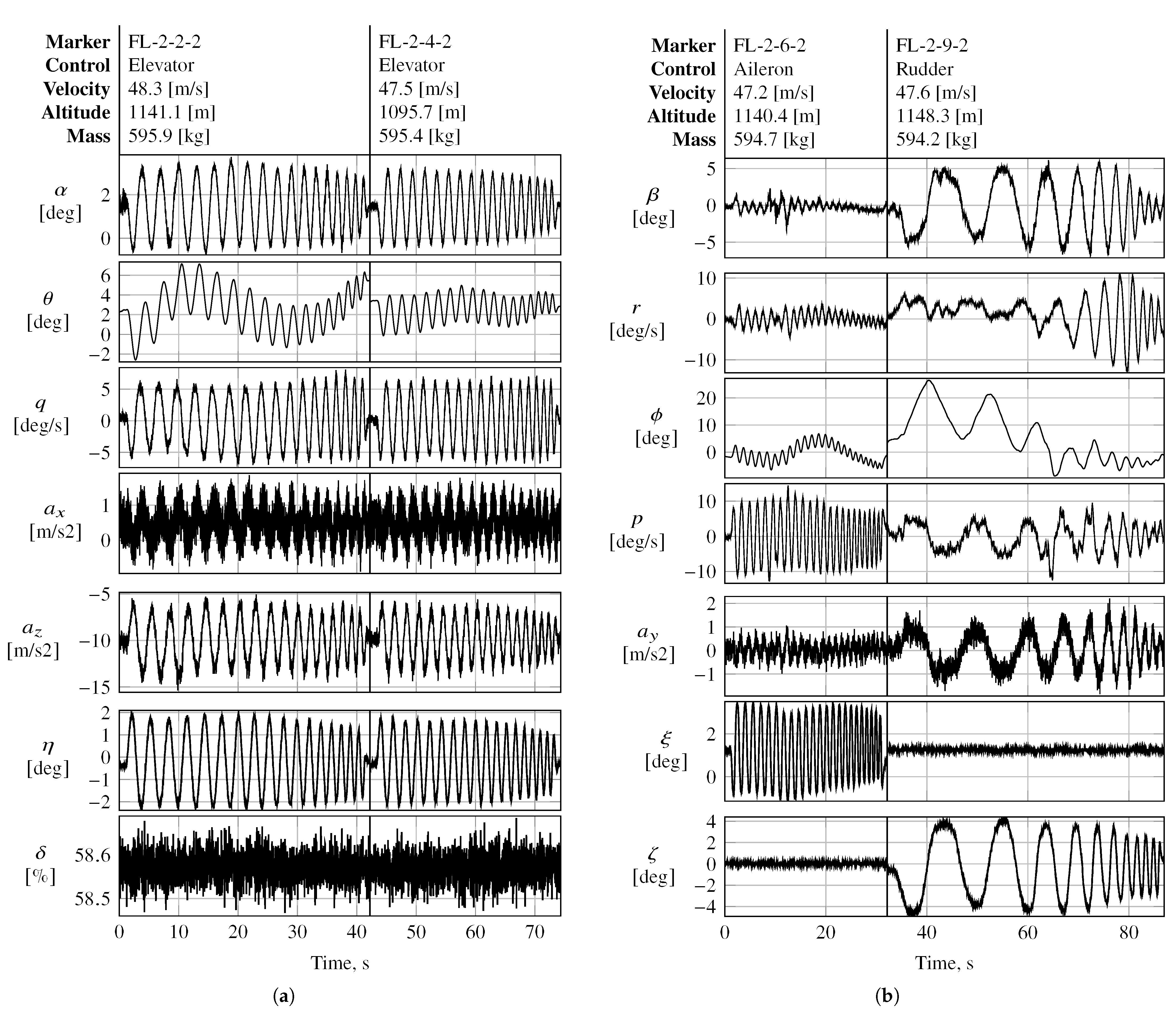
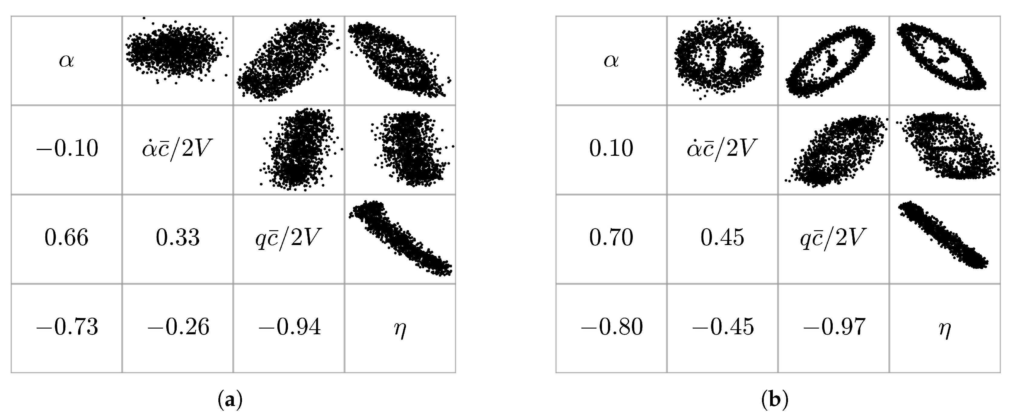
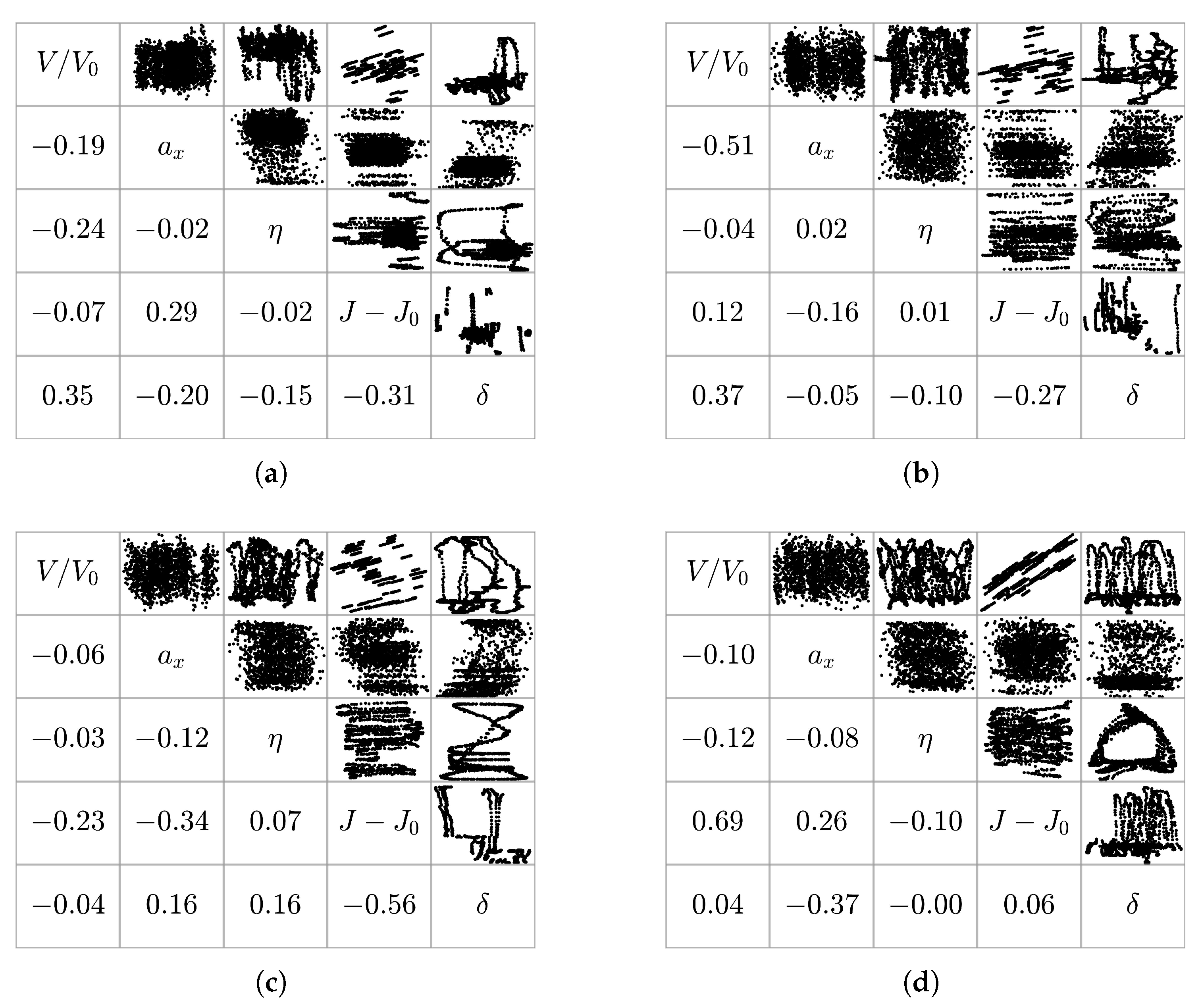
Figure 16 shows the regressor cross plots for both maneuvers, respectively. The multisine maneuver produces pairwise correlation values less than or equal to those obtained with the frequency sweep, while the largest reductions in the absolute pairwise correlation are observed for the regressor pairs
–
,
–
, and
–
. Regressors
–
are close to the common threshold of
for the flight data obtained using the frequency sweep.
The low bandwidth of the actuators was also a major issue when using multisteps to excite fast dynamic modes such as the short-period mode.
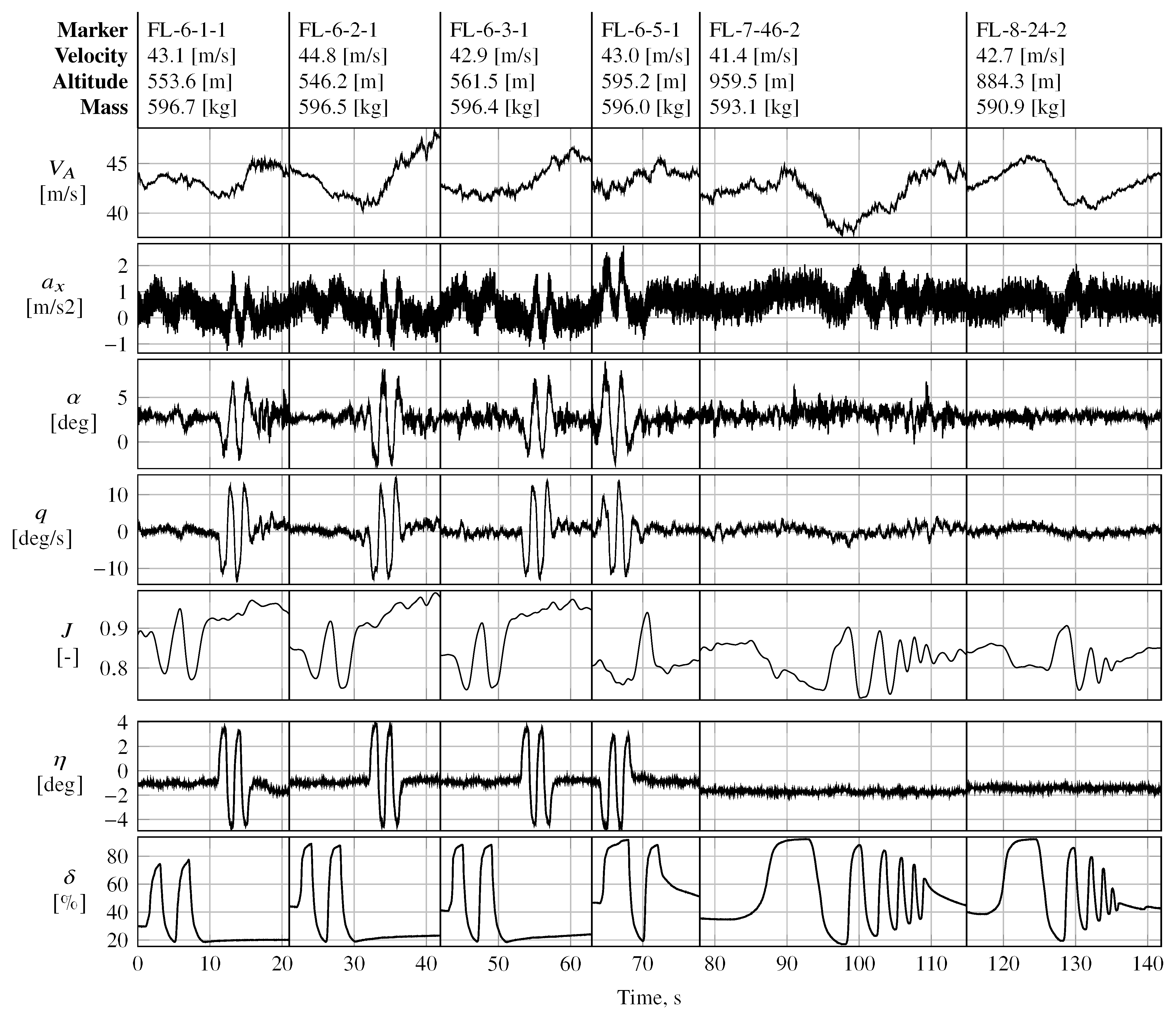
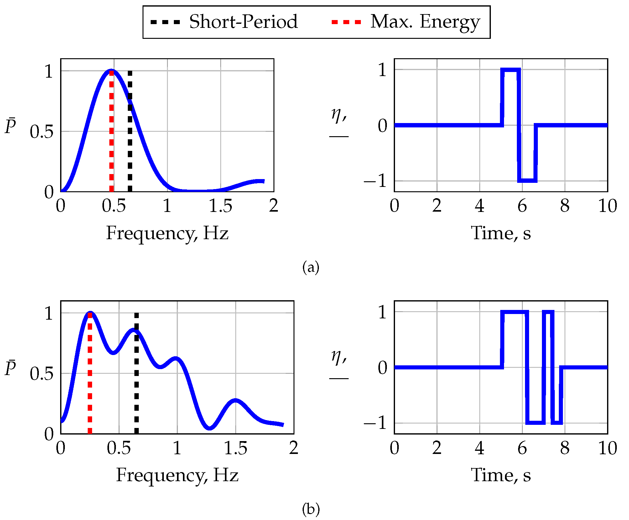
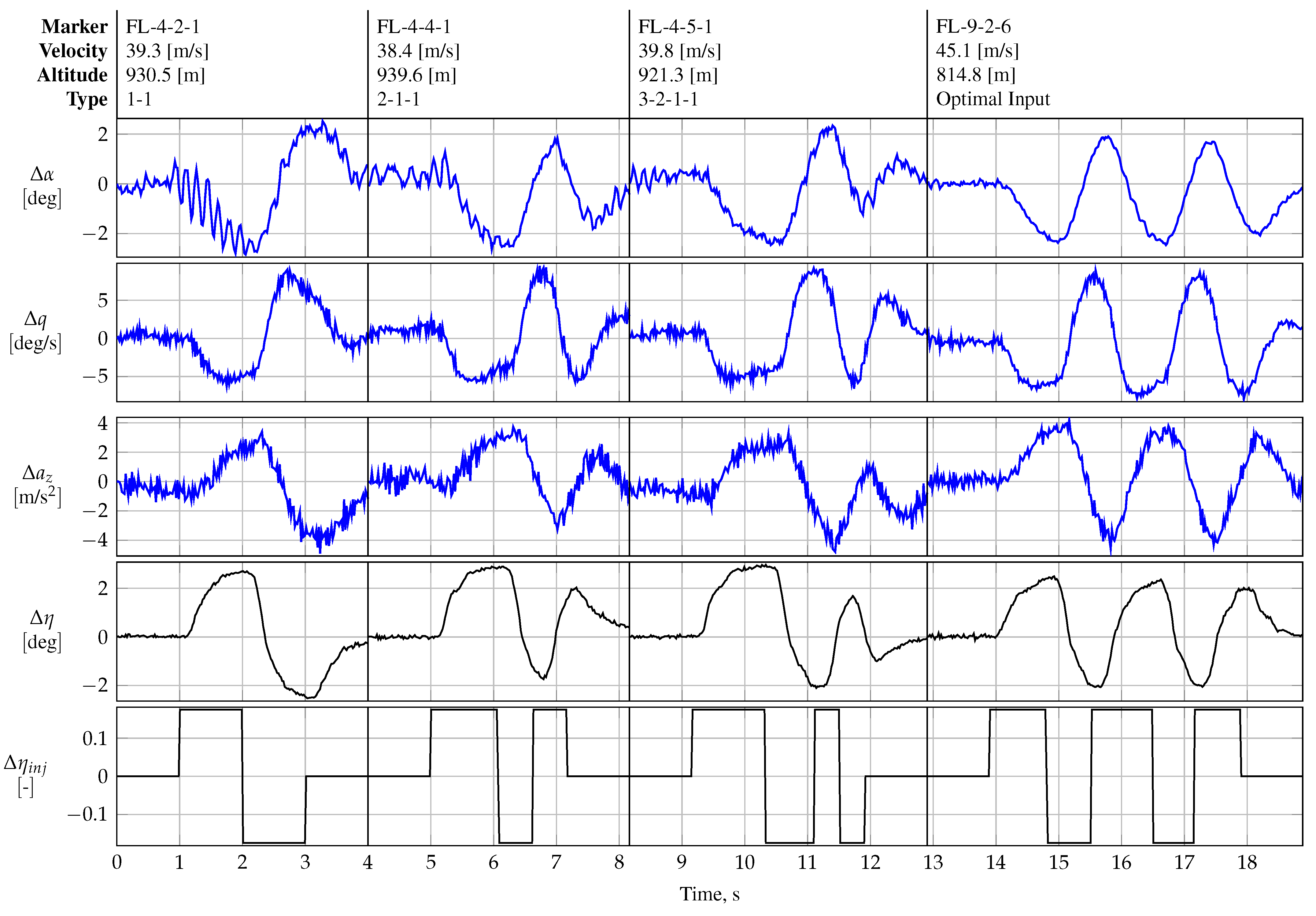
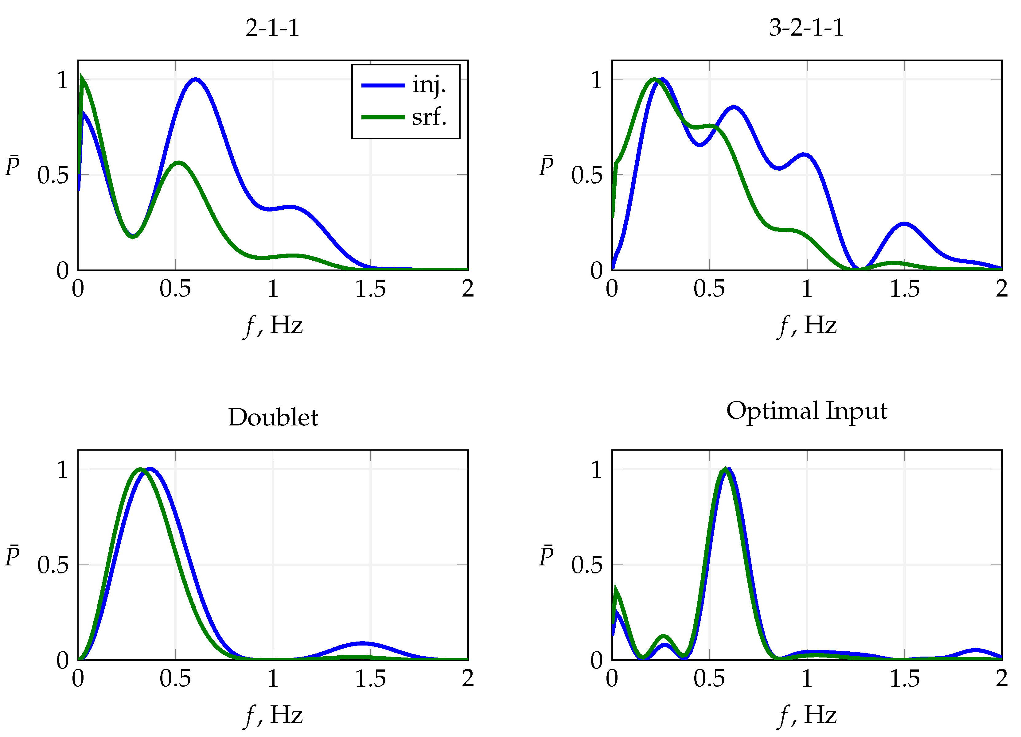
Figure 17 presents the in-flight performance of multistep maneuvers FL-3-1-1 and FL-3-3-1, both designed to excite the short-period mode; cf.
Figure 12. Maneuver FL-3-1-1 is a conventional doublet multistep with a fundamental time step of 0.76
for exciting a short-period frequency of approximately 0.65
.
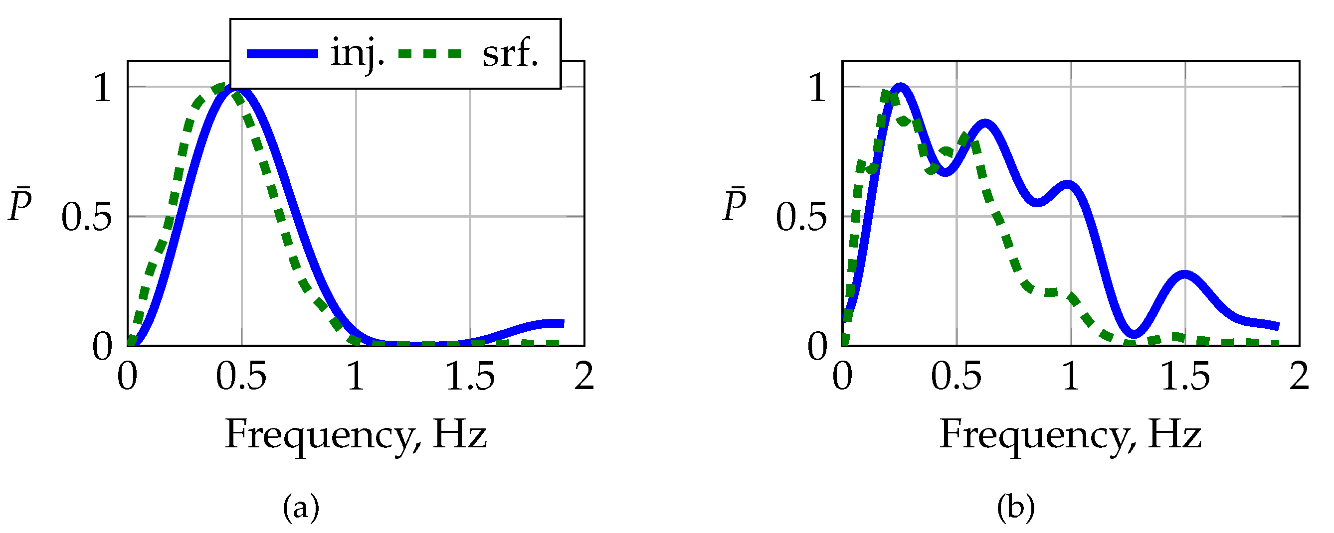
Figure 17 presents the normalized frequency transform of the injected and measured elevator deflections and their respective time histories. The actuator is not able to follow the command properly, indicated by the lagged and alternated surface deflection. Although the actual surface deflection lags behind the commanded deflection, the excited frequency almost matches the target frequency. Maneuver FL-3-3-1 is a 3-2-1-1 maneuver that also targets the short-period mode, with a shorter fundamental step width than that of FL-3-1-1 in order to bracket the short-period frequency with the slower and faster pulse of the 3-2-1-1 sequence. The slow actuator response excites the commanded multistep poorly; cf.
Figure 17. The latter is also visible in the sudden drop in the power distribution around
, which is shown on the left-hand side in
Figure 17, which is why the 3-2-1-1 maneuver could not excite the short-period mode at all.
As expected, multisteps performed significantly better in exciting slower dynamic modes, e.g., phugoid motion.
Figure 18 shows the flight data obtained after the execution of the FL-4-9-1 maneuver, which was designed to excite phugoid motion in the REMOS GX; cf.
Figure 11. Maneuver FL-4-10-1, as shown in
Figure 18, is a direct repetition of maneuver FL-4-9-1, with the goal of shifting the maximum injected power to higher frequencies. Both maneuvers excite phugoid motion; however, maneuver FL-4-9-1 performs better than its repeated version.
Multistep maneuvers designed to excite the dominant lateral modes did not result in any loss of the input energy.
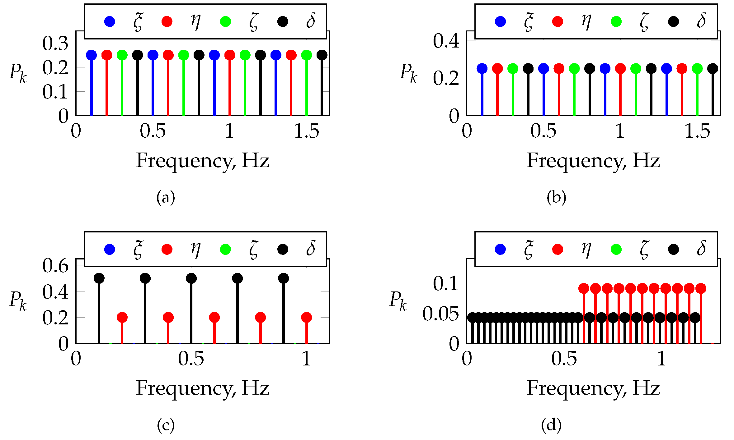
Figure 19 presents the normalized power spectra for three different orthogonal multisteps applied to both the aileron and the rudder in a time-skewed manner to excite the lateral dynamic modes, e.g., Dutch roll and roll mode. The main reason for the better excitation was that higher frequencies of interest (e.g., roll mode) were assigned to the aileron input, which had a significantly higher bandwidth compared to that of all other actuators, and the designed multistep could therefore be injected properly. Lower lateral frequencies of interest (e.g., Dutch roll) were assigned to the rudder input, which had no difficulties in exciting low-frequency multisteps.
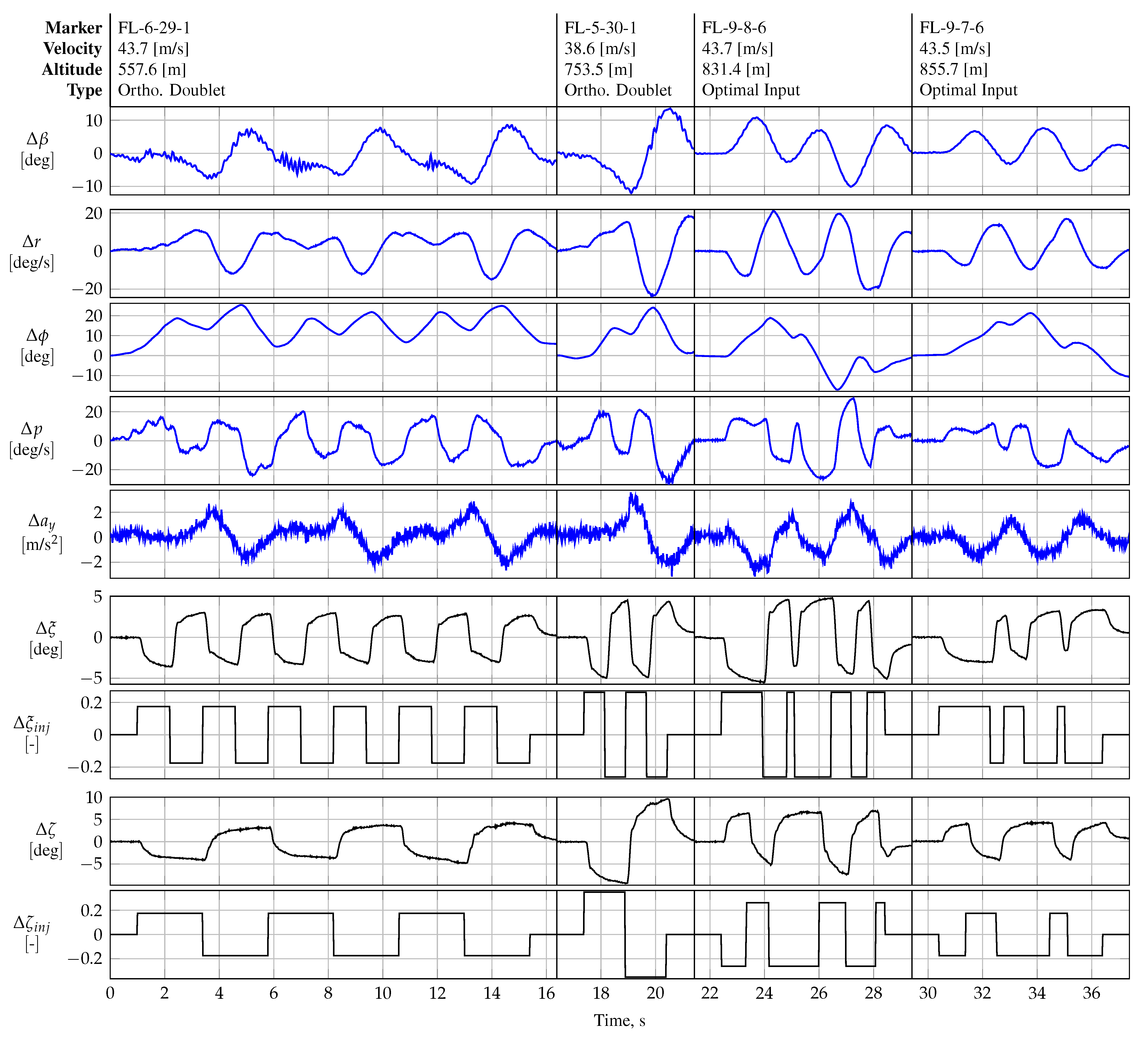
Figure 20 presents the flight data for maneuvers FL-4-23-1, FL-5-30-1, and FL-6-29-1. All three maneuvers presented were designed to be orthogonal to each other in the time domain, i.e., to have an inner cross-product of zero. The longitudinal control effectors (elevator and thrust input) were kept in trim conditions, which is why
Figure 20 is reduced to the states for lateral aircraft. In all maneuvers, the duration of the aileron doublet is chosen to match half the duration of one rudder doublet. The time duration and amplitude of both the aileron and rudder inputs were also varied for all three maneuvers. Unlike all other maneuvers, maneuver FL-6-29-1 was designed to shift the maximum input energy to a higher frequency by concatenating each doublet input sequence several times in time, i.e., six times the aileron sequences and three times the rudder sequences, respectively.
All three maneuvers shown in
Figure 20 showed low pairwise correlations among the lateral explanatory variables.
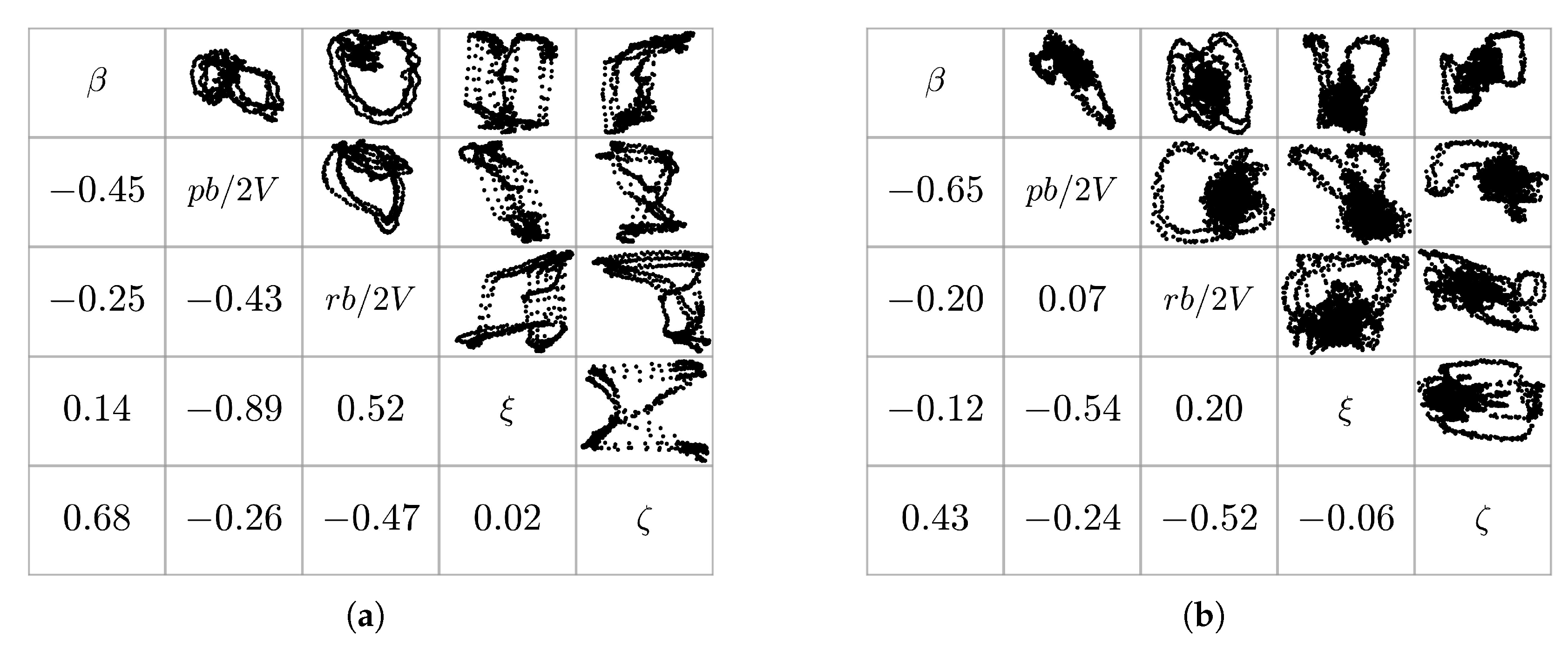
Figure 21 compares the pairwise correlations of the lateral explanatory variables of an optimized orthogonal multisine, designed for the aileron and the rudder only (maneuver FL-9-22-3), with those for the orthogonal multistep maneuver FL-6-29-1. Maneuver FL-9-22-3 was designed to excite roll and yaw motion in the aircraft in the frequency range of 0.05 to 2.00 Hz by manipulating only the lateral controls, i.e., the aileron and the rudder. The atmospheric conditions for both maneuvers were very similar in terms of wind and turbulence levels, producing similar signal-to-noise ratios. The optimized multisine shows lower absolute pairwise correlation values for all lateral regressor pairs. For most of the regressor pairs, however, the pairwise correlation values are similar between both maneuvers. The regressor pairs
–
r,
–
p, and
r–
p show the largest discrepancies between both maneuvers.
5.2. Improvements in the Experiments from Phase 1 Flight Tests
The frequency range used for the phase 1 flight test series was selected to correspond to the frequencies usually associated with the dominant frequencies of conventional aircraft configurations, which usually lie between 0.10 to 2.00 Hz (cf. Ref. [
1]). The maneuvers executed during the phase 1 campaign were used to correct and refine the assumptions about the frequencies of the dominant modes of the REMOS GX. The flight test time was critical and limited during phase 1, which is why a fast and top-level analysis of the aircraft’s dynamics was required to improve the excitation of the aircraft. The main analysis is therefore focused on the frequency responses and transfer function estimates. Phase-optimized orthogonal multisines were primarily used to update the initial information about the aircraft’s modes.
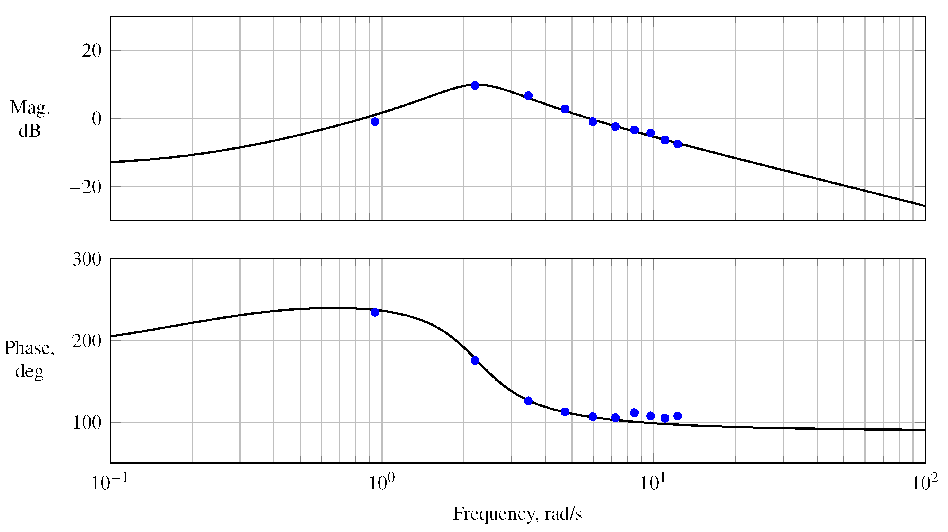
Figure A1 presents several phase-optimized orthogonal multisines designed for aerodynamic modeling (excluding thrust excitation) that were designed using the commonly known frequency spectrum mentioned before. The frequencies were assigned to each control input in an alternating manner, as well as by varying the frequency spectrum for each input, respectively. All maneuvers were designed using a uniform power distribution over all frequencies. Because the maximum number of frequencies was limited to 40 by the maneuver injection unit, the maximum number of frequencies, as well as the finest possible frequency spacing applied to each control effector, was also limited. Further restriction of the maximum and minimum frequency for excitation was therefore required to improve the aircraft’s excitation and the flight data’s information content, especially in the vicinity of the dominant modes. In terms of longitudinal motion, the most difficult mode to excite was the short-period mode. One approach to determining the short period’s frequency was estimating the transfer function between the elevator and the aircraft’s pitch rate. The transfer function from the elevator to the aircraft’s pitch rate is [
1]
where
is the short-period frequency, and
is the short period’s damping. The parameters of Equation (
15) were estimated using equation error parameter estimation in the frequency domain, following the recommendations provided in Ref. [
44]. The parameters estimated for the transfer function
are summarized in
Table 8 and correspond to a short-period frequency of approximately
Hz.
The estimated transfer function was validated against the frequency response estimated from phase-optimized multisines and multisteps from different maneuvers and showed good prediction capabilities. Orthogonal phase-optimized multisines offer various advantages for the computation of frequency responses. Since multisines excite a discrete set of frequencies, there is no need to apply spectral estimation methods that require windowing, averaging, and coherence weighting because the frequency response can be computed at the known excitation frequencies [
1,
44,
57]. Multisines also excite multiple inputs simultaneously (in contrast to frequency sweeps) and therefore reduce the required flight test time significantly. After detrending the explanatory variables in the time domain, the input
and the output
are transformed into the frequency domain utilizing the chirp z-transform applied at the known discrete input frequencies of the injected multisine, respectively. The frequency response is then computed from [
44]
The magnitude and phase of the estimated frequency response are given by [
1,
5,
44]
and are plotted against a logarithmic scale of the frequencies. The components
ℜ and
ℑ in Equation (
17) are the real and imaginary parts of a complex number, respectively.
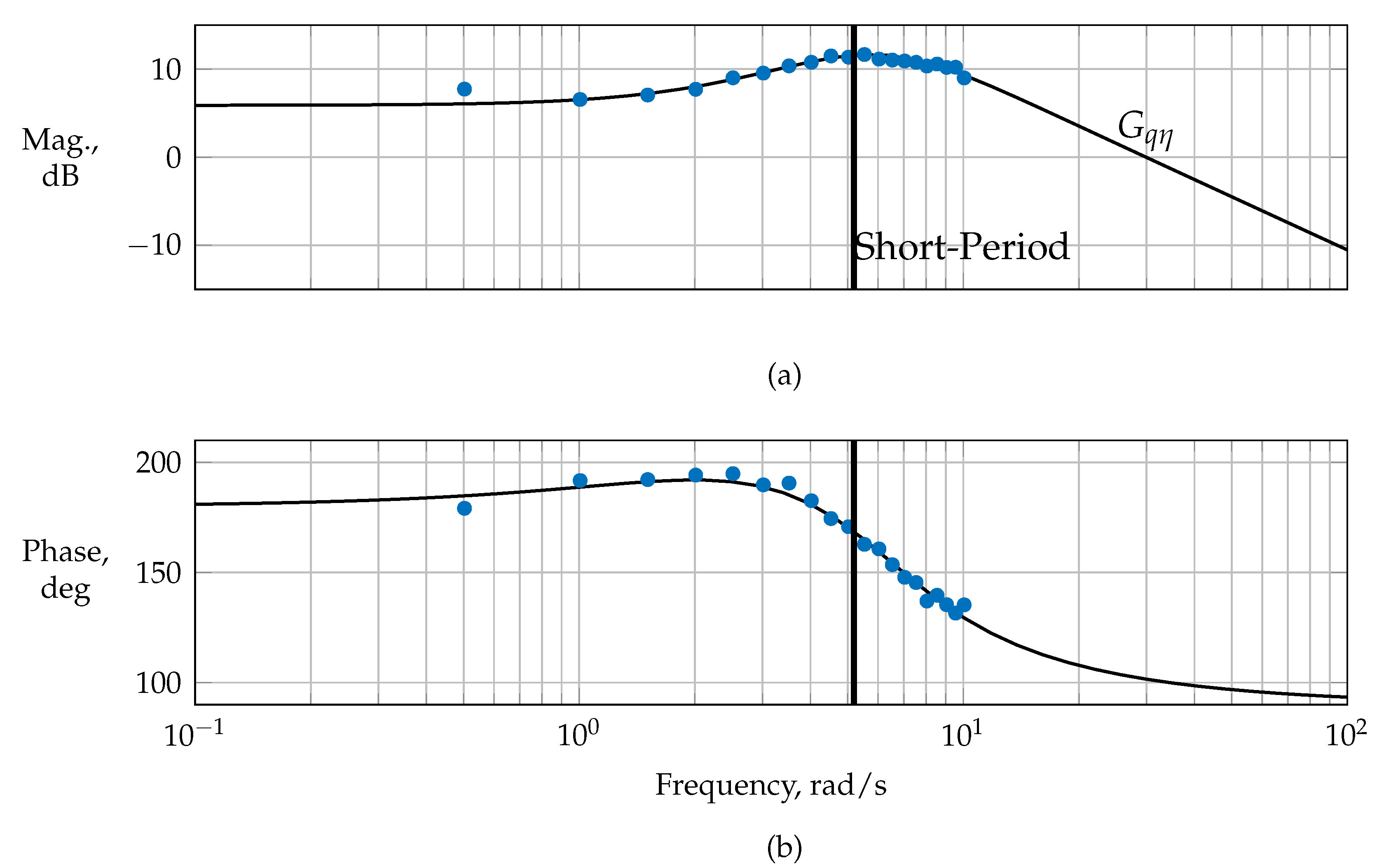
Figure A6 presents the estimated frequency response, magnitude, and phase for the estimated transfer function (cf. Equation (
15)). Analogously to longitudinal motion, the same analysis was performed for lateral motion—cf.
Figure A4—which yielded the estimated frequency response of the rudder to the yaw rate.
Table 9 summarizes the estimated bare-airframe frequencies for the dominant modes used to optimize the maneuvers for the phase 2 flight test series. Since phugoid motion could already be excited very well with the designed multisteps—cf. maneuver FL-4-9-1—no significant update to the phugoid frequency was recognized.
The optimization of maneuvers conducted in preparation for phase 2 focused on varying the excitation frequencies and input amplitudes associated with the maneuvers. The multisines designed for phase 1 were modified by varying the frequency bandwidth and refining the frequency spacing to effectively align the frequencies of interest with the corresponding control effectors. Due to the limitation on the maximum number of frequencies by the injection unit, multisines were also designed for only two control inputs, allowing for a finer allocation of frequencies to each individual control effector. As an example, multisines were also designed for aero-propulsive modeling exciting just the elevator and thrust input. Due to the reduction of control inputs, the frequency spacing could be refined for each input, improving the frequency content near the frequency of interest.
Figure A7 shows the estimated frequency response for an optimized multisine applied only to elevator and thrust. The shown input provides a finer frequency spacing around the estimated short-period frequency. In addition, linear models were estimated to further improve information about the frequencies of interest from maneuvers of phase 1. As an example, the short-period model for the REMOS GX was identified using the output error in the time domain. The results were presented in Ref. [
34] and are summarized in Equation (
19):
Similar analyses were performed for the dominant lateral modes. The estimation results obtained were used to verify the estimation results based on the frequency responses. Using updated and longitudinal multisines with refined frequencies, the magnitude and phase of
,
, and
were estimated.
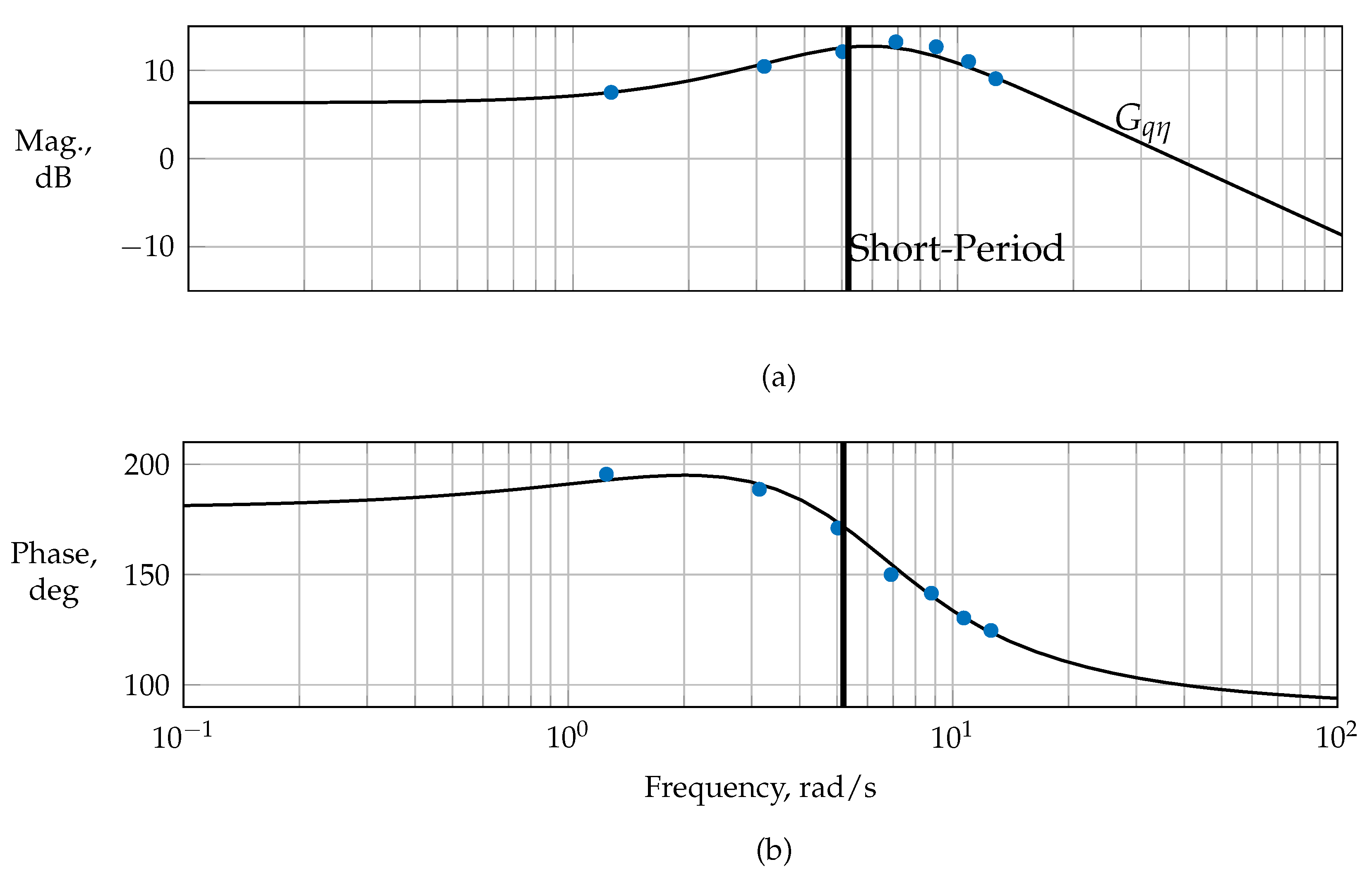
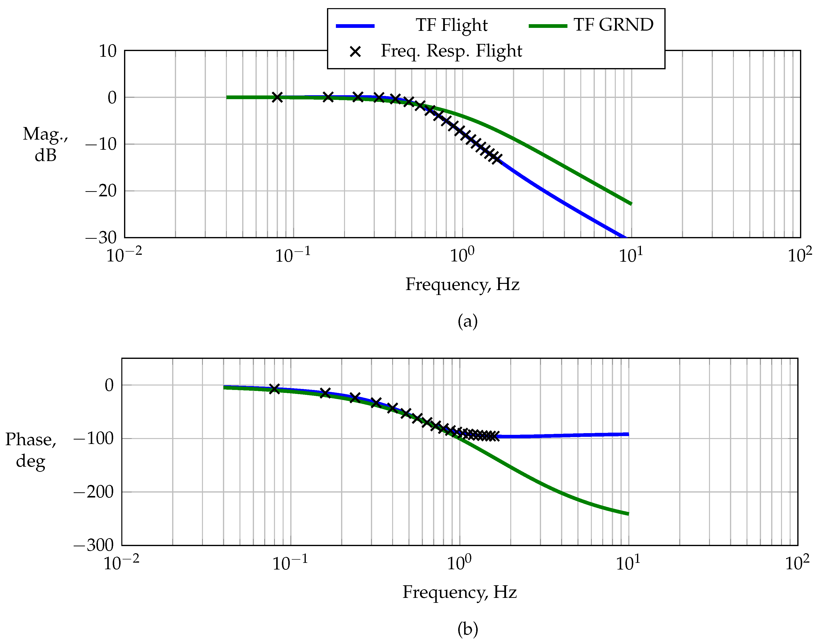
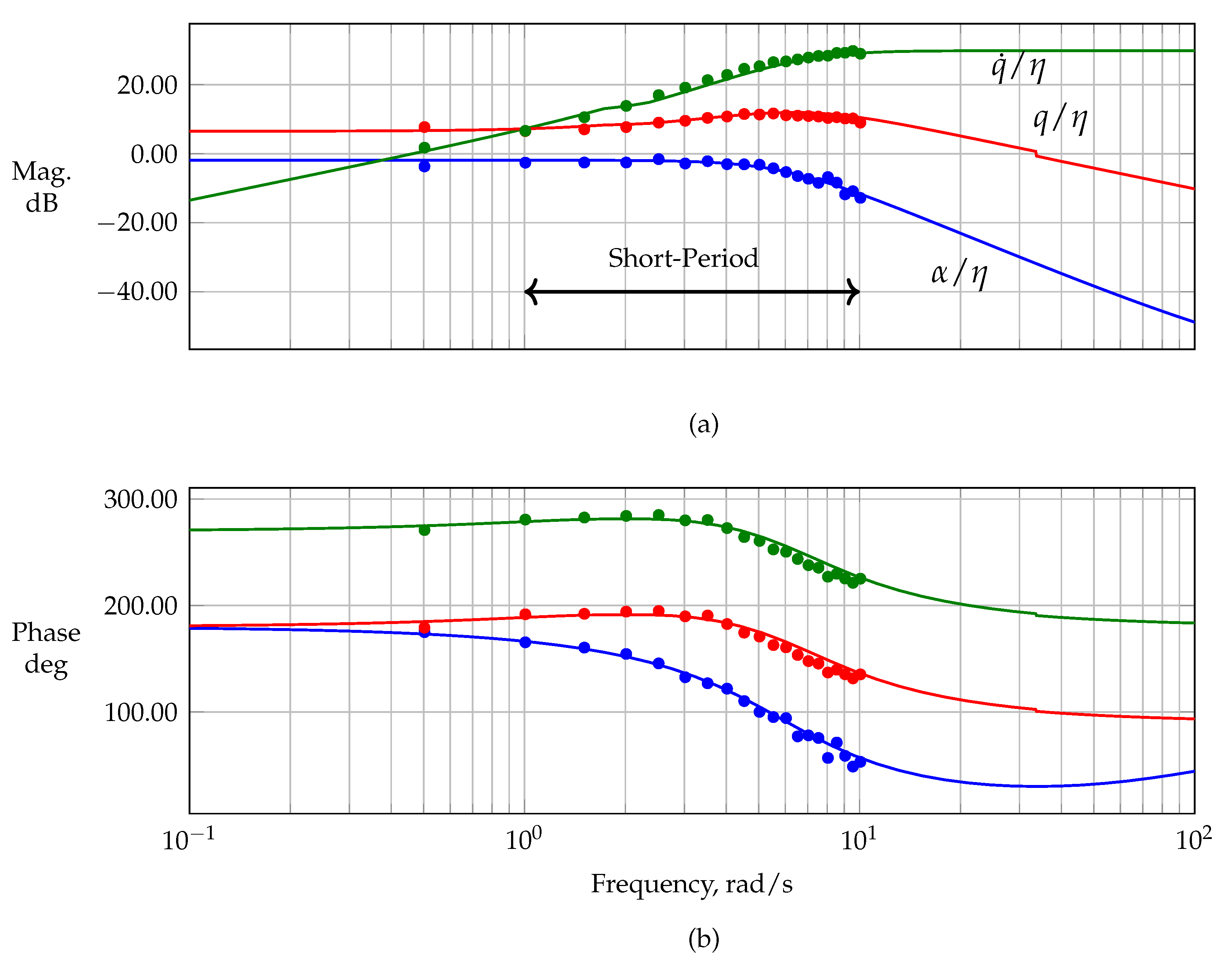
Figure 22 shows the estimated frequency responses against the magnitude and phase obtained from the identified linear short-period model from Equation (
19). The short period’s usual frequency range (cf. Ref. [
3]) was well covered by the updated refined multisine maneuvers. Although the actuators were limited in bandwidth, which at first degraded the quality of the multisteps for exciting short-period motion and imposed difficulties on its excitation, the multisines provided a good alternative for exciting the short-period mode with an acceptable information content.
5.5. Maneuvers for Aero-Propulsive Modeling
Figure A2 and
Figure A3 show the flight data obtained from the frequency sweeps, time-skewed longitudinal multisteps, and phase-optimized orthogonal multisines used for aero-propulsive modeling. The frequency sweeps and optimized multisines were used to identify the propulsive model, whereas the multisteps were used primarily to validate the identified model. The identified model structure, along with the estimated parameter values, is presented and discussed in Ref. [
30].
Maneuver FL-9-15-3 was designed as an orthogonal multisine with a conventional consecutive frequency distribution across all of the control effectors excited, i.e.,
,
,
, and
. This type of multisine was used primarily to identify any possible cross-coupling effects of the longitudinal motion, including the propulsive system with lateral motion. To decouple the longitudinal control effectors more effectively, i.e., the elevator
and the thrust lever
, several multisines were designed to excite the longitudinal motion only. The frequencies were either assigned in an alternating manner or through simple engineering judgment, as described previously in
Section 4.2.4. Maneuvers FL-9-12-3, FL-9-17-3, and FL-9-13-3 are shown as examples of the longitudinal phase-optimized multisines that were used for aero-propulsive modeling. Both maneuvers FL-9-12-3 and FL-9-17-3 were designed using alternating frequencies between the elevator and the thrust lever, whereas maneuver FL-9-13-3 excited the low-frequency spectrum only in the thrust lever channel. Maneuvers FL-9-12-3, FL-9-13-3, and FL-9-17-3 were designed to excite the longitudinal control inputs only, whereas FL-9-15-3 was designed to excite all controls. Maneuvers FL-9-13-3, FL-9-15-3, and FL-9-17-3 had a fundamental period of 30 s, respectively, while maneuver FL-9-12-3 was designed with a period of 50 s, reducing the frequency spacing of the frequencies excited; cf.
Figure 13. All maneuvers had roughly the same frequency bandwidth. All multisines shown were designed with different power spectra among the control effectors. In general, higher frequencies above 1 Hz were avoided for the thrust lever channel in order to minimize the total load acting on the engine and the propeller. Furthermore, lower frequencies applied to the thrust lever also resulted in a better response from the aircraft with respect to the injected input.
Input design metrics, e.g., the relative peak factor, the pairwise absolute correlation, and the variance inflation factor, quantify the efficiency and quality of a dynamic test input for exciting the system under test for system identification and parameter estimation.
Figure 27 presents the evolution of the commonly used input design metrics against time. Among others, the relative peak factor, the maximum absolute variance inflation factor
, the maximum absolute pairwise input correlation, and the condition number of the input matrix
are shown as a function of time for the different multisine designs designed for dynamic aero-propulsive modeling. All of these metrics were computed based on the actual measured control inputs. The relative peak factor of a signal
is defined as [
1]
and quantifies the ratio of the input signal’s amplitude range to its root mean square value, normalized to the peak factor of a single-frequency sinusoidal signal [
1,
58]. For system identification, an RPF value close to one is desirable, as this helps to keep the system close to its reference flight conditions [
51]. Low RPF values lead to a diminished peak-to-peak amplitude in the multisine excitation, consequently limiting the achievable temporal gradients of the signal. Mutual orthogonality remains unaffected regardless of the phase angles selected for the minimum RPF [
2]. However, due to the actuator dynamics, mutual orthogonality of the measured control inputs is not guaranteed. The correlation between two signals can be assessed using the pairwise correlation coefficient
[
1,
3]
where
and
are the mean values of the
j-th and
k-th regressors, respectively. As an alternative to the pairwise correlation coefficient, the variance inflation factor, defined as the diagonal elements of the
matrix, can be investigated [
1]:
where
is the coefficient of determination of the regression of the
j-th regressor, modeled as a linear function of all of the other regressors in the model [
1]. A
value of 1 indicates no correlation between the
j-th regressor and all other regressors, whereas a
value greater than 10 indicates high correlation, which is, however, always database-dependent [
1]. The pairwise correlation
and
can only be used to assess the correlation among two regressors and can therefore not guarantee that collinearity among more than two regressors is not present because mutual collinearity can be masked by other regressors. To address this shortcoming, the condition number
, defined as the ratio of the maximum to the minimum eigenvalue of the input matrix
, can be used [
1,
59]:
This is used to identify collinearity issues among the columns of
U. A value of
near one suggests low multicollinearity, while a high
value indicates a poorly conditioned estimation problem caused by collinearity. Depending on the dataset,
values between 100 and 100,000 are considered problematic [
1,
58].
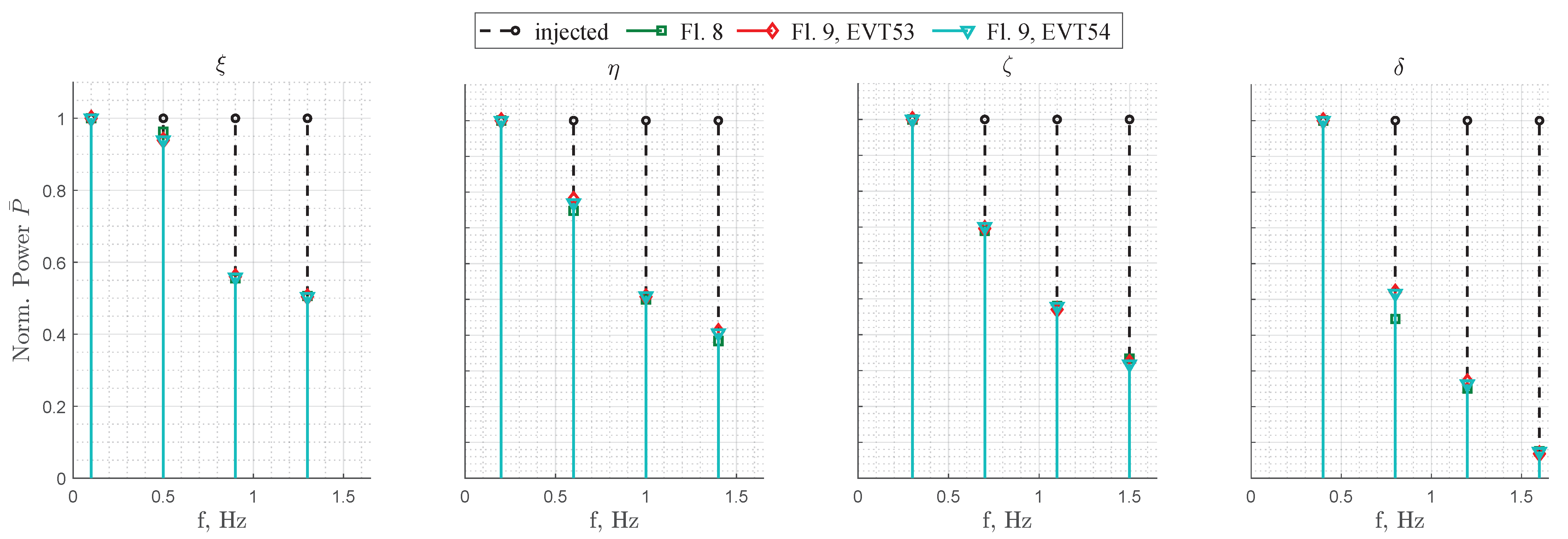
The maximum absolute pairwise correlation for all control effectors as a function of time is shown in
Figure 27a. For all multisines, the maximum absolute pairwise correlation values show a similar trend of decreasing toward low absolute correlation values. All multisines achieve a low correlation value after approximately 25 s, independent of their fundamental base period and frequency distribution. The maximum relative peak factor is shown in
Figure 27b. All multisines show a comparable trend of increasing slightly toward their designed peak factor. In summary, all multisines show acceptable peak factors around or below 1.5 after approximately 10 s. The maximum variance inflation factor
is shown in
Figure 27c. Only the two multisines with the highest base periods and the lowest frequency ranges achieve an acceptable maximum
value. All of the other multisines show significantly higher values, which is believed to be due to the sluggish response of the servo manipulating the thrust channel. The condition number of the input matrix
is shown in
Figure 27d. All test inputs converge to a constant condition number of approximately 100 or lower after approximately 10 s. Maneuvers FL-6-39-3 and FL-9-13-3 exhibit, in general, the lowest condition number of approximately 10. The condition number continues to decrease for all test inputs. In summary, optimized multisines with a lower frequency content and higher base periods revealed superior input design metrics for aero-propulsive modeling. Furthermore, guided by the results of this time-dependent analysis and corroborated by previous studies that have demonstrated the efficiency of an enhanced frequency spacing [
58,
59], multisines with higher fundamental periods were selected for aero-propulsive modeling.
Figure 28 shows the final cross plots of the propulsive explanatory variables for each maneuver, respectively. In general, all of the multisines showed good pairwise correlations among the aero-propulsive explanatory variables. Although the amplitude applied to the thrust lever was lower than that for the other maneuvers, maneuver FL-9-15-3 showed the best capability to decorrelate both longitudinal control effectors, which might be related to the fact that the propulsion system could respond to lower frequencies better with coarser frequency spacing. All of the other maneuvers discussed also showed acceptable correlation values but were designed with a finer frequency spacing, which meant they could not be excited precisely by the sluggish propulsion system.


