Abstract
Traditional multirotor UAVs (unmanned aerial vehicles) are inherently underactuated, with coupled position and attitude control, which limits their maneuverability in specific applications. This paper presents a fully actuated quadrotor design based on a swashplateless rotor mechanism. Unlike existing fully actuated UAV designs that rely on servo-driven tilt mechanisms, this approach minimizes additional weight and simplifies the structure, resulting in a more maintainable system. The design, modeling, and control strategies for the quadrotor are presented. Furthermore, we propose a decoupled control method to address the need for both fully actuated and underactuated modes. The control architecture employs parallel attitude and position control structures and decouples the two subsystems using a nonlinear dynamic inversion (NDI) method. A compensation module is introduced to address the constraints imposed by the maximum rotor deflection angle and the corresponding feasible force set. This compensation module actively adjusts the attitude to mitigate the saturation of the required thrust, effectively overcoming the impact of rotor deflection angle limitations on trajectory tracking performance. The approach facilitates seamless switching between fully actuated and underactuated modes, enhancing the system’s flexibility and robustness. Simulation and flight experiments demonstrate the effectiveness and performance of the proposed design.
1. Introduction
Multirotor unmanned aerial vehicles (UAVs) have found widespread application in fields such as post-disaster rescue [1], area search [2], military reconnaissance [3], target encirclement [4] and urban air mobility [5]. Traditional multirotor UAVs typically use fixed rotors aligned perpendicularly to the platform, achieving control through differential thrust. This configuration inherently couples position and attitude control, limiting maneuverability and preventing independent control over orientation and translation. Such limitations reduce effectiveness in complex scenarios, like navigating confined spaces while maintaining precise orientation, as required in search and rescue missions. To overcome these constraints, fully actuated UAVs that enable decoupled position and attitude control have attracted substantial research interest.
One widely adopted approach to improving multirotor UAVs for fully actuated control is to modify the original coplanar rotor configuration by fixing each rotor at a predetermined tilt angle. Such designs, often referred to as tilted-rotor UAVs, extend the control capabilities beyond those of conventional underactuated multirotor UAVs [6]. Other designs used ring-like rods to permit gradual tilt adjustments, facilitating shifts between traditional multirotor and fully actuated modes [7]. However, these fixed-tilt designs led to thrust inefficiencies, as the fixed angles caused opposing horizontal thrust components, resulting in energy losses and diminished maneuverability.
To improve flexibility, servo mechanisms were introduced for dynamic rotor tilting, partially decoupling position and attitude control. Some designs employed servos to tilt coaxial rotors along specific axes, allowing for independent translational control along the x-axis [8]. Other configurations permitted rotors to tilt along single axes, achieving limited decoupling and enhanced control [9,10]. More advanced fully actuated systems included designs like a quadrotor with a parallelogram structure, enabling rotor tilt along both x- and y-axes for more versatile control [11]. As UAV configurations advanced, practical applications such as robotic arm integration drove further innovation. These applications require stable control under environmental disturbances, leading to the development of robust controllers for fully actuated UAVs equipped with multi-degree-of-freedom robotic arms [12,13]. While servo-based designs offer greater control flexibility, the added weight of servos and tilting mechanisms significantly reduces flight range and payload capacity, limiting their practicality for extended missions.
In response to these challenges, an approach using a swashplateless rotor mechanism has emerged as a potential solution for achieving fully actuated control in multirotor UAVs. Paulos and Yim first introduced this mechanism [14,15] and applied it in a coaxial rotor system [16,17], later improving it by adding flapping hinges and developing comprehensive dynamic and kinematic models. Subsequent improvements, such as integrating teetering hinges [18], simplified the design and reduced mechanical complexity. Researchers applied this mechanism to single-rotor UAVs [19], while Qin [20] further improved the swashplateless system by eliminating dead zones in a bi-copter UAV, achieving nearly fully actuated control. However, it was still operated as an underactuated system.
This paper introduces a fully actuated quadrotor, as shown in Figure 1, which achieves decoupled position and attitude control using a swashplateless rotor mechanism. The main contributions of this work are summarized as follows:
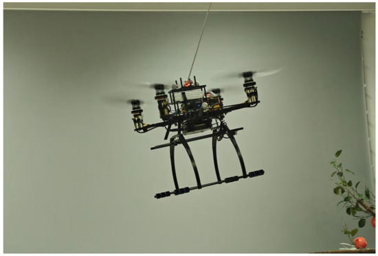
Figure 1.
The fully actuated quadrotor UAV.
- A novel fully actuated quadrotor design: A quadrotor UAV configuration is proposed based on a swashplateless rotor mechanism, enabling independent control of position and orientation. Unlike conventional fully actuated designs that rely on servo-driven tilt mechanisms and complex linkages, the proposed design replaces standard propellers with swashplateless rotors, resulting in a lighter, simpler, and more maintainable platform with minimal structural modifications.
- A decoupled control framework combining nonlinear dynamic inversion and disturbance estimation: A parallel control architecture is developed to decouple position and attitude dynamics using nonlinear dynamic inversion (NDI), replacing the traditional cascaded control structure. To further enhance robustness against model uncertainties and external disturbances, extended state observers (ESOs) are integrated to estimate and compensate for lumped disturbances in both attitude and position loops.
- An attitude compensation strategy for constraint handling and mode switching: An attitude compensation method is proposed to address the force constraints imposed by the maximum rotor deflection angle. This method actively adjusts the target attitude to ensure that the required force remains within the feasible set, mitigating the impact of maximum rotor deflection angle on tracking performance. The strategy enables smooth switching between fully actuated and underactuated modes, improving control flexibility in complex flight tasks.
2. System Architecture and Mechanical Design
Figure 2 illustrates the physical configuration of the fully actuated quadrotor. The UAV follows a standard quadrotor layout, with a 450 mm diagonal carbon fiber frame and a rotor span of 259 mm. The rotor system is designed with a maximum tilt angle of , ensuring adequate clearance to prevent interference with the arms during startup or when the rotors are at their maximum tilt. To mitigate the risk of damage, the distance between the rotor center and the arm is set at 95 mm.
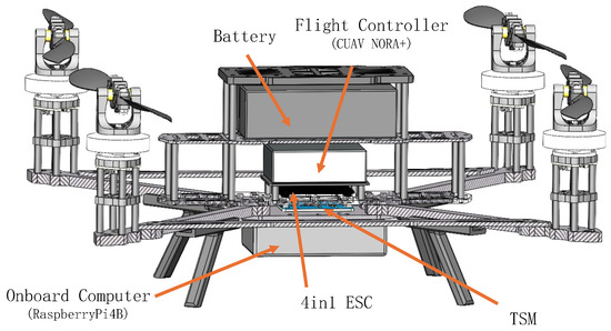
Figure 2.
Components of the fully actuated quadrotor UAV. The platform adopts a 450 mm wheelbase carbon fiber frame and uses the CUAV Nora+ as the flight controller. A Raspberry Pi 4B is used as the onboard computer for high-level tasks. A customized Throttle Signal Modulation (TSM) module is employed to bridge the flight controller and the 4in1 ESC, enabling periodic modulation of motor throttle signals. The propulsion system consists of brushless motors and swashplateless rotor mechanisms mounted at each corner.
2.1. Swashplateless Rotor System
The swashplateless rotor mechanism enables the generation of both thrust and control moments through cyclic pitch variation. Unlike conventional swashplate systems, which require active control via mechanical linkages and servos, the swashplateless design passively adjusts the blade pitch through inertial effects. This passive approach eliminates the need for additional actuators, simplifying the mechanical structure and reducing system weight.
As illustrated in Figure 3a, the rotor assembly consists of two blades—one designated as positive and the other as negative—each mounted on the rotor hub with passive hinges inclined at . These passive hinges allow the blades to respond independently to variations in rotor speed, utilizing inertial effects to induce differential thrust. This self-regulating blade motion forms the basis for cyclic pitch control.
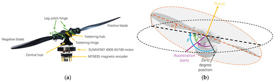
Figure 3.
Propulsion system of the fully actuated quadrotor UAV. (a) Structure of the rotor assembly. One positive blade and one negative blade are connected to the teetering hub via lag-pitch hinges, which are mounted at approximately relative to the blade plane. The teetering hub is further connected to the central hub through a teetering hinge. The SUNNYSKY 4006 KV740 motor [21] is used for actuation, with an MT6835 [22] magnetic encoder providing absolute angular position feedback. (b) Working principle. The rotor starts accelerating at position C. Due to inertia, the pitch angle of the positive blade increases while that of the negative blade decreases, causing the rotor disk to tilt around the teetering hinge. After a lag angle , the disk reaches its maximum deflection angle at position , resulting in a change in thrust direction.
The cyclic pitch control mechanism is governed by the inertial response of the blades to periodic rotor speed variations. When the motor undergoes periodic acceleration, the blades momentarily experience a phase lag due to their inertia. This lag results in an asymmetric pitch adjustment: the positive blade increases its pitch angle, thereby generating higher thrust, while the negative blade decreases its pitch angle, producing lower thrust. This differential thrust distribution creates a moment that tilts the propeller disk, thereby modulating the direction of the thrust vector, as shown in Figure 3b. A detailed analysis of this mechanism is provided in [20,23].
To actively control the tilt of the propeller disk, a sinusoidal modulation strategy is applied to the motor’s throttle command [20]. The throttle command U is defined as
where A represents the base throttle required to maintain a steady rotor speed, B is the amplitude of the modulation, determining the magnitude of cyclic variations, denotes the current angular position of the rotor, measured by the magnetic encoder, and C represents the angular position where motor acceleration begins.
A data-driven modeling approach is adopted to characterize the thrust and tilt angle behavior of the swashplateless rotor. This methodology aligns with established modeling practices for aircraft utilizing similar rotor mechanisms [19,20,23].
To accurately model the rotor dynamics, a two-step approach is adopted: (1) The approximately linear mapping between the control inputs A and B and the corresponding thrust T and deflection angle is analyzed; (2) Interpolation techniques are employed to model the deflection lag angle , capturing its nonlinear behavior. This combined approach provides a more accurate representation of the rotor’s dynamic behavior, accounting for both linear and nonlinear components.
As shown in Figure 4a, a linear relationship exists between the thrust T and the base speed A when the deflection angle is zero, which can be modeled as
where and are parameters obtained through linear fitting.
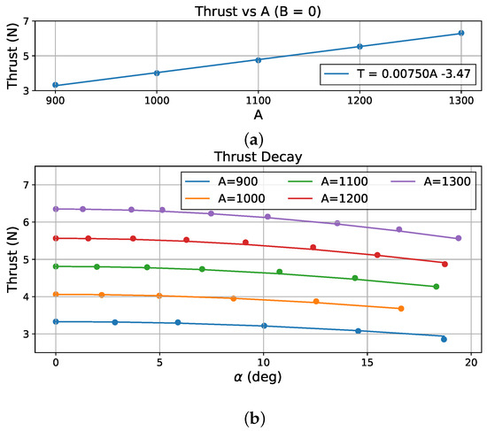
Figure 4.
Thrust mapping for the swashplateless rotor. (a) Thrust mapping under condition. (b) Thrust decay compensation.
As shown in Figure 4b, thrust T decreases as the deflection angle increases, preventing a direct mapping of thrust to the base speed A. To compensate for this thrust decay, an exponential decay function is introduced, modeled as
where is an experimentally determined decay coefficient.
The control input B represents the amplitude of the throttle modulation, while the deflection angle is approximately proportional to the ratio [19,20], modeled as
where is a constant determined through experimental data. The actual azimuth angle of the thrust vector, denoted by , is given by
where is a lag angle dependent on the values of A and B, and it can be calibrated using experimental data.
Adjusting A, B, and C, the propeller disk’s tilt angle and azimuth angle can be precisely controlled, allowing for fine adjustments in the thrust vector direction.
2.2. Avionics
The overall architecture of the avionics system is illustrated in Figure 5. The onboard system consists of a CUAV Nora+ [24] flight controller running a custom PX4 v1.15 firmware, a RaspberryPi 4B [25] as the onboard computer, and a NOKOV [26] motion capture system providing accurate position and attitude feedback via Wi-Fi. A radio module using the CRSF protocol is connected to the flight controller for remote control. Communication between the onboard computer and the flight controller is realized via the MAVLink protocol.
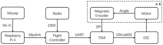
Figure 5.
Avionics architecture of the fully actuated quadrotor UAV. The RaspberryPi 4B receives external pose feedback from the motion capture system over Wi-Fi and communicates with the CUAV Nora+ flight controller via MAVLink. The TSM module receives control commands via UART and encoder feedback via SPI, then generates sinusoidal throttle signals sent to the ESC through the DShot600 protocol. Each of the four rotor units contains a magnetic encoder and a motor, forming a closed-loop control system for thrust vectoring.
Each propulsion unit includes a magnetic encoder (MT6835) that measures the real-time angular position of the rotor shaft. These signals are read through the SPI interface by the custom-designed Throttle Signal Modulation (TSM) module, which also receives control instructions from the flight controller via UART. The TSM module synthesizes sinusoidal throttle signals according to Equation (1), and sends motor commands to the 4-in-1 ESC using the DShot600 protocol. The ESC then drives the brushless motors to achieve the desired periodic modulation.
This modular design, with signal processing offloaded to the TSM, significantly reduces the computational burden on the flight controller and ensures reliable high-frequency execution (10 kHz) of rotor control. The magnetic encoder provides 21-bit resolution and operates at 10 kHz, allowing nearly 100 angular updates per revolution at hovering speeds, enabling fine-grained closed-loop speed control.
2.3. Weight
The fully actuated quadrotor designed in this work has a total mass of , which is comparable to the weight of mainstream 10-inch quadrotors. The weight of the major components of the UAV is summarized in Table 1.

Table 1.
Weight of individual components of the UAV.
The swashplateless rotor components are fabricated from PETG material using 3D printing, with each rotor weighing . Compared to the weight of mainstream 10-inch propellers and their mounting fixtures, which weigh approximately , the cyclically variable deflection rotor adds only a small increase in weight. Although additional components such as the magnetic encoder, the TSM module, and the motor mount raise the overall weight by approximately , or about of the total UAV weight, this increase is relatively small compared to the weight increase in fully actuated designs based on servo-driven mechanisms. Moreover, by optimizing the structure and materials of the motor mount, the additional weight can be further reduced.
This design eliminates the need for complex mechanical systems and additional servos, providing a lightweight solution for generating both thrust and moment in a fully actuated quadrotor.
3. System Modeling
To facilitate understanding of the mathematical derivations and notation throughout this section, the following convention is adopted for coordinate transformations and symbolic representation. A rotation matrix from frame to frame is denoted by , where the superscript indicates the destination frame and the subscript denotes the source frame. Standard axis-based rotation matrices, such as , are used to denote a rotation of angle about the z-axis of the relevant frame. Similar definitions apply to and .
To describe the dynamics of the fully actuated quadrotor UAV, three coordinate frames are defined: the body frame, the hub frame, and the rotor frame, as illustrated in Figure 6. The body frame, located at the UAV’s center of mass, has its x-axis pointing forward, y-axis to the right, and z-axis downward.
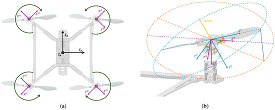
Figure 6.
Coordinate system of the fully actuated quadrotor UAV. (a) The body frame and hub frames for each rotor, with hub frames aligned based on the quadrotor structure. (b) The rotor frame aligned with the rotor disk, which is oriented relative to the hub frame by an azimuth angle and a tilt angle . The orientation is achieved through an initial rotation around the z-axis by , followed by a rotation around the y-axis by . The dashed circular outlines represent the approximate rotor planes, while the three dashed lines depict the progression of the x-axis: purple for , orange for the rotated X-axis after , and blue for , the rotated x-axis after .
Each hub frame is attached to the rotor’s central hub, located at the intersection of the motor shaft and the rotor’s teetering hinge. The position of the hub frames relative to the body frame is given by , where l is the lateral distance from the UAV’s center of mass, h is the height offset, and is the rotation angle of each hub frame relative to the body frame (). The rotation matrix from the body frame to the hub frame is as follows
The rotor frame is aligned with the rotor disk and tilted relative to the hub frame by the azimuth angle and tilt angle . An initial rotation around the z-axis by achieves this orientation, followed by a y-axis rotation by
The complete transformation from the body frame to the rotor frame is then given by
The thrust vector generated by each rotor in the body frame is defined as
where represents the thrust and is the unit vector along the z-axis.
The torque exerted by each rotor is given by
where the notation denotes the skew-symmetric matrix associated with a vector, is the identity matrix, is an empirically determined proportionality constant, and indicates the rotor’s rotation direction (, , , ).
The UAV’s net force and net torque are the sums of the individual rotor contributions
The dynamics of the UAV are described by the Newton–Euler equations. Let the UAV’s position in the world frame be represented by , and its attitude by the rotation matrix , with denoting the angular velocity in the body frame. The UAV dynamics are then expressed as
where m is the UAV’s total mass, g is the gravitational acceleration, and is the positive-definite inertia matrix. The terms and represent external disturbances acting on the UAV.
4. Controller Design
In many mission scenarios, quadrotors must alternate between fully actuated and underactuated modes to meet diverse flight requirements. Fully actuated control is crucial for tasks such as target search and tracking, where precise attitude adjustments are required to maintain sensor alignment. In contrast, underactuated flight is more energy-efficient and suitable for transitions or low-demand phases. This necessitates a control strategy capable of smoothly switching between modes.
However, trajectory tracking performance is often limited by the maximum allowable rotor deflection angle, which constrains the feasible set of thrust directions. To address this, a hybrid control approach is required—one that combines the maneuverability of fully actuated systems with the efficiency of underactuated configurations. Given the differences in control input structures and actuation capabilities between the two modes, designing a unified framework that can handle both remains a key challenge.
Traditional cascade controllers are insufficient for such fully actuated platforms, where position and attitude control must be decoupled to fully exploit the system’s capabilities. To this end, a novel control architecture is developed, as shown in Figure 7, featuring parallel position and attitude control loops coordinated by an attitude compensation module. This structure supports hybrid mode control while maintaining robustness and precision in both actuation regimes.
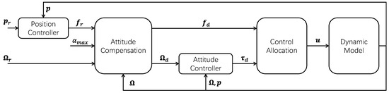
Figure 7.
Control architecture of the fully actuated quadrotor UAV.
In the proposed control framework, the reference position and current position are processed by the position controller to compute the required force . When exceeds the feasible set constrained by the maximum rotor deflection angle , the attitude compensation module adjusts the reference attitude to a modified target , ensuring that the corrected force command remains within the admissible range.
The attitude controller then uses and the measured attitude to generate the required torque command . The feasible force and torque are subsequently passed to the control allocation module, which computes the low-level control input , including rotor speeds and modulation parameters necessary for actuation.
4.1. Attitude Compensation
In complex environments, the required net force and torque may exceed the system’s feasible set , particularly during large-angle maneuvers or under strong disturbances. This results in rotor deflection saturation, causing the actual generated force and torque to deviate from the control demands, which degrades trajectory tracking and overall flight stability.
To address this, an attitude compensation strategy is introduced to ensure that the corrected force command remains within the feasible set. As shown in Figure 8, when lies outside , the compensation module actively adjusts the target attitude to a new orientation , such that the thrust direction (denoted by the unit vector ) is rotated toward the direction of , thereby bringing the force into the feasible set . A corresponding force correction is also applied to ensure satisfies the actuation constraints.
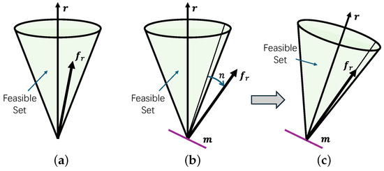
Figure 8.
Attitude compensation strategy for adjusting the UAV’s orientation. (a) No compensation required; (b) Before compensation; (c) After compensation.
The compensation procedure involves two steps: adjusting the reference attitude to and modifying to obtain . The adjusted attitude is computed via a rotation about a unit axis by an angle n:
where the rotation matrix represents a rotation by an angle n about the unit vector , and is computed using Rodrigues’ formula [27]
The unit rotation axis is defined as
The rotation angle n is the adjustment required for to enter the feasible set, defined as the difference between the current angle and the maximum allowable tilt angle
where is the maximum allowed tilt angle, and is the angle between and the required net force
Once the target attitude is adjusted, the force is projected to remain within . The corrected force command is defined as
This control approach requires to ensure the thrust direction maintains a negative component along the body z-axis, i.e., . This condition can be satisfied through input constraints or appropriate reference generation.
As shown in Figure 9, the control mode depends on the relationship between and : (1) Underactuated mode: , lateral forces are fully compensated by attitude adjustment (). (2) Fully actuated mode: , and , no compensation is needed (). (3) Hybrid mode: , and , requiring partial compensation ().
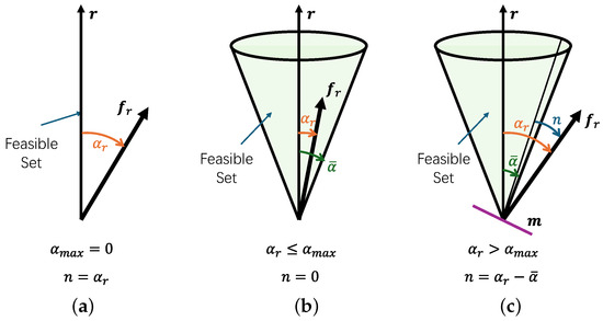
Figure 9.
Control modes of the fully actuated quadrotor UAV. (a) Underactuated mode; (b) fully actuated mode; (c) hybrid mode.
This control framework supports dynamic switching between modes by configuring , and is compatible with both fully actuated and traditional underactuated UAVs. It also enables coordinated operation in heterogeneous formations. By avoiding explicit switching logic in control allocation, the method reduces implementation complexity while ensuring smooth transitions and maintaining robust performance across varying flight regimes. This strategy prioritizes position tracking accuracy at the expense of exact attitude tracking, which is acceptable in many tasks where position performance is critical—such as flying in obstacle-dense environments.
4.2. Attitude Control
The attitude controller is designed to ensure that the UAV accurately tracks the desired attitude trajectory while maintaining stability and robustness in the presence of model uncertainties and external disturbances. The attitude tracking error is defined as , where denotes the desired attitude command.
Based on the system dynamics, the second-order error dynamics can be written as
where is the control torque to be designed, is the lumped unknown disturbance, and
To achieve accurate tracking and disturbance rejection, a control law based on NDI is employed
where is the virtual control input, and is the estimate of the lumped disturbance obtained from ESO. The virtual input is designed as
with , and . and are positive definite gain matrices.
To estimate , an ESO is constructed based on the error dynamics
where , and the extended state is defined as . The ESO is given by
where denotes the estimates of the states, and () are the ESO gain matrices. With appropriate gain design, the estimation error can be bounded [28] as
By incorporating the ESO-based disturbance estimate into the control law, the controller enhances robustness and maintains high tracking accuracy under external disturbances and model uncertainties.
4.3. Position Control
The position controller is designed to enable accurate trajectory tracking in three-dimensional space. The position tracking error is defined as , where is the current position of the UAV in the inertial frame, and is the desired position. Considering the UAV’s translational dynamics, the second-order error dynamics can be expressed as
where is the control force to be designed, and represents the lumped uncertainty, which includes model mismatches, external disturbances , and force allocation errors.
The NDI-based control law is adopted
where is the estimated disturbance from ESO, and is the virtual control input defined as
where is the velocity error and , are positive definite gain matrices.
To estimate in real time, an ESO is constructed based on the position error dynamics
where , and the extended state is defined as . The ESO is given by:
where () are the estimated states, and are the observer gain matrices. Proper design of these gains guarantees that the estimation error is bounded [28]:
where is the upper bound of the estimation error.
4.4. Control Allocation
The objective of the control allocation is to distribute the desired total force and torque across the four rotors by calculating the motor command parameters A, B, and C, as previously defined in Equation (1). To achieve this, a cascaded control allocation strategy is designed.
According to Equation (11), the contribution of reaction torques is omitted due to the small magnitude of , which can be considered negligible. Under this assumption, the mapping between the total desired force and torque in the body frame and the individual rotor forces is given by
The thrust vectors for each rotor, , can be determined by applying the pseudoinverse of the control allocation matrix. With these vectors, the required tilt angles and thrust magnitudes for each rotor are calculated as follows
Using these tilt angles and thrust magnitudes, the motor control commands A, B, and C are subsequently calculated based on experimental mappings.
As the tilt angle increases, the thrust generated by the UAV experiences a decay effect, as defined by Equation (3). To compensate, an adjusted thrust is calculated to represent the required thrust under a zero-tilt condition, defined by
By substituting into Equation (2), A is obtained. Given the proportional relationship between and , experimental data fitting is used to compute B for each combination of A and . Subsequently, lookup tables are used to obtain the phase lag , enabling calculation of C according to Equation (5). This completes the control allocation, mapping desired thrust and tilt angles to motor commands A, B, and C.
5. Simulation Results
To verify the effectiveness of the proposed attitude compensation strategy, a simulation was designed in which a fully actuated quadrotor UAV tracks a circular trajectory. The results were compared with and without the incorporation of the attitude compensation module under identical conditions. The simulation constructs a scenario where the UAV needs to adjust its target attitude upon reaching the maximum deflection angle in order to maintain trajectory tracking accuracy. The simulation is divided into two distinct scenarios: the first involves adjusting the maximum deflection angle limit to create a mode-switching scenario, while the second scenario triggers the maximum deflection angle limit using highly dynamic trajectory commands, thereby creating an attitude compensation scenario. These two scenarios are designed to validate the effectiveness of the proposed attitude compensation strategy for fully actuated quadrotors.
In the simulation, the radius of the circular trajectory is set to 1 m, and the UAV’s initial position is . The initial attitude is also , and the attitude reference remains constant throughout the simulation. The UAV starts from rest with an initial velocity of . The physical parameters of the UAV used in the simulation are listed in Table 2.
Table 2.
UAV Physical Parameters.
The controller parameters are configured as follows. For attitude control, the proportional gain vector is and the damping gain vector is . For position control, the gains are and . The ESO gains for the attitude loop are , , and ; for the position loop, the ESO gains are , , and .
5.1. Mode-Switching Scenario
By dynamically adjusting the maximum allowable rotor deflection angle , the fully actuated quadrotor is capable of switching between fully actuated and underactuated modes. To evaluate the performance of the proposed control strategy under different modes and assess the smoothness of transitions, a simulation is conducted using a time-varying deflection angle limit. The reference trajectory is a circular path of radius 1 m, described by m. The deflection limit (in degrees) is defined as
Figure 10 presents the simulation results. The shaded areas denote the UAV’s operating mode: blue for the fully actuated mode, red for the hybrid mode, and green for the underactuated mode.
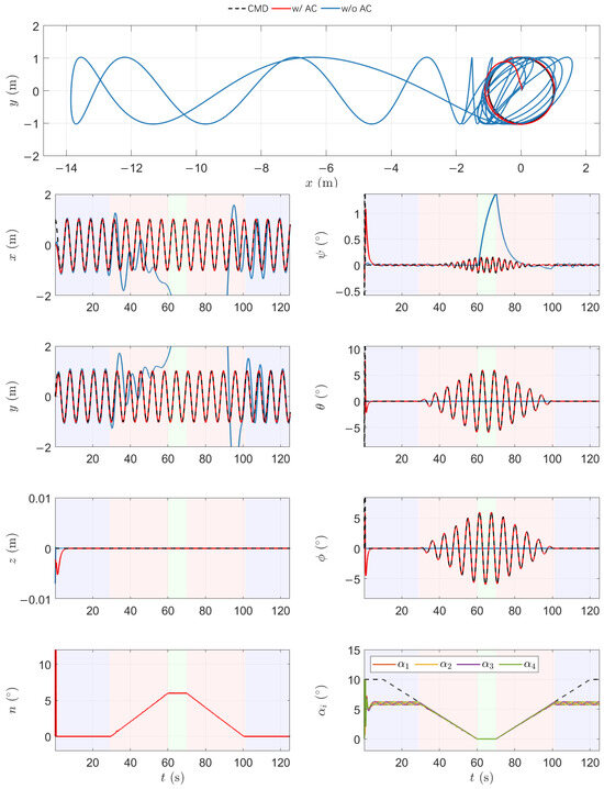
Figure 10.
Simulation results of the fully actuated quadrotor in a mode-switching scenario.
Initially, with , the system operates in the fully actuated mode. The rotor deflection angles remain within limits, enabling the UAV to generate the required lateral forces through tilt, while maintaining its attitude close to the reference. As decreases, the rotors gradually reach their deflection limits, and the UAV transitions into the hybrid mode. In this region, the required force can no longer be directly achieved by rotor deflection alone. The attitude compensation mechanism is activated to adjust the orientation dynamically, thereby maintaining trajectory tracking performance. During this phase, the required attitude adjustment angle n increases as compensation becomes more prominent.
When , the UAV enters the underactuated mode, in which all rotor tilt angles are fixed at zero. The system reverts to a standard quadrotor configuration, relying entirely on attitude changes to redirect the thrust vector. Although this requires larger attitude changes, the UAV remains capable of tracking the trajectory with high accuracy through continuous orientation adjustments.
For comparison, simulations without the proposed attitude compensation strategy show significantly degraded performance in the hybrid and underactuated modes. In the hybrid region, the inability to generate sufficient lateral thrust leads to increased position error and trajectory deviation. In the underactuated region, the tracking error diverges due to the lack of compensatory control authority.
These results demonstrate that the proposed control framework ensures stable and accurate tracking across all three modes. By continuously adapting the target attitude and projecting the required force within the feasible set, the control strategy achieves smooth transitions and robust performance throughout the mode-switching process. This capability is essential for real-world missions where the system must operate under varying actuation conditions while ensuring safety and task completion.
5.2. High-Maneuverability Flight Scenario
To simulate real-world missions such as high-speed target tracking or emergency obstacle avoidance, it is essential to evaluate the trajectory tracking performance of the UAV when the rotor deflection angles approach their physical limits in high-maneuverability scenarios.
In this experiment, the UAV follows a circular trajectory of radius at constant altitude. The reference trajectory is defined as , where the angular velocity varies over time to impose increasing maneuverability demands:
This time-varying ramps up from to and then returns, simulating a dynamic, high-demand trajectory. As the angular velocity increases, the required lateral force grows, pushing the rotor deflection angles toward their maximum limits. Once these limits are reached, the UAV transitions from the fully actuated mode into the hybrid mode. Figure 11 shows the simulation results. The shaded areas indicate the UAV’s current control mode: blue for the fully actuated mode and red for the hybrid mode.
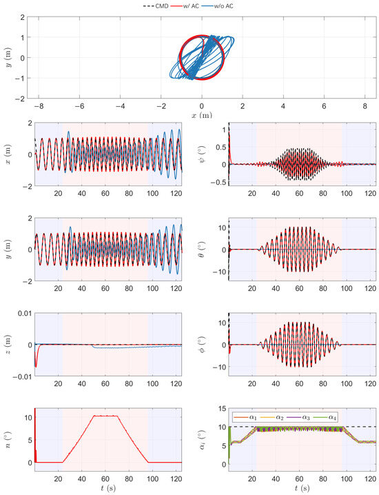
Figure 11.
Simulation results of the fully actuated quadrotor UAV in a high-maneuverability flight scenario.
During the low-speed phase, the rotor deflection angles remain below saturation, and the UAV operates in the fully actuated mode. Rotor tilting alone suffices to generate the necessary control forces for precise trajectory tracking while the attitude tracks the reference orientation.
As maneuverability increases with rising , the required lateral force eventually exceeds the capacity provided by rotor deflection alone. When reaches , the system transitions into the hybrid mode. At this point, the attitude compensation module becomes active, dynamically adjusting the attitude command to maintain tracking performance. The compensation angle n increases, enabling the UAV to redirect the thrust vector toward the desired force direction.
Without the attitude compensation strategy, rotor deflection saturation leads to unmitigated control input limits, resulting in large position tracking errors. In this case, the UAV cannot generate sufficient lateral force, and tracking performance degrades significantly, particularly during aggressive maneuvers.
In summary, this experiment confirms that the proposed control framework effectively maintains stable and accurate trajectory tracking across both fully actuated and hybrid modes in high-maneuverability scenarios. The attitude compensation strategy not only mitigates the limitations imposed by rotor deflection saturation but also ensures robust performance in dynamic and demanding flight tasks.
6. Flight Experiments
Flight experiments were conducted to validate the fully actuated capabilities of the UAV. These experiments were designed to showcase decoupled control of position and attitude. The tests covered attitude response and trajectory tracking.
6.1. Attitude Tracking
To evaluate the capability of the control system to decouple position and attitude, the first experiment commands the UAV to perform a pitch angle maneuver while maintaining a fixed spatial position. The UAV is initialized at the origin with zero velocity and attitude, and its position reference is held constant throughout the flight. At , the pitch angle command is ramped to , held steady for , and then returned to . No changes are made to the desired position or yaw angle, ensuring that only the pitch is perturbed.
The flight data shown in Figure 12 demonstrate the UAV’s stable position-holding behavior during the attitude maneuver. The actual position in all three axes remains nearly constant, and the position error remains within ± m despite the large angular excursion. This confirms that the system effectively decouples translational and rotational motion. The attitude response closely follows the commanded pitch angle , with fast transient behavior and negligible overshoot. The roll and yaw angles remain near zero, validating the isolation of the pitch channel. The attitude tracking error stays bounded within ±, indicating accurate and well-damped control.
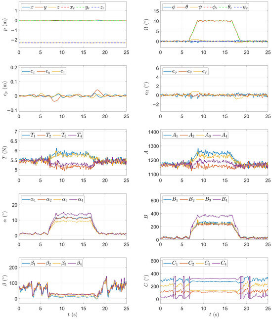
Figure 12.
Experiment result of pitch adjustment while maintaining a fixed position.
6.2. Trajectory Tracking
In this experiment, the quadrotor was tasked with tracking the “8” shape trajectory while maintaining a horizontal attitude in fully actuated mode. The goal of this experiment was to demonstrate the trajectory and attitude tracking performance. The experimental results, shown in Figure 13, illustrate the quadrotor’s trajectory tracking and attitude maintenance capabilities under the proposed control method. The reference trajectory is defined as
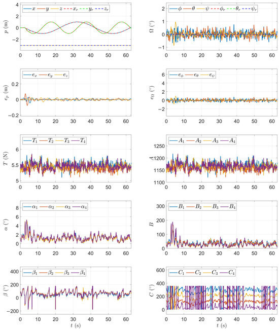
Figure 13.
Experimental result of trajectory tracking.
The UAV tracks the trajectory with high precision. The position components closely match their references and the position error remains within ± m for the entire 60 s flight. Despite the continuous motion, the UAV maintains a nearly level attitude and the attitude error remaining small. This confirms that the system can reject disturbances and internal dynamics while maintaining both orientation and trajectory tracking.
The results confirm that the fully actuated UAV, under the proposed control strategy, is capable of accurate trajectory tracking during dynamic flight without excessive actuator effort. The controller maintains stable and coordinated behavior, and the rotor modulation parameters exhibit regular patterns consistent with the vehicle’s motion. No saturation or instability occurs, validating the robustness and efficiency of the control law in nominal flight conditions.
7. Conclusions
This paper presented a fully actuated quadrotor UAV design featuring a swashplateless rotor mechanism, which enables independent control of position and orientation without relying on complex servo-driven tilting structures. By replacing conventional fixed-pitch rotors with swashplateless units, the proposed design achieves full actuation with minimal structural modifications, maintaining mechanical simplicity and lightweight characteristics. To accommodate the demands of different flight tasks, a decoupled control framework was developed. This framework employs nonlinear dynamic inversion (NDI) method to decouple position and attitude control into parallel structures. Extended state observers were integrated to estimate and compensate for lumped disturbances and model uncertainties, thereby enhancing the system’s robustness. Additionally, an attitude compensation strategy was introduced to address the force saturation problem caused by the maximum rotor deflection angle, allowing the commanded thrust to remain within the feasible set. This strategy enables seamless switching between fully actuated and underactuated modes. The effectiveness of the proposed design and control approach was validated through simulation and flight experiments.
Author Contributions
Conceptualization and methodology, Z.Z.; software, Z.Z. and H.J.; validation, Z.Z., H.J. and J.L.; writing—original draft preparation, Z.Z.; writing—review and editing, Z.Z., Z.W. and Y.L.; supervision, Y.L. and Z.W.; project administration, Y.L. and Z.W. All authors have read and agreed to the published version of the manuscript.
Funding
This research was supported by the Fundamental Research Funds for the Central Universities, the National Natural Science Foundation of China (Grant No. 62403385), and the Open Funding of National Key Laboratory of Digital and Agile Aircraft Design.
Data Availability Statement
Data are contained within the article.
Conflicts of Interest
The authors declare no conflicts of interest.
References
- Sun, G.; He, L.; Sun, Z.; Wu, Q.; Liang, S.; Li, J.; Niyato, D.; Leung, V.C.M. Joint task offloading and resource allocation in aerial-terrestrial UAV networks with edge and fog computing for post-disaster rescue. IEEE Trans. Mobile Comput. 2024, 23, 8582–8600. [Google Scholar] [CrossRef]
- Zhang, Z.; Li, Y.; Xu, J.; Wang, Z. Simultaneous search and tracking of non-cooperative mobile targets using multiple UAVs in uneven environments. Int. J. Aeronaut. Space Sci. 2024, 25, 1479–1493. [Google Scholar]
- Zhang, B.; Lin, X.; Zhu, Y.; Tian, J.; Zhu, Z. Enhancing multi-UAV reconnaissance and search through double critic DDPG with belief probability maps. IEEE Trans. Intell. Veh. 2024, 9, 3827–3842. [Google Scholar] [CrossRef]
- Zhang, Z.; Li, Y.; Gu, Z.; Wang, Z. Formation rotation and assignment: Avoiding obstacles in multi-robot scenarios. IEEE Robot. Autom. Lett. 2024, 9, 7015–7022. [Google Scholar] [CrossRef]
- Cohen, A.P.; Shaheen, S.A.; Farrar, E.M. Urban air mobility: History, ecosystem, market potential, and challenges. IEEE Trans. Intell. Transp. Syst. 2021, 22, 6074–6087. [Google Scholar] [CrossRef]
- Staub, N.; Bicego, D.; Sablé, Q.; Arellano, V.; Mishra, S.; Franchi, A. Towards a flying assistant paradigm: The OTHex. In Proceedings of the 2018 IEEE International Conference on Robotics and Automation (ICRA), Brisbane, Australia, 21–25 May 2018; pp. 6997–7002. [Google Scholar]
- Ryll, M.; Bicego, D.; Giurato, M.; Lovera, M.; Franchi, A. Fast-hex—A morphing hexarotor: Design, mechanical implementation, control and experimental validation. IEEE/ASME Trans. Mechatron. 2021, 27, 1244–1255. [Google Scholar] [CrossRef]
- Li, B.; Ma, L.; Wang, D.; Sun, Y. Driving and tilt-hovering—An agile and manoeuvrable aerial vehicle with tiltable rotors. IET Cyber-Syst. Robot. 2021, 3, 103–115. [Google Scholar] [CrossRef]
- Lv, Z.Y.; Wu, Y.; Zhao, Q.; Sun, X.M. Design and control of a novel coaxial tilt-rotor UAV. IEEE Trans. Ind. Electron. 2021, 69, 3810–3821. [Google Scholar] [CrossRef]
- Liu, K.; Ma, L.; Zhou, H.; Li, S. Structure Design and Control of a Novel Tilt-rotor Quadrotor with Thrust Vectoring. In Proceedings of the 2022 IEEE 17th Conference on Industrial Electronics and Applications (ICIEA), Chengdu, China, 16–19 December 2022; pp. 774–779. [Google Scholar]
- Odelga, M.; Stegagno, P.; Bülthoff, H.H. A fully actuated quadrotor UAV with a propeller tilting mechanism: Modeling and control. In Proceedings of the 2016 IEEE International Conference on Advanced Intelligent Mechatronics (AIM), Banff, AB, Canada, 12–15 July 2016; pp. 306–311. [Google Scholar]
- Yi, S.; Watanabe, K.; Nagai, I. Control of an over-actuated quadrotor manipulator based on backstepping integral sliding mode. In Proceedings of the 2021 International Conference on Advances in Computing, Communication, and Control (ICAC3), Mumbai, India, 3–4 December 2021; pp. 1–6. [Google Scholar]
- Li, Z.; Yang, Y.; Yu, X.; Liu, C.; Kaynak, O.; Gao, H. Fixed-Time Control of a Novel Thrust-Vectoring Aerial Manipulator via High-Order Fully Actuated System Approach. IEEE/ASME Trans. Mechatron. 2024, 30, 1084–1095. [Google Scholar] [CrossRef]
- Paulos, J.; Yim, M. Scalability of cyclic control without blade pitch actuators. In Proceedings of the 2018 AIAA Atmospheric Flight Mechanics Conference, Kissimmee, FL, USA, 8–12 January 2018; p. 0532. [Google Scholar]
- Paulos, J.; Yim, M. Cyclic blade pitch control without a swashplate for small helicopters. J. Guid. Control. Dyn. 2018, 41, 689–700. [Google Scholar] [CrossRef]
- Paulos, J.; Yim, M. An underactuated propeller for attitude control in micro air vehicles. In Proceedings of the 2013 IEEE/RSJ International Conference on Intelligent Robots and Systems, Tokyo, Japan, 3–7 November 2013; pp. 1374–1379. [Google Scholar]
- Paulos, J.; Yim, M. Flight performance of a swashplateless micro air vehicle. In Proceedings of the 2015 IEEE International Conference on Robotics and Automation (ICRA), Seattle, WA, USA, 26–30 May 2015; pp. 5284–5289. [Google Scholar]
- Paulos, J.; Caraher, B.; Yim, M. Emulating a fully actuated aerial vehicle using two actuators. In Proceedings of the 2018 IEEE International Conference on Robotics and Automation (ICRA), Brisbane, Australia, 21–25 May 2018; pp. 7011–7016. [Google Scholar]
- Chen, N.; Kong, F.; Xu, W.; Cai, Y.; Li, H.; He, D.; Qin, Y.; Zhang, F. A self-rotating, single-actuated UAV with extended sensor field of view for autonomous navigation. Sci. Robot. 2023, 8, eade4538. [Google Scholar] [CrossRef] [PubMed]
- Qin, Y.; Chen, N.; Cai, Y.; Xu, W.; Zhang, F. Gemini ii: Design, modeling, and control of a compact yet efficient servoless bi-copter. IEEE/ASME Trans. Mechatron. 2022, 27, 4304–4315. [Google Scholar] [CrossRef]
- Sunnysky. V4006 SUNNYSKY The Most Stable Power System. Available online: http://en.rcsunnysky.com/v-multi-rotorefficiencytype/1081.html (accessed on 29 April 2025).
- MagnTek. MT6835 Rev.1.3: 21-Bit High Accuracy Magnetic Angle Encoder IC. Available online: https://www.magntek.com.cn/upload/pdf/202407/MT6835_Rev.1.3.pdf (accessed on 29 April 2025).
- Chen, N.; Kong, F.; Li, H.; Liu, J.; Ye, Z.; Xu, W.; Zhu, F.; Lyu, X.; Zhang, F. Swashplateless-elevon Actuation for a Dual-rotor Tail-sitter VTOL UAV. In Proceedings of the 2023 IEEE/RSJ International Conference on Intelligent Robots and Systems (IROS), Detroit, MI, USA, 1–5 October 2023; pp. 6970–6976. [Google Scholar]
- CUAV. Nora+ Controller—CUAV. Available online: https://www.cuav.net/en/nora-plus-en/ (accessed on 29 April 2025).
- Raspberry Pi Ltd. Raspberry Pi 4 Model B. Available online: https://www.raspberrypi.com/products/raspberry-pi-4-model-b/ (accessed on 29 April 2025).
- Nokov. About Us—NOKOV Motion Capture. Available online: https://en.nokov.com/about/about-us.html (accessed on 29 April 2025).
- Murray, R.M.; Li, Z.; Sastry, S.S. A Mathematical Introduction to Robotic Manipulation; CRC Press: Boca Raton, FL, USA, 1994. [Google Scholar]
- Yang, X.; Huang, Y. Capabilities of extended state observer for estimating uncertainties. In Proceedings of the 2009 American Control Conference, St. Louis, MO, USA, 10–12 June 2009; pp. 3700–3705. [Google Scholar]
Disclaimer/Publisher’s Note: The statements, opinions and data contained in all publications are solely those of the individual author(s) and contributor(s) and not of MDPI and/or the editor(s). MDPI and/or the editor(s) disclaim responsibility for any injury to people or property resulting from any ideas, methods, instructions or products referred to in the content. |
© 2025 by the authors. Licensee MDPI, Basel, Switzerland. This article is an open access article distributed under the terms and conditions of the Creative Commons Attribution (CC BY) license (https://creativecommons.org/licenses/by/4.0/).