Article

Collision Avoidance and Formation Tracking Control for Heterogeneous UAV/USV Systems with Input Quantization

College of Navigation, Dalian Maritime University, Dalian 116026, China
*
Author to whom correspondence should be addressed.
Actuators 2025, 14(7), 309; https://doi.org/10.3390/act14070309
Submission received: 22 April 2025 / Revised: 18 June 2025 / Accepted: 19 June 2025 / Published: 23 June 2025
(This article belongs to the Special Issue Control System of Autonomous Surface Vehicle)

Abstract

This study addresses the heterogeneous formation control problem for cooperative unmanned aerial vehicles (UAVs) and unmanned surface vehicles (USVs) operating under input quantization constraints. A unified mathematical framework is developed to harmonize the distinct dynamic models of UAVs and USVs in the horizontal plane. The proposed control architecture adopts a hierarchical design, decomposing the system into kinematic and dynamic subsystems. At the kinematic level, an artificial potential field method is implemented to ensure collision avoidance between vehicles and obstacles. The dynamic subsystem incorporates neural network-based estimation to compensate for system uncertainties and unknown parameters. To address communication constraints, a linear quantization model is introduced for control input processing. Additionally, adaptive control laws are formulated in the vertical plane to achieve precise altitude tracking. The overall system stability is rigorously analyzed using input-to-state stability theory. Finally, numerical simulations demonstrate the effectiveness of the proposed control strategy in achieving coordinated formation control.

1. Introduction

With the rapid development of unmanned technology and automation control technology, the development of unmanned systems has made significant progress [1,2,3,4,5]. USVs have been widely used in marine engineering because of their advantages include small size, high flexibility, high speed, low cost, easy maneuverability, and no risk of casualties [6,7,8,9]. Compared with single USV, multi-USV has a greater improvement in fault tolerance and adaptive capability. Utilizing multi-USV collaboration for cluster control not only alleviates operator workload but also enhances the sustainability, scalability, and intelligence of oceanic operations [10,11,12,13]. However, the limited observation range of USVs brings certain challenges to target localization in maritime search and rescue operations [14]. To address this limitation, the integration of USVs and UAVs to form heterogeneous multi-agent systems has been shown to be reasonable and effective [15]. The construction of such a heterogeneous UAV/USV system not only effectively broadens the observation range of maritime communication of UAVs but also has important engineering significance.
There are now many research results for the problem of cooperative tracking control of UAVs and USVs [16,17,18,19,20,21,22]. Typical collaborative control methods include the leader-following method [23], the virtual structure method [24], and the graph theory-based method [25]. According to different formation control structures, it can be divided into distributed control [26], centralized control [27], and decentralized control [28]. According to the different control targets, it can be divided into formation target tracking [29], formation trajectory tracking [30,31,32], and formation path tracking [33]. Haitao Liu [34] investigates formation trajectory challenges in heterogeneous multi-agent systems facing external interference, model uncertainty, and input saturation. A distributed formation control strategy is presented for the UAV-USV heterogeneous multi-agent system, merging adaptive techniques and neural networks for optimal performance. Shaoshi Li [35] introduces a control scheme employing velocity estimation, featuring a distributed observer to estimate the reference velocity for each aircraft. The scheme also incorporates a distributed formation control rule based on estimation and azimuth measurement to achieve optimal formation. Dapeng Huang [36] designed a distributed model predictive control scheme to coordinate the UAVs-USVs system and carried out feasibility and stability analysis to ensure the formation of a satisfactory system. Yandong Li [37] employs a distributed optimal control approach to investigate cooperative formation challenges among heterogeneous multi-aircraft in both air and ground environments. Introducing optimal control theory into the formation control protocol, a distributed optimal formation control protocol is devised. It is worth noting that despite the contributions of the aforementioned academic works, the complex challenges posed by bandwidth constraints in maritime communications still need to be addressed.
At present, the quantitative problems have been considered in the practice of physical systems [38,39,40,41,42,43,44,45]. Fang Xiao [46] addresses the constraint of limited communication bandwidth by quantifying the transmitted information of the USVs through a uniform quantizer. Shixun Xiong [47] tackled the dynamic output feedback consensus control issue in leader-follower formations for linear heterogeneous multi-agent systems, integrating a dynamic quantizer. Bohao Zheng [48] develops an adaptive sliding mode control approach with a static adjustment method for quantized parameters to address the stabilization problem of uncertain systems using quantized output feedback. However, input quantification for heterogeneous UAV and USV formation control systems has hardly been considered in existing articles.
Collision avoidance plays a key role in navigation. As the operations of USVs and UAVs become more complex and collaborative, the development of robust collision avoidance algorithms is crucial for ensuring safe and efficient missions. For instance, Meryem Hamidaoui [49] provided a comprehensive survey of collision avoidance algorithms for autonomous vehicles, highlighting various approaches to achieve safe navigation in complex environments. Additionally, Sunan Huang [50] conducted an in-depth analysis of collision avoidance strategies for multiple UAVs. These studies offer valuable insights and references for designing effective collision avoidance control schemes. In this paper, the proposed control strategy not only achieves precise path tracking but also effectively addresses the obstacle avoidance problem through the introduction of an artificial potential field method, contributing novel solutions to the field of collision avoidance.
Based on the above problems, this paper designs an adaptive distributed heterogeneous UAV/USV collision avoidance formation control algorithm with input quantization. On the consistent model of the horizontal plane, the heterogeneous formation collision avoidance and tracking control systems are proposed hierarchically in terms of both kinematics and dynamics. At the kinematic level, an artificial potential field is introduced. At the dynamic level, the neural network estimates the effect of uncertain terms and unknown parameters. Moreover, adaptive controllers are designed on the vertical plane to track the desired altitude. Subsequently, the stability of the adaptive quantized distributed formation tracking control system is verified utilizing input-to-state stability theory. Finally, simulation results confirm the efficacy of the proposed control strategy.
In comparison with existing results [16,17,18,19,20,21,22,34,35,36,37,38,39,40,41,42,43,44,45,46,47,48], the main contributions of this paper can be summarized as follows:
(1)
By comparing with existing formation tracking control methods [16,17,18,19,20,21,22,34,35,36,37], this paper explores the complex domain of heterogeneous UAV and USV formation control combined with input quantization.
(2)
By comparing with previous studies [38,39,40,41,42,46,47,48] that addressed input quantization in formation control systems, this paper presents a linear time-varying model that describes the quantization process, eliminating the need for quantization parameter information and simplifying the process of achieving control input quantization.
(3)
By comparing with previous controller design methods [43,44], this paper considers bandwidth limitations in actual navigation and potential obstacles such as buoys and successfully integrates an improved artificial potential field into the kinematic guidance process, enabling agents in a formation to perform reasonable collision avoidance and obstacle avoidance maneuvers.

2. Problem Formulation

Consider the heterogeneous multi-agent systems (HMASs) consisting of one leader UAV and N follower USVs.
According to the Lagrange equation, the mathematical model of UAV motion is constructed in the geodetic coordinate system as [34]
p ¨ a x = ( cos ϕ sin θ cos ψ + sin ϕ sin ψ ) u p / m a d x p ˙ a x / m a + Γ a x , p ¨ a y = ( cos ϕ sin θ sin ψ + sin ϕ cos ψ ) u p / m a d y p ˙ a y / m a + Γ a y , p ¨ a z = ( cos θ cos ϕ ) u p / m a d z p ˙ a z / m a g + Γ a z ,
ϕ ¨ = θ ˙ ψ ˙ ( J a y J a z ) / J a x J a r / J a x θ ˙ d ¯ + τ ϕ / J a x d ϕ ϕ ˙ / J a x , θ ¨ = ϕ ˙ ψ ˙ ( J a z J a x ) / J a y J a r / J a y ϕ ˙ d ¯ + τ θ / J a y d θ θ ˙ / J a y , ψ ¨ = ϕ ˙ θ ˙ ( J a x J a y ) / J a z + τ ψ / J a z d ψ ψ ˙ / J a z .
where p ax , p ay , p a z T indicates the spatial location information of the UAV, ϕ , θ , ψ T indicates the attitude information of the UAV; u p is defined as the control thrust of the UAV; τ ϕ , τ θ , τ ψ T indicates the three control torques of the UAV; Define m a as the mass of the UAV, g indicates the gravitational acceleration; d ¯ indicates the overall residual rotor angle; d x , d y , d z denote the translational drag coefficients; d ϕ , d θ , d ψ denote the rotational drag coefficients; Define J a x , J a y , J a z as the moments of inertia; Define J a r as the inertia of the rotor; Γ a x , Γ a y , Γ a z indicate the external interference encountered by the UAV.
Assumption 1. 
Aerodynamic drag coefficients d x , d y , d z are unknown and bounded.
Assumption 2. 
The external interference Γ a x , Γ a y , Γ a z encountered by the UAV are bounded and satisfy Γ a x Γ ¯ a x , Γ a y Γ ¯ a y , Γ a z Γ ¯ a z , in which Γ ¯ a x , Γ ¯ a y , and Γ ¯ a z are positive constants.
Based on the above assumptions, considering external disturbances and parametric uncertainties, the upper bound of them is known. The three degrees of freedom model of UAV can be redefined as follows:
p ¨ a = g a u a + f a + Γ a .
where p a = p ax , p ay , p az T denotes the position of the UAV, g a = diag 1 / m a , 1 / m a , 1 / m a , f a = d x p ˙ a x / m a , d y p ˙ a y / m a , d z p ˙ a z / m a g T , Γ a = Γ a x , Γ a y , Γ a z T , u a = u a x , u a y , u a z T is defined as follows
u a x = cos ϕ sin θ cos ψ + sin ϕ sin ψ u p , u ay = cos ϕ sin θ sin ψ sin ϕ cos ψ u p , u a z = cos θ cos ϕ u p .
Consider the mathematical model of USV motion in the in the XY plane is defined as follows [40]
x ˙ s i = μ s i cos ψ s i v s i sin ψ s i , y ˙ s i = μ s i sin ψ s i + v s i cos ψ s i , ψ ˙ s i = r s i .
μ ˙ s i = f μ s i ( α i ) + ( τ μ s i f + w μ s i ) / m μ s i , v ˙ s i = f v s i ( α i ) + w v s i / m v s i , r ˙ s i = f r s i ( α i ) + ( τ r s i f + w r s i ) / m r s i .
and
f μ s i α i = 1 m μ s i m v s i v s i r s i d μ s i μ s i d μ s i 1 μ s i μ s i , f v s i α i = 1 m v s i m μ s i μ s i r s i d v s i v s i d v s i 1 v s i v s i , f r s i ( α i ) = 1 m r s i ( ( m μ s i m v s i ) μ s i v s i d r s i 1 | r s i | r s i d r s i r s i ) .
where x s i , y s i T is defined as the position information of the i-th USV; ψ s i is defined as the yaw angle of the i-th USV; α i = μ s i , v s i , r s i T are the surge, sway and yaw velocity, respectively, m μ s i , m v s i , m r s i are the inertial mass; f μ s i α i , f v s i α i , f r s i α i are the nonlinear unknown functions consisting of the unmodeled hydrodynamics and Coriolis forces; τ μ s i f and τ r s i f are the surge force and the yaw moment. w μ s i , w v s i , w r s i are the bounded disturbances caused by waves, wind, and ocean currents.
To deal with the underdriven USV motion model described in (5) and (6), we consider the idea of the hand-position method to deal with it. Defining the front point of the USV as the hand-position, it can be expressed as [51,52]
p s i x = x s i + L s i cos ψ s i , p s i y = y s i + L s i sin ψ s i .
where L s i is the distance between the actual position x s i , y s i T and the new defined hand point p s i x , p s i y , which is shown in Figure 1.
By taking the second derivative of (8), it shows that
p ¨ s i x = μ ˙ s i cos ψ s i v ˙ s i + L s i r ˙ s i sin ψ s i μ s i r s i sin ψ s i v s i r s i + L s i r s i 2 cos ψ s i , p ¨ s i y = μ ˙ s i sin ψ s i v ˙ s i + L s i r ˙ s i cos ψ s i + μ s i r s i cos ψ s i v s i r s i + L s i r s i 2 sin ψ s i ,
substituting (7) into (9) yields that
p ¨ s i x = f s i x ( β i ) + cos ψ s i / m μ s i τ μ s i f L s i sin ψ s i / m r s i τ r s i f + w d i x , p ¨ s i y = f s i y ( β i ) + sin ψ s i / m μ s i τ μ s i f + L s i cos ψ s i / m r s i τ r s i f + w d i y .
where
f s i x ( β i ) = f μ s i ( α i ) cos ψ s i f v s i ( α i ) + L s i f r s i ( α i ) sin ψ s i μ s i r s i sin ψ s i v s i r s i + L s i r s i 2 cos ψ s i , f s i y ( β i ) = f μ s i ( α i ) sin ψ s i + f v s i ( α i ) + L s i f r s i ( α i ) cos ψ s i + μ s i r s i cos ψ s i v s i r s i + L s i r s i 2 sin ψ s i ,
w d i x ( β i ) = w v s i / m μ s i + L s i w r s i / m r s i sin ψ s i + w μ s i / m μ s i cos ψ s i , w d i y ( β i ) = w v s i / m μ s i + L s i w r s i / m r s i cos ψ s i + w μ s i / m μ s i sin ψ s i .
with β i = μ s i , v s i , r s i , ψ s i .
Based on (10), the dynamics model of the i-th USV can be described as [53]
p ¨ s i = f s i x y + Ω s i ψ s i ω s i u s i + w d i x y .
where p si = p six , p siy T is the position of the i-th USV, and f sixy = f six , f siy T , Ω s i ψ s i = cos ψ s i , sin ψ s i ; sin ψ s i , cos ψ s i , u s i = τ μ i , τ r i T , ω s i = diag 1 / m μ s i , L s i / m r s i , w d i x y = w d i x , w d i y T .
To ensure uniformity between the USV model and the UAV model, (13) is extended and can be converted to
p ¨ s i x p ¨ s i y = cos ψ s i / m μ s i 0 0 L s i cos ψ s i / m r s i τ μ i τ r i + w d i x w d i y + f s i x L s i sin ψ s i / m r s i τ r i f s i y + sin ψ s i / m μ s i τ μ i .
Combining (3) and (14), the unified model of the HMASs in the two-dimensional horizontal plane can be obtained
x ˙ i 1 = x i 2 , x ˙ i 2 = F x i + G x i u x i + Γ x i .
when Equation (15) represents the UAV model x i 1 = p x i p y i = x a 1 R 2 , x i 2 = U i V i = x a 2 R 2 is defined as the position and speed information of the UAV in the X Y plane, F x i = f a x y is defined as unknown functions, G x i = g a x y is defined as coefficient matrix, Γ x i = Γ a x y indicate the external interference encountered by the UAV, u x i = u a x y is defined as coefficient matrix control input signal.
when Equation (15) represents the USV model x i 1 = p x i p y i = x s i 1 R 2 , x i 2 = U i V i = x s i 2 R 2 is the position and velocity of the i-th USV, F x i = F s i = f s i x L s i sin ψ s i m r s i τ r i f s i y + sin ψ s i m μ s i τ μ i is defined as unknown functions, G x i = G s i = d i a g [ cos ψ s i m μ s i , L s i cos ψ s i m r s i ] is defined as a coefficient matrix, Γ x i = Γ d i x y is the bounded disturbances, u x i = u s i is defined as a coefficient matrix control input signal.
Similarly, the mathematical model of a UAV in the vertical plane can be constructed as
p ˙ a z = v a z , v ˙ a z = f a z + u a z / m a + Γ a z = F a z + G a z u a z + Γ a z .
where p a z is the altitude of the UAV; v a z is defined as the speed of the UAV in the Z axis, F a z = d z p ˙ a z d z p ˙ a z m a m a g , G a z = 1 / m a .
The quantization technique converts an initial continuous signal into a segmented and constant signal. The input quantized HMASs model can be expressed as follows using a mean quantizer based on (3) followed by (15)
U ˙ s i V ˙ s i = cos ψ s i / m μ s i 0 0 L s i cos ψ s i / m r s i Q ( τ μ i ) Q ( τ r i ) + w d i x w d i y + f s i x L s i sin ψ s i / m r s i Q ( τ r i ) f s i y + sin ψ s i / m μ s i Q ( τ μ i ) ,
U ˙ a V ˙ a = d x p ˙ a x / m a d y p ˙ a y / m a + m a 1 0 0 m a 1 Q ( u a x ) Q ( u a y ) + Γ a x Γ a y .
where the functions Q ( . ) are the quantized values of the control inputs.
Combining (15), (17) and (18), the HMASs model with input quantization is represented as
x ˙ i 1 = x i 2 , x ˙ i 2 = F x i + G x i Q ( u x i ) + Γ x i .
Based on (19), the HMAS model dynamics model considering input quantization is
U ˙ i V ˙ i = F i + G i Q τ i + Γ i ,
where F i = F i U , F i V T , F i U , F i V are defined as unknown functions. Q τ i = Q ( τ i U ) , Q ( τ i V ) T , G i = d i a g [ G i U , G i V ] , Γ i = Γ i U , Γ i V T , τ i = u x i , Q ( τ i U ) = k i U r o u n d ( τ i U / k i U ) , Q ( τ i V ) = k i V r o u n d ( τ i V / k i V ) .
The uniform quantization has the characteristic of easy realization. It can be expressed as follows [54,55]
Q ( τ i U ) = k i U r o u n d ( τ i U k i U ) ,
Q ( τ i V ) = k i V r o u n d ( τ i V k i V ) ,
where k i U , k i V denotes the quantized index.
During the quantization process, quantization errors will be generated, and the performance of the control system could be reduced. A continuous and differentiable time-varying reference trajectory is defined
p 0 ( t ) = [ x 0 ( t ) , y 0 ( t ) ] T R 2 .
Let G = { V , E } represent the multi-USV and UAV communication topology diagram, where V = { n 0 , n 1 , , n N } is the set of all nodes combined, denotes N agents in formation; E = { ( i , j ) V × V } is a set of all edges. Define A = a i j R N × N is the adjacency matrix, when ( n i , n j ) E , a i j = 1 , if not a i j = 0 .
In this paper, a distributed controller is considered for each unmanned agent to ensure that each USV and UAV can track the expected time-varying trajectory and ensure [54]
lim t p i ( t ) p i d ( t ) p 0 ( t ) l i 0 ,
where l i 0 is a positive constant, p i d ( t ) R 2 is the position deviation relative to the parameterized path. p i ( t ) = [ x i ( t ) , y i ( t ) ] T R 2 defines the target position of each follower agent concerning the virtual leader’s trajectory p 0 ( t ) .
Assumption 3. 
The following agents in the formation have the same potential energy [56].
Based on Assumption 3, the potential function of the collision avoidance repulsive field between the following unmanned vessels in the formation is expressed as
ϕ i j c ( p i j ) = min 0 , p i j 2 R ¯ 2 p i j 2 R ̲ 2 2 ,
where p i j = x i x j 2 + y i y j 2 denotes the Euclidean distance between two agents in the formation. R ¯ > 0 , R ̲ > 0 , R ¯ > R ̲ are the upper and lower boundaries of the collision avoidance region. If the distance between two agents satisfies R ̲ < p i j < R ¯ , the collision avoidance potential function ϕ i j c ( p i j ) is greater than zero and the potential function is valid in the additional control inputs.
Then the collision avoidance repulsion function is [57,58]
ϕ i j c p i = 4 R ¯ 2 R ̲ 2 p i j 2 R ¯ 2 p i j 2 R ̲ 2 3 p i j , R ̲ < p i j < R ¯ , 0 2 , p i j > R ¯ .
where 0 2 is a 2 × 2 zero vector matrix.
The obstacle avoidance potential function between each unmanned vessel and the obstacle is expressed as [59]
ϕ i k o ( p i j ) = min 0 , p i k 2 R 0 2 ¯ p i k 2 R 0 2 ̲ 2 ,
where p i k = x i x k 2 + y i y k 2 denotes the Euclidean distance from the agent to the obstacle. R o ¯ > 0 , R 0 ̲ > 0 , R o ¯ > R 0 ̲ are the upper and lower boundaries of the collision avoidance area. If the distance between two agents satisfies R 0 ̲ < p i k < R o ¯ , the collision avoidance potential function ϕ i k o ( p i k ) is greater than zero and the potential function is valid for additional control inputs.
Then, the obstacle avoidance repulsion function is
ϕ i k 0 p i = 4 R 0 2 ¯ R 0 2 ̲ p i k 2 R 0 2 ¯ p i k 2 R 0 2 ̲ 3 p i k , R 0 ̲ < p i k < R 0 ¯ , 0 2 , p i k > R 0 ¯ .
To avoid collisions between unmanned vessels and between unmanned vessels and obstacles, it is also necessary to satisfy p i ( t ) p j ( t ) R ̲ and p i ( t ) p k ( t ) R o ̲ .

3. Controller Design

In this section, the controller design is divided into two parts: kinematics and dynamics. The trajectory tracking error signals and the underlying control input signals of the HMASs model are designed separately to track time-varying trajectories by introducing the artificial potential field theory.

3.1. Kinematic Controller Design

The continuous and differentiable time-varying reference trajectory is represented by p 0 ( t ) = [ x 0 ( t ) , y 0 ( t ) ] T R 2 .
Define the following heterogeneous agents tracking error
z i = j = 1 N a i j ( p i p j p i j d ) + a i 0 ( p i p 0 p i d ) ,
where p i j d = p i d p j d . Differentiating (27) gives
z ˙ i = j = 1 N a i j ( p i ˙ p j ˙ p i j d ˙ ) + a i 0 ( p i ˙ p 0 ˙ p ˙ i d ) = j = 1 N a i j ( [ x i ˙ , y i ˙ ] T [ x j ˙ , y j ˙ ] T p ˙ i j d ) + a i 0 ( [ x i ˙ , y i ˙ ] T p 0 ˙ p i d ˙ ) = j = 1 N a i j { U i , V i T [ U j , V j ] T p ˙ i j d } + a i 0 U i , V i T a i 0 p ˙ 0 a i 0 p ˙ i d ,
then (28) can be converted to
z ˙ i = d i U i , V i T a i 0 p ˙ 0 + ϱ i .
where d i = j = 0 N a i j , ϱ i = j = 1 N a i j p ˙ j j = 0 N a i j p ˙ i j d .
Assumption 4. 
Since the velocity and acceleration of HMASs are both upper bound, the unknown term ϱ i is assumed to satisfy ϱ ˙ i ϱ , where ϱ is a positive constant. The Extended State Observer can be used to observe the unknown term ϱ i [60].
Design the Extended State Observer(ESO) as follows:
z ^ ˙ i = ϑ i + ϱ ^ i k i 1 z ˜ i , ϱ ^ ˙ i = k i 2 z ˜ i .
where z ˜ i = z ^ i z i is defined as the ESO estimation error and ϑ i = d i U j , V j T a i 0 p ˙ 0 . Based on (29) and (30) it can be found that
z ˜ ˙ i = ϱ ˜ i k i 1 z ˜ i , ϱ ˜ ˙ i = k i 2 z ˜ i ϱ ˙ i .
where ϱ ˜ ˙ i = ϱ ^ ˙ i ϱ ˙ i is defined as the ESO estimation error of the unknown term. Equation (31) can be rewritten into
E ˜ ˙ i 1 = A i E ˜ i 1 + B i ,
where E ˜ i 1 = [ z ˜ i , ϱ ˜ i ] T , and
A i = k i 1 1 k i 2 0 , B i = 0 2 ϱ ˙ i .
Define q i = q i x q i y = z i + z i f , and
z i f = j = 1 N δ ϕ i j c δ p i + k = 1 N δ ϕ i k o δ p i .
where ϕ i j c and ϕ i k o are the artificial potential field potential functions defined in (23) and (25).
To attain dynamic stratigraphic control while ensuring path orientation with collision avoidance, and based on (29), the subsequent distributed kinematic guidance law can be devised as follows:
U i c V i c = d i 1 [ K i z i + a i 0 p ^ ˙ 0 ϱ ^ i ] = d i 1 [ K i q i Π i + a i 0 p ^ ˙ 0 + j = 1 N a i j p j ^ ˙ + j = 0 N a i j p ^ ˙ i j d ] = d i 1 [ K i q i Π i + j = 0 N a i j p j ^ ˙ + j = 0 N a i j p ^ ˙ i j d ] .
where K i = d i a g [ k i x , k i y ] R 2 , Π i = q i 2 + ε i 2 and ε i are positive constant.
Substituting (35) into (29), taking into account an artificial potential field, the kinematic trajectory tracking error can be obtained as follows:
z ˙ i = K i q i Π i + j = 0 N a i j p j ˜ ˙ + j = 0 N a i j p ˜ ˙ i j d .
where p i j d = p i d p j d .

3.2. Dynamic Controller Design

For the dynamics subsystem, a neural network is introduced to achieve the approximation of the uncertainty terms and unknown parameters of the system model. Stable tracking of the kinematic guidance law is achieved under the assumption that the quantization parameters are unknown by employing a linear model to describe the input quantization process.
According to (35), the control objectives of the dynamical subsystem are [54]
lim t e i U = U i U i c δ 1 , lim t e i V = V i V i c δ 2 .
where δ 1 , δ 2 are small positive constants.
Letting Q ( τ i U ) = q 1 i U ( t ) τ i U + q 2 i U ( t ) , Q ( τ i V ) = q 1 i V ( t ) τ i V + q 2 i V ( t ) , and
q 1 i U ( t ) = Q τ i U ( t ) τ i U ( t ) τ i U ( t ) 𝚥 1 τ i U ( t ) < 𝚥 , q 1 i V ( t ) = Q τ i V ( t ) τ i V ( t ) τ i V ( t ) 𝚥 1 τ i V ( t ) < 𝚥 , q 2 i U ( t ) = 0 τ i U ( t ) 𝚥 Q τ i U ( t ) τ i U ( t ) τ i U ( t ) < 𝚥 , q 2 i V ( t ) = 0 τ i V ( t ) 𝚥 Q τ i V ( t ) τ i V ( t ) τ i V ( t ) < 𝚥 ,
where q 1 i U ( t ) , q 1 i V ( t ) are unknown. In order to describe the quantization process using a linear model, a constant j is introduced. Since the quantization process does not change the positive and negative values of the signal, it can be seen that q 1 i U ( t ) > 0 , q 1 i V ( t ) > 0 from (38). If τ i U ( t ) < 𝚥 , τ i V ( t ) < 𝚥 , then Q ( τ i U ( t ) ) , Q ( τ i V ( t ) ) are bounded, it follows that q 2 i U ( t ) , q 2 i v ( t ) are also bounded, and satisfy q 2 i U ( t ) q ¯ 2 i U , q 2 i V ( t ) q ¯ 2 i V .
Define the two sliding mold surfaces as follows [54]
s i U = c i U 0 t e i U d t + e i U ( t ) , s i V = c i V 0 t e i V d t + e i V ( t ) ,
where c i U > 0 and c i V > 0 . The time derivative of (39) shows that
s ˙ i U = c i U e i U + e ˙ i U = G i U Q ( τ i U ) + Γ i U + F i U U ˙ i d + c i U e i U = G i U q 1 i U ( t ) τ i U + G i U q 2 i U ( t ) + Γ i U + F i U U ˙ i d + c i U e i U ,
and
s ˙ i V = c i V e i V + e ˙ i V = G i V Q ( τ i V ) + Γ i V + F i V V ˙ i d + c i V e i V = G i V q 1 i V ( t ) τ i V + G i V q 2 i V ( t ) + Γ i V + F i V V ˙ i d + c i V e i V .
Define d i U ( X ) = Γ i U + F i U , d i V ( X ) = Γ i V + F i V , (40) and (41) can be obtained that
s i U s ˙ i U s i U + 1 2 G i U s i U + d i U ( X ) + c i U e i U U ˙ i d + s i U G i U q 1 i U τ i U + 1 2 G i U q ¯ 2 i U 2 ,
s i V s ˙ i V s i V + 1 2 G i V s i V + d i V ( X ) + c i U e i V V ˙ i d + s i V G i V q 1 i V τ i V + 1 2 G i V q ¯ 2 i V 2 .
Since d i U ( X ) , d i V ( X ) are unknown terms, the following neural network is designed as follows:
d i U ( X ) = W i U T h i U ( X ) + ε i U , d i V ( X ) = W i V T h i V ( X ) + ε i V .
where W i U T , W i V T are the ideal weights of the neural network, ε i U , ε i V are the approximation error of the neural network, satisfying ε i U ε N , ε i V ε N , h i U ( X ) = g ( X c i j 2 / b i 2 ) , h i V ( X ) = g ( X c i j 2 / b i 2 ) are Gaussian functions.
Let d ^ i U ( X ) , d ^ i V ( X ) be the estimate of d i U ( X ) , d i V ( X ) and
d ^ i U ( X ) = W ^ i U T h i U ( X ) , d ^ i V ( X ) = W ^ i V T h i V ( X ) ,
where W ^ i U and W ^ i V are the estimate of the ideal weight W i U and W i V .
Define
κ i U = l i U s i U + η i U sgn s i U + 1 2 G i U s i U + d ^ i U ( X ) + c i U e i U U ˙ i d , κ i V = l i V s i V + η i V sgn s i V + 1 2 G i V s i V + d ^ i V ( X ) + c i V e i V V ˙ i d .
where l i U , l i V , η i U , η i V , η d are positive constants. η i U ε i U + η d , η i V ε i V + η d .
This leads to
s i U s ˙ i U l i U s i U 2 η i U s i U + s i U κ i U + 1 2 G i U q ¯ 2 i U 2 + s i U W ˜ i U T ( X ) h i U ( X ) + s i U G i U q 1 i U τ i U , s i V s ˙ i V l i V s i V 2 η i V s i V + s i V κ i V + 1 2 G i V q ¯ 2 i V 2 + s i V W ˜ i V T ( X ) h i V ( X ) + s i V G i V q 1 i V τ i V .
The time-varying unknown term q 1 i U ( t ) and q 1 i V ( t ) are estimated using an adaptive estimation design adaptive law. Defining time-varying gain μ i U = 1 / q 1 i U min , μ i V = 1 / q 1 i V min as the lower bound for q 1 i U ( t ) , q 1 i V ( t ) .
The dynamic controllers and adaptive laws are designed as follows [54]
τ i U = G i U 1 s i U μ ^ i U 2 κ i U 2 s i U μ ^ i U κ i U + ρ i U , τ i V = G i V 1 s i V μ ^ i V 2 κ i V 2 s i V μ ^ i V κ i V + ρ i V ,
μ ^ ˙ i U = γ 1 s i U κ i U γ 1 ς i U μ ^ i U , μ ^ ˙ i V = γ 2 s i V κ i V γ 2 ς i V μ ^ i V ,
W ^ ˙ i U = γ 3 s i U h i U ( X ) , W ^ ˙ i V = γ 4 s i V h i V ( X ) ,
where ρ i U , ρ i V , γ 1 , γ 2 , γ 3 , γ 4 , ς i U , ς i V are positive constants.
The error subsystem generated by z i , s i U , s i V , μ ˜ i U , μ ˜ i U , W ˜ i U , W ˜ i V is as follows:
z ˙ i = K i q i Π i + j = 0 N a i j p j ˜ ˙ + j = 0 N a i j p ˜ ˙ i j d , s ˙ i U = c i U e i U + e ˙ i U , s ˙ i V = c i V e i V + e ˙ i V , μ ˜ ˙ i U = μ ^ ˙ i U μ ˙ i U = γ 1 s i U κ i U γ 1 ς i U μ ^ i U , μ ˜ ˙ i V = μ ^ ˙ i V μ ˙ i V = γ 2 s i V κ i V γ 2 ς i V μ ^ i V , W ˜ ˙ i U = W ˙ i U W ^ ˙ i U = γ 3 s i U h i U ( X ) κ i U W ˜ i U , W ˜ ˙ i V = W ˙ i V W ^ ˙ i V = γ 4 s i V h i V ( X ) κ i V W ˜ i V .

3.3. Altitude Controller Design of UAV

Consider the following UAV altitude tracking error in the vertical plane
e a z p = p a z p a z d , e a z v = v a z v a z d ,
where p a z d is defined as the desired position information and v a z d is defined as the desired velocity information.
Consider the following inputs and adaptive laws [61]
u a z = G ^ a z 1 σ z e ζ e ζ κ ^ 11 h T h 2 ς 1 2 e ζ κ ^ 12 2 ς 2 2 + v ˙ a z d k ζ e a z v , κ ^ ˙ 11 = l 11 k 11 κ ^ 11 + e ζ T e ζ h T h 2 ς 1 2 , κ ^ ˙ 12 = l 12 k 12 κ ^ 12 + e ζ T e ζ 2 ς 2 2 , G ^ ˙ a z = Pr o j G a z , G ¯ a z { S } = 0 , if G ^ a z = G ¯ a z , S 0 or G ^ a z = G a z , S 0 , S , otherwise .
where S = ι 13 ( k 13 G ^ a z + e ζ u a z ) , e ζ = e a z v ζ z , the virtual control signal is designed to be ζ z = k ζ e a z p , G ¯ a z and G a z are the lower and upper bounds of G a z .   k 11 ,   k 12 ,   k 13 ,   ρ z ,   l 11 ,   l 12 ,   l 13 ,   k ζ ,   ς 1 ,   ς 2 are positive constants to be designed.

4. Stability Analysis

4.1. Kinematic Observer Stability

Lemma 1. 
System (32) can be viewed as a system with states z ˜ i and ϱ ˜ i and input ϱ ˙ i , then the system is input-to-state stable.
Proof. 
Consider the following Lyapunov function
V ˙ 1 = i = 1 N E ˜ i 1 T P i E ˜ i 1 ,
where P i is a positive definite matrix and is satisfied [54]
A i T P i + P i T A i I .
Differentiating of (54) gives
V ˙ 1 i = 1 N { E i 1 T E i 1 + E i 1 T P i B i ϱ ˙ i } ,
Because
E i 1 P i B i ϱ ˙ i θ ¯ i 1 ,
then
V ˙ 1 i = 1 N ( 1 θ ¯ i 1 ) E i 1 2 .
where 0 < θ ¯ i 1 < 1 , system (32) is input-to-state stable [62], and
E i 1 ( t ) λ max P i λ min P i max E i 1 t 0 e ϰ i 1 t t 0 , P i B i ϱ θ ¯ i 1 , t t 0 .
where ϰ i 1 = 1 θ ¯ i 1 / λ max P i . □

4.2. Cascade System Stability

Lemma 2. 
The error system can be viewed as a system with input D i U , D i V , ϱ ˜ i and state s i U , s i V , μ ˜ i U , μ ˜ i V , z i , which is input-to-state stable.
Proof. 
Consider the following Lyapunov function
V 4 = i = 1 N { 1 2 s i U 2 + 1 2 γ 1 μ i U μ ˜ i U 2 + 1 2 s i V 2 + 1 2 γ 2 μ i V μ ˜ i V 2 + 1 2 z i T z i + 1 2 γ 3 W ˜ i U T W ˜ i U + 1 2 γ 4 W ˜ i V T W ˜ i V + d i j = 1 N ϕ i j c + d i k = 1 N ϕ i k o } .
where μ ˜ i U = μ ^ i U μ i U > 0 , μ ˜ i V = μ ^ i V μ i V > 0 . Differentiating of (60) yields
V ˙ 4 = i = 1 N { s i U s ˙ i U + 1 γ 1 μ i U μ ˜ i U μ ^ ˙ i U + s i V s ˙ i V + 1 γ 2 μ i V μ ˜ i V μ ^ ˙ i V + z i T z ˙ i     + 1 2 γ 3 W ˜ i U T W ˜ i U + 1 2 γ 4 W ˜ i V T W ˜ i V + d i z i f T p ˙ i } ,
Substituting (47), (48), (49) and (50) into (61) yields
V ˙ 4 i = 1 N { l i U s i U 2 η i U s i U + 1 2 G i U q ¯ 2 i U 2 + 1 μ i U ρ i U 1 μ i U μ ˜ i U ς i U μ ^ i U l i V s i V 2 η i V s i V + 1 2 G i V q ¯ 2 i V 2 + 1 μ i V ρ i V 1 μ i V μ ˜ i V ς i V μ ^ i V k i U W ˜ i U T W ˜ i U k i V W ˜ i V T W ˜ i V + z i T z ˙ i + d i z i f T p ˙ i } ,
It is worth noting that
μ ˜ i U μ ^ i U 1 2 μ ˜ i U 2 + 1 2 μ i U 2 , μ ˜ i V μ ^ i V 1 2 μ ˜ i V 2 + 1 2 μ i V 2 ,
Convert (62) to
V ˙ 4 i = 1 N { l i U s i U 2 η i U s i U + 1 2 G i U q ¯ 2 i U 2 + 1 μ i U ρ i U 1 2 μ i U ς i U μ ˜ i U 2 + 1 2 ς i U μ i U l i V s i V 2 η i V s i V + 1 2 G i V q ¯ 2 i V 2 + 1 μ i V ρ i V 1 2 μ i V ς i V μ ˜ i V 2 + 1 2 ς i V μ i V k i U W ˜ i U T W ˜ i U k i V W ˜ i V T W ˜ i V + z i T z ˙ i + d i z i f T p ˙ i } ,
Define D i U = G i U q ¯ 2 i U 2 / 2 + ρ i U / μ i U + ς i U μ i U / 2 , D i V = G i V q ¯ 2 i V 2 / 2 + ρ i V / μ i V + ς i V μ i V / 2 . Convert (64) to
V ˙ 4 i = 1 N { l i U s i U 2 η i U s i U 1 2 μ i U ς i U μ ˜ i U 2 + D i U l i V s i V 2 η i V s i V 1 2 μ i V ς i V μ ˜ i V 2 + D i V k i U W ˜ i U T W ˜ i U k i V W ˜ i V T W ˜ i V + z i T z ˙ i + d i z i f T p ˙ i } .
Bringing (36) into (65) gives
V ˙ 4 i = 1 N { l i U s i U 2 l i V s i V 2 1 2 μ i U ς i U μ ˜ i U 2 1 2 μ i V ς i V μ ˜ i V 2 + D i U + D i V k i U W ˜ i U T W ˜ i U k i V W ˜ i V T W ˜ i V q i T K i q i + z i f T v ¯ i + q i T v } ,
where v ¯ i = j = 0 N a i j p ˙ j + j = 0 N a i j p ˙ i j d , v i = j = 0 N a i j p ˜ ˙ j + j = 0 N a i j p ˜ ˙ i j d . Equation (66) can be rewritten into
V ˙ 4 i = 1 N { l i U s i U 2 l i V s i V 2 1 2 μ i U ς i U μ ˜ i U 2 1 2 μ i V ς i V μ ˜ i V 2 + D i U + D i V k i U W ˜ i U 2 k i V W ˜ i V 2 λ min K i q i 2 + z i f T v ¯ i + q i T v i } .
Remark 1. 
The stability analysis is structured into two steps. Initially, we assess the stability of the closed-loop system within the collision avoidance region. Subsequently, we extend the analysis outside the collision avoidance region following the same reasoning process.
Define q = [ q 1 T , q 2 T , , q N T ] T , z = [ z 1 T , z 2 T , , z N T ] T , s U = [ s 1 U , s 2 U , , s N U ] T , s V = [ s 1 V , s 2 V , , s N V ] T , ћ 4 = min i = 1 , , N [ l i U , l i V , ς i U / 2 μ i U , ς i V / 2 μ i V , λ min ( K i ) , k i U , k i V ] , μ ˜ U = [ μ ˜ 1 U , μ ˜ 2 U , , μ ˜ N U ] T , μ ˜ V = [ μ ˜ 1 V , μ ˜ 2 V , , μ ˜ N V ] T , W ˜ U = [ W ˜ 1 U , W ˜ 2 U , , W ˜ N U ] T , W ˜ V = [ W ˜ 1 V , W ˜ 2 V , , W ˜ N V ] T . When in the collision avoidance area, (67) can be written as
V ˙ 4 i = 1 N { l i U s i U 2 l i V s i V 2 1 2 μ i U ς i U μ ˜ i U 2 1 2 μ i V ς i V μ ˜ i V 2 + D i U + D i V k i U W ˜ i U 2 k i V W ˜ i V 2 λ min K i q i 2 + 1 2 z i f T 2 + 1 2 v ¯ i 2 + 1 2 q i T 2 + 1 2 v i 2 } .
Define E 4 = [ s U , s V , μ ˜ U , μ ˜ V , q , W ˜ U , W ˜ V ] , M = v ¯ i 2 + z i f T 2 + q i T 2 + v i 2 , which gives
V ˙ 4 ( 1 θ ¯ 4 ) ћ 4 E 4 2 θ ¯ 4 ћ 4 E 4 2 + i = 1 N ( D i U + D i V + M + 1 2 E i 2 2 ) .
It can be noted that
E 4 i = 1 N 2 D i U + 2 D i V + M + E i 2 2 2 θ ¯ 4 ћ 4 ,
then
V ˙ 4 1 θ ¯ 4 ћ 4 E 4 2 .
where 0 < θ ¯ 4 < 1 . Thus, error system (51) is input-to-state stable and
E 4 ( t ) λ max P c λ min P c max E 4 t 0 e ϱ 4 t t 0 , i = 1 N 2 D i U + 2 D i V + M + E i 2 2 2 θ ¯ 4 ћ 4 , t t 0 .
where ϱ 4 = 2 ћ 4 1 θ ¯ 4 / λ max P c , and
P c = diag 1 , 1 2 γ 1 μ 1 U , , 1 2 γ 1 μ N U , 1 2 γ 2 μ 1 V , , 1 2 γ 2 μ N V .
Theorem 1. 
Consider in this paper a closed-loop system consisting of (19),(35), (48), and (49), where the cascade is input-to-state stable and the distributed formation error is uniformly eventually bounded.
Proof. 
Based on the stability theory of cascade systems, combining Lemma 1 with Lemma 2 yields that the cascade system composed of (32) and (51) is input-to-state stable and E 4 ( t ) is bounded by
E 4 ( t ) λ max P c λ min P c i = 1 N 2 D i U + 2 D i V + M 2 θ ¯ 4 ћ 4 + Q i P i 2 d ( X ) 2 2 θ ¯ 4 ћ 4 θ ¯ i 2 2 .
when the agent is outside the range of collision avoidance, due to ϕ i k 0 p i = 0 , therefore q i = z ¯ i . The size of the z i f T v ¯ i term in the above stability proof process is 0. Using the same argumentation process, the same conclusion can be obtained that the closed-loop system is still satisfactorily input-to-state stable. □

4.3. Vertical Plane Stability

Theorem 2. 
Assume that v a z d p ˙ a z d = 0 holds, the control scheme of formation tracking and the adaptive law is designed as (53), then the UAV can achieve tracking of the desired altitude signal, and the tracking error e a z p is uniformly ultimately bounded.
Proof. 
The time derivative of (52) can be gained as follows
e ˙ a z p = e a z v , e ˙ a z v = F a z + G a z u a z + Γ a z v ˙ a z d .
In system (75), regarding e a z v as the virtual control input. Design the virtual control signal ζ z = k ζ e a z p to ensure the stability of system (75). Design the following Lyapunov function:
V a z p = 1 2 e a z p T e a z p .
Differentiating of (76) gives
V ˙ a z p = k ζ e a z p T e a z p .
Define a new error as
e ζ = e a z v ζ z ,
Differentiating of (53) and substitute (78) into it
e ˙ ζ = σ ζ e ζ + F a z + Γ a z + G ˜ a z u a z e ζ κ ^ 11 h ( X ) T h ( X ) 2 ς 1 2 e ζ κ ^ 12 2 ς 2 2 .
Define the following Lyapunov function
V z = 1 2 e a z p T e a z p + 1 2 e ζ T e ζ + κ ˜ i 11 2 2 ι 11 + κ ˜ i 12 2 2 l 12 + Tr G ˜ a z T G ˜ a z 2 l 13 ,
where κ ˜ 11 = κ 11 κ ^ 11 , κ ˜ 12 = κ 12 κ ^ 12 , and G ˜ a z = G a z G ^ a z . Derivative of (80) gives
V ˙ z k ζ e a z p T e a z p σ z e ζ T e ζ + e ζ T F a z + e ζ T Γ a z + e ζ T G ˜ a z u a z e ζ T e ζ κ ^ 11 h ( X ) T h ( X ) 2 ς i 1 2 e ζ T e ζ κ ^ 12 2 ς i 2 2 + κ ˜ 11 κ ˜ ˙ 11 ι 11 + κ ˜ 12 κ ˜ ˙ 12 ι 12 + Tr G ˜ a z T G ˜ ˙ a z l 13 .
Since F a z is an unknown term, the neural network system is employed for its approximation
F a z = W a h ( X ) + ε a ,
where W a represents the ideal weight, ε a represents the estimation error, ε a ε ¯ a , and h ( X ) denotes Gaussian functions. Noting that
e ζ T W a h ( X ) e ζ T e ζ κ 11 h ( X ) T h ( X ) 2 ς i 1 2 + ς i 1 2 2 , e ζ T ε a + Γ a z e ζ T e ζ κ i 12 2 ς i 2 2 + ς i 2 2 2 ,
where κ 11 = W a T W a and κ 12 = ε ¯ a + Γ ¯ a z T ε ¯ a + Γ ¯ a z .
Substituting (83) into (81), it follows that
V ˙ z k ζ e a z p T e a x p σ z e ζ T e ζ + e ζ T e ζ κ 11 h ( X ) T h ( X ) 2 ς 1 2 + e ζ T e ζ κ 12 2 ς 2 2 e ζ T e ζ κ ^ 11 h T ( X ) h ( X ) 2 ς 1 2 e ζ T e ζ κ ^ i 2 2 ς 2 2 κ ˜ 12 k 12 κ ^ 12 + e ζ T e ζ 2 ς 2 2 κ ˜ 11 k 11 κ ^ 11 + e ζ T e ζ h T ( X ) h ( X ) 2 ς 1 2 + e ζ T G ˜ a z u a z Tr G ˜ a z T k 13 G ^ a z + e ζ u a z + ς 1 2 2 + ς 2 2 2 k ζ e a z p T e a z p σ z e ζ T e ζ k 11 2 κ ˜ 11 2 k 12 2 κ ˜ 12 2 + ς 1 2 2 + ς 2 2 2 + k 11 2 κ 11 2 + k 12 2 κ 12 2 + k 13 2 G a z F 2 k 13 2 G ˜ a z F 2 ϑ z V z + v z ,
where ϑ z = min 2 k ζ , 2 σ z , ι 11 k 11 , ι 12 k 12 , ι 13 k 13 > 0 , v z = k 11 2 κ 11 2 + k 12 2 κ 12 2 + k 13 2 G a z F 2 + ς 1 2 2 + ς 2 2 2 . According to (84), we can obtain
V ˙ z ϑ z V z + v z .
It is known that both the altitude tracking error and velocity error of the UAV are ultimately uniformly bounded. □

5. Illustrative Example

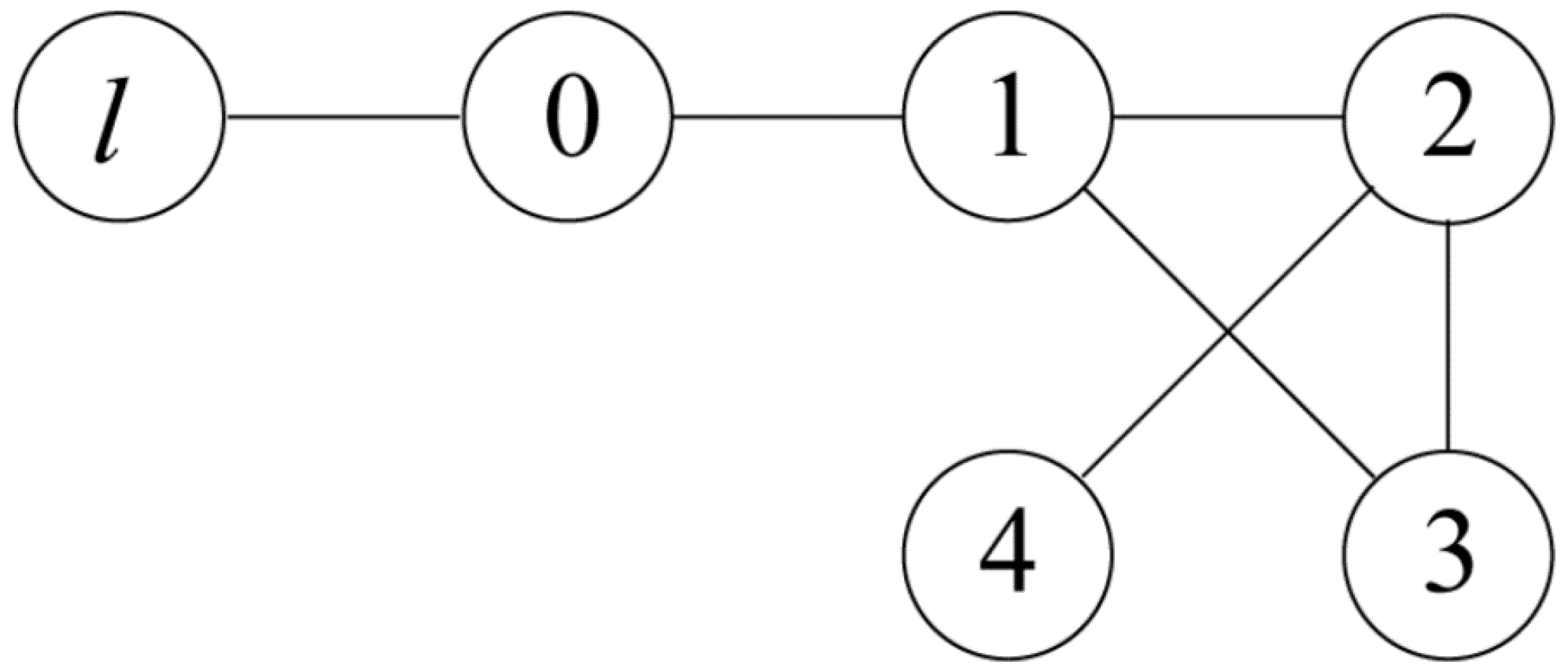
This section will demonstrate the effectiveness and feasibility of the proposed heterogeneous UAVs and USVs collision avoidance formation tracking control strategy by constructing a formation system consisting of one UAV and four USVs. The communication relationship between each agent in the formation is shown in Figure 2.
Where agent l represents virtual leaders, agent 0 represents UAV, and agents 1–4 represent four USVs. If B g = d i a g { 0 , 0 , 0 , 0 , 1 } is the adjacency weight matrix between agents and the virtual leader, then the adjacency matrix A g and the Laplacian matrix L g are defined as follows:
A g = 0 1 1 0 1 1 0 1 1 0 1 1 0 0 0 0 1 0 0 0 1 0 0 0 0 L g = 3 1 1 0 1 1 3 1 1 0 1 1 2 0 0 0 1 0 1 0 1 0 0 0 1
Case 1. Let leader UAV navigates along the time-varying parametric trajectory p 0 = [ 1.2 t , 0.4 t ] T . Table 1 shows the system parameters of UAVs and USVs. The initial states of five HMASs are set as p 1 = [ 0 , 0 , 0 ] T , p 2 = [ 7 , 7 , 0 ] T , p 3 = [ 7 , 7 , 8 ] T , p 4 = [ 14 , 14 , 0 ] T , p 5 = [ 14 , 14 , 0 ] T . In the horizontal plane, defining the desired formation pattern as p 1 d = [ 0 , 0 ] T , p 2 d = [ 7 , 7 ] T , p 3 d = [ 7 , 7 ] T , p 4 d = [ 14 , 14 ] T , p 5 d = [ 14 , 14 ] T . Other relevant parameters are designed as c i U = c i V = 10 , l i U = l i V = 30 , η i U = η i V = 2 , ρ i U = ρ i V = 0.02 , ς i U = ς i V = 0.2 , γ 1 = γ 2 = 2 , k i U = k i V = 0.2 , Γ a x z = 0.3 cos ( 0.2 t ) , Γ a x y = 0.2 cos ( 0.5 t ) , 0.8 cos ( t ) T , ω d i x y = 1.1 cos ( 0.5 t ) , 0.2 sin ( 2 t ) T . The potential function is selected with the parameters R ̲ = 4 , R ¯ = 8 , R o ̲ = 3 , R o ¯ = 5 , K i = d i a g { 0.1 , 0.1 } , ε i = 0.01 .
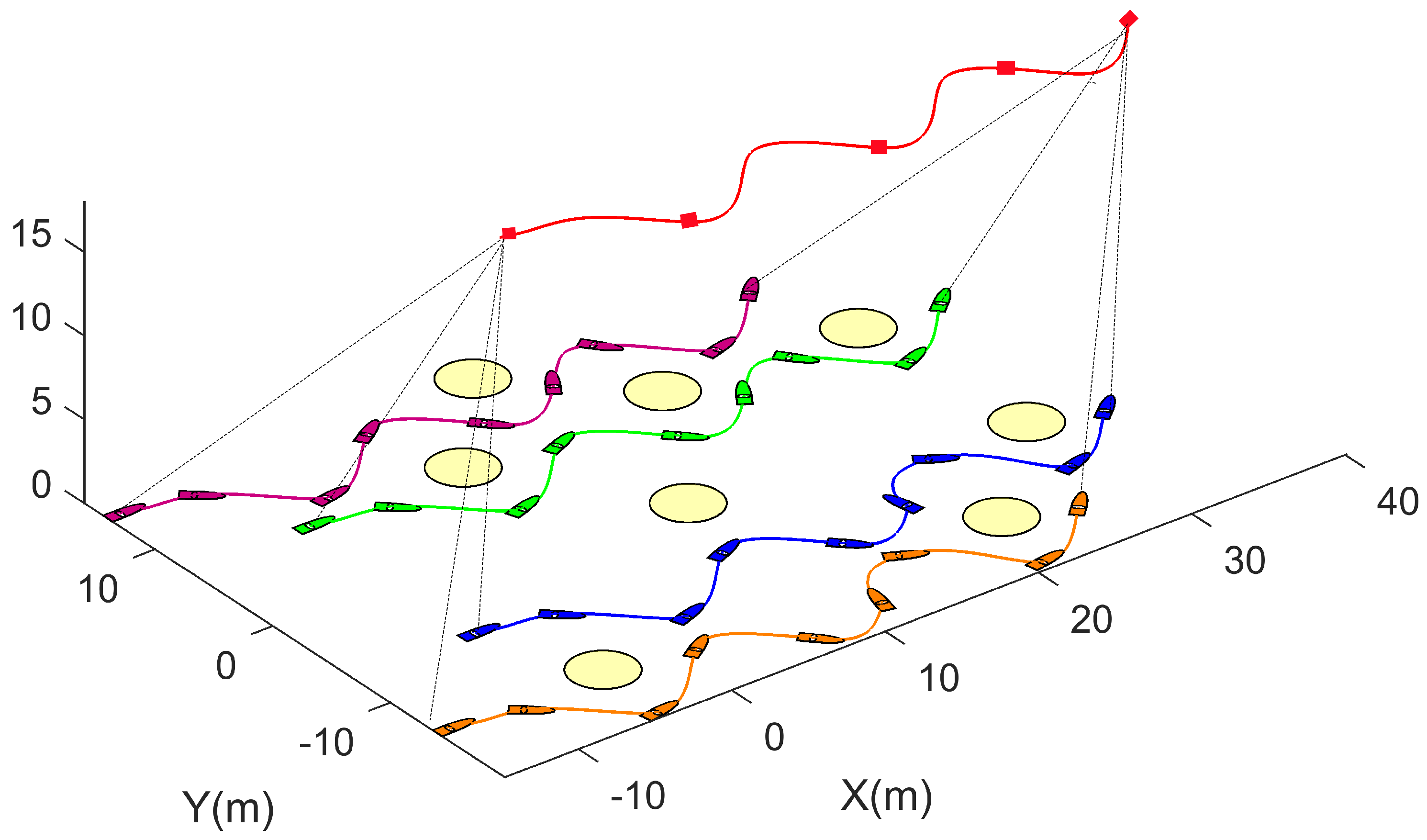
From the simulation results, Figure 3 illustrates the formation trajectories of four USVs and one UAV. It is evident from the figure that the USVs maintain alignment with the UAV along the desired trajectory from their initial positions despite external interference and internal system errors. They autonomously engage in collision avoidance when encountering obstacles, therefore achieving trajectory tracking of the UAV. Figure 4 and Figure 5 display the longitudinal and lateral velocities of the USVs and the UAV in the horizontal plane. It is observed that during normal navigation, velocity variations are minimal; however, during collision avoidance maneuvers, velocity changes become more pronounced. Figure 6 describes the longitudinal control input τ i U and Q ( τ i U ) with and without input quantization. Figure 7 describes the lateral control input τ i V and Q ( τ i V ) with and without input quantization, respectively. Notably, during collision avoidance, the controller provides substantial thrust to the relevant vessel, facilitating successful collision avoidance. Examining Figure 6 and Figure 7 reveals that the quantization process maintains control signal integrity without sacrificing performance. Figure 8 and Figure 9 depict formation tracking errors of the USVs and the UAV in the horizontal plane. During collision avoidance maneuvers, tracking errors temporarily increase due to directional adjustments. However, upon completion of collision avoidance, tracking errors diminish, demonstrating the effectiveness of the designed controller in achieving precise formation tracking.
Case 2. To further discuss the effectiveness of the proposed controller, we compare the proposed quantization controller with the strategy proposed in [59]. Let leader UAV navigate along the reference trajectory p 0 = [ 0.2 t , 2 s i n 0.1 t 3 ] T . The other initial conditions and control design parameters are chosen the same as the counterparts in Case 1.
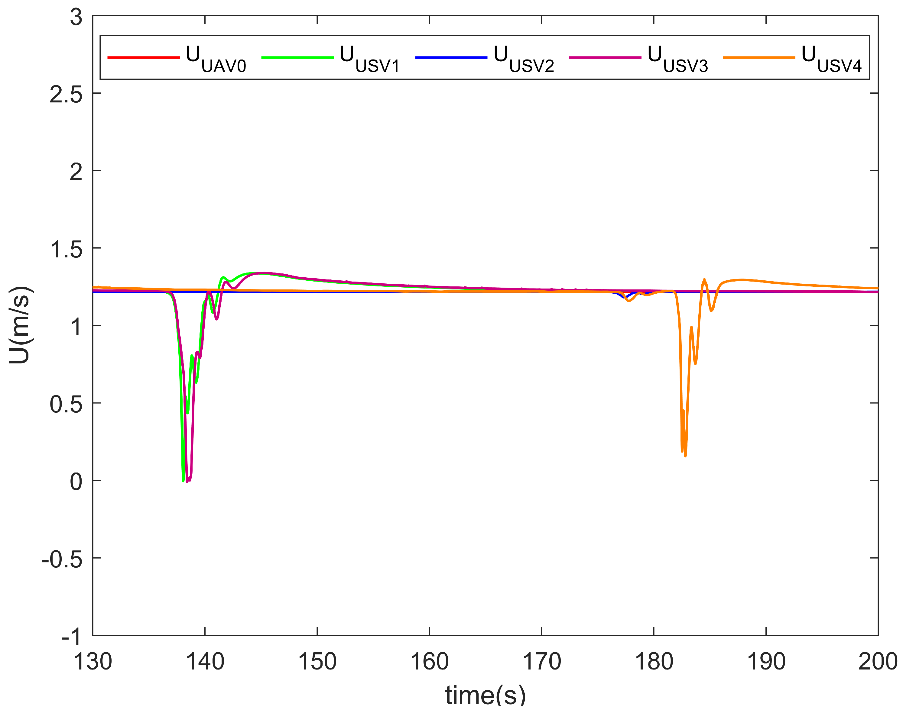
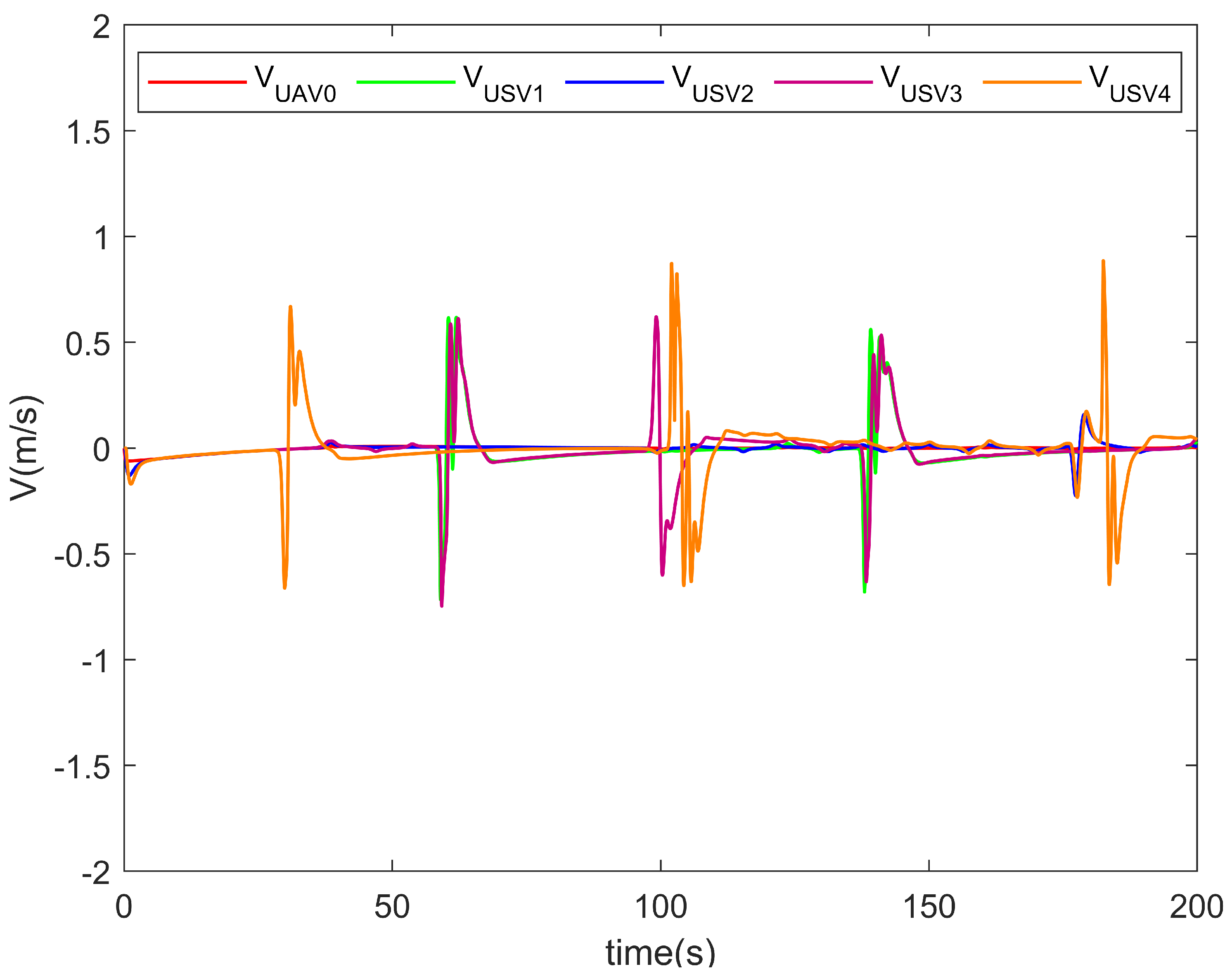
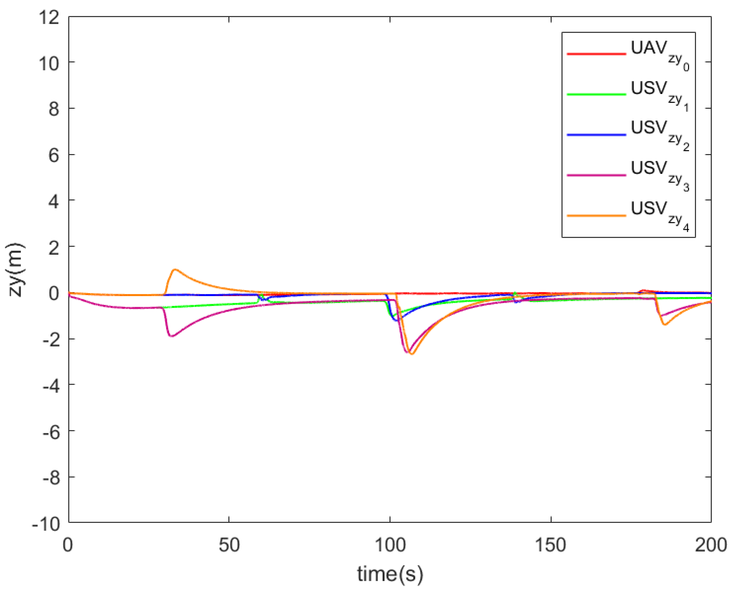
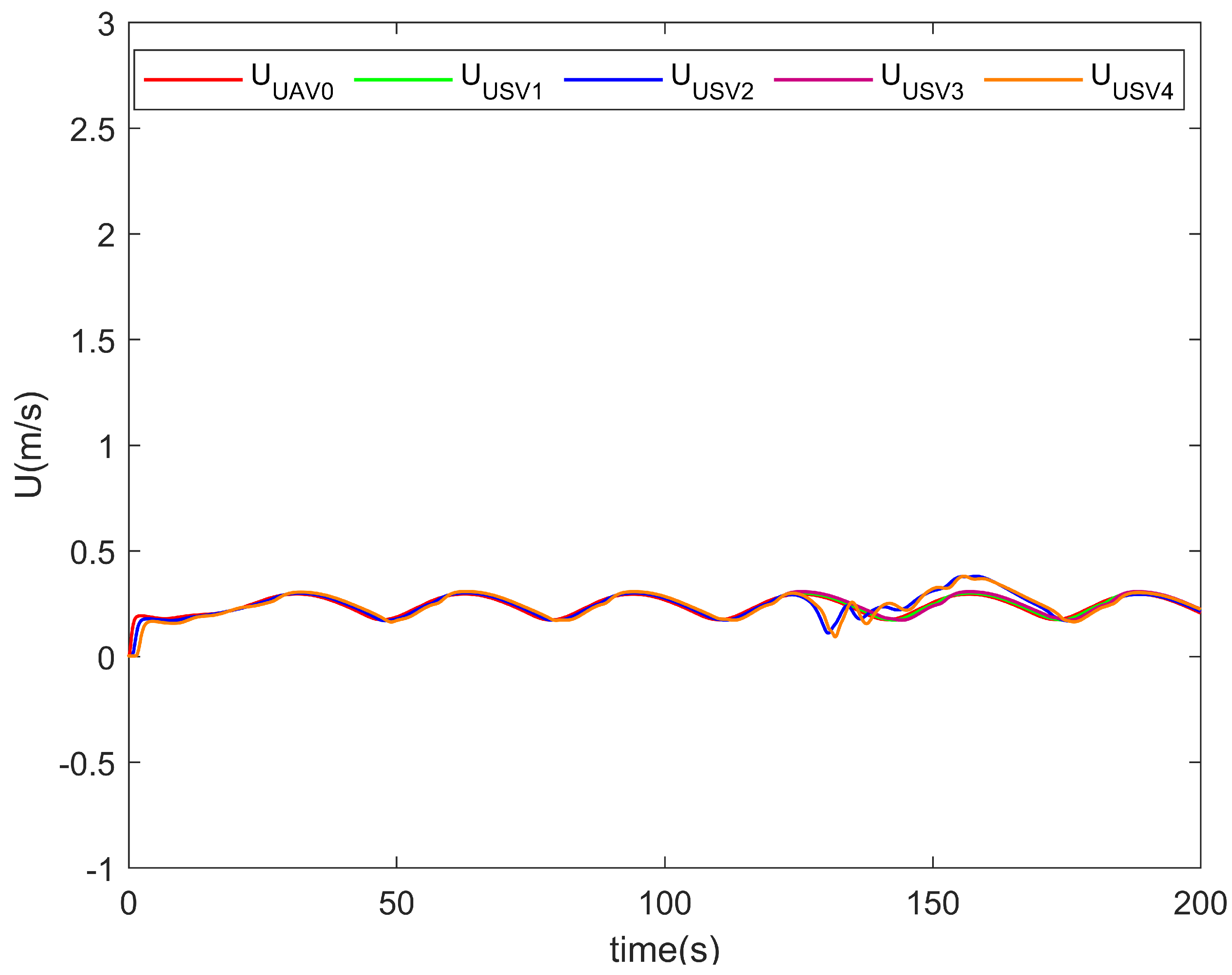
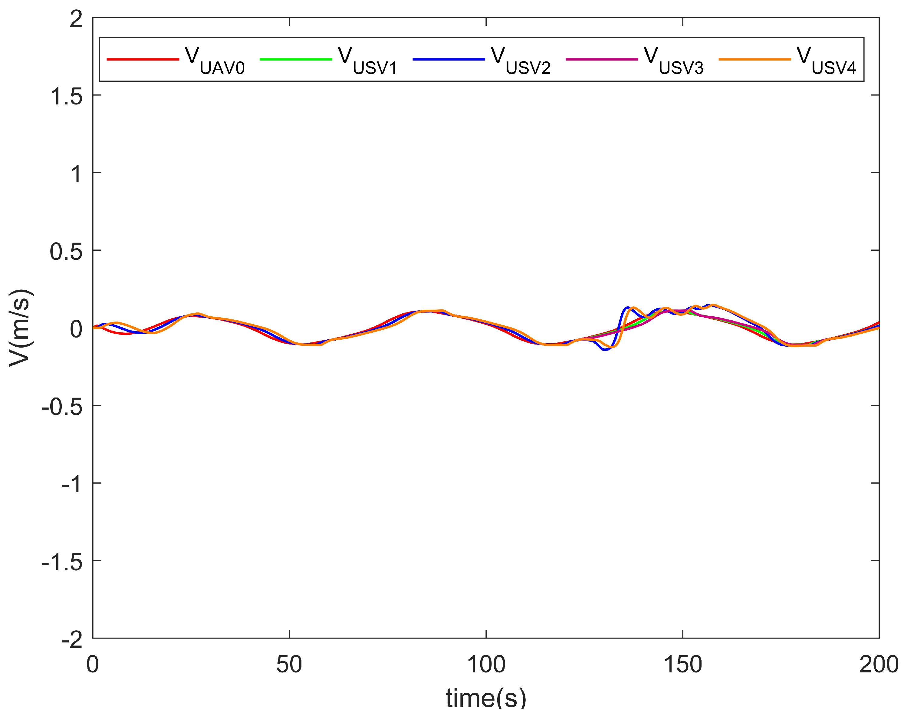
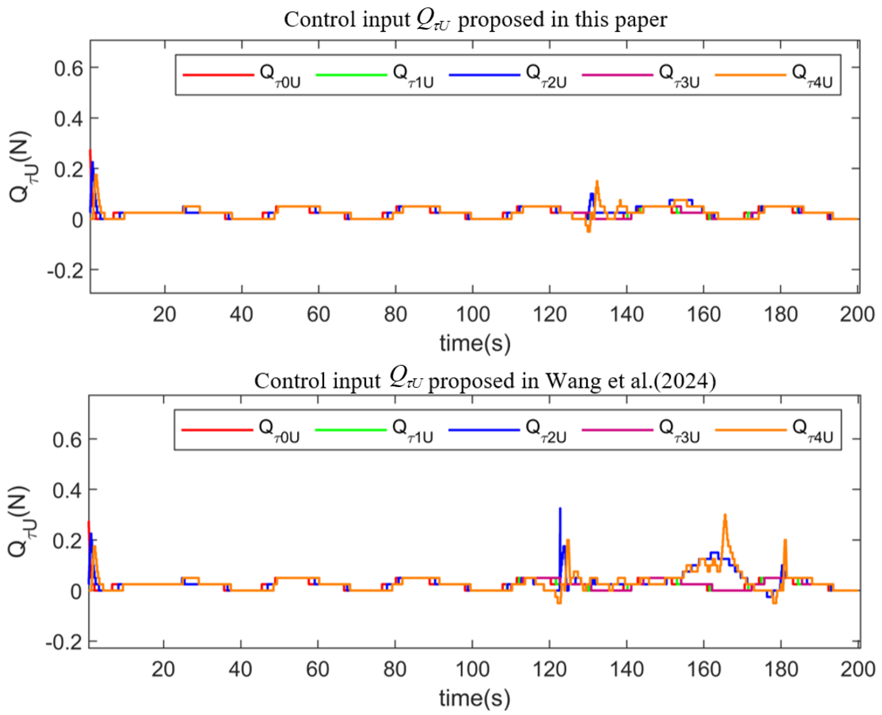
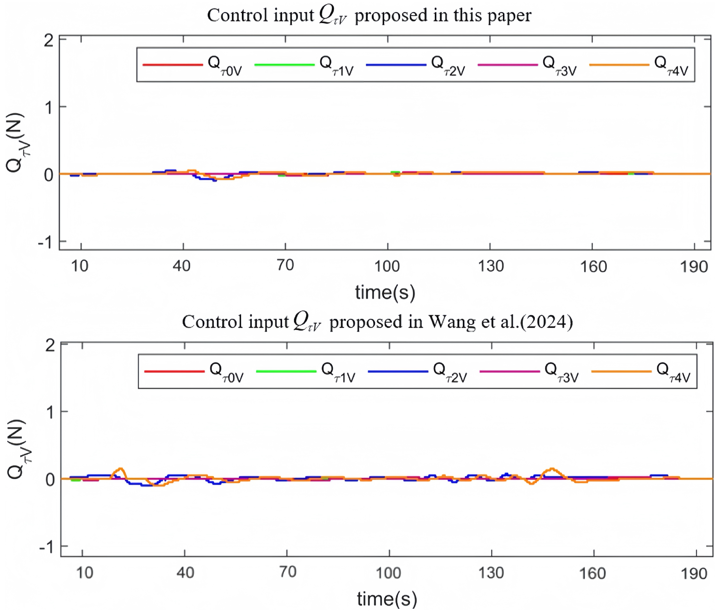
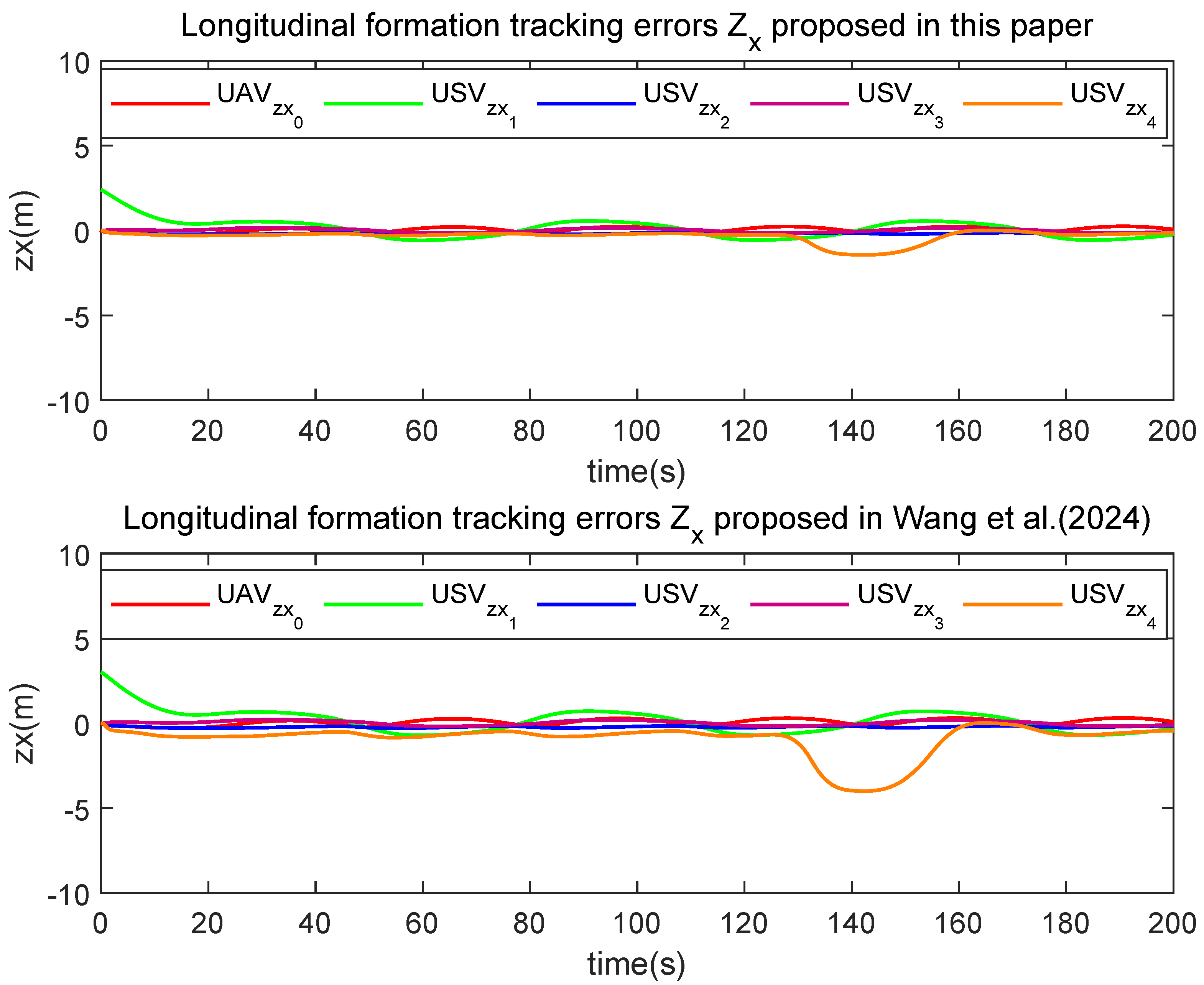
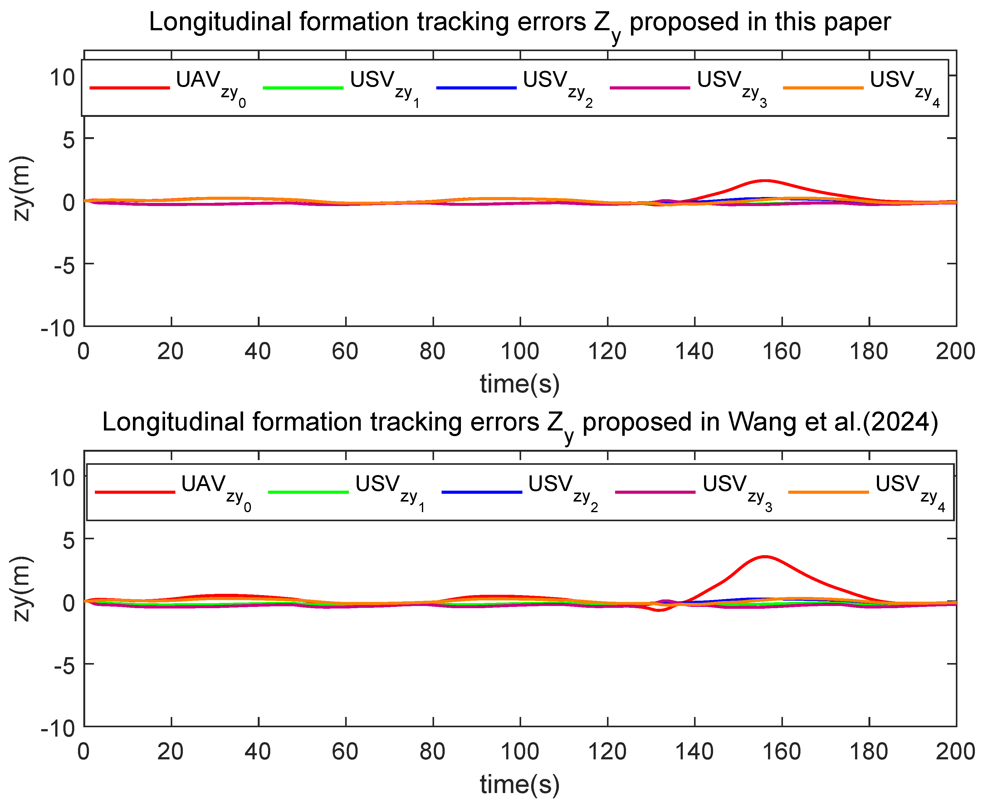
The simulation results are presented in Figure 10, Figure 11, Figure 12, Figure 13, Figure 14, Figure 15 and Figure 16. Figure 10 shows the formation trajectories of the five HMASs. As can be seen from the figure in the XY plane, the five HMASs set off from a given initial position, maintain the desired distance from each other, and remain a special formation under the influence of external interference and system internal error. Figure 11 and Figure 12 display the longitudinal and lateral velocities of the USVs and the UAV in the horizontal plane. Figure 13 and Figure 14 depict the comparison curve of longitudinal control input Q ( τ U ) and lateral control input Q ( τ V ) in different methods, respectively. Figure 15 and Figure 16 present the longitudinal and lateral formation tracking error comparisons between the two control strategies, respectively. The analysis of these figures reveals that the implementation of a linear time-varying model for representing the quantizers leads to reduced tracking errors in the proposed control strategy, thereby enhancing its tracking accuracy.

6. Conclusions

This study delves into the heterogeneous formation control of both UAVs and USVs under conditions of input quantization. The process commences with the unification of the heterogeneous agent models for UAVs and USVs. The control system is structured hierarchically, divided into kinematic and dynamic subsystems based on a consistent horizontal model. The kinematic subsystem accounts for repulsive potential functions between unmanned vessels and obstacles, while neural networks are employed at the dynamic level to estimate uncertain terms and unknown parameters. A linear model is then applied to describe the quantization process for control inputs. Adaptive controllers are subsequently developed for altitude tracking in the vertical plane. Additionally, the stability of the designed heterogeneous formation tracking controller is analyzed using input-to-state stability. Finally, simulation experiments are conducted to validate the effectiveness of the proposed control strategy.
This paper focuses on analyzing the formation dynamics involving a single UAV and multiple USVs. Future research should explore collaborative dynamics and collision avoidance strategies for scenarios involving multiple UAVs and USVs in complex environments. Our forthcoming goal is to integrate formation transformations within the limits of dynamic and static obstacles, aiming to refine the proposed algorithm and demonstrate its efficacy in reducing communication overhead and preserving communication resources in quantized environments.

Author Contributions

Conceptualization, W.L. and J.N.; methodology, H.W. and J.N.; software, H.W.; validation, H.W.; writing—original draft preparation, H.W.; writing—review and editing, H.W., W.L. and J.N.; supervision, W.L. and J.N.; project administration, W.L.; funding acquisition, J.N. All authors have read and agreed to the published version of the manuscript.

Funding

This work was supported in part by the National Natural Science Foundation of China under Grants 51939001, 61976033, 52171292, 52271304 and in part by the Fundamental Research Funds for the Central Universities, China under Grant 3132024137 and in part by the 2023 DMU navigation college first-class interdisciplinary research project, 2023JXA09.

Institutional Review Board Statement

Not applicable.

Informed Consent Statement

Not applicable.

Data Availability Statement

The original contributions presented in this study are included in the article Further inquiries can be directed to the corresponding author.

Conflicts of Interest

The authors declare that they have no conflict of interest.

References

  1. Makhsoos, A.; Mousazadeh, H.; Mohtasebi, S.S. Evaluation of some effective parameters on the energy efficiency of on-board photovoltaic array on an unmanned surface vehicle. Ships Offshore Struct. 2019, 14, 492–500. [Google Scholar] [CrossRef]
  2. Zhao, L.; Bai, Y.; Wang, F.; Bai, J. Path planning for autonomous surface vessels based on improved artificial fish swarm algorithm: A further study. Ships Offshore Struct. 2023, 18, 1325–1337. [Google Scholar] [CrossRef]
  3. Yang, Z.; Li, S.; Yu, D.; Chen, C.P. BLS-based formation control for nonlinear multi-agent systems with actuator fault and input saturation. Nonlinear Dyn. 2022, 109, 2657–2673. [Google Scholar] [CrossRef]
  4. Ma, L.; Wang, Y.L.; Fei, M.R.; Pan, Q.K. Cross-dimensional formation control of second-order heterogeneous multi-agent systems. ISA Trans. 2022, 127, 188–196. [Google Scholar] [CrossRef]
  5. Ennong, T.; Ye, L.; Teng, M.; Yulei, L.; Yueming, L.; Jian, C. Design and experiment of a sea-air heterogeneous unmanned collaborative system for rapid inspection tasks at sea. Appl. Ocean Res. 2024, 143, 103856. [Google Scholar] [CrossRef]
  6. Hou, H.Q.; Liu, Y.J.; Liu, L.; Lan, J. Adaptive fuzzy formation control for heterogeneous multi-agent systems using time-varying IBLFs. Nonlinear Dyn. 2023, 111, 16077–16091. [Google Scholar] [CrossRef]
  7. Mazare, M.; Asharioun, H.; Davoudi, E.; Mokhtari, M. Distributed finite-time neural network observer-based consensus tracking control of heterogeneous underwater vehicles. Ocean Eng. 2023, 272, 113882. [Google Scholar] [CrossRef]
  8. Li, X.; Yao, J. A nonlinear model predictive control method for ship path following in waves. Ships Offshore Struct. 2024, 1–14. [Google Scholar] [CrossRef]
  9. Wu, G.; Xu, T.; Sun, Y.; Zhang, J. Review of multiple unmanned surface vessels collaborative search and hunting based on swarm intelligence. Int. J. Adv. Robot. Syst. 2022, 19, 17298806221091885. [Google Scholar] [CrossRef]
  10. Liu, C.; Wang, Y. Neural adaptive performance guaranteed formation control for USVs with event-triggered quantized inputs. Ships Offshore Struct. 2024, 1–13. [Google Scholar] [CrossRef]
  11. Ma, S.; Guo, W.; Song, R.; Liu, Y. Unsupervised learning based coordinated multi-task allocation for unmanned surface vehicles. Neurocomputing 2021, 420, 227–245. [Google Scholar] [CrossRef]
  12. Sun, Z.; Sun, H.; Li, P.; Zou, J. Self-organizing cooperative pursuit strategy for multi-USV with dynamic obstacle ships. J. Mar. Sci. Eng. 2022, 10, 562. [Google Scholar] [CrossRef]
  13. Liang, Q.; Huang, H.; Huang, B.; Hu, S.; Yang, C. Three-dimensional deployment strategy for a multi-BWBUG cooperative system at deep depths. Ships Offshore Struct. 2024, 1–19. [Google Scholar] [CrossRef]
  14. Cui, Y.; Peng, L.; Li, H. Filtered probabilistic model predictive control-based reinforcement learning for unmanned surface vehicles. IEEE Trans. Ind. Inform. 2022, 18, 6950–6961. [Google Scholar] [CrossRef]
  15. Ning, J.; Ma, Y.; Liu, L.; Li, T. Fuzzy course tracking control of an unmanned surface vehicle with event-triggered mechanism and input quantization. Ocean Eng. 2023, 288, 115704. [Google Scholar] [CrossRef]
  16. Deng, Z.; Wang, Z.; Shen, W. Formation control of unmanned surface vehicles with position estimation algorithm. Mech. Sci. Technol. Aerosp. Eng. 2022, 41, 623–633. [Google Scholar]
  17. Zhang, J.; Yan, J.; Zhang, P. Multi-UAV formation control based on a novel back-stepping approach. IEEE Trans. Veh. Technol. 2020, 69, 2437–2448. [Google Scholar] [CrossRef]
  18. Do, H.T.; Hua, H.; Nguyen, M.T.; Nguyen, V.-C.; Nguyen, H.; Nga, N.T.T.; Nguyen, N.T. Formation control algorithms for multiple-uavs: A comprehensive survey. EAI Endorsed Trans. Ind. Netw. Intell. Syst. 2021, 8, e3. [Google Scholar] [CrossRef]
  19. Yan, M.-d.; Zhu, X.; Zhang, X.-x.; Qu, Y.-h. Consensus-based three-dimensionalmulti-UAV formation control strategy with high precision. Front. Inf. Technol. Electron. Eng. 2017, 18, 968–977. [Google Scholar] [CrossRef]
  20. Ke, C.; Chen, H.; Xie, L. Cross-Domain Fixed-Time Formation Control for an Air-Sea Heterogeneous Unmanned System with Disturbances. J. Mar. Sci. Eng. 2023, 11, 1336. [Google Scholar] [CrossRef]
  21. Haoliang, W.; Chenyang, Y.; Liyu, L.; Dan, W.; Zhouhua, P. Cooperative path following control of UAV and USV cluster for maritime search and rescue. Chin. J. Ship Res. 2022, 17, 157–165. [Google Scholar]
  22. Xue, K.; Wu, T. Distributed consensus of USVs under heterogeneous UAV-USV multi-agent systems cooperative control scheme. J. Mar. Sci. Eng. 2021, 9, 1314. [Google Scholar] [CrossRef]
  23. Lui, D.G.; Petrillo, A.; Santini, S. Leader tracking control for heterogeneous uncertain nonlinear multi-agent systems via a distributed robust adaptive PID strategy. Nonlinear Dyn. 2022, 108, 363–378. [Google Scholar] [CrossRef]
  24. Zhen, Q.; Wan, L.; Li, Y.; Jiang, D. Formation control of a multi-AUVs system based on virtual structure and artificial potential field on SE(3). Ocean Eng. 2022, 253, 111148. [Google Scholar] [CrossRef]
  25. Carreras, M.; Batlle, J.; Ridao, P.; Roberts, G. An overview on behaviour-based methods for AUV control. IFAC Proc. Vol. 2000, 33, 141–146. [Google Scholar] [CrossRef]
  26. Karkoub, M.; Wang, H.; Wu, T.S. Distributed Newton and Quasi-Newton methods for formation control of autonomous vehicles. Ships Offshore Struct. 2020, 15, 61–74. [Google Scholar] [CrossRef]
  27. Yu, H.; Zhang, S. Collaborative task decision-making of multi-UUV in dynamic environments based on deep reinforcement learning. Sips Offshore Struct. 2024, 1–11. [Google Scholar] [CrossRef]
  28. Li, M.; Chen, Y.; Hu, K.; Pan, C.; Mao, Z. Observer-based decentralized fuzzy control for connected nonlinear vehicle systems. Nonlinear Dyn. 2023, 111, 7321–7337. [Google Scholar] [CrossRef]
  29. Glotzbach, T.; Schneider, M.; Otto, P. Cooperative line of sight target tracking for heterogeneous unmanned marine vehicle teams: From theory to practice. Robot. Auton. Syst. 2015, 67, 53–60. [Google Scholar] [CrossRef]
  30. Lu, E.; Tian, Z.; Xu, L.; Ma, Z.; Luo, C. Observer-based robust cooperative formation tracking control for multiple combine harvesters. Nonlinear Dyn. 2023, 111, 15109–15125. [Google Scholar] [CrossRef]
  31. Dong, Z.; Zhang, Z.; Qi, S.; Zhang, H.; Li, J.; Liu, Y. Autonomous cooperative formation control of underactuated USVs based on improved MPC in complex ocean environment. Ocean Eng. 2023, 270, 113633. [Google Scholar] [CrossRef]
  32. Zhang, H.; Zhang, X.; Xu, H.; Soares, C.G. Heterogeneous cooperative trajectory tracking control between surface and underwater unmanned vehicles. Ocean Eng. 2024, 301, 117137. [Google Scholar] [CrossRef]
  33. Wang, H.; Tian, Y.; Xu, H. Neural adaptive command filtered control for cooperative path following of multiple underactuated autonomous underwater vehicles along one path. IEEE Trans. Syst. Man Cybern. Syst. 2021, 52, 2966–2978. [Google Scholar] [CrossRef]
  34. Liu, H.; Weng, P.; Tian, X.; Mai, Q. Distributed adaptive fixed-time formation control for UAV-USV heterogeneous multi-agent systems. Ocean Eng. 2023, 267, 113240. [Google Scholar] [CrossRef]
  35. Li, S.; Wang, X.; Wang, S.; Zhang, Y. Distributed bearing-only formation control for uav-uwsv heterogeneous system. Drones 2023, 7, 124. [Google Scholar] [CrossRef]
  36. Huang, D.; Li, H.; Li, X. Formation of generic UAVs-USVs system under distributed model predictive control scheme. IEEE Trans. Circuits Syst. II Express Briefs 2020, 67, 3123–3127. [Google Scholar] [CrossRef]
  37. Li, Y.; Liu, M.; Lian, J.; Guo, Y. Collaborative optimal formation control for heterogeneous multi-agent systems. Entropy 2022, 24, 1440. [Google Scholar] [CrossRef]
  38. Weng, P.; Tian, X.; Liu, H.; Mai, Q. Distributed edge-based event-triggered optimal formation control for air-sea heterogeneous multiagent systems. Ocean Eng. 2023, 288, 116066. [Google Scholar] [CrossRef]
  39. Yuan, Z.; Zhao, L.; Tian, S.; Zhang, D. A maritime image dehazing algorithm based on improved VQGAN. Ships Offshore Struct. 2024, 1–15. [Google Scholar] [CrossRef]
  40. Liu, C. Neural-network-based distributed formation tracking control of marine vessels with heterogeneous hydrodynamics. IEEE Access 2019, 7, 150141–150149. [Google Scholar] [CrossRef]
  41. Lv, C.; Chen, J.; Yu, H.; Chi, J.; Yang, Z. Adaptive NN state error PCH trajectory tracking control for unmanned surface vessel with uncertainties and input saturation. Asian J. Control 2023, 25, 3903–3919. [Google Scholar] [CrossRef]
  42. Choi, Y.H.; Yoo, S.J. Distributed quantized feedback design strategy for adaptive consensus tracking of uncertain strict-feedback nonlinear multiagent systems with state quantizers. IEEE Trans. Cybern. 2021, 52, 7069–7083. [Google Scholar] [CrossRef] [PubMed]
  43. Zhu, Z.; Yin, Y.; Lyu, H. Automatic collision avoidance algorithm based on route-plan-guided artificial potential field method. Ocean Eng. 2023, 271, 113737. [Google Scholar] [CrossRef]
  44. Zhu, Z.; Lyu, H.; Zhang, J.; Yin, Y. An efficient ship automatic collision avoidance method based on modified artificial potential field. J. Mar. Sci. Eng. 2022, 10, 3. [Google Scholar] [CrossRef]
  45. Hao, L.Y.; Zhang, H.; Guo, G.; Li, H. Quantized sliding mode control of unmanned marine vehicles: Various thruster faults tolerated with a unified model. IEEE Trans. Syst. Man Cybern. Syst. 2019, 51, 2012–2026. [Google Scholar] [CrossRef]
  46. Fang, X.; Zhou, J.; Wen, G. Location game of multiple unmanned surface vessels with quantized communications. IEEE Trans. Circuits Syst. II Express Briefs 2021, 69, 1322–1326. [Google Scholar] [CrossRef]
  47. Xiong, S.; Wu, Q.; Wang, Y. Distributed Coordination of Heterogeneous Multi-agent Systems with Dynamic Quantization and L 2- L Control. Int. J. Control Autom. Syst. 2020, 18, 2468–2481. [Google Scholar] [CrossRef]
  48. Zheng, B.C.; Yang, G.H. Quantized output feedback stabilization of uncertain systems with input nonlinearities via sliding mode control. Int. J. Robust Nonlinear Control 2014, 24, 228–246. [Google Scholar] [CrossRef]
  49. Hamidaoui, M.; Talhaoui, M.Z.; Li, M.; Midoun, M.A.; Haouassi, S.; Mekkaoui, D.E.; Smaili, A.; Cherraf, A.; Benyoub, F.Z. Survey of Autonomous Vehicles’ Collision Avoidance Algorithms. Sensors 2025, 25, 395. [Google Scholar] [CrossRef]
  50. Huang, S.; Teo, R.S.H.; Tan, K.K. Collision avoidance of multi unmanned aerial vehicles: A review. Annu. Rev. Control 2019, 48, 147–164. [Google Scholar] [CrossRef]
  51. Peng, Z.; Wang, J.; Wang, D. Distributed maneuvering of autonomous surface vehicles based on neurodynamic optimization and fuzzy approximation. IEEE Trans. Control Syst. Technol. 2017, 26, 1083–1090. [Google Scholar] [CrossRef]
  52. Peng, Z.; Wang, J.; Wang, D.; Han, Q.L. An overview of recent advances in coordinated control of multiple autonomous surface vehicles. IEEE Trans. Ind. Inform. 2020, 17, 732–745. [Google Scholar] [CrossRef]
  53. Peng, Z.; Wang, D.; Wang, J. Data-driven adaptive disturbance observers for model-free trajectory tracking control of maritime autonomous surface ships. IEEE Trans. Neural Netw. Learn. Syst. 2021, 32, 5584–5594. [Google Scholar] [CrossRef]
  54. Ning, J.; Li, T.; Chen, C.P. Neuro-adaptive distributed formation tracking control of under-actuated unmanned surface vehicles with input quantization. Ocean Eng. 2022, 265, 112492. [Google Scholar] [CrossRef]
  55. Ning, J.; Ma, Y.; Li, T.; Chen, C.P.; Tong, S. Event-triggered Based Trajectory Tracking Control of Under-actuated Unmanned Surface Vehicle with State and Input Quantization. IEEE Trans. Intell. Veh. 2023, 9, 3127–3139. [Google Scholar] [CrossRef]
  56. Gu, N.; Wang, D.; Peng, Z.; Liu, L. Observer-based finite-time control for distributed path maneuvering of underactuated unmanned surface vehicles with collision avoidance and connectivity preservation. IEEE Trans. Syst. Man Cybern. Syst. 2019, 51, 5105–5115. [Google Scholar] [CrossRef]
  57. Peng, Z.; Gu, N.; Zhang, Y.; Liu, Y.; Wang, D.; Liu, L. Path-guided time-varying formation control with collision avoidance and connectivity preservation of under-actuated autonomous surface vehicles subject to unknown input gains. Ocean Eng. 2019, 191, 106501. [Google Scholar] [CrossRef]
  58. Peng, Z.; Wang, D.; Li, T.; Han, M. Output-feedback cooperative formation maneuvering of autonomous surface vehicles with connectivity preservation and collision avoidance. IEEE Trans. Cybern. 2019, 50, 2527–2535. [Google Scholar] [CrossRef]
  59. Wang, W.; Wang, Y.; Li, T. Distributed Formation Maneuvering Quantized Control of Under-Actuated Unmanned Surface Vehicles with Collision and Velocity Constraints. J. Mar. Sci. Eng. 2024, 12, 848. [Google Scholar] [CrossRef]
  60. Liu, L.; Wang, D.; Peng, Z.; Han, Q.L. Distributed path following of multiple under-actuated autonomous surface vehicles based on data-driven neural predictors via integral concurrent learning. IEEE Trans. Neural Netw. Learn. Syst. 2021, 32, 5334–5344. [Google Scholar] [CrossRef]
  61. Liu, S.; Jiang, B.; Mao, Z.; Ma, Y. Adaptive fault-tolerant formation control of heterogeneous multi-agent systems under directed communication topology. Sensors 2022, 22, 6212. [Google Scholar] [CrossRef] [PubMed]
  62. Peng, Z.; Liu, L.; Wang, J. Output-feedback flocking control of multiple autonomous surface vehicles based on data-driven adaptive extended state observers. IEEE Trans. Cybern. 2020, 51, 4611–4622. [Google Scholar] [CrossRef]
Figure 1. Motion model of USVs.
Actuators 14 00309 g001
Figure 2. Communication topology graph.
Actuators 14 00309 g002
Figure 3. Motion model of USVs and UAV.
Actuators 14 00309 g003
Figure 4. The longitudinal velocity of USVs and UAV.
Actuators 14 00309 g004
Figure 5. The lateral velocity of USVs and UAV.
Actuators 14 00309 g005
Figure 6. The comparison of longitudinal control inputs for USVs and UAV.
Actuators 14 00309 g006
Figure 7. The comparison of lateral control inputs for USVs and UAV.
Actuators 14 00309 g007
Figure 8. The longitudinal formation tracking errors.
Actuators 14 00309 g008
Figure 9. The lateral formation tracking errors.
Actuators 14 00309 g009
Figure 10. Motion model of USVs and UAV in Case 2.
Actuators 14 00309 g010
Figure 11. The longitudinal velocity of USVs and UAV.
Actuators 14 00309 g011
Figure 12. The lateral velocity of USVs and UAV.
Actuators 14 00309 g012
Figure 13. Comparison of longitudinal control inputs.
Actuators 14 00309 g013
Figure 14. Comparison of lateral control inputs.
Actuators 14 00309 g014
Figure 15. Comparison of longitudinal formation tracking errors.
Actuators 14 00309 g015
Figure 16. Comparison of lateral formation tracking errors.
Actuators 14 00309 g016
Table 1. System parameters of UAV and USVs.
ParameterValueUnit
m a 25.8kg
g9.8 N · kg 1
J a x , J a y , J a z 1.5 N · s 2 · rad 1
d x , d y , d z 0.012 N · s 2 · rad 1
m i μ 25.8 kg
m i v 33.8kg
m i r 2.76kg
d u s i 0.725 kg · s 1
d v s i 0.89 kg · s 1
d r s i −1.9 kg · m 2 · s 1
f i μ 5.87 μ 3 1.33 μ μ 0.72 μ + m i v v r + 1.0948 r 2
f i v 36.5 v v 0.8896 v 0.805 v r m i μ μ r
f i r 0.75 r r 1.90 r + 0.08 v r
+ ( m i u m i v ) μ v 1.0948 μ r
Disclaimer/Publisher’s Note: The statements, opinions and data contained in all publications are solely those of the individual author(s) and contributor(s) and not of MDPI and/or the editor(s). MDPI and/or the editor(s) disclaim responsibility for any injury to people or property resulting from any ideas, methods, instructions or products referred to in the content.