Article

Precision Pressure Pump Featuring Dual-Valve Control and Onboard Compression for Microfluidic Systems

Department of Mechanical Engineering, Université du Québec à Trois-Rivières (UQTR), 3351 Bd des Forges, Trois-Rivières, QC G8Z 4M3, Canada
*
Author to whom correspondence should be addressed.
Actuators 2025, 14(12), 593; https://doi.org/10.3390/act14120593
Submission received: 18 September 2025 / Revised: 30 October 2025 / Accepted: 10 November 2025 / Published: 4 December 2025
(This article belongs to the Special Issue Design, Hydrodynamics, and Control of Mechatronic Systems)

Abstract

The essence of microfluidics lies in its ability to manipulate fluids within compact and portable systems. However, existing pressure pumps rely on bulky external compressors and are costly. Open-source solutions are generally suited for passive microfluidic applications due to their slow settling times (1500–2500 s). The innovative pressure regulator developed uses two proportional solenoid valves and a built-in compression unit. The pressure regulation is ensured by a Proportional–Integral–Derivative (PID) controller. A comparative analysis is conducted between the developed regulator and a commercial regulator (Marsh Bellofram). Both regulators provide a comparable accuracy of about ±0.01 psi (±0.7 mbar) from the desired pressure. However, our regulator demonstrates a faster settling time (∼100 ms vs. ∼200 ms), which is particularly desirable for implementation in an active system, while offering a lower price (∼USD 250 vs. ∼USD 1000). We present a cost-effective, compact pressure pump that does not rely on bulky compressors. It delivers fast and precise pressure, even at low pressure, making it suitable for both active and passive microfluidic applications. This design improves access to pressure regulation in microfluidics for low-budget laboratories and limited infrastructure environments.

1. Introduction

Microfluidics manipulates small amounts of fluids, introducing numerous advantages in different sectors such as biomedical and chemical research [1,2,3], soft microrobotics [4,5,6], environmental science [7,8,9,10], photobioreactors for microalgae [11,12], and many other fields. Methods used to control fluids in microchannels are classified into two main approaches: passive and active [13,14,15,16,17,18]. Passive devices depend on physical forces and the geometry of the microchannels, functioning as an open-loop system with limited control over the flow. In contrast, active devices precisely control the flow with external forces such as controlled pressure [19,20], electric [21], and magnetic fields [22,23,24]. Active systems incorporate sensors and controllers that operate in a closed-loop system, sometimes relying on the dynamic system model [25,26,27,28,29,30]. In microfluidic applications involving pressure control, passive applications require a stable pressure source [31]; however, active applications depend on fast and precise pressure control.
The device employed to control the flow in microscopic channels significantly impacts the performance and functionality of microfluidic applications [32]. Several pump techniques are used in microfluidics, including the use of pneumatic pressure pumps, peristaltic pumps [33,34,35], and syringe pumps, among others, as reviewed by P. Iakovlev et al. [36] and Byun et al. [37]. Pressure pumps outperform other pumps due to their ability to drive stable, precise, pulse-free flow with fast response time [38]. In addition, pneumatic pumps reduce the risk of contamination in microfluidic systems, as only dry air comes into contact with the flow. Last but not least, these pumps offer flexibility in handling various volumes by providing control over multiple flows using only one pump.
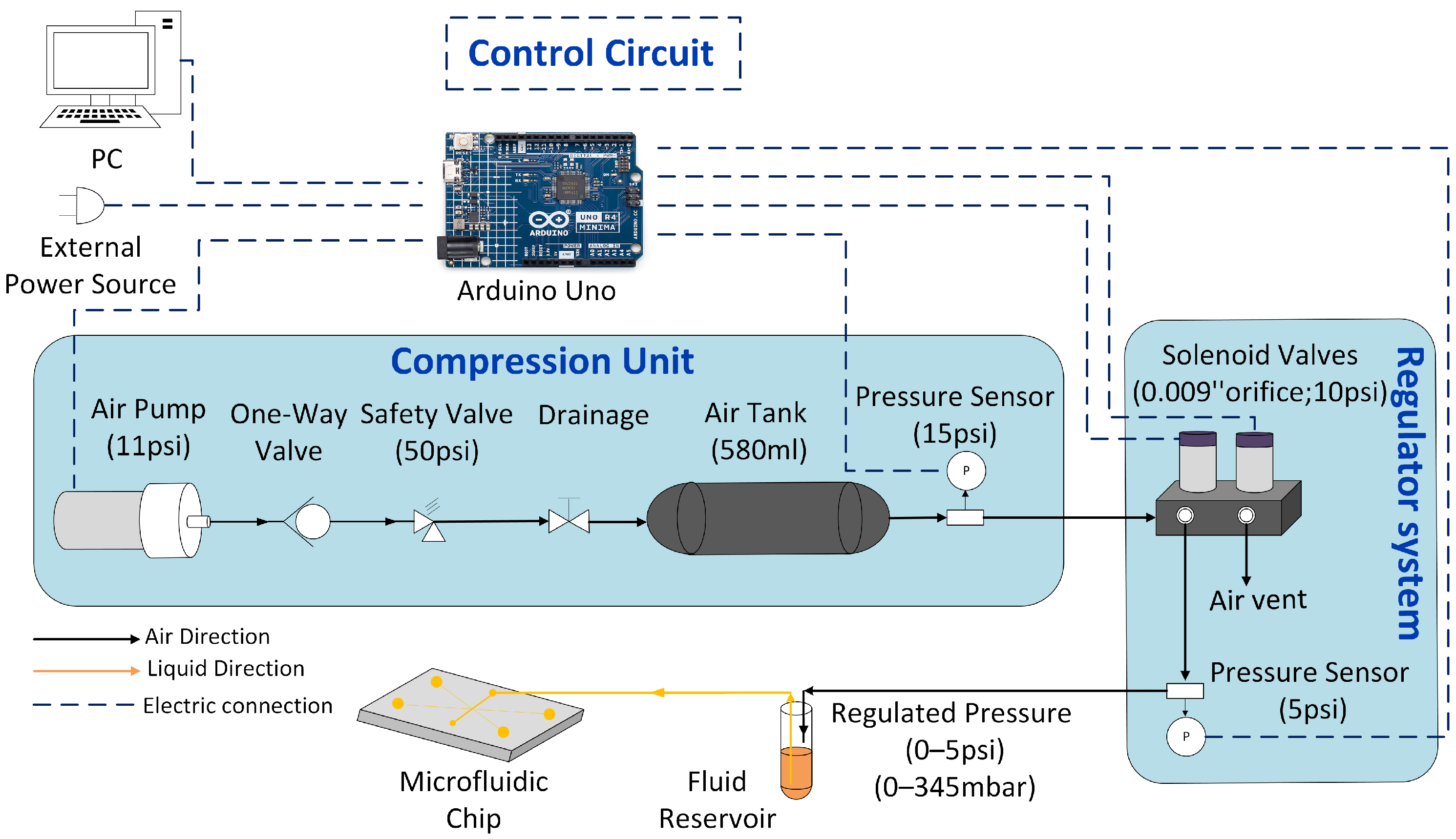
The working principle of the pressure pump is illustrated in Figure 1. The device operates by regulating compressed air to a desired set level. The regulated air is applied to a fluid reservoir containing a certain amount of liquid, which is then pushed into a microfluidic chip. This mechanism is controlled by a microcontroller that adjusts the system to reach the desired pressure set by users.
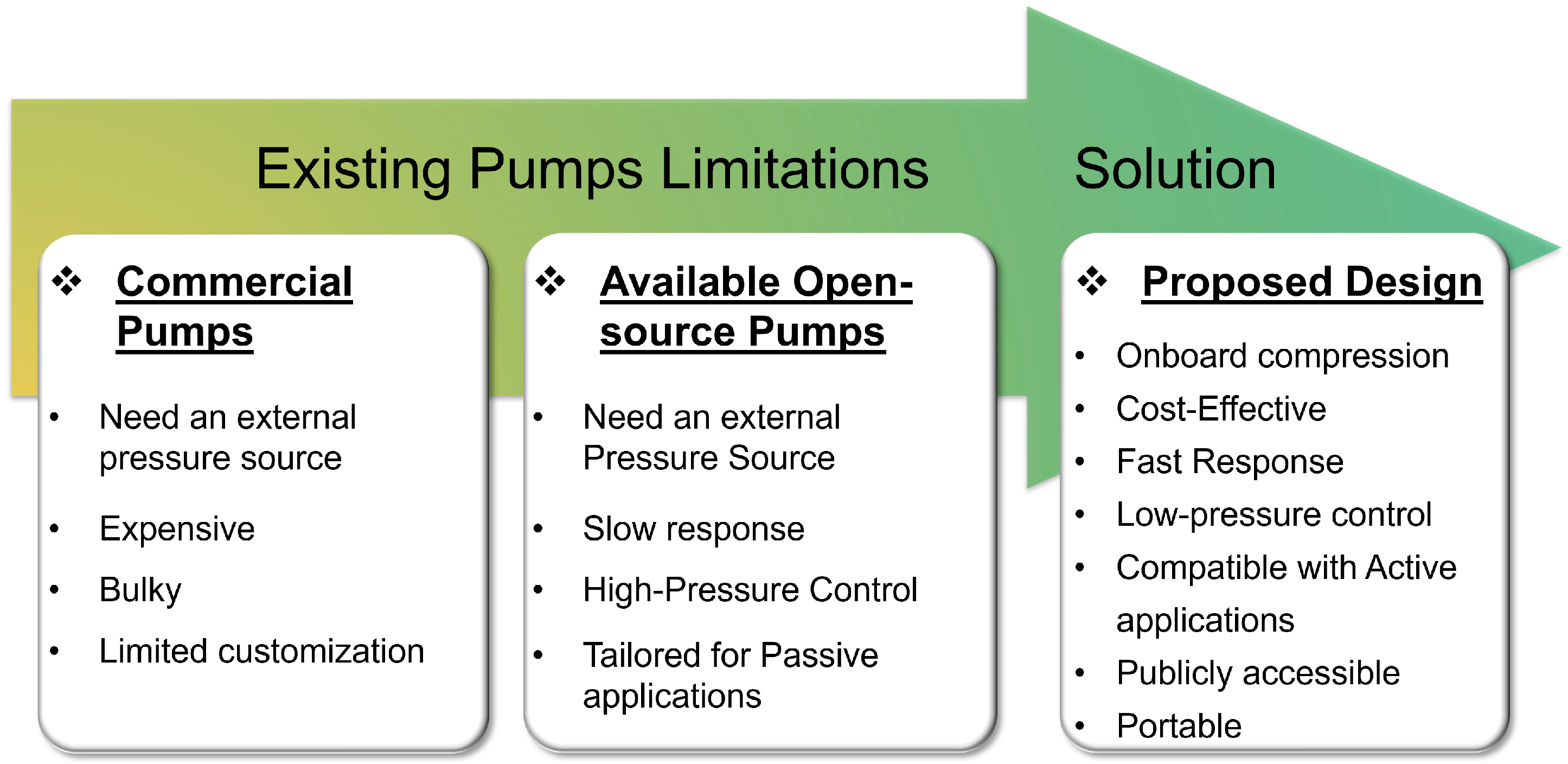
Figure 2 summarizes the limitations of existing pressure pumps and presents the solution offered by the developed design in this study to address these limitations. Microfluidics’ elegance is centered on miniaturization; hence, pressure pumps that require bulky compressors to operate defeat this main principle. Commercial pressure pumps offer high performance. However, their high cost and lack of customization and the need for an external pressure source limit their accessibility to laboratories with significant resources. Previous studies have introduced solutions addressing some of these limitations by presenting open-source pressure pump options, whose hardware and design information are publicly available to allow users to replicate and modify them based on their needs at an affordable cost compared to commercially available systems. The focus of this paper will be on the actuation method; however, some open-source projects include more components such as the microfluidic device [39]. Some of these studies rely on commercial pressure regulators to develop their open-source pressure pump. For example, Gao et al. [40] and Filatov et al. [41] use electro-pneumatic modules in their design, while Ernits et al.’s [42] design employs piezoelectric regulators. However, commercial pressure regulators are still slightly expensive and have a slower settling time compared to commercial pressure pumps such as Elveflow and Fluigent. Alternatively, Sanchez et al. [43] present an open-source pressure pump featuring an open-source pressure regulator using two proportional solenoid valves. However, the price and the settling time remain comparable to those of commercial ones. Notably, these pumps are generally tailored to provide stable pressure flow for passive microfluidic applications, as they exhibit slow settling time (on the order of seconds). Additionally, these studies do not provide a solution for the compressed air supply. Watson et al. [44] develop a fully integrated system equipped with an air pump as a pressure source and a pressure regulator using two proportional solenoid valves. Nonetheless, their system is specifically built to control pneumatic-driven microfluidic chips with their 32 solenoid valves rather than driving fluid into the chip. Another open-source system focuses on the control of many solenoid valves; the targeted systems are two-layer microfluidic chips with integrated control valves [45].
Only positive pressure actuation methods are herein considered. Vacuum systems that supply negative relative pressures are omitted [46,47].
The novel pressure pump presented herein addresses the constraints of current commercial and open-source models by implementing several strategies. The pump is equipped with an onboard compression system. This eliminates the need for an external pressure source, which is beneficial in environments with limited infrastructure. However, minor additional heat and noise are generated from the compression unit. Crucially, we developed an innovative pressure regulator using two proportional solenoid valves per independent pressure output that interact to achieve the desired set pressure. The mechanism between the two valves is controlled by a designed PID control system. The regulator offers precise pressure control with an accuracy of ±0.01 psi (±0.7 mbar) from the desired pressure and a fast settling time of less than 100 ms. The performance of our regulator is compared to a commercial pressure regulator (Marsh Bellofram). Our regulator exhibits faster settling time (∼100 ms vs. ∼200 ms) and a lower price (∼USD 250 vs. ∼USD 1000) with closely comparable accuracy. Therefore, our pump is compatible with both active and passive microfluidic applications, and it is designed to be easily accessible and customizable to meet specific users’ requirements.

2. Hardware Setup

Figure 1 presents the schematic for our developed pressure pump. The system’s hardware consists of three primary parts: the compression unit, the regulator system, and the control circuit. These components are integrated to form the final design. The build details are presented in the Supplementary Material, including a bill of materials, the PCB files, the software, and the mechanical assembly.

2.1. Compression Unit

The first part of our study involves providing a pressure source in the system that is portable and energy-efficient and delivers the required pressure. This eliminates the need for an external pressure source, allowing for the implementation of the pump in a wider range of environments where a pressure source is a constraint.
The compression unit comprises an air pump (AP-3P04, SmartProducts, Rd.Mills River, NC, USA) that generates pressurized air up to 10 psi. A one-way valve prevents backflow. Additionally, a safety valve is included to protect the system in case the pressure exceeds 50 psi, and a drainage valve is available to release air from the system when needed. The compressed air is then stored in a reservoir of 580 mL volume. The connection between the one-way valve, tee branches, and the air tank is enabled through 1/4″ OD × 0.16″ polyurethane tubing. The air tank acts as a buffer to maintain steady airflow, dampen the fluctuation in the air pump, and reduce the continuous running of the pump. The tank is connected to another 1/4″ OD push-to-connect tee branch with a brass barbed straight fitting (1/16″, # 10-32). Using silicone tubing (1/16″ ID), the barb is connected to the pressure sensor (ABPDANV015PGAA5, Honeywell Sensing and Productivity Solutions, Charlotte, NC, USA; operating pressure 0–15 psi) mounted on the custom Arduino Shield printed circuit board (PCB). The pressure sensor measures the air pressure in the compression unit supplied to the regulator system. The air tank reaches a pressure of 9.5 psi in approximately 50 s. When the pressure in the tank reaches 10 psi, the air pump turns off, and it turns back on when the pressure drops below 5.5 psi based on the pressure sensor reading. The starting and stopping of the pump cause small disturbances to the system that are handled by the control loop. During the design stage, a trade-off occurs between the air tank volume, the pump maximum pressure, and the expected lifespan of the compression unit.
The system is customizable, and utilizing different types of pumps with varying pressure outputs is feasible. However, its compatibility with other components in the system, like the safety valve and the pressure sensor, must be verified. In addition, the system can easily be connected to an external pressure source if available, offering better flexibility for users. However, validation must be performed for the control parameters if the input pressure is significantly higher or lower.

2.2. Regulator System

The main contribution of this study is the development of a custom pressure regulator instead of using commercial options, as in several other open-source pressure pump studies. The custom regulator stands out due to its significantly reduced price, and most importantly, its fast settling time is suitable for active microfluidic applications.
The developed regulator operates using two proportional solenoid valves (EV-PM-05-0905-V, Clippard, Cincinnati, OH, USA). One valve manages air supplied from the compression unit, and the second valve vents excess air to the atmosphere, as presented in Figure 1. The two valves are mounted on the fill and bleed manifold (EFB-2M, Clippard, Cincinnati, OH, USA). The outlet from the manifold is connected to a 1/4″ OD push-to-connect tee branch. One branch provides air to the pressure sensor (ABPDANT005PGAA5, Honeywell Sensing and Productivity Solutions, Charlotte, NC, USA; operating pressure 0–5 psi), while the other directs the regulated air (0–5 psi) to a vial, then to a microfluidic chip. The sensor is mounted on the “solenoid valve PCB” and continuously monitors the outlet air pressure to provide real-time feedback to the control system. The Proportional–Integral–Derivative (PID) controller driven by Arduino processes the data to regulate the system and maintain the desired pressure within a closed-loop system. The control system is comprehensively discussed in the following section.

2.3. Control Circuit

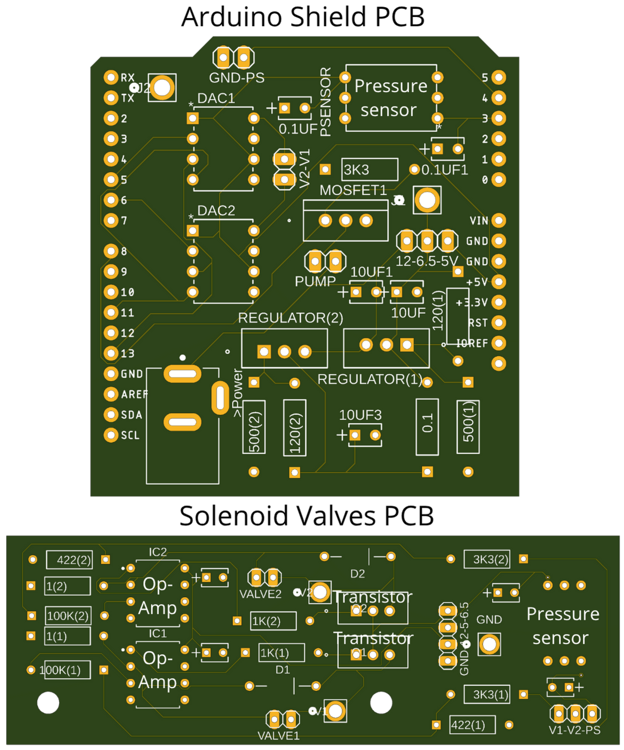
The proportional solenoid valves are current-driven with a 0–5 V control signal. To achieve precise control over the valve opening and the flow rate, an electronic circuit regulates the current supplied to the valves within the controllable range of 0–350 mA. The circuit consists of an operational amplifier (LM358P, Texas Instruments, Dallas, TX, USA), a transistor (TIP120ST, STMicroelectronics, Geneva, Switzerland), resistors, and capacitors. A detailed schematic is included in the Supplementary Material. Figure 3 shows the PCB implementation for the “solenoid valve PCB” including the feedback pressure sensor (ABPDANT005PGAA5, Honeywell Sensing and Productivity Solutions, Charlotte, NC, USA; operating pressure 0–5 psi).
The “Arduino Shield PCB” incorporates two 12-bit digital-to-analog converters (DAC) (MCP4921-E/P, Microchip Technology, Chandler, AZ, USA) that provide a 0–5 V control signal for the valves. Two voltage regulators (LD1085V, STMicroelectronics, Geneva, Switzerland) supply 6.5 V to the valves by stepping down the 12 V from the external power source. A MOSFET (RFP12N10L, Onsemi, Scottsdale, AZ, USA) controls power supplied to the air pump. A pressure sensor (ABPDANV015PGAA5, Honeywell Sensing and Productivity Solutions, Charlotte, NC, USA; operating pressure 0–15 psi) measures the pressure in the air tank. The PCB is mounted directly on the Arduino. The custom “Arduino Shield PCB” supplies power and signal to the solenoid valve PCB by seven wires: four power wires (12 V, 6.5 V, 5 V, ground) and three signal wires for the pressure sensor (ps) and the two valves (V1, V2).

2.4. Final Design

By integrating the compression unit, the regulator system, and the control circuit, we developed the prototype version of the pump, presented in the Supplementary Material. This open setup enables testing before enclosing the pump in a portable box. Moreover, it provides an easy-to-replicate option for users who prefer to avoid the more complex housing process or wish to design a custom enclosure.
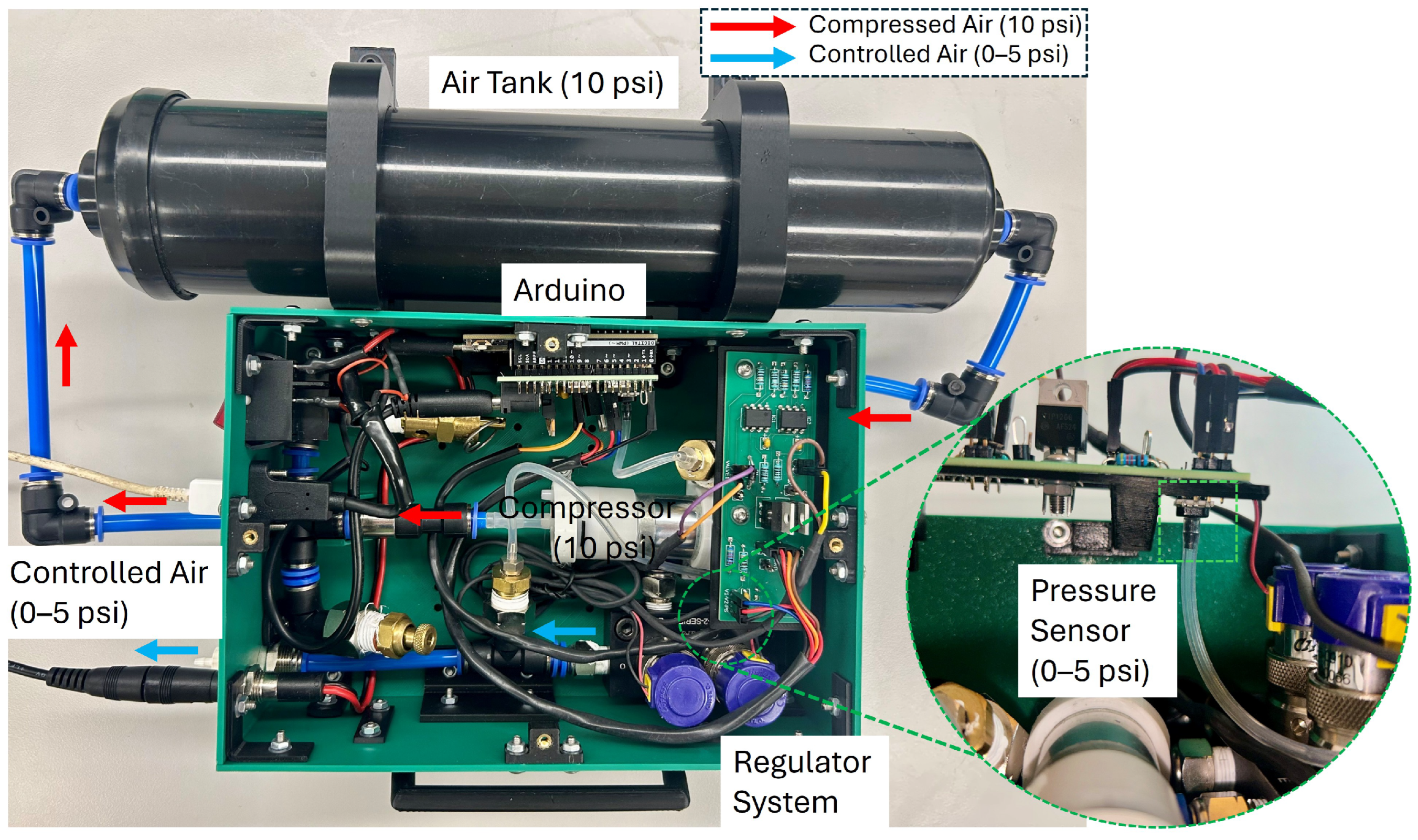
Figure 4 shows the final version of the enclosed pressure pump developed herein for better compactness and portability. We provide detailed instructions on the steps followed to enclose the pump in the Supplementary Material. The pump is space-efficient at ∼330 in3 (0.0054 m3;) and lightweight at ∼3 lbs (1.5 kg). To operate, it must be connected to a computer using a USB to run the Arduino code and to set the desired pressure. Additionally, the pump requires a 12 V external power source from a wall adapter.

3. Control System

3.1. Air Volume Model

A simplified system is considered to analyze stability in Equation (1). Certain characteristics of the physical system are neglected, more specifically, discretization effects, hysteresis, actuator saturation, damping, and filtering. The volume is filled with an ideal gas (air) that has a net mass flow. The first proportional valve adds gas from the supply, while the second proportional valve vents gas to the atmosphere.
p ˙ = R a i r T V γ m ˙ n e t
The pressure must be converted to psi to match the output of the system sensor. For the input, the variable u is expressed in volts with the 1.84 (L/min)/A factor based on the linear relationship of the valve (see Supplementary Materials for details). Thus, the system dynamics are summarized with a constant parameter ( α ). In the frequency domain, the transfer function of the plant is thus essentially an integrator.
p ˙ = α · u = 81.2 p s i / s V · u
G p l a n t ( s ) = P ( s ) U ( s ) = α s

3.2. PID Control and Equilibrium

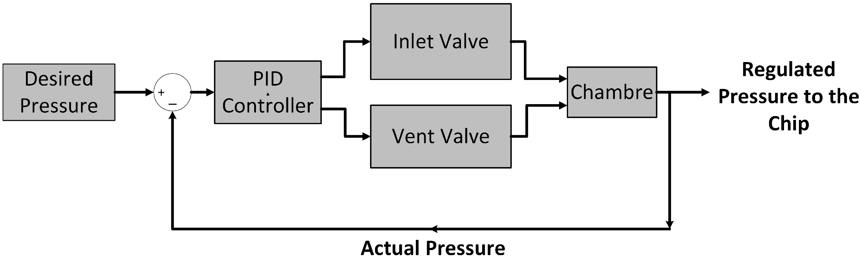
This study intends to make the pressure pump accessible and user-friendly. Therefore, the control system used is the widely known Proportional–Integral–Derivative (PID) control system. Moreover, implementation is conducted on the easily accessible Arduino platform. The control system regulates the two proportional valves. One valve increases the pressure, while the second releases air to achieve the desired pressure based on real-time measurements from the pressure sensor in a closed-loop system, as illustrated in Figure 5.
Both valves are controlled by a single PID output signal. Hence, the system exhibits nonlinear behavior. This makes tuning the system using classical methods such as Cohen–Coon and Ziegler–Nichols, which depend on simplified system models, inapplicable. Furthermore, many factors affect the system, including air leakage, tubing length, sensor positioning, and actuation delay, which differ among built prototypes. Providing analytical methods through equations or a simulation model that accommodates variables across different setups can be complicated, particularly for users without strong mathematical backgrounds.
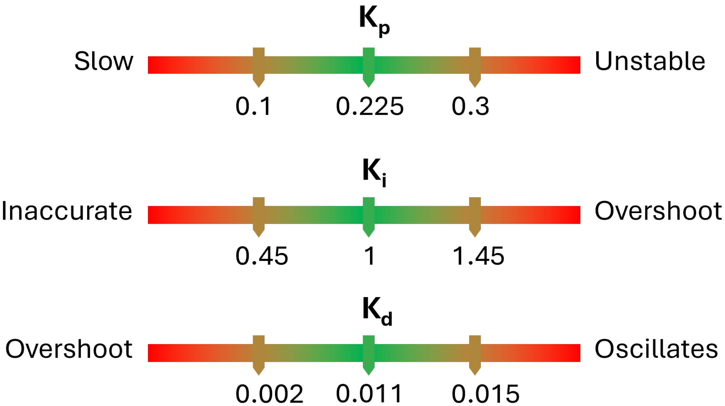
As a result, the pressure regulator is tuned experimentally by conducting a systematic series of tests while adjusting the controller gain parameters ( K p K i , and  K d ) based on the measured performance. The performance focuses on the speed at which the desired pressure is reached (settling time (95%)) and the precision the regulator exhibits at the desired pressure (mean error between the actual and desired pressures). Figure 6 presents the gain values that lead to adequate system performance, offering a reference guide and a starting point for users to tune their pumps to meet their specific application’s needs. The compressed air supplied can affect the behavior of the regulator system. Thus, these values are applicable when the supplied pressure is below 10 psi; a pressure above 10 psi may require an adjustment of these values.
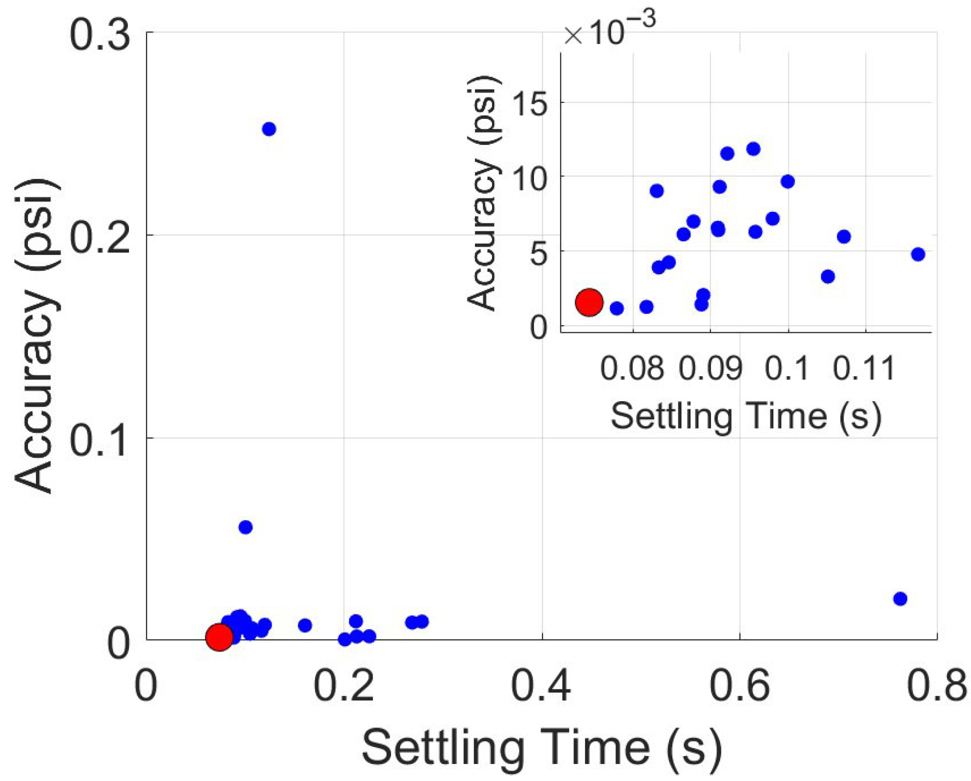
The suitable gain values for the pump presented herein are selected based on the trade-off between settling time and accuracy, as illustrated in Figure 7, showing the Pareto front. The red-marked point indicates the best trade-off, corresponding to the following gain values:  K p  = 0.225;  K i  = 1;  K d  = 0.011. The corresponding controller transfer function is given in Equation (4).
G c t r l ( s ) = K p + K i s + K d · s
The two solenoid valves do not operate sequentially but simultaneously. This strategy is required to dampen the fluctuations in the system and achieve suitable performance. This is implemented in the Arduino code (Arduino IDE 2.3.5) in the Supplementary Materials, and it can be summarized by the following equations:
u 1 = u , if u > 0 U max | u | , if u < 0 u 1 f , if u = 0
u 2 = U max u , if u > 0 | u | , if u < 0 u 2 f , if u = 0
Here,  u 1  and  u 2  are the control signals applied to valve 1 and valve 2, respectively; u is the PID controller output;  U max  is the maximum DAC output value where the valves are fully open at 3000; and  u 1 f  and  u 2 f  represent the final values applied to valve 1 and valve 2, respectively, when u reaches 0.
Both valves are open simultaneously but at different values to provide a net mass flow ( m ˙ n e t ) to the air volume. This equilibrium is determined based on the volume pressure, atmospheric pressure (0 when considering gauge pressures), and the compressor supply pressure (see Equation (7)). The proportional valve opening at equilibrium will be different if the supply pressure is modified and depending on whether the control signal u is positive or negative. Both valves are considered identical with the same flow coefficient k.
m ˙ n e t = k u p s u p p l y p k ( U m a x u ) p p a t m , if u > 0 k ( U m a x | u | ) p s u p p l y p k | u | p p a t m , if u < 0
The valve opening values at equilibrium ( m ˙ n e t = 0 ) are expressed as normalized pressure by the supply pressure in Equation (8). The expressions vary between 0 and 1 and between 1 and 0 for  u > 0  and  u < 0 , respectively.
p p s u p p l y = u 2 ( U m a x u ) 2 + u 2 , if u > 0 ( U m a x | u | ) 2 ( U m a x | u | ) 2 + u 2 , if u < 0

3.3. Stability

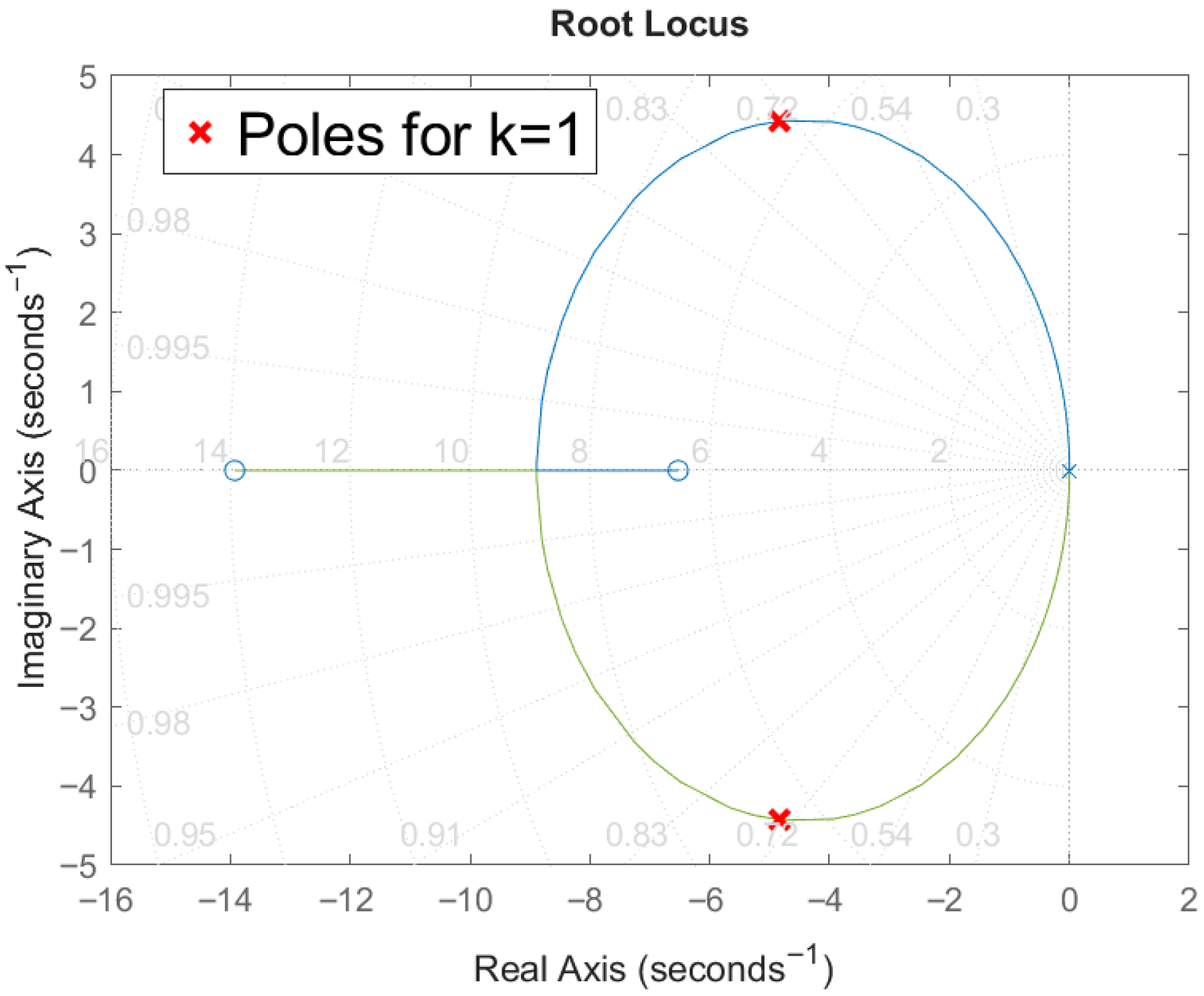
The stability of the closed-loop system (plant and controller) is analyzed using a root locus plot and a Bode diagram. The root locus plot in Figure 8 shows that the poles remain on the left-hand side of the s-plane, and thus, this ensures stability no matter the applied gain k. Therefore, this indicates that the system is stable even if the value of alpha changes (scaled by k), while the PID controller gains are considered constant (or scaled uniformly).
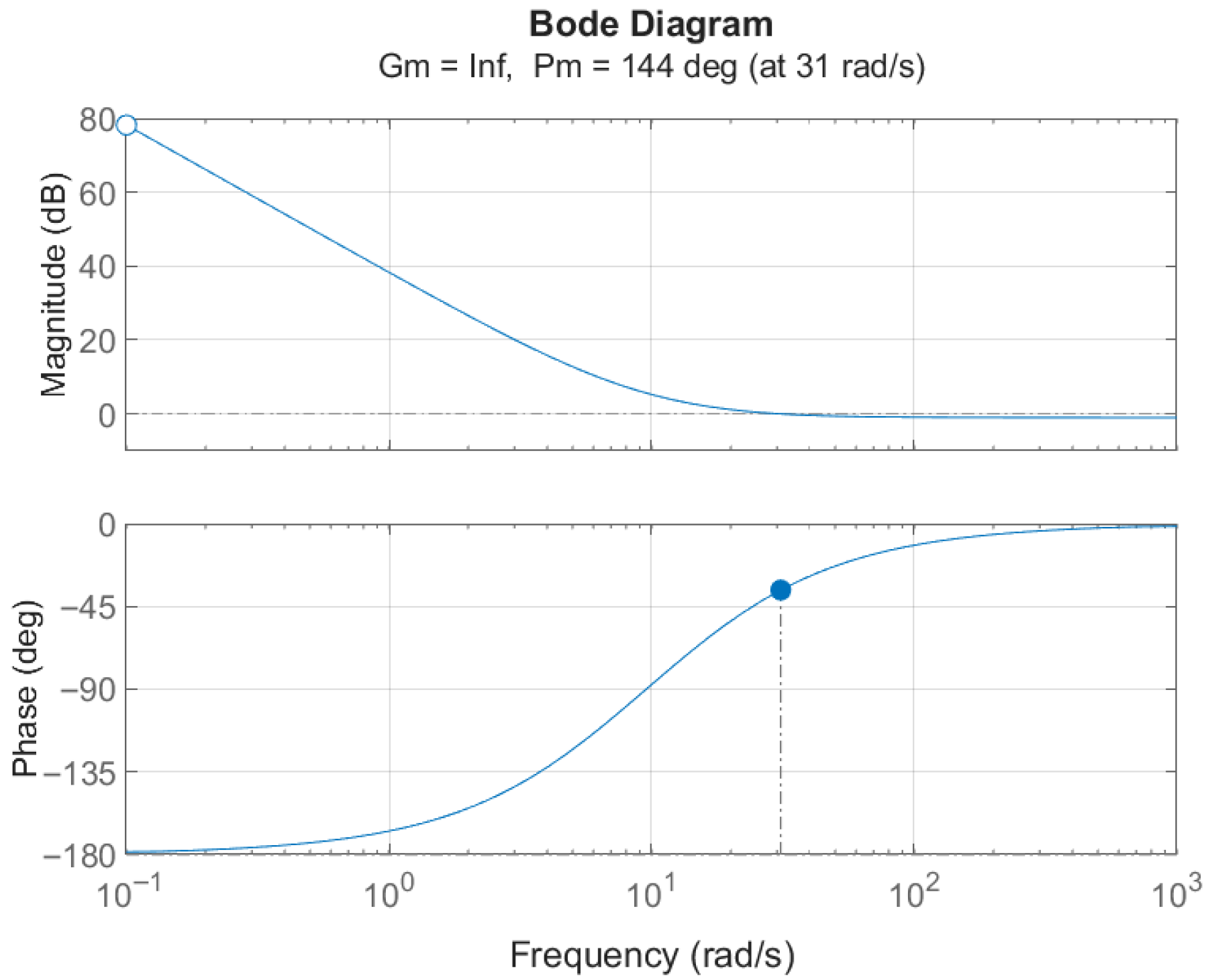
The Bode plot of the system (see Figure 9) shows a phase margin of 144°. This indicates a stable closed-loop system. Moreover, the gain margin of infinity is in accordance with the root locus previously discussed (stable for any gain k).

4. Performance Evaluation

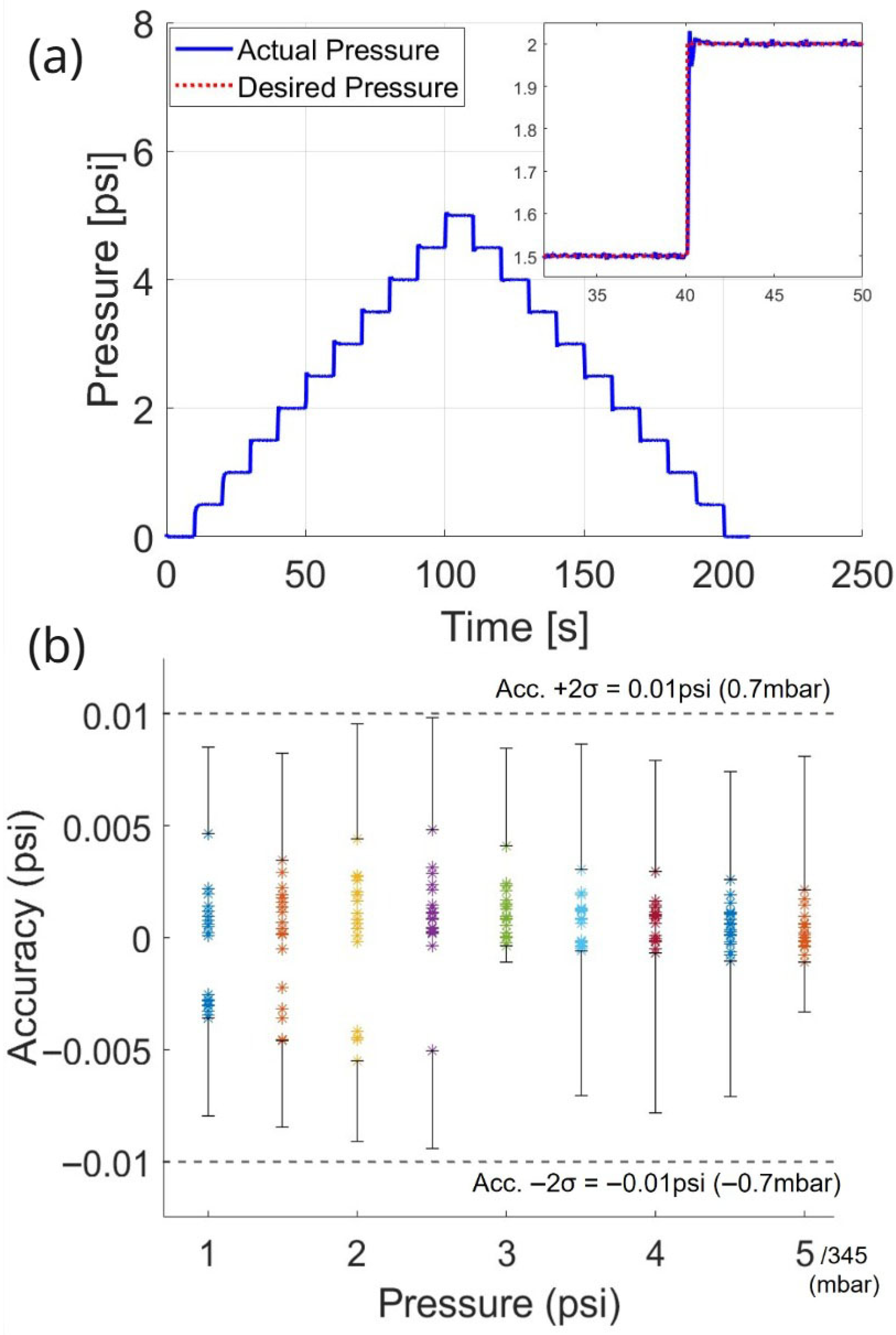
In this section, the proposed system’s performance is evaluated with the assembled components and implemented control strategy. The compression unit provides compressed air up to 10 psi. Pressure regulation is tested by increasing the set pressure gradually from 0 to 5 psi in 0.5 increments and then decreasing it back to 0 psi. The system performs very effectively, as shown in Figure 10, with all the desired pressures being reached quickly and precisely. However, at a low pressure of 0.5 psi, the system’s performance sometimes deteriorates significantly. The performance at this low pressure range could be improved by tuning the gain values accordingly; however, the resulting performance at higher pressure would suffer. Therefore, this low pressure is excluded from the quantified performance evaluation.
The system response is recorded 20 times to assess the settling time of the regulator at each set pressure for every trial. The values are summarized in Table 1. The last column shows the average settling time across all pressures for each trial. Red colors mark the slowest settling times, while green colors indicate the fastest settling times. The performance deteriorates at low pressures that we consider outside of the operating range of this pump. This trade-off enables high consistency and fast settling time for the rest of the pressures. The overall average settling time for the 20 trials is 80 ms, with a variation (2* standard deviation ( σ )) of ±12 ms.
The system’s accuracy is evaluated with the average error between the set pressure and the actual pressure reading from the pressure sensor. Each dataset includes 500 sample points at each pressure level across the 20 trials. The results are presented by the 20 dots for each pressure level on the graph in Figure 10. The maximum mean error added to twice the standard deviation ( σ ) is approximately ±0.01 psi at a pressure level of 2.5 psi, and all the mean errors remain within this range. Thus, the pressure regulator demonstrates high accuracy with an error range of ±0.01 psi (±0.2% F.S).

5. Comparative Analysis and Discussion

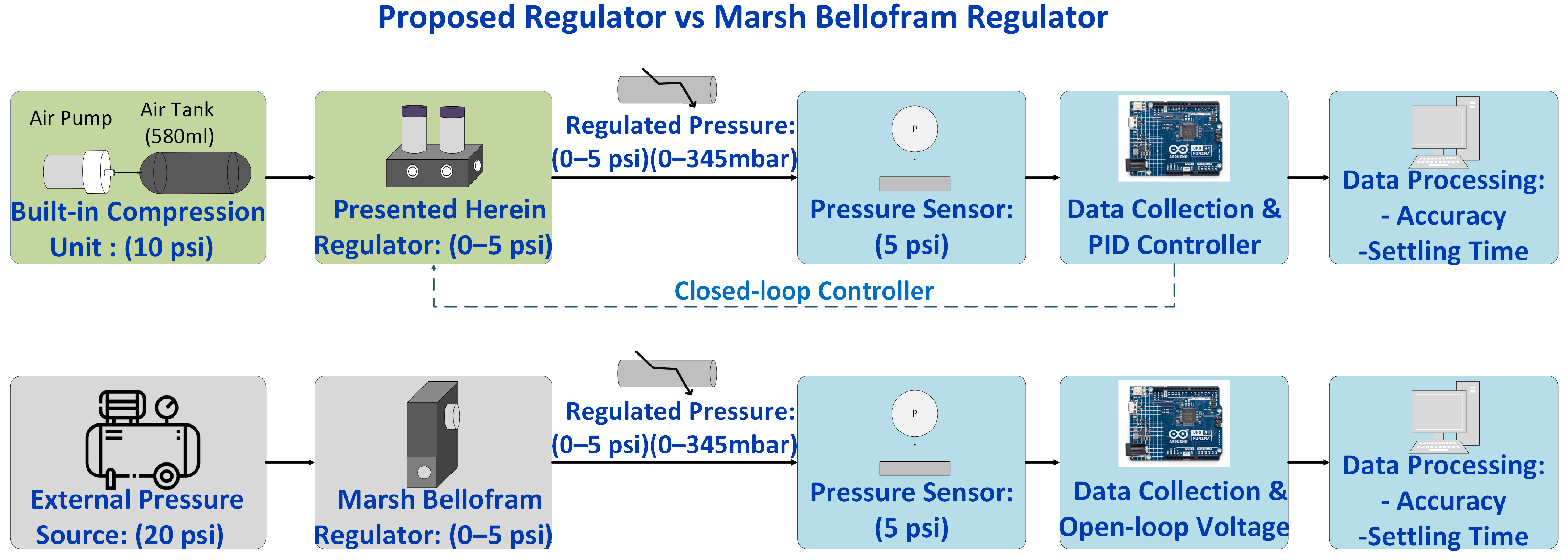
The performance of the pressure regulator presented herein is compared with the commercial Marsh Bellofram pressure regulator (T20002KSTNF05DF00500, Marsh Bellofram, Newell, WV, USA). The procedures followed to conduct this comparison test are presented in Figure 11. The green blocks correspond to the presented pressure regulator, supplied with a 10 psi pressure source from a built-in compression unit. Our regulator is controlled by a PID controller that regulates the two valves in a closed-loop system according to the set pressure signal provided by the Arduino. The gray blocks correspond to the commercial Marsh Bellofram regulator, supplied with 20 psi from an external pressure source. In this case, the Arduino provides the set pressure signal, where the commercial regulator operates in an open-loop mode to reach the target pressure. The blue blocks indicate the common procedures for both regulators. Thus, both devices are evaluated under the same conditions. The only exceptions are the inherent control characteristics of each pressure regulator and the pressure supply, since the commercial regulator requires a minimum of 20 psi.
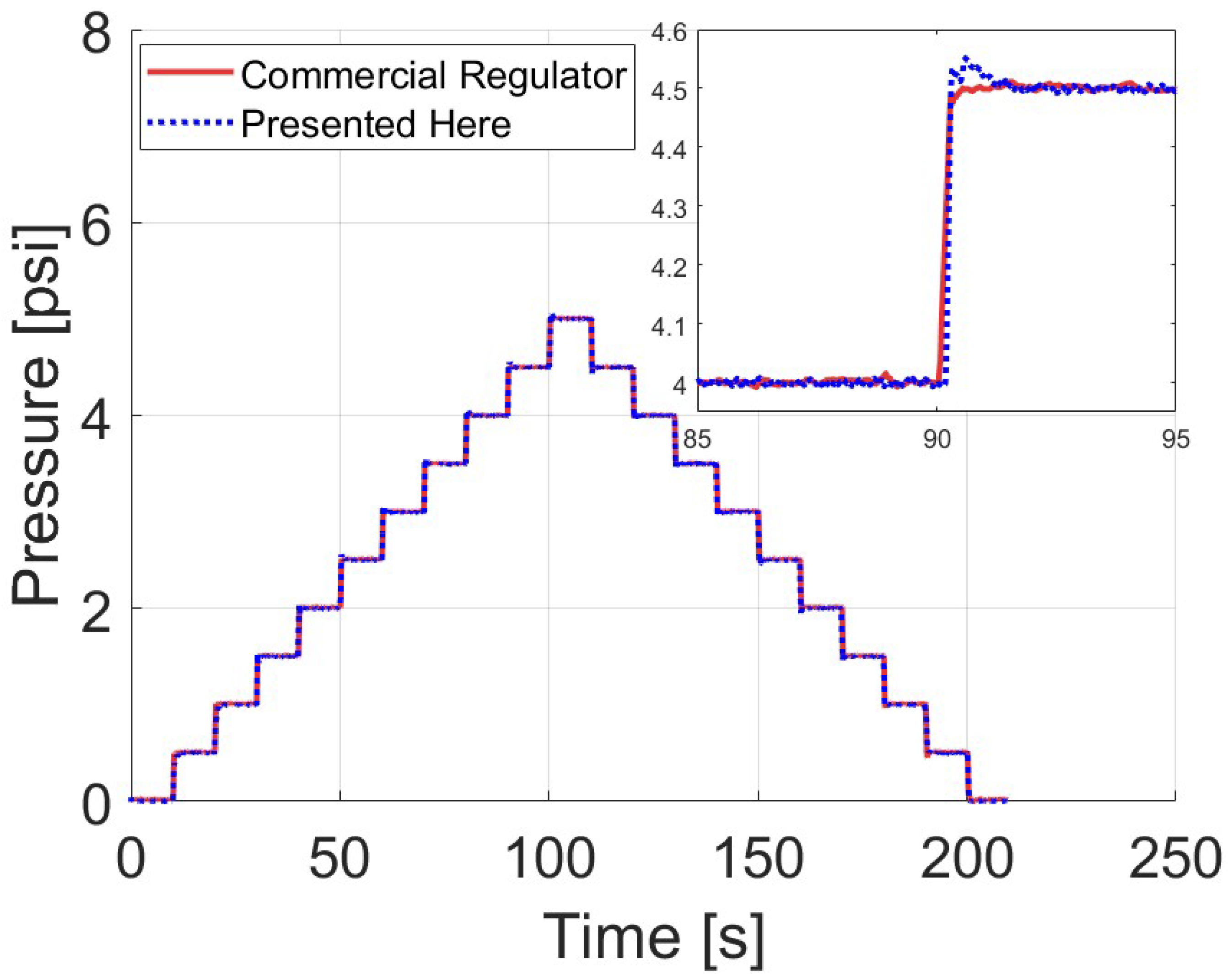
Figure 12 illustrates the dynamic response of both regulators at the same pressure levels from 0 to 5 psi previously mentioned in Section 4. The two systems—the one herein presented and the commercial system—show similar responses. The main discrepancy noticed in Figure 12 is an overshoot of less than 15% exhibited by the system presented herein. Nevertheless, adjusting the gain values can reduce the overshoot, but this will result in slower settling times. The performance of the commercial system is similarly assessed by computing the average standard deviation across the pressure levels. After 10 trials, the overall average standard deviation is approximately 0.005 psi. Therefore, the accuracy range defined by twice the standard deviation (±2 σ ) is ±0.01 psi, which matches the accuracy of the regulator presented here. This proves that our developed pressure regulator exhibits comparable performance to the commercial regulator, except at 0.5 psi, where the commercial regulator shows better consistency.
Similarly to Table 1, Table 2 summarizes the settling times for the commercial regulator following the same procedure. Ten trials are conducted instead of twenty. The regulator presented here achieves faster settling times at every pressure level except at 1 psi, where the commercial pump exhibits better repeatability at the low pressure level.
Table 3 compares the characteristics of both regulators. The accuracy of the two regulators is nearly identical. The commercial regulator achieves better stability at only a low pressure level of 0.5 psi. In contrast, our regulator exhibits a faster settling time by 100 ms, is more compact, and, most importantly, is affordable. Moreover, active microfluidic applications require, most importantly, a fast settling time rather than high accuracy and stability. In summary, the commercial regulator provides reliable performance but is tailored mainly for industrial applications. Our regulator is optimized for active microfluidic applications and is cost-effective.
The customizable pressure pump proposed herein combines the pressure regulator with the compression unit. Table 4 compares the characteristics of the pump presented herein to those of commercial pumps (Fluigent MFCTMS, Elveflow OB1TM) and open-pressure pumps. While other pumps have at least two channels, this work initially focuses on only one channel. The developed pump is adaptive and can be upgraded to accommodate more channels based on the user’s specifications. The results in Table 4 highlight that the pump presented here can provide performance nearly equivalent to that of commercial pumps but at a significantly lower price. Compared to open-source pressure pumps, our developed system not only provides an affordable price but also a much faster settling time, making it more suitable for active microfluidic applications. These features, along with its independence from an external pressure source to operate, enable our pump to be a strong alternative competitor to existing pumps.

6. Conclusions

In conclusion, the pressure pump presented herein overcomes the constraints of current commercial and open-source models by employing different techniques. The actuation method uses two solenoid valves controlled by a PID controller rather than utilizing commercial pressure regulators, which are expensive and mainly designed for industrial applications. In addition, the regulator is combined with an onboard compression system. This eliminates the need for an external pressure source, which is beneficial in environments with limited infrastructure. However, the system emits more noise and heat. The novel pressure pump is characterized to confirm its satisfactory performance. It offers stable and precise pressure control with an accuracy of ±0.01 psi (±0.7 mbar) from the desired pressure, which is desirable for passive microfluidic applications. It also provides fast settling times of less than 92 ms, making it suitable for active applications. In addition, the proposed pressure pump is cost-efficient, compact, and customizable. Finally, the easy-to-replicate pump presented here enhances the adaptability of pressure control technology across a wider range of users and applications, thereby making microfluidics more accessible.

7. Future Work

Our future work will focus on implementing further improvements and addressing current limitations. We will upgrade the pump to host multiple outputs. This will be conducted by integrating more pressure regulators, based on the design presented herein, and updating the control system code. However, the air pump’s capacity must be verified to determine whether it can handle multiple outputs or needs to be replaced with a more powerful air pump. Further enhancements can be made by reducing the noise and heat generated by onboard compression. In addition, investigating the factors causing the pressure regulator’s instability at pressures below 1 psi and optimizing its performance could be an interesting area for future work. Finally, the portability of the system can be improved by using a battery instead of utilizing an external power source.

Supplementary Materials

The following supporting information can be downloaded at https://www.mdpi.com/article/10.3390/act14120593/s1, Figure S1: Prototype of the assembled pressure pump before housing; Figure S2: Graph showing the variation of the air flow rate through the proportional solenoid valves with respect to the applied current; File S1: build instructions.

Author Contributions

Conceptualization, M.H.; methodology, M.H. and M.Z.; software, M.Z.; validation, M.Z. and R.M.; formal analysis, M.Z.; investigation, M.Z.; resources, M.H.; data curation, M.Z.; writing—original draft preparation, M.Z. and R.M.; writing—review and editing, M.Z., M.H., and S.K.; visualization, M.Z.; supervision, M.H.; project administration, M.H.; funding acquisition, M.H. and S.K. All authors have read and agreed to the published version of the manuscript.

Funding

This research is funded by Québec’s “Bourses créneaux d’expertise” and the Natural Science and Engineering Research Council of Canada (NSERC, RGPIN-2024-04714).

Institutional Review Board Statement

Not applicable.

Informed Consent Statement

Not applicable.

Data Availability Statement

The original contributions presented in this study are included in the article and Supplementary Material. Further inquiries can be directed to the corresponding author.

Conflicts of Interest

The authors declare no conflicts of interest.

References

  1. Niculescu, A.G.; Chircov, C.; Bîrcă, A.C.; Grumezescu, A.M. Fabrication and applications of microfluidic devices: A review. Int. J. Mol. Sci. 2021, 22, 2011. [Google Scholar] [CrossRef]
  2. Gharib, G.; Bütün, İ.; Muganlı, Z.; Kozalak, G.; Namlı, İ.; Sarraf, S.S.; Ahmadi, V.E.; Toyran, E.; Van Wijnen, A.J.; Koşar, A. Biomedical applications of microfluidic devices: A review. Biosensors 2022, 12, 1023. [Google Scholar] [CrossRef]
  3. Ferreira, M.; Carvalho, V.; Ribeiro, J.; Lima, R.A.; Teixeira, S.; Pinho, D. Advances in microfluidic systems and numerical modeling in biomedical applications: A review. Micromachines 2024, 15, 873. [Google Scholar] [CrossRef]
  4. Gao, R.Z.; Ren, C.L. Synergizing microfluidics with soft robotics: A perspective on miniaturization and future directions. Biomicrofluidics 2021, 15, 011302. [Google Scholar] [CrossRef]
  5. Xu, J.; Wu, T.; Zhang, Y. Soft microrobots in microfluidic applications. Biomed. Mater. Devices 2023, 1, 1028–1034. [Google Scholar] [CrossRef]
  6. Kang, M.; Yeo, W.H. Advances in energy harvesting technologies for wearable devices. Micromachines 2024, 15, 884. [Google Scholar] [CrossRef] [PubMed]
  7. Dudek, M.; Ullaland, H.S.; Wehrle, A.; Øye, G. Microfluidic testing of flocculants for produced water treatment: Comparison with other methodologies. Water Res. X 2020, 9, 100073. [Google Scholar] [CrossRef]
  8. Wang, T.; Yu, C.; Xie, X. Microfluidics for environmental applications. In Microfluidics in Biotechnology; Springer: Berlin/Heidelberg, Germany, 2020; pp. 267–290. [Google Scholar]
  9. Aryal, P.; Hefner, C.; Martinez, B.; Henry, C.S. Microfluidics in environmental analysis: Advancements, challenges, and future prospects for rapid and efficient monitoring. Lab Chip 2024, 24, 1175–1206. [Google Scholar] [CrossRef] [PubMed]
  10. Wong, W.D.; Majnis, M.F.; Lai, C.W.; Sagadevan, S.; Julkapli, N.M. Precise control on water treatment by microfluidic marvels. J. Environ. Chem. Eng. 2024, 12, 113880. [Google Scholar] [CrossRef]
  11. Kim, H.S.; Weiss, T.L.; Thapa, H.R.; Devarenne, T.P.; Han, A. A microfluidic photobioreactor array demonstrating high-throughput screening for microalgal oil production. Lab Chip 2014, 14, 1415–1425. [Google Scholar] [CrossRef]
  12. Westerwalbesloh, C.; Brehl, C.; Weber, S.; Probst, C.; Widzgowski, J.; Grünberger, A.; Pfaff, C.; Nedbal, L.; Kohlheyer, D. A microfluidic photobioreactor for simultaneous observation and cultivation of single microalgal cells or cell aggregates. PLoS ONE 2019, 14, e0216093. [Google Scholar] [CrossRef]
  13. Chong, Z.Z.; Tan, S.H.; Gañán-Calvo, A.M.; Tor, S.B.; Loh, N.H.; Nguyen, N.T. Active droplet generation in microfluidics. Lab Chip 2016, 16, 35–58. [Google Scholar] [CrossRef]
  14. Zhu, P.; Wang, L. Passive and active droplet generation with microfluidics: A review. Lab Chip 2017, 17, 34–75. [Google Scholar] [CrossRef]
  15. Shi, N.; Mohibullah, M.; Easley, C.J. Active flow control and dynamic analysis in droplet microfluidics. Annu. Rev. Anal. Chem. 2021, 14, 133–153. [Google Scholar] [CrossRef]
  16. Hébert, M.; Huissoon, J.; Ren, C.L. A perspective of active microfluidic platforms as an enabling tool for applications in other fields. J. Micromech. Microeng. 2022, 32, 043001. [Google Scholar] [CrossRef]
  17. Song, Y.; Zhou, Y.; Zhang, K.; Fan, Z.; Zhang, F.; Wei, M. Microfluidic programmable strategies for channels and flow. Lab Chip 2024, 24, 4483–4513. [Google Scholar] [CrossRef]
  18. Fergola, A.; Ballesio, A.; Frascella, F.; Napione, L.; Cocuzza, M.; Marasso, S.L. Droplet Generation and Manipulation in Microfluidics: A Comprehensive Overview of Passive and Active Strategies. Biosensors 2025, 15, 345. [Google Scholar] [CrossRef] [PubMed]
  19. Crawford, D.; Smith, C.; Whyte, G. Image-based closed-loop feedback for highly mono-dispersed microdroplet production. Sci. Rep. 2017, 7, 10545. [Google Scholar] [CrossRef]
  20. Hébert, M.; Courtney, M.; Ren, C.L. Semi-automated on-demand control of individual droplets with a sample application to a drug screening assay. Lab Chip 2019, 19, 1490–1501. [Google Scholar] [CrossRef] [PubMed]
  21. Wu, M.; Gao, Y.; Ghaznavi, A.; Zhao, W.; Xu, J. AC electroosmosis micromixing on a lab-on-a-foil electric microfluidic device. Sens. Actuators B Chem. 2022, 359, 131611. [Google Scholar] [CrossRef]
  22. Sun, J.; Shi, Z.; Li, M.; Sha, J.; Zhong, M.; Chen, S.; Liu, X.; Jia, S. Numerical and experimental investigation of a magnetic micromixer under microwires and uniform magnetic field. J. Magn. Magn. Mater. 2022, 551, 169141. [Google Scholar] [CrossRef]
  23. Wang, Y.; Li, Z.; Li, D.; Chen, F.; Zhao, Q.; Qing, J.; Li, X.; Yang, C.; He, X.; Zhao, Y. A Double-Rotating Ferrofluid Vane Micropump with an Embedded Fixed Magnet. Actuators 2024, 13, 308. [Google Scholar] [CrossRef]
  24. Zhou, X.; Li, Z.; Han, B.; Guo, Q.; Qing, Z. Performance Comparison of Mechanical and Ferrofluidic Micropumps: Structural and Operational Perspectives. Actuators 2025, 14, 460. [Google Scholar] [CrossRef]
  25. Maddala, J.; Srinivasan, B.; Bithi, S.S.; Vanapalli, S.A.; Rengaswamy, R. Design of a model-based feedback controller for active sorting and synchronization of droplets in a microfluidic loop. AIChE J. 2012, 58, 2120–2130. [Google Scholar] [CrossRef]
  26. Hébert, M.; Baxter, W.; Huissoon, J.P.; Ren, C.L. A Quantitative study of the dynamic response of soft tubing for pressure-driven flow in a microfluidics context. Microfluid. Nanofluid. 2020, 24, 90. [Google Scholar] [CrossRef]
  27. Hébert, M.; Huissoon, J.P.; Ren, C.L. A silicone-based soft matrix nanocomposite strain-like sensor fabricated using Graphene and Silly Putty®. Sens. Actuators A Phys. 2020, 305, 111917. [Google Scholar] [CrossRef]
  28. Hébert, M.; Huissoon, J.; Ren, C.L. A quantitative study of the dynamic response of compliant microfluidic chips in a microfluidics context. J. Micromech. Microeng. 2022, 32, 085004. [Google Scholar] [CrossRef]
  29. Hébert, M.; Huissoon, J.P.; Ren, C.L. A novel approach to determining the hydrodynamic resistance of droplets in microchannels using active control and grey-box system identification. J. Micromech. Microeng. 2023, 33, 085005. [Google Scholar] [CrossRef]
  30. Moscato, S.; Sanalitro, D.; Stella, G.; Bucolo, M. Model Predictive Control framework for slug flow microfluidics processes. Control Eng. Pract. 2024, 148, 105944. [Google Scholar] [CrossRef]
  31. Nguyen, T.H.; Chen, X.; Sedighi, A.; Krull, U.J.; Ren, C.L. A droplet-based microfluidic platform for rapid immobilization of quantum dots on individual magnetic microbeads. Microfluid. Nanofluid. 2018, 22, 63. [Google Scholar] [CrossRef]
  32. Kieffer, C.A.; Ritty, S.; Boudot, T.; Petit, N.; Weber, J.; Le Nel, A. A high precision fluid handling system based on pressure actuation: Multi-inlets flow-rate control. In Proceedings of the 3rd European Conference on Microfluidics, Heidelberg, Germany, 8–10 December 2012. [Google Scholar]
  33. Xiang, J.; Cai, Z.; Zhang, Y.; Wang, W. A micro-cam actuated linear peristaltic pump for microfluidic applications. Sens. Actuators A Phys. 2016, 251, 20–25. [Google Scholar] [CrossRef]
  34. Behrens, M.R.; Fuller, H.C.; Swist, E.R.; Wu, J.; Islam, M.M.; Long, Z.; Ruder, W.C.; Steward, R., Jr. Open-source, 3D-printed peristaltic pumps for small volume point-of-care liquid handling. Sci. Rep. 2020, 10, 1543. [Google Scholar] [CrossRef] [PubMed]
  35. Uvarov, I.V.; Shlepakov, P.S.; Melenev, A.E.; Ma, K.; Svetovoy, V.B.; Krijnen, G.J. A peristaltic micropump based on the fast electrochemical actuator: Design, fabrication, and preliminary testing. Actuators 2021, 10, 62. [Google Scholar] [CrossRef]
  36. Iakovlev, A.P.; Erofeev, A.S.; Gorelkin, P.V. Novel pumping methods for microfluidic devices: A comprehensive review. Biosensors 2022, 12, 956. [Google Scholar] [CrossRef] [PubMed]
  37. Byun, C.K.; Abi-Samra, K.; Cho, Y.K.; Takayama, S. Pumps for microfluidic cell culture. Electrophoresis 2014, 35, 245–257. [Google Scholar] [CrossRef]
  38. Sullender, C.T.; Santorelli, A.; Richards, L.M.; Mannava, P.K.; Smith, C.; Dunn, A.K. Using pressure-driven flow systems to evaluate laser speckle contrast imaging. J. Biomed. Opt. 2023, 28, 036003. [Google Scholar] [CrossRef]
  39. Kong, D.S.; Thorsen, T.A.; Babb, J.; Wick, S.T.; Gam, J.J.; Weiss, R.; Carr, P.A. Open-source, community-driven microfluidics with Metafluidics. Nat. Biotechnol. 2017, 35, 523–529. [Google Scholar] [CrossRef]
  40. Gao, R.Z.; Hébert, M.; Huissoon, J.; Ren, C.L. μPump: An open-source pressure pump for precision fluid handling in microfluidics. HardwareX 2020, 7, e00096. [Google Scholar] [CrossRef] [PubMed]
  41. Filatov, N.A.; Denisov, I.A.; Evstrapov, A.A.; Bukatin, A.S. Open-source pressure controller based on compact electro-pneumatic regulators for droplet microfluidics applications. IEEE Trans. Instrum. Meas. 2022, 71, 4003910. [Google Scholar] [CrossRef]
  42. Ernits, M.; Reinsalu, O.; Kyritsakis, A.; Linko, V.; Zadin, V. Low-Cost, Open-Source, High-Precision Pressure Controller for Multi-Channel Microfluidics. Biosensors 2025, 15, 154. [Google Scholar] [CrossRef]
  43. Sanchez, H.S.; Chang, C.B. Open-source pneumatic pressure pump for drop-based microfluidic flow controls. Eng. Res. Express 2023, 5, 035014. [Google Scholar] [CrossRef] [PubMed]
  44. Watson, C.; Senyo, S. All-in-one automated microfluidics control system. HardwareX 2019, 5, e00063. [Google Scholar] [CrossRef]
  45. White, J.A.; Streets, A.M. Controller for microfluidic large-scale integration. HardwareX 2018, 3, 135–145. [Google Scholar] [CrossRef]
  46. Davis, J.J.; Padalino, M.; Kaplitz, A.S.; Murray, G.; Foster, S.W.; Maturano, J.; Grinias, J.P. Utility of low-cost, miniaturized peristaltic and Venturi pumps in droplet microfluidics. Anal. Chim. Acta 2021, 1151, 338230. [Google Scholar] [CrossRef] [PubMed]
  47. Richter, M.; Anheuer, D.; Wille, A.; Congar, Y.; Wackerle, M. Multistage Micropump System towards Vacuum Pressure. Actuators 2023, 12, 227. [Google Scholar] [CrossRef]
Figure 1. An overview of the hardware setup of the developed system, displaying the three main parts: the compression unit, regulator system, and control circuit.
Actuators 14 00593 g001
Figure 2. The limitations of existing pressure pumps and the solution proposed by this study.
Actuators 14 00593 g002
Figure 3. PCB designs integrating all electrical connections and signals between system components. Two boards interface using seven electrical wires.
Actuators 14 00593 g003
Figure 4. The final design of the pressure pump enclosed in a compact box, with a zoomed view showing the pressure sensor that provides feedback to the regulator system.
Actuators 14 00593 g004
Figure 5. Overview diagram of pressure regulator control system mechanism.
Actuators 14 00593 g005
Figure 6. Recommended ranges for the PID controller gains yielding stable performance.
Actuators 14 00593 g006
Figure 7. The Pareto front showing the trade-off between the settling time and accuracy for PID gain selections. Each marker represents a different set of gain values ( K p K i K d ). The blue markers indicate all PID gain values tested for their accuracy and settling time. The red marker indicate the selected gain values for the rest of the performance quantification.
Actuators 14 00593 g007
Figure 8. A root locus plot for the closed-loop system ( G p l a n t , G c t r l ) with poles remaining on the left-hand side of the s-plane, and current poles are shown by red X markers. The blue and green line indicate the location of each pole.
Actuators 14 00593 g008
Figure 9. The Bode plot for the system ( G p l a n t , G c t r l ) with a phase margin of 144° and a gain margin of infinity.
Actuators 14 00593 g009
Figure 10. (a) The dynamic response of the presented regulator across pressure levels from 0 to 5 psi, with an inset for the step change between 1.5 and 2.0 psi. (b) The mean error values for 500 sample points at each pressure between 1 and 5 psi for the 20 trials. The different marker colors indicate the different pressure setpoints. The dotted line indicates that all data points ±2 standard deviations lie within ±0.01 psi (0.7 mbar) of the set pressure.
Actuators 14 00593 g010
Figure 11. A test plan diagram illustrating the experimental procedures used to compare the pressure regulator presented herein with the commercial Marsh Bellofram regulator.
Actuators 14 00593 g011
Figure 12. A dynamic response comparison between the presented regulator and the Marsh Bellofram regulator, with an inset showing the step change between 4 and 4.5 psi.
Actuators 14 00593 g012
Table 1. Settling time values at each pressure level between 1 and 5 psi across 20 trials for the regulator presented here. Slower (higher) settling times are indicated in shades of red while faster (smaller) settling times are indicated in shades of green.
Pressure (psi)
Trial11.522.533.544.55Mean Settling Time (s)
10.9620.1050.0910.0860.0890.0740.0660.0720.0700.086
20.7530.1150.0930.0860.0820.0770.0720.0670.0680.082
30.7310.1110.0930.0950.1320.0690.0690.0760.0650.093
40.3820.1020.0960.0820.0770.0730.0770.0710.0750.077
50.5610.0920.0870.0790.0760.0730.0700.0680.0680.076
60.5450.1580.1640.0810.0800.0740.0710.0660.0660.080
70.9270.1340.0900.0960.0910.0850.0800.0770.0720.090
80.2250.1340.0960.0960.0910.0850.0800.0770.0720.091
91.0220.1250.0940.0850.0860.0860.0730.0760.0650.086
100.0950.1120.0890.0850.0810.0760.0660.0710.0680.081
110.7570.1160.0930.0840.0760.0740.0680.0640.0610.076
120.1930.1090.1570.0820.0810.0750.0720.0680.0650.081
130.6510.1000.0980.0920.0780.0750.0700.0670.0650.078
140.5620.1770.0900.0790.0750.0700.0620.0920.0710.079
150.6080.1630.0960.0820.0750.0750.0700.0660.0660.075
160.5760.1690.1440.0880.0790.0760.0640.0670.0640.079
170.5650.0840.0830.1490.0720.0620.0660.0630.0620.072
180.5710.1640.0770.0780.0730.0710.0680.0570.0610.073
190.6110.1670.0770.1460.0740.0690.0600.0630.0610.074
200.5350.1620.0870.1530.0720.0630.0600.0630.0600.072
Overall Mean Settling time ± 2 σ  : 0.08 ± 0.012 s (80 ± 12 ms)
Table 2. Settling time values at each pressure level between 1 and 5 psi across 10 trials for the commercial regulator (T20002KSTNF05DF00500, Marsh Bellofram, Newell, WV, USA). Slower (higher) settling times are indicated in shades of red while faster (smaller) settling times are indicated in shades of green.
Pressure (psi)
Trial11.522.533.544.55Mean Settling Time (s)
10.2440.2230.2100.2780.1870.1770.1670.1550.1470.199
20.2410.2250.2670.1990.1870.1780.2160.1560.1440.201
30.2350.2220.2090.1950.1920.1810.1660.2060.1450.195
40.2360.2210.2150.2020.1890.1780.1630.1570.1390.189
50.2330.2260.2100.1950.1920.1750.1630.1610.1480.189
60.2320.2250.2080.2010.2160.1760.1610.1600.1430.191
70.2240.2140.2050.2160.1800.1680.1620.1000.1440.179
80.2300.2170.2070.1960.1810.1690.1550.1030.1380.177
90.2260.2170.1990.1920.1820.1700.1550.1470.1400.181
100.2550.2380.2280.2130.2070.1910.1830.1750.1650.206
Overall Mean Settling time ± 2 σ  : 0.191 ± 0.019 s (191 ± 19 ms)
Table 3. Comparison of our pressure regulator’s characteristics with the commercial regulator (T20002KSTNF05DF00500, Marsh Bellofram, Newell, WV, USA).
Accuracy
(psi/F.S%)
Settling Time
(ms)
Weight and Volume
(kg/cm3)
Cost
(USD)
Presented Here0.01/0.280 ± 120.3/120250
Marsh Bellofram0.01/0.2191 ± 191.35/4031000
Table 4. Comparison of our pressure pump specifications with existing pressure pumps.
PumpPressure Range
(psi)
Accuracy
(psi/% F.S.)
Settling Time
(ms)
Number of
Channels
Cost
(USD)
Presented
Here
1–50.01/0.2921650
Fluigent
MFCS
0–150.03/0.25100410,000
Elveflow
OB1
0–30.00045/0.0155026000
Open-source
µpump [40]
0–300.027/0.09200043000
Open-source
Sanchez et al. [43]
1–100.016/0.16160042400
Disclaimer/Publisher’s Note: The statements, opinions and data contained in all publications are solely those of the individual author(s) and contributor(s) and not of MDPI and/or the editor(s). MDPI and/or the editor(s) disclaim responsibility for any injury to people or property resulting from any ideas, methods, instructions or products referred to in the content.