Article

Robust Attitude Stabilization of Rigid Bodies Based on Control Lyapunov Function: Experimental Verification on a Quadrotor Testbed

1
Department of Robotics and Mechatronics, Tokyo Denki University, Tokyo 120-8551, Japan
2
Department of Electrical Engineering, Tokyo University of Science, Tokyo 125-8585, Japan
*
Author to whom correspondence should be addressed.
Actuators 2025, 14(10), 509; https://doi.org/10.3390/act14100509
Submission received: 30 August 2025 / Revised: 11 October 2025 / Accepted: 15 October 2025 / Published: 20 October 2025
(This article belongs to the Special Issue Modeling and Nonlinear Control for Complex MIMO Mechatronic Systems)

Abstract

The robust stabilization of the attitude of quadrotors with respect to disturbance torques is a fundamental and crucial control problem in many unmanned aerial vehicle (UAV) applications. For this problem, a control Lyapunov function (CLF)-based robust adaptive control was previously proposed by the authors, and its effectiveness was confirmed through numerical simulations. In this article, we tackle the experimental verification of this controller. We first construct a quadrotor testbed equipped with the self-developed flight controller. Then, we implement the proposed robust adaptive controller and perform flight experiments. According to the results of comparative experiments using a PID-type controller and a non-robust controller, we demonstrate the effectiveness of the proposed controller.

1. Introduction

Over the past two decades, the importance of unmanned aerial vehicles (UAVs) has increased significantly in various fields, including logistics, agriculture, infrastructure inspection, and disaster response [1]. Specifically, quadrotor UAVs are widely utilized. In the actual operations of quadrotors in such applications, stable flight is required in the presence of wind gusts, payload changes, and other external perturbations. Since the attitude dynamics of quadrotors are sensitive to disturbance torques, robust attitude stabilization/trajectory tracking control is a fundamental and essential problem in actual applications.
Since the attitude dynamics of quadrotors are nonlinear, numerous disturbance suppression control methods based on nonlinear control theory have been actively proposed (see e.g., [2,3] and references therein). Among them, disturbance observer (DOB)-based control [4,5,6,7,8], sliding mode control (SMC) [9,10,11], and nonlinear model predictive control (NMPC) [12,13,14] have been extensively studied. Although the effectiveness of these methods has been verified through both simulations and experiments, several points need to be considered when applying them to real quadrotors. Specifically, MPC is computationally intensive and must be implemented with sufficient computational resources. Furthermore, DOB-based methods require an accurate model of the system to estimate the disturbance. Sliding mode control may cause a chattering phenomenon.
Among the various nonlinear control methods, the control Lyapunov function (CLF)-based controller design is one of the most flexible approaches for achieving robust control [15,16]. A key advantage of CLF is that it offers a unified framework for designing various types of nonlinear controllers, including adaptive control [17], disturbance cancellation/attenuation control [18,19], and trajectory tracking control [19]. Notably, the concept of the input-to-state stability (ISS) and input-to-state stability control Lyapunov function (ISS-CLF) provides a powerful tool for disturbance attenuation control of nonlinear systems. Moreover, CLF-based adaptive control is also an effective method for dealing with system uncertainties.
To achieve robust attitude stabilization of quadrotors based on the CLF, a unit quaternion-based adaptive controller is proposed in [20]. This controller ensures robustness against parameter errors in the quadrotor, and numerical simulations have confirmed its effectiveness. Subsequently, this controller is extended to a robust adaptive controller by combining ISS-CLF to ensure robustness against disturbance torques [21]. As discussed in [21], the combination of adaptive control and disturbance attenuation by ISS is quite effective in achieving robust attitude stabilization. This is because the constant term of disturbances (containing parameter uncertainties) is compensated by adaptive parameter estimation, while the time-varying term is treated by disturbance attenuation based on the ISS. Another advantage of this controller is that, unlike MPC, the numerical calculation cost is very low and can be easily implemented on the microcontroller installed in flight controllers. However, the effectiveness of this controller has only been confirmed through numerical simulations and has not yet been implemented on actual quadrotors.
Based on the backgrounds mentioned above, the objective of this article is to confirm the effectiveness of the controller proposed in [21] through experiments utilizing an actual quadrotor. The contributions of this article are as follows:
  • We construct a quadrotor testbed integrating a self-developed flight controller to implement the proposed controller.
  • Through real-time flight experiments, we confirm that the proposed controller can achieve attitude stabilization.
  • To validate the importance of disturbance attenuation, we also conduct comparative experiments using a PID-type controller and a non-robust (i.e., without disturbance attenuation) controller.
The remainder of this article is organized as follows: In Section 2, we briefly introduce the basic definitions and results on disturbance attenuation control based on ISS. Section 3 is devoted to the formulation of the problem considered in this article. Then, we introduce the robust adaptive controller proposed in [21] in Section 4 and develop a quadrotor testbed in Section 5. The validation experiments on the developed quadrotor are presented in Section 6. Finally, a brief conclusion is provided in Section 7.

Notation

Let R and R n be the set of real numbers and the n-dimensional real vector space, respectively. The n × n identity matrix and the n × m zero matrix are denoted by I n and O n × m , respectively. We employ the following notations of comparison functions [22]:
  • A continuous function α : [ 0 , a ) [ 0 , ) is said to belong to class K ( α K ) if it is strictly increasing and α ( 0 ) = 0 . A function α K is said to belong to class K ( α K ) if a = and α ( r ) ( r ) .
  • A continuous function β : [ 0 , a ) × [ 0 , ) [ 0 , ) is said to belong to class KL ( α KL ) if, for each fixed s, the mapping β ( r , s ) belongs to class K with respect to r, and for each fixed r, the mapping β ( r , s ) is decreasing with respect to s and β ( r , s ) 0 ( s ) .

2. Input-to-State Stability (ISS) and ISS Control Lyapunov Function (ISS-CLF) for Nonlinear Systems [19]

In this section, we consider the following input-affine nonlinear system:
x ˙ = f ( x ) + g ( x ) u + h ( x ) d ,
where x R n is the state, u R m is the control input, and d R l is the disturbance. We assume that the mappings f : R n R n , g : R n R n × m , h : R n R n × l are locally Lipschitz continuous and f ( 0 ) = 0 . The solution of system (1) (with an initial condition x ( 0 ) = x 0 and a state feedback u = k ( x ) ) is denoted by x ( t ) .
To consider robust stabilization of the origin x = 0 of system (1) subject to disturbance d, we introduce the concept of input-to-state stability (ISS), defined as follows:
Definition 1
(ISS). A continuous state feedback controller u = k ( x ) said to input-to-state stabilize the origin of system (1) if there exist β KL and χ K such that
x ( t ) β ( | x ( 0 ) | , t ) + χ sup 0 τ t d ( τ ) , t 0 .
Remark 1.
The class K function χ in (2) characterizes the performance of disturbance attenuation and is called the ISS gain.
Definition 2
(ISS-CLF). A C 1 differentiable function V : R n R is said to be an input-to-state stable control Lyapunov function (ISS-CLF) for system (1) if the following conditions hold:
(A1) 
V is proper, i.e., the sublevel set { x R n V ( x ) L } is compact for every L > 0 ;
(A2) 
V is positive definite, i.e., V ( 0 ) = 0 and V ( x ) > 0 , x 0 ;
(A3) 
there exist a class K function ρ such that
x ρ ( d ) inf u R m L f V ( x ) + L g V ( x ) u + L h V ( x ) d < 0 ,
where L f V ( x ) , L g V ( x ) , and L h V ( x ) are defined as follows:
L f V ( x ) : = V x f ( x ) , L g V ( x ) : = V x g ( x ) , L h V ( x ) : = V x h ( x ) .
Theorem 1.
Let V ( x ) be an ISS-CLF for system (1). Then, the following state feedback controller input-to-state stabilizes the origin x = 0 of (1):
u = k ( x ) : = p ( x ) ( L g V ) ( x ) ,
p ( x ) : = ω ( x ) + ω 2 ( x ) + L g V ( x ) 4 L g V 2 ( L g V 0 ) 0 ( L g ˜ V = 0 ) ,
ω ( x ) : = L f V ( x ) + L h V ( x ) ρ 1 ( x ) ,
where ρ K satisfies condition (3).

3. Problem Formulation

In this paper, we consider the attitude control of a standard quadrotor UAV, as shown in Figure 1, where A = { e 1 b , e 2 b , e 3 b } and B = { e 1 i , e 2 i , e 3 i } are the world frame and the body-fixed frame, respectively.
An attitude of a rigid body (quadrotor) is represented as an element of the SO(3), defined as follows [23]:
SO ( 3 ) : = { R R 3 × 3 R R = I 3 , det R = 1 } ,
where det R is the determinant of R. The attitude dynamics of the quadrotor are given as the following control system on SO ( 3 ) × R 3 [24]:
R ˙ = R S ( Ω ) Ω ˙ = J 1 ( Ω × J Ω ) + J 1 τ + J 1 d ,
where Ω = ( Ω 1 , Ω 2 , Ω 3 ) R 3 is the angular velocity in the body-fixed frame, J = diag ( J θ , J ψ , J ψ ) is the inertia matrix, and ( θ , ϕ , ψ ) are roll–pitch–yaw angles (ZYX-Euler angles) corresponding to the unit quaternion q and the rotation matrix R = R ( q ) . For the transformation among these representations, see, e.g., [23,24].
The vectors τ = ( τ 1 , τ 2 , τ 3 ) R 3 and d = ( d 1 , d 2 , d 3 ) R 3 represent input and disturbance torques, respectively. The desired equilibrium for attitude stabilization is ( R , Ω ) = ( I , 0 , 0 , 0 ) .
A unit quaternion q defined by
q = r 0 , r = r 0 , r 1 , r 2 , r 3 R 4 , q = r 0 2 + r r = 1 ,  
is also used to represent the attitude. For a given unit quaternion q S 3 : = { q R 4 | q = 1 } , the corresponding rotation matrix R SO ( 3 ) is given by
R = R ( q ) = I 3 + 2 r 0 S ( r ) + 2 ( S ( r ) ) 2 ,
where S ( r ) is a skew-symmetric matrix defined by
S ( r ) = 0 r 3 r 2 r 3 0 r 1 r 2 r 1 0 = 1 2 1 + tr R ( R R .
Remark 2.
Since S ( r ) = S ( r ) in (12), note that q and q = r 0 , r correspond to the same rotation matrix R, i.e., R ( q ) = R ( q ) holds.
According to (11) and (12), the attitude dynamics (9) can be transformed into the following unit quaternion-based representation [20]:
q ˙ = r ˙ 0 r ˙ = 1 2 r T r 0 I + S ( r ) Ω Ω ˙ = J 1 ( Ω × J Ω ) + J 1 τ + J 1 d .
The desired equilibrium for corresponding to ( R , Ω ) = ( I , 0 , 0 , 0 ) is given by
( q , Ω ) = ( ( 1 , 0 , 0 , 0 ) , 0 , 0 , 0 ) .
Remark 3.
As we can confirm by (11), there exists two unit quaternions q and q that correspond to a rotation matrix R. This is known as the double-covering property and causes the unwinding phenomenon, which leads to undesirable transitions in the global stabilization of the attitude. For the desired attitude I 3 SO ( 3 ) , the corresponding unit quaternions satisfying (11) are q = ( 1 , 0 , 0 , 0 ) and q = ( 1 , 0 , 0 , 0 ) . In this article, however, we only consider the latter unit quaternion as the desired attitude. Theoretically, this implies considering semi-global stabilization.
By defining the state variable x : = ( q , Ω ) and the control input u : = τ , we finally obtain the nonlinear system
x ˙ = f ( x ) + g ( x ) ( u + d ) ,
where
f ( x ) = 1 2 r T Ω 1 2 ( r 0 I + S ( r ) ) Ω J 1 ( Ω × J Ω ) , g ( x ) = h ( x ) = O 4 × 3 J 1 .
The objective of this paper is to apply an ISS-CLF-based robust attitude stabilizing controller proposed in [21], which input-to-state stabilizes (14) of system (15) to a self-developed quadrotor testbed, and we confirm its effectiveness through experiments.

4. Controller Design [21]

In this section, we introduce the robust attitude stabilizing controller proposed in [21].

4.1. ISS-CLF Design for System (15)

We first design a static state feedback u = k ( x ) which input-to-state stabilizes the desired equilibrium (14). To do so, we employ the following theorem:
Theorem 2.
Consider system (15) and the desired equilibrium (14). Then, the following V ( x ) is a ISS-TCLF:
V ( x ) = 2 α ( r 0 + 1 ) + β 2 ( Ω Γ r ) J ( Ω Γ r ) ,
where α , β > 0 are positive constants and Γ R R 3 × 3 is a positive definite symmetric matrix. Moreover, any class K function ρ satisfies condition (3).
According to (17) and (16), we can calculate L f V ( x ) and L g V ( x ) as follows:
L f V ( x ) = V x f ( x ) = α r Ω β 2 ( Ω Γ r ) J Γ ( r 0 I + S ( r ) ) Ω + β ( Ω Γ r ) ( Ω × J Ω ) , L g V ( x ) = V x g ( x ) = ( Ω Γ r ) J .
Then, by substituting (18) and any class K function ρ into (5), we can obtan the input-to-state stabilizing controller u = k ( x ) .

4.2. Extension to the Robust Adaptive Controller

This subsection introduces the adaptive compensation term to mitigate the effect of the disturbance. We suppose that the disturbance torque d ( t ) can be separated into
d ( t ) = d c o n s t + d ˜ ( t ) ,
where d c o n s t is the constant term and d ˜ ( t ) is the residual (time-varying) term. The basic idea here is to estimate d c o n s t by Lyapunov-based adaptive control and compensate the effect of d ˜ ( t ) by disturbance attenuation of input-to-stability stabilization. Let d ^ c o n s t be an estimate of d c o n s t . Then, the proposed adaptive controller is given by
u = k ( x ) d ^ c o n s t d ^ ˙ c o n s t = Λ L g V ( x ) ,
where k ( x ) is the input-to-state stabilizing controller designed in Section 4.1 and Λ = diag ( λ 1 , λ 2 , λ 3 ) is the adaptive gain matrix, with each diagonal element being positive.
Remark 4.
Note that the theoretical analysis and simulation results are provided in [21]. According to Theorem 3 in [21], the controller (20) input-to-state stabilizes the desired equilibrium (14) of system (15).
Remark 5.
It should be mentioned that when applying the proposed controller, we do not need to separate the disturbance as in (19) a priori, since the constant part is estimated and updated online.

5. Development of a Quadrotor Testbed

5.1. Configuration of the Quadcopter

To confirm the effectiveness of the proposed controller (20) by experiments, we develop the quadrotor testbed shown in Figure 2.
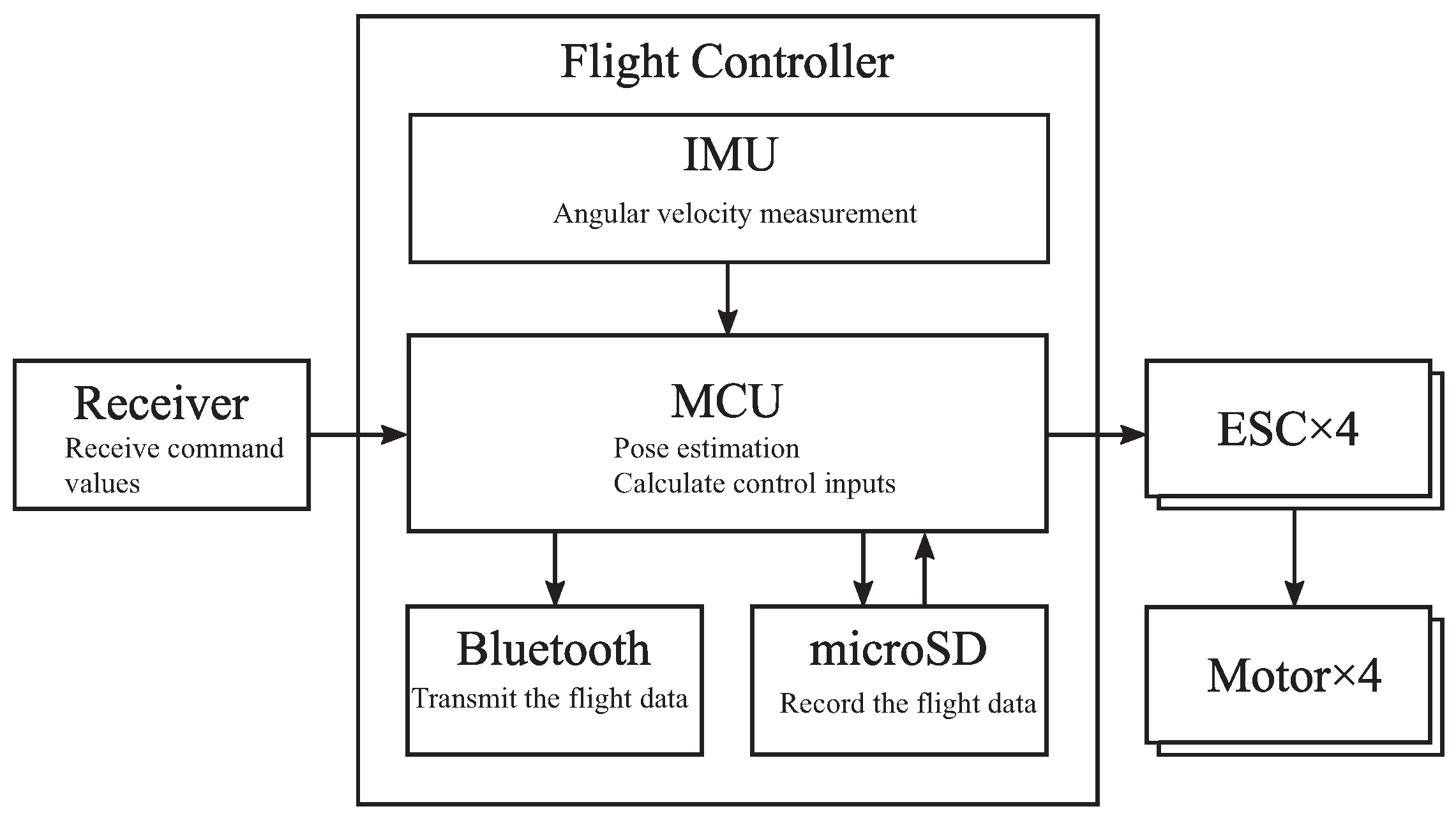
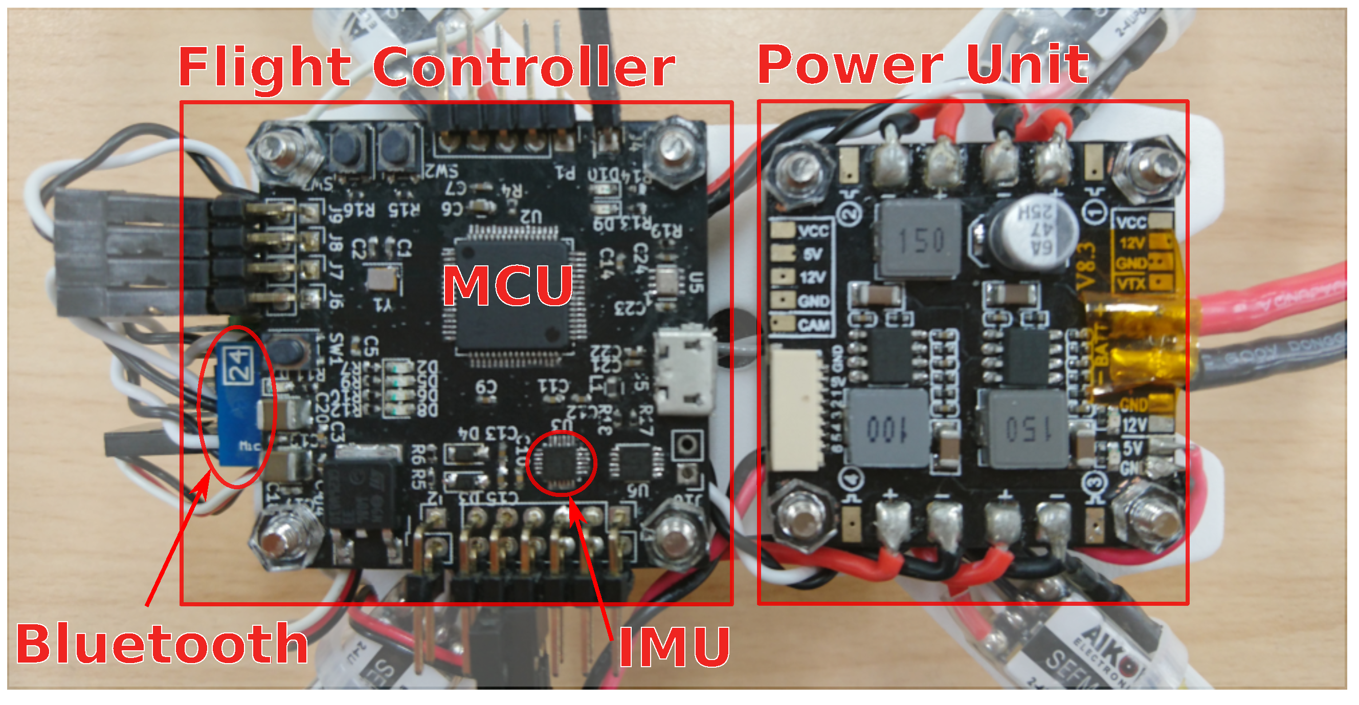
The hardware configuration of the quadcopter is depicted in Figure 3. The attitude of the quadrotor is measured and controlled by the flight controller shown in Figure 4. The flight controller is equipped with an inertial measurement unit (IMU) sensor that acquires three-axis acceleration and angular velocity. The attitude estimation and the calculation of the control input are performed by the microcontroller unit (MCU), which utilizes the STM32. The ESC (electric speed controller) is a component used to control the rotation speed of three-phase brushless motors. It controls each of the four motors according to the pulse width of the PWM signal output from the flight controller. In this experiment, the receiver also receives command values from the transmitter, such as the target thrust for the entire aircraft and which control law to use.
Figure 5 shows the UML of the software implemented in the flight controller. The angular velocity and acceleration are read from the IMU class, and the attitude angle is estimated using the Madgwick Filter class [25]. The control torque is determined by the Controller class from the acquired angular velocity and attitude angle and the command value of the SBUS class. The calculated control torque is passed to the ESCController class. This class converts the appropriate voltage into a PWM signal based on the previously identified relationship between rotor thrust and voltage and outputs it to the ESC. Additionally, the attitude angle, angular velocity, and control input are recorded onto the microSD card, and the recorded data is then transferred to a PC via Bluetooth.
The identified physical parameters of the quadrotor testbed are summarized in Table 1. We note that the rotational inertia J θ , J ϕ , and J ψ are identified by the bifilar suspension experiments [26]. The parameters κ 1 and κ 2 will be identified in the following subsection.

5.2. Conversion of Input Torque to a PWM Signal

The proposed control law provides an input torque, whereas the actual input to the quadrotor is a PWM command value for the ESC. Therefore, we convert the input torque into a PWM signal based on the relationship between propeller thrust and rotor rotation speed, as well as between rotor rotation speed and the pulse width of the PWM signal. It is generally known that the fan torque due to propeller thrust and air resistance is proportional to the square of the rotor rotational speed. More precisely, the relationship between the rotor speed w i ( i = 1 4 ) [ rpm ] , the total thrust of the four propellers f T [ N ] , and the input torque to the quadrotor τ = ( τ 1 , τ 2 , τ 3 ) [ Nm ] can be expressed as follows [27]:
f T τ 1 τ 2 τ 3 = κ 1 κ 1 κ 1 κ 1 0 l κ 1 0 l κ 1 l κ 1 0 l κ 1 0 κ 2 κ 2 κ 2 κ 2 w 1 2 w 2 2 w 3 2 w 4 2 ,
where κ 1 and κ 2 are coefficients that represent the thrust and torque characteristics of the propeller, respectively.
Based on the experiments utilizing the thrust stand RCbenchmark 1580 (Tyto Robotics, Gatineau, QC, Canada), we identified the values of κ 1 and κ 2 (see Table 1). Furthermore, the relationship between the rotor speed w i ( i = 1 , , 4 ) and the PWM signal pulse width P w [ μ s ] is also identified as follows:
P w = 0.001008   w i + 5.004
In the experiment, we determine the pulse width input to the ESC by using (21) and (22).

6. Experimental Verification

In this section, we confirm the effectiveness of the controller (20) through attitude stabilization experiments on the quadrotor testbed developed in Section 5.

6.1. Experimental Conditions

To compare the proposed controller and others under the same conditions, we consider additional PWM inputs as (pseudo) disturbances. We perform the following two experiments in this section:
Experiment 1.
Comparison with a PID-type controller.
In this experiment, we compare the performances of the controller (20) and the following PID-type controller:
  u p i d = ( u 1 , p i d , u 2 , p i d , u 3 , p i d ) , u i , p i d = K i , P 1 ( ω d i ω ) + K i , I 1 0 t ( ω d i ω i ) d τ + K D 1 ( ω ˙ d i ω i ˙ ) ( i = 1 , 2 , 3 ) ,   ω d i = K i , P 2 e i + K i , I 2 0 t e i d τ ( i = 1 , 2 , 3 ) ,
where ( e 1 , e 2 , e 3 ) = ( θ , ϕ , ψ ) .
Here we consider the experimental procedure depicted in Figure 6. After making the quadrotor hover, a PWM signal with a duty cycle of ± 0.4 is applied for 100 [ms]. Then, no disturbance is applied for 100 [ms], and finally, a PWM signal with a duty cycle of 0.4 is applied.
Experiment 2.
Evaluation of disturbance attenuation performance.
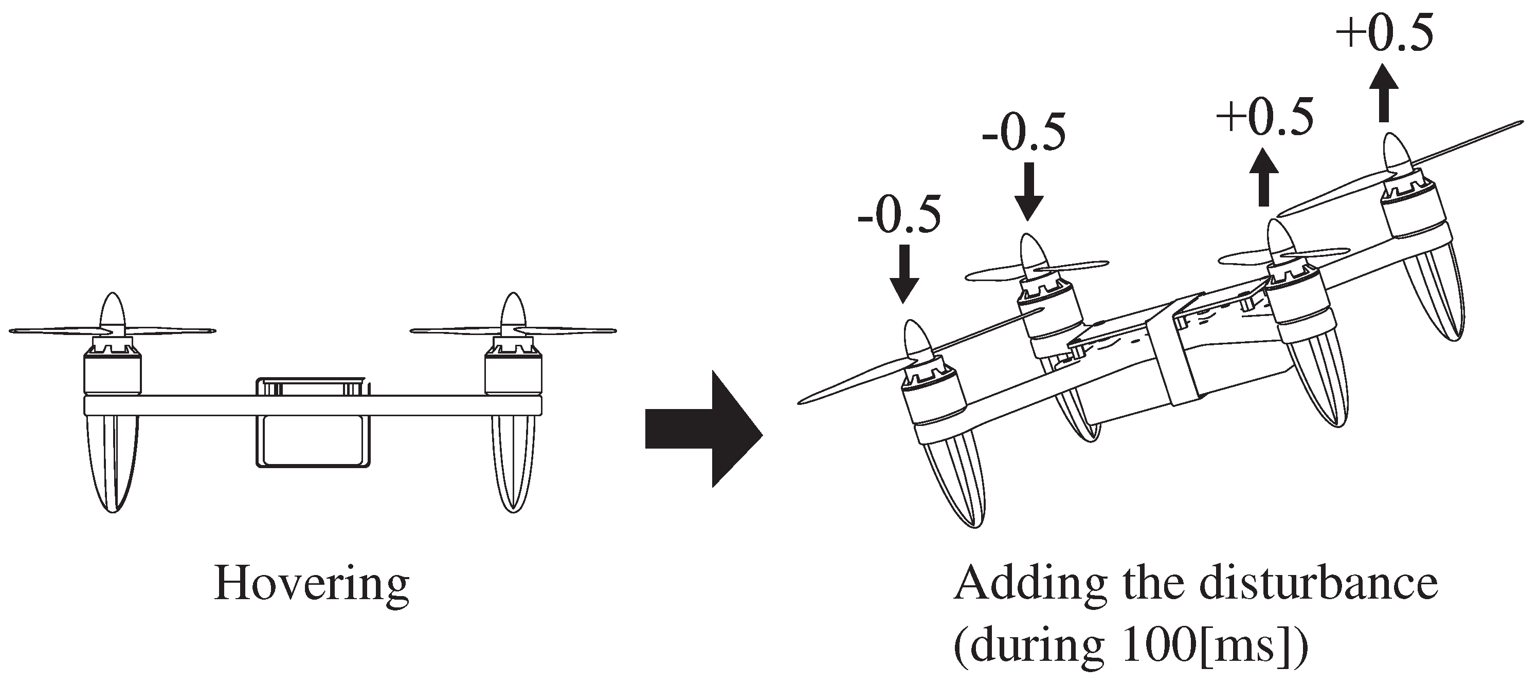
In this experiment, we compare the disturbance attenuation performance of the controller (20) with that of the controller without disturbance attenuation under the experimental procedure depicted in Figure 7.
After making the quadrotor hover, a PWM signal with a duty cycle of ± 0.5 is applied for 100 [ms]. As the controller without disturbance attenuation, we simply employ the controller (20) with ρ 0 (i.e., ω ( x ) = L f V ( x ) in (6)). Other control parameters are set to the same values as those in the controller (20).
In both experiments, we set the parameters of the CLF (17) as α = β = 0.26 and Γ = diag ( 30 , 30 , 50 ) . Moreover, we design the function ρ 1 in (6) as ρ 1 ( x ) = δ | r 0 + 1 | + Ω , where δ > 0 is a positive constant which is set to
δ = 0.12 ( Experiment 1 ) 0.5 ( Experiment 2 ) .
Finally, the adaptive gain matirix in (20) is set to Λ = diag ( 0.5 , 0.5 , 0.5 ) .
The parameters of the PID-type controller (23) utilized in Experiment 1 are set to
K 1 , P 1 = 0.001 , K 1 , I 1 = 3 × 10 5 , K 1 , D 1 = 1 × 10 7 , K 1 , P 2 = 2 , K 1 , I 1 = 0.001 , K 2 , P 1 = 0.001 , K 2 , I 1 = 3 × 10 5 , K 2 , D 1 = 1 × 10 7 , K 2 , P 2 = 2 , K 3 , I 1 = 0.001 , K 3 , P 1 = 0.0015 , K 3 , I 1 = 4 × 10 5 , K 3 , D 1 = 1 × 10 7 , K 3 , P 2 = 2 , K 3 , I 1 = 0.001 .
We note that the parameters in (25) were determined using the trial-and-error method.

6.2. Results of Experiment 1

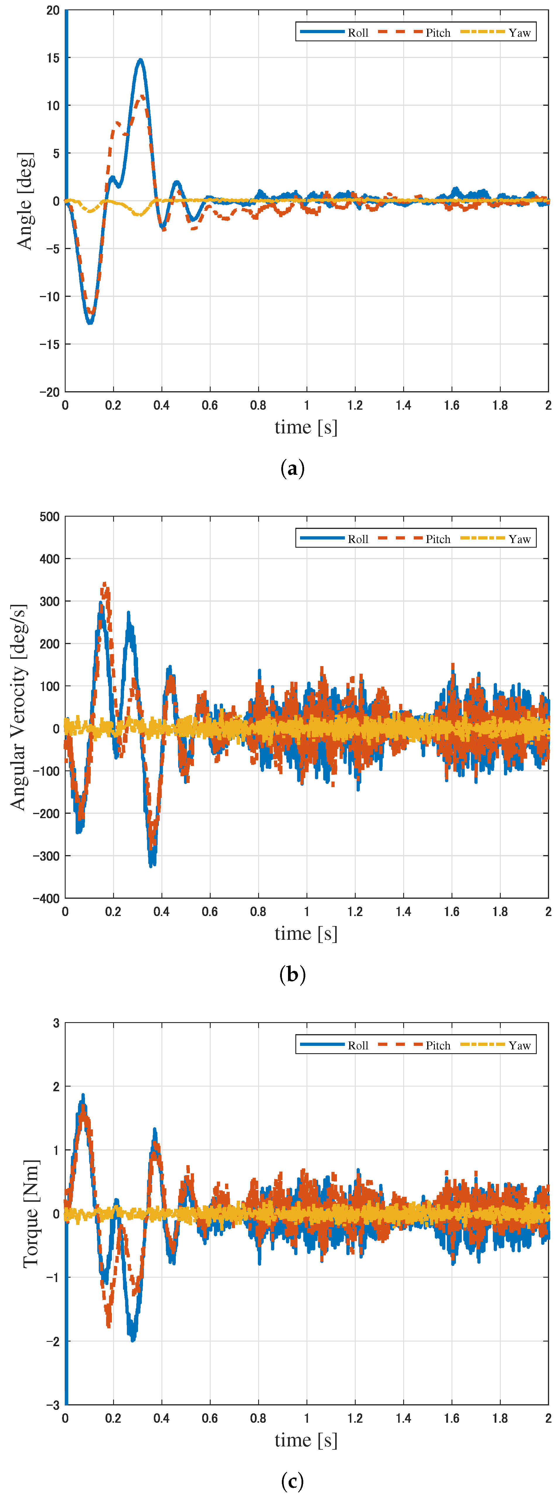
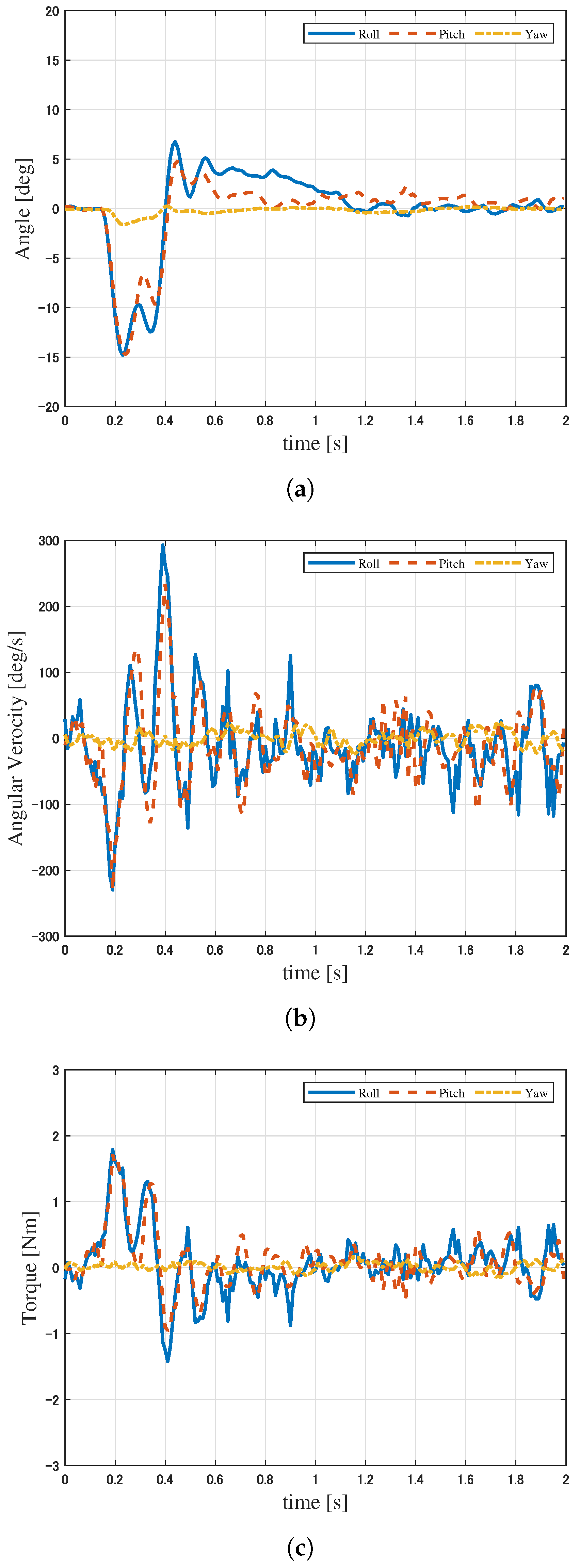
The experimental results of the controller (20) are summarized in Figure 8. We note that the disturbance is added at t = 0 [s] and t = 0.2 [s]. According to Figure 8a, we can confirm that each attitude angle converges to zero, indicating that the proposed controller successfully recovers the attitude after the disturbance is applied. Figure 8b,c shows that there are oscillations in the angular velocities and torques after attitude angles converge. This appears to be due to the relatively high-gain inputs being applied to suppress the effect of disturbances.
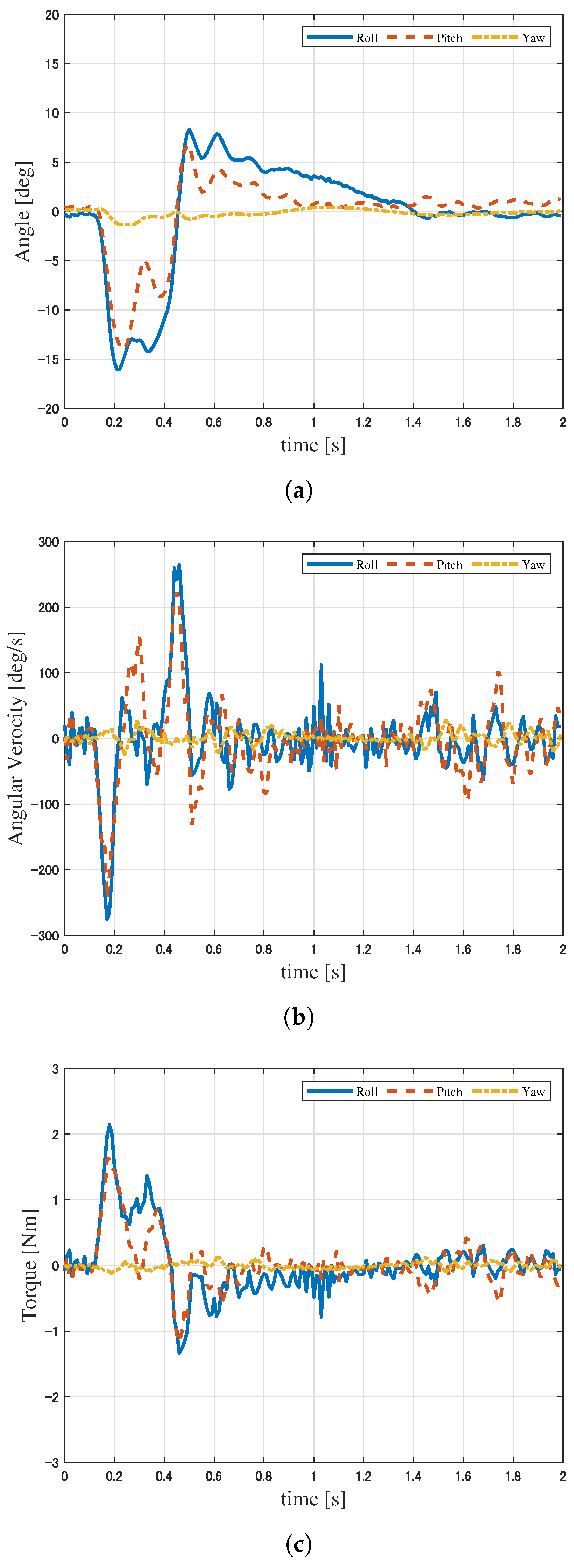
The experimental results with the PID-type controller (23) under the same conditions are shown in Figure 9. From Figure 9a, we can see that the attitude angles diverge after the disturbance is applied, i.e., the PID-type controller (23) fails to recover the attitude. As a result, the quadrotor crashes around t = 0.8 [s]. After the crash, the (estimated) torque looks like it changed, but the angular velocity converges to 0. Therefore, we can confirm the effectiveness of the proposed controller (20) for attitude stabilization, even in the presence of disturbances.

6.3. Results of Experiment 2

We show the experimental results of the proposed controller (20) in Figure 10. We note that the disturbance is added at t = 0 [s]. As in Experiment 1, we can observe that the proposed controller recovers the attitude after the disturbance is applied. To compare the disturbance attenuation performance, we also present the experimental results for the stabilizing controller without disturbance attenuation (i.e., the proposed controller (20) with ρ 0 ) in Figure 11.
Comparing Figure 10a and Figure 11a, we can see that the proposed controller suppresses the peak of the attitude angle fluctuation due to the disturbance around t = 0.2 [s] and t = 0.5 [s] and achieves faster convergence of the attitude angles. This is due to the proposed controller being relatively high-gain feedback. In fact, comparing Figure 10c with Figure 11c, we can confirm that the proposed controller provides relatively large input, specifically in the interval 0.4 t 1.2 . On the other hand, the input peak at t = 0.2 [s] is smaller than that of the controller without disturbance attenuation. This result indicates that the proposed controller responds more quickly to disturbances. Hence, we can confirm the effectiveness of the disturbance attenuation term of the proposed controller.

7. Conclusions

The objective of this article was to confirm the effectiveness of the robust adaptive controller (20), which was originally proposed in [21]. To do so, we first construct the quadrotor testbed integrating the self-developed flight controller. We then implemented the proposed controller on the flight controller and performed real-time flight experiments to demonstrate its effectiveness.
In Experiment 1, we confirmed that the proposed controller can stabilize the desired attitude even in the presence of the disturbance. Since the PID-type controller (23) fails to stabilize in the comparative experiment under the same conditions, we confirmed the superiority of the proposed controller. Then, we evaluated the performance of the disturbance attenuation in the proposed controller in Experiment 2. According to the comparative experiment of the proposed controller with the non-robust (without disturbance attenuation) one, we demonstrated that the proposed controller suppresses the effect of the disturbance and achieves faster attitude convergence.
Although the effectiveness of the proposed controller was partially verified, additional comparative experiments, including a statistical approach, are necessary for a more precise evaluation. Moreover, a discussion on effective performance metrics to evaluate disturbance attenuation performance is also essential. In the present paper, we employed the PWM disturbance for comparative experiments; additional validation experiments with other types of disturbances are also required. Particularly, robustness with respect to disturbance, which contains a constant term, such as a steady wind, should be demonstrated. Additionally, extending the proposed controller to trajectory tracking control and position control of the quadrotor is an important future research topic.

Author Contributions

Conceptualization, Y.S. and K.O.; methodology, Y.S. and K.O.; software, K.O.; validation, Y.S. and K.O.; formal analysis, Y.S. and K.O.; investigation, Y.S. and K.O.; data curation, K.O.; writing—original draft, Y.S. and K.O.; writing—review and editing, Y.S.; visualization, K.O.; supervision, Y.S.; project administration, Y.S.; funding acquisition, Y.S. All authors have read and agreed to the published version of the manuscript.

Funding

This study was partially supported by JSPS KAKENHI Grant Numbers JP20K14769 and JP25K07805.

Institutional Review Board Statement

Not applicable.

Informed Consent Statement

Not applicable.

Data Availability Statement

The raw data supporting the conclusions of this article will be made available by the authors upon request.

Conflicts of Interest

The authors declare no conflicts of interest.

References

  1. Nonami, K. Drone Technology, Cutting-Edge Drone Business, and Future Prospects. J. Robot. Mechatron. 2016, 28, 262–272. [Google Scholar] [CrossRef]
  2. Nascimento, T.P.; Saska, M. Position and attitude control of multi-rotor aerial vehicles: A survey. Annu. Rev. Control 2019, 48, 129–146. [Google Scholar] [CrossRef]
  3. Marshall, J.A.; Sun, W.; L’Afflitto, A. A survey of guidance, navigation, and control systems for autonomous multi-rotor small unmanned aerial systems. Annu. Rev. Control 2021, 52, 390–427. [Google Scholar] [CrossRef]
  4. Castillo, A.; Sanz, R.; Garcia, P.; Qiu, W.; Wang, H.; Xu, C. Disturbance observer-based quadrotor attitude tracking control for aggressive maneuvers. Control Eng. Pract. 2019, 82, 14–23. [Google Scholar] [CrossRef]
  5. Xie, W.; Yu, G.; Cabecinhas, D.; Cunha, R.; Silvestre, C. Global Saturated Tracking Control of a Quadcopter with Experimental Validation. IEEE Control Syst. Lett. 2021, 5, 169–174. [Google Scholar] [CrossRef]
  6. Azid, S.I.; Kumar, K.; Cirrincione, M.; Fagiolini, A. Robust Motion Control of Nonlinear Quadrotor Model with Wind Disturbance Observer. IEEE Access 2021, 9, 149164–149175. [Google Scholar] [CrossRef]
  7. Kazim, M.; Azar, A.T.; Koubaa, A.; Zaidi, A. Disturbance-Rejection-Based Optimized Robust Adaptive Controllers for UAVs. IEEE Syst. J. 2021, 15, 3097–3108. [Google Scholar] [CrossRef]
  8. Wang, F.; Gao, H.; Wang, K.; Zhou, C.; Zong, Q.; Hua, C. Disturbance Observer-Based Finite-Time Control Design for a Quadrotor UAV with External Disturbance. IEEE Trans. Aerosp. Electron. Syst. 2021, 57, 834–847. [Google Scholar] [CrossRef]
  9. Mechali, O.; Xu, L.; Huang, Y.; Shi, M.; Xie, X. Observer-based fixed-time continuous nonsingular terminal sliding mode control of quadrotor aircraft under uncertainties and disturbances for robust trajectory tracking: Theory and experiment. Control Eng. Pract. 2021, 111, 104806. [Google Scholar] [CrossRef]
  10. Shao, X.; Sun, G.; Yao, W.; Liu, J.; Wu, L. Adaptive Sliding Mode Control for Quadrotor UAVs with Input Saturation. IEEE/ASME Trans. Mechatron. 2022, 27, 1498–1509. [Google Scholar] [CrossRef]
  11. Lian, S.; Meng, W.; Lin, Z.; Shao, J.; Zheng, J.; Li, H. Adaptive Attitude Control of a Quadrotor Using Fast Nonsingular Terminal Sliding Mode. IEEE Trans. Ind. Electron. 2022, 6, 3769–3776. [Google Scholar] [CrossRef]
  12. Torrente, G.; Kaufmann, E.; Föhn, P.; Scaramuzza, D. Data-Driven MPC for Quadrotors. IEEE Robot. Autom. Lett. 2021, 6, 3769–3776. [Google Scholar] [CrossRef]
  13. Sun, S.; Romero, A.; Foehn, P.; Kaufmann, E.; Scaramuzza, D. A Comparative Study of Nonlinear MPC and Differential-Flatness-Based Control for Quadrotor Agile Flight. IEEE Trans. Robot. 2022, 38, 3357–3373. [Google Scholar] [CrossRef]
  14. Xu, Z.; Fan, L.; Qiu, W.; Wen, G.; He, Y. A Robust Disturbance-Rejection Controller Using Model Predictive Control for Quadrotor UAV in Tracking Aggressive Trajectory. Drones 2023, 7, 557. [Google Scholar] [CrossRef]
  15. Sontag, E.D. A ‘Universal’ Construction of Artstein’s Theorem on Nonlinear Stabilization. Syst. Control Lett. 1989, 13, 117–123. [Google Scholar] [CrossRef]
  16. Sepulchre, R.; Janković, M.; Kokotović, P.V. Constructive Nonlinear Control; Springer: London, UK, 1997. [Google Scholar]
  17. Krstić, M.; Kanellakopoulos, I.; Kokotović, P. Nonlinear and Adaptive Control Design; John Wiley and Sons: New York, NY, USA, 1995. [Google Scholar]
  18. Freeman, R.A.; Kokotović, P. Robust Nonlinear Control Design: State-Space and Lyapunov Techniques; Birkhäuser: Boston, MA, USA, 1996. [Google Scholar]
  19. Krstić, M.; Deng, H. Stabilization of Nonlinear Uncertain Systems; Springer: London, UK, 1998. [Google Scholar]
  20. Hatayama, T.; Nakamura, H. Discontinuous Adaptive Control of Attitude of Rigid Body by Using Minimum Projection Method. In Proceedings of the SICE Annual Conference 2014, Sapporo, Japan, 9–12 September 2014; pp. 1424–1429. [Google Scholar]
  21. Ohno, K.; Satoh, Y.; Nakamura, H.; Kato, K. Disturbance rejection control of rigid body attitude based on nonsmooth control Lyapunov function. In Proceedings of the 44th Annual Conference of the IEEE Industrial Electronics Society, Washington, DC, USA, 21–23 October 2018; pp. 2293–2298. [Google Scholar]
  22. Khalil, H.K. Nonlinear Systems, 3rd ed.; Prentice-Hall: Upper Saddle River, NJ, USA, 2002. [Google Scholar]
  23. Siciliano, B.; Sciavicco, L.; Villani, L.; Oriolo, G. Robotics: Modelling, Planning and Control; Springer: London, UK, 2010. [Google Scholar]
  24. Wie, B. Space Vehicle Dynamics and Control, 2nd ed.; American Institute of Aeronautics: Reston, VA, USA, 2008. [Google Scholar]
  25. Madgwick, S.O.H. An efficient orientation filter for inertial and inertial/magnetic sensor arrays. Rep. x-io Univ. Bristol (UK) 2010, 25, 763–775. [Google Scholar]
  26. Jardin, M.R.; Mueller, E.R. Optimized Measurements of UAV Mass Moment of Inertia with a Bifilar Pendulum. J. Aircr. 2009, 46, 763–775. [Google Scholar] [CrossRef]
  27. Nonami, K.; Kendoul, F.; Suzuki, S.; Wang, W.; Nakazawa, D. Autonomous Flying Robots: Unmanned Aerial Vehicles and Micro Aerial Vehicles; Springer: Tokyo, Japan, 2014. [Google Scholar]
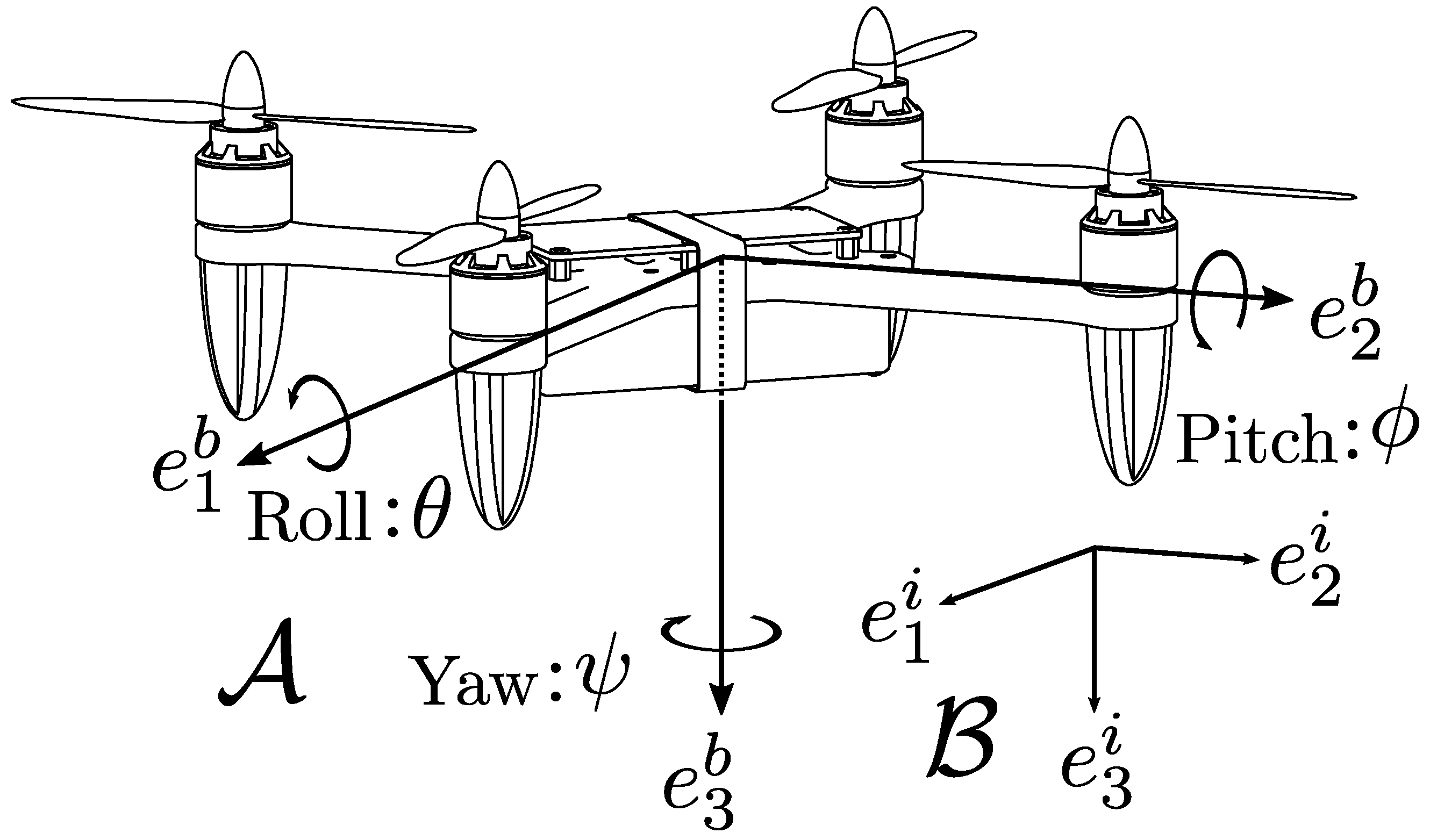
Figure 1. Quadrotor UAV.
Actuators 14 00509 g001
Figure 2. Developed quadrotor testbed.
Actuators 14 00509 g002
Figure 3. Hardware configuration of the quadcopter.
Actuators 14 00509 g003
Figure 4. Self-developed flight controller.
Actuators 14 00509 g004
Figure 5. UML of the software implemented in the flight controller.
Actuators 14 00509 g005
Figure 6. Procedure of Experiment 1.
Actuators 14 00509 g006
Figure 7. Procedure of Experiment 2.
Actuators 14 00509 g007
Figure 8. Experimental results with the controller (20) in Scenario 1: Euler angles (a); angular velocities (b); and input torques (c).
Actuators 14 00509 g008
Figure 9. Experimental results with the PID controller (23) in Scenario 1: Euler angles (a); angular velocities (b); and input torques (c).
Actuators 14 00509 g009
Figure 10. Experimental results with the controller (20) in Scenario 2: Euler angles (a); angular velocities (b); and input torques (c).
Actuators 14 00509 g010
Figure 11. Experimental results with the controller (20) without disturbance attenuation: Euler angles (a); angular velocities (b); and input torques (c).
Actuators 14 00509 g011
Table 1. Physical parameters of the developed quadrotor.
ParameterExplanationValue
l [m]Arm length 0.115
m [kg]Mass of the quadrotor 0.308
J θ [ kg · m 2 ]Roll axis rotational inertia 1.04 × 10 3
J ψ [ kg · m 2 ]Pitch axis rotational inertia 9.75 × 10 4
J ψ [ kg · m 2 ]Yaw axis rotational inertia 1.60 × 10 3
κ 1 [ N / rpm 2 ]Drag coefficient 5.05 × 10 9
κ 2 [ N / rpm 2 ]Rotational coefficient 4.70 × 10 11
Disclaimer/Publisher’s Note: The statements, opinions and data contained in all publications are solely those of the individual author(s) and contributor(s) and not of MDPI and/or the editor(s). MDPI and/or the editor(s) disclaim responsibility for any injury to people or property resulting from any ideas, methods, instructions or products referred to in the content.