1. Introduction
Shape memory alloys (SMAs) are particularly suitable for various fields such as automotive, aeronautical, civil and biomedical due to their unique properties, including pseudo-elasticity (PE) and shape memory effect (SME). SMAs can recover their original shape by applying thermal load (SME) or by removing a previously applied mechanical load (PE), triggering a non-diffusive phase shift from austenite to martensite and leading to a change in crystalline structure [
1,
2,
3,
4,
5].
SMAs are attractive in engineering applications like actuators and adaptive structure designs [
6,
7], thanks to their characteristics such as high power-to-weight ratio [
8,
9]. Furthermore, SMA-based actuators allow to reduce weights and geometric complexity [
10,
11], if compared to traditional electric and/or hydraulic actuators. Different examples are reported in the literature as applications for SMAs. In the research reported in [
12], 14 aircraft applications and over 30 vehicle applications were presented. Moreover, in [
13], the study introduces a novel tendon-driven bending actuator using Smart Soft Composite (SSC) and SMA for an artificial finger, which mimics human hand flexion. In the automotive sector, SMAs offer great growth potential for various applications due to their unique characteristics and versatility. Confidence in the effectiveness of SMAs in meeting the stringent requirements of automotive applications is high, especially for those requiring low bandwidth and operating at moderate temperatures. They are particularly promising for comfort, body and control functions in high-power vehicles [
7,
14].
Morphing surfaces can be considered one of the most promising fields of application of SMA. In [
15,
16], the conceptual design, the prototype fabrication and the evaluation phase of the shape morphing wing were introduced, focusing on the application of SMAs. A shape adaptive mechanism based on SMAs investigated in [
17] focused on a wind turbine airfoil section able to reduce the external structural loads. In [
18], an experimental investigation on a Flexinol wires-based actuator installed on a flexible Unmanned Aerial Vehicle (UAV) wing is introduced, while the design of a morphing wing made of composite material is presented in [
19,
20]. The investigated wing consists of three macro parts (flexible extrados, rigid intrados and an actuation system), and the actuation system, which is integrated into the wing box, is composed of two SMA actuators that can be actuated individually. Moreover, some interesting solutions inspired by living beings can be found in the literature [
21]. Among the others, an interesting solution is presented in [
22], and it focuses on a micro airplane equipped with morphing wings able to imitate the movements of a bat. SMA actuators were used as bat artificial muscles (biceps and triceps). Electrically operated SMA wires were used in [
23,
24] to perform folding and unfolding operations of composite plates and to mimic the flex zone of the rear wing of a mechanical beetle. Moreover, this type of material is particularly interesting as it can fulfil various shape requirements, being used in the form of plate, strip, tube, wire and spring [
25,
26]. It is also particularly useful for biomedical applications, as it can also be used for just one of the two characteristic effects [
27,
28]. Different applications of SMA-based actuators able to modify the geometry of a wing can be found in the literature [
29,
30]. SMA actuators stand out among various actuator types by delivering substantial actuation forces within compact dimensions, thanks to their impressive power-to-volume ratio. SMA actuators exhibit a work-per-unit volume approximately double that of hydraulic actuators [
8], making them a promising choice for applications where space-efficient, high-force actuation is paramount. This unique combination of compactness and force capacity opens doors to innovative engineering solutions across a range of industries, from aerospace to robotics and beyond. In general, this device operates by employing the Joule’s effect, which involves heating the SMA wires through the application of an electric current. However, it is worth noting that this type of device requires a continuous supply of electric current to remain actuated. To address the challenges of power consumption and the associated thermomechanical stresses in SMA components, bistable actuators have been introduced. These actuators, as described in [
31], have the capability to switch between two stable configurations using SMA components, and they incorporate a locking system to maintain these stable positions without the need for continuous power.
This research is motivated by its significance and relevance to the scientific community. Through a detailed numerical study of SMA springs, it offers innovative opportunities for morphing solutions. This study makes a substantial contribution by focusing on the thermomechanical behaviour of SMAs in terms of force, proposing one of the most space-efficient morphing solutions. The ability to design morphing solutions that minimise space requirements for a given force level is of great importance in industries such as aerospace, automotive and various industrial applications. Therefore, this article introduces an innovative approach that has the potential to make a substantial contribution to the progress of cutting-edge technologies and the enhancement of engineering systems. Specifically, this article centres on the design of a bistable SMA actuator aimed at modifying the angle of attack of a composite rear spoiler. The development of a composite rear spoiler with the adaptability to meet diverse operational requirements is highly relevant, and this research provides a solid foundation for the design and implementation of SMA bistable actuators.
In
Section 2, the theoretical background on SMAs is introduced, followed by a brief description of the User Material Subroutine.
Section 3 describes the characteristics of SMA-based actuators, while
Section 3.1 reports the feasibility study of the developed bistable actuator supported by the numerical results. In
Section 4, two applications are presented for spoiler control in the automotive field. Conclusions are reported in
Section 5.
2. Theoretical Background: Shape Memory Alloys
The peculiar characteristic of SMAs is their capability to experience a non-diffusive phase transition with consequent variation of the crystalline structure when subjected to an applied mechanical or thermal load. Two macro phases can be identified: the austenite phase, stable at high temperatures and low-stress values, and the martensite phase, stable at low temperatures and high-stress values. Among the various types of SMAs, Nickel-Titanium (NiTi) alloys, commonly known as Nitinol, are particularly noted for their outstanding SME and pseudo-elastic behaviour. While this paper primarily discusses the advantages of Nitinol, it is important to acknowledge that other SMAs, such as copper-based and iron-based alloys, exist with different characteristics and applications. For a detailed comparison of these materials, the work by Jani et al. [
8] provides a thorough review of typical SMAs and their respective benefits.
In the austenite phase, SMAs typically exhibit a high-symmetry crystalline structure, such as the body-centered cubic (b.c.c.) structure observed in some alloys, including Nickel-Titanium, where the austenite phase adopts a B2 (CsCl-type cubic) structure. Upon cooling, the material transitions to the martensite phase, which generally possesses a lower symmetry crystallographic structure. In the case of NiTi alloys, the martensite phase adopts a B19′ (monoclinic) structure. It is important to note that the specific crystal structures of both austenite and martensite can vary depending on the alloy system under consideration. Therefore, while NiTi exhibits a cubic to monoclinic transition, other systems may undergo different transformations, with varied crystallographic structures depending on their composition and the thermomechanical conditions [
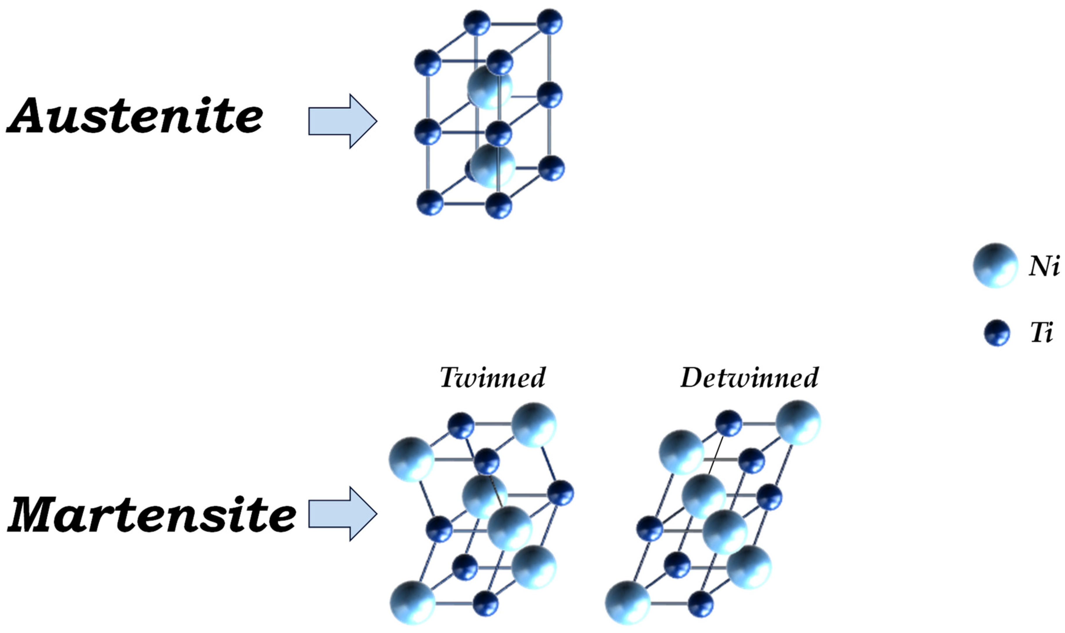
23]. Moreover, the martensite phase may be categorised as an aligned (detwinned martensite phase) or as a non-aligned (twinned martensite phase) crystalline structure, depending on the thermomechanical conditions which induced the martensite phase transition. Therefore, for engineering applications such as actuators, three different crystal structures can be identified corresponding to the various phases shown in
Figure 1 for a Nickel-Titanium alloy as an example. Overall, 24 monocline variants can be derived from the parent cubic phase [
32].
According to
Figure 1, the crystal lattice of the austenite phase is composed of a Nickel atom placed in the centre of the crystallographic cube and titanium atoms at the eight vertexes of the cell. Differently from the austenite phase, no atoms are placed in the centre of the crystal lattice of the martensite phase; instead, atoms are present on all the vertices of its monoclinic B19′ structure. This substantial difference in the crystal lattice between the austenite and martensite phases leads to a difference between their mechanical characteristics and, thus, mechanical performances.
Moreover, according to the specific combination of stress and temperature reported in the phase diagram shown in
Figure 2, it is possible to achieve a defined allotropic form.
The relationship between transformation start stress and temperature shown in
Figure 2 is complex and can depend on the martensitic fraction, as noted in prior studies. However, the simplified representation used here is intended to be representative of the general behaviour of SMA materials. According to
Figure 2, the terms
Ms and
Mf are the characteristic start and finish temperatures of the Martensite, respectively, in free-stress conditions [
33]. Similarly, the terms
As, and
Af denote the start and finish temperatures of austenite, respectively, in free-stress conditions. Moreover, for temperature values lower than
Mf, the SMA material appears in its Martensite allotropic form. When the temperature exceeds the martensite desist temperature (
Md) [
33,
34,
35], the
becomes the yield stress of austenite. Under these conditions, the material behaves in a more stable and predictable state, maintaining the characteristic properties of austenite. In detail, considering the range temperature [
Mf −
Ms], an increase of stress value induces a re-orientation of the crystallographic variants from the twinned (
Mt) to the detwinned (
Md) form. On the contrary, austenite allotropic form occurs when, simultaneously, the combination of low stress and temperatures higher than
Af is satisfied.
Furthermore, a mid-region can be encountered, in which both the austenitic and martensitic phases coexist (A, Mt, Md).
Finally, the graph displays three transition zones as follows:
- a.
The first zone, identified by a maximum temperature value equal to Mf, corresponds to the phase transition from martensite twinned to martensite detwinned.
- b.
The second zone is defined by temperatures between Mf and Mms. In this zone, the phase transition from austenite to martensite twinned (low-stress values) or martensite detwinned (high-stress values) occurs.
- c.
The third zone is defined by temperatures between As and Af. In this zone, the phase transition from martensite detwinned to austenite occurs.
Furthermore, as highlighted in
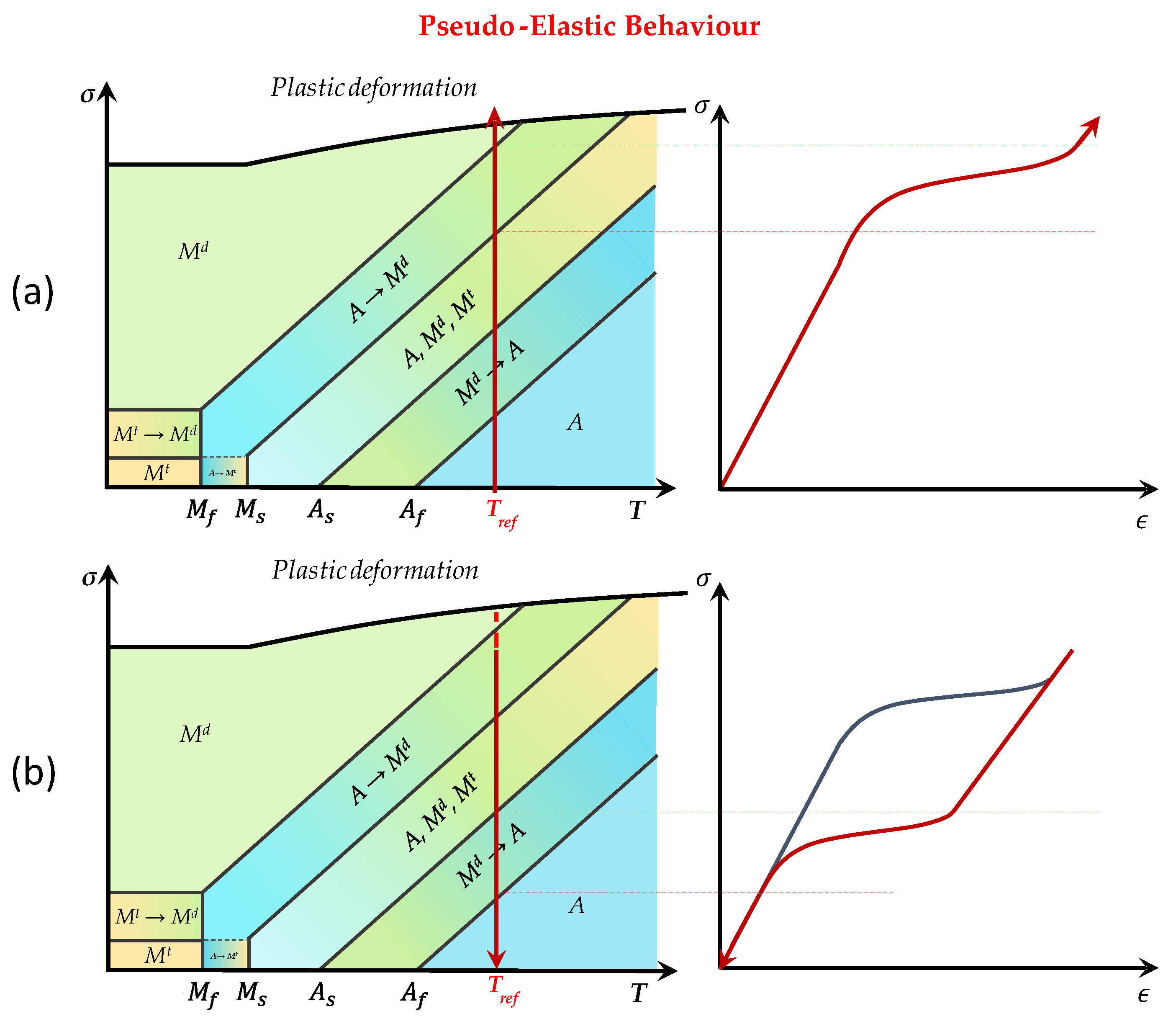
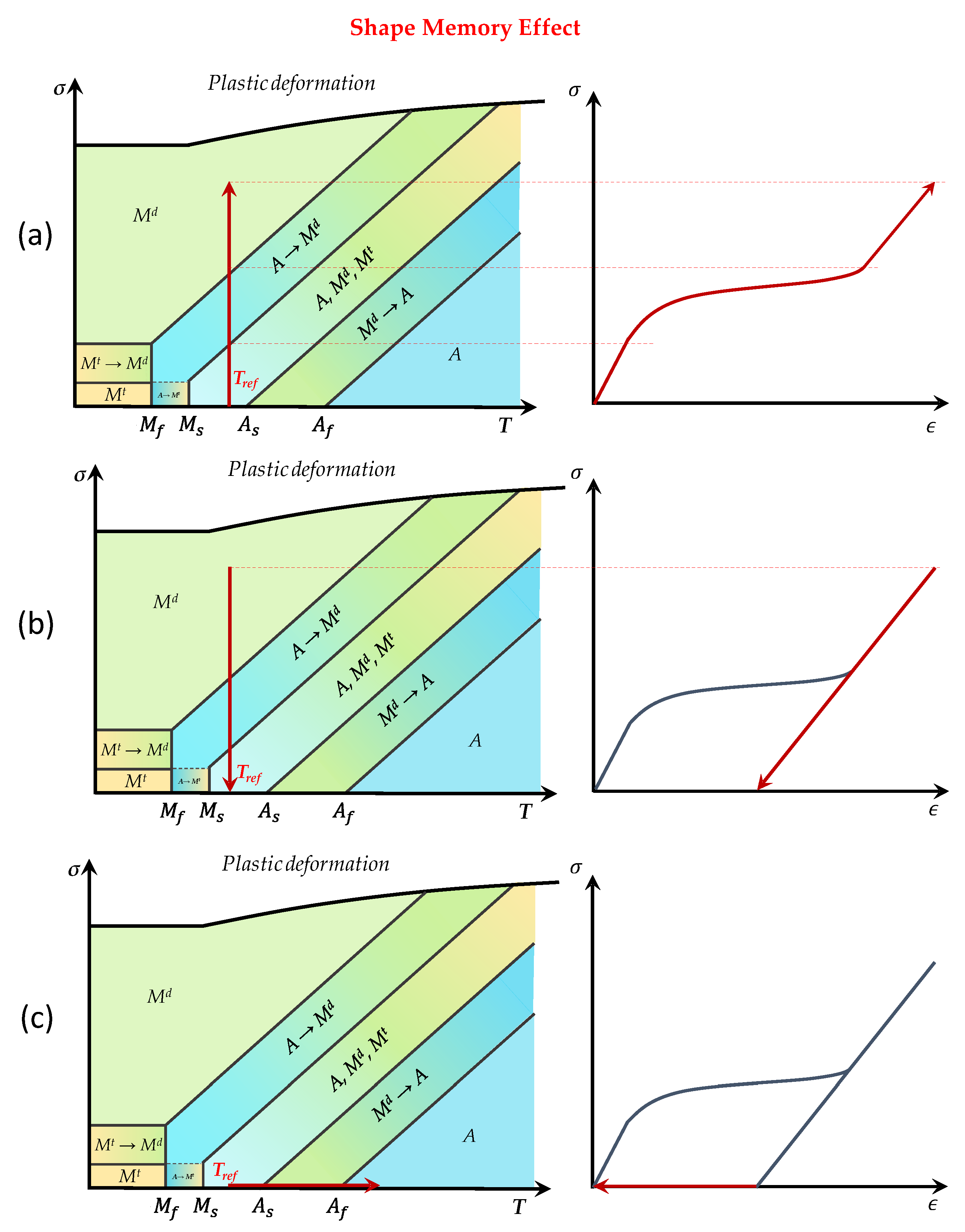
Figure 2, high-stress values induce permanent plastic deformations. The transition between phases results in two SMAs’ interesting capabilities: the pseudo-elastic behaviour and SME. Both characteristics can be noted considering variations of the mechanical and/or thermal applied loads. In
Figure 3 and
Figure 4, the thermomechanical behaviour of the two effects is described in accordance with changes in temperature (T), deformation (
ε) and stress (
σ). In the context of this work, only the SME is required for the actuator design. However, the pseudo-elastic effect is also introduced here for the sake of completeness to provide a full overview of the fundamental properties of SMAs.
According to the phase diagram reported in
Figure 3a, the material is initially considered in free-stress condition at a temperature T
ref greater than austenite transformation temperature (
Af). The condition
Af <
Ms for the maximum stress level prior to plastic deformation has to be also satisfied for this effect. Otherwise, the material will plastically deform before it starts any martensitic transformation. Hence, the SMA is in its Austenitic phase. A stress increase (the temperature is kept constant) triggers the stress-induced martensite (SIM) phenomenon, the phase transition from austenite to martensite is induced by the stress variation. The removal of the stress (the temperature is still kept constant—
Figure 3b) induces a reverse transformation (from martensite to austenite). This reverse transformation does not produce any residual deformations: this effect is known as pseudo-elastic behaviour.
Figure 4 describes the SME. An initial temperature
Tref (in the range
Ms −
As) is considered on a free-stress SMA. Then, the material is stressed (
Figure 4a) until the martensite is detwinned and then released (
Figure 4b) while maintaining a constant temperature
Tref. A residual deformation can be observed, as illustrated in the sigma-epsilon diagram in
Figure 4b. The increase in the temperature allows the recovery of residual deformation at zero stress, inducing the transition from the martensite to the fully austenite phase (
Figure 4c) [
36].
FEM Implementation of Thermomechanical Behaviour of Shape Memory Alloy
The thermomechanical behaviour of SMAs, including their pseudo-elasticity and SMEs, has been implemented within a user material subroutine in the ABAQUS/2020 standard finite element environment [
37]. The routine is composed of a sequence of operations, performed for each time increment and integration point. From a macroscopic point of view, it can be briefly described in three macro sequences as follows:
The system’s compliance matrix is evaluated from the austenite (
A) and martensite (
M) compliance matrices, and mediated by the volumetric fraction of martensite (
ξ) according to Equation (1):
The stress-strain and stress-temperature relationships are evaluated according to the simplified graph reported in
Figure 5.
In
Figure 5, five points in the stress-temperature state diagram and the corresponding points in the stress-strain chart are identified. These points correspond to the forward and reverse start and beginning transformations at a reference temperature
Tref. The characteristic values of the stress, strain and temperature are evaluated according to Equations (2)–(8):
Finally, the routine evaluates the thermal matrix, and the stress and the strain vectors are updated. The overall thermal matrix is evaluated starting from the evaluation of the thermal matrix of the two single phases (austenite and martensite) weighted by the volumetric variation of martensite as expressed by Equation (9):
The tensile and deformation vectors are updated by recalculating the compliance matrix according to Equation (10):
where the variation of the compliance matrix is expressed as a function of the thermal matrix, its variation, the temperature at the previous integration step, the temperature at the current calculation step and the reference temperature according to Equation (11):
While the variation of the thermal matrix (equation) is a function of the volumetric fraction of martensite:
3. SMA Actuator
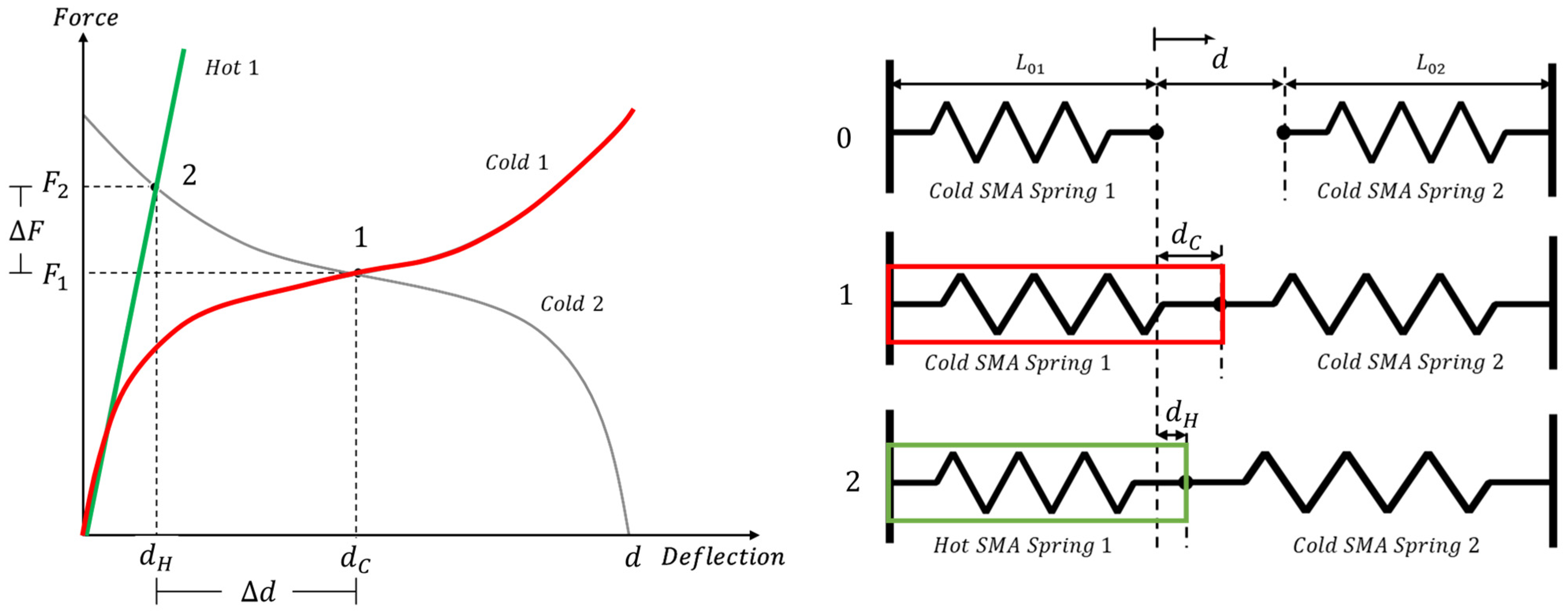
The SME can be exploited by SMA-based actuators to produce forces during their actuation. In particular, the latter can be described as devices composed of at least one primary SMA component (wire or spring) and of an antagonistic component (an external load, a bias spring, or a secondary SMA spring) able to provide a restoring force on the primary SMA component [
38]. In conventional biased actuator designs, an elastic spring is typically used to oppose the SMA, providing the necessary restoring force. However, in the actuator design presented in this study, two SMA springs are used in opposing phases. In this configuration, one of the SMA springs acts as the primary actuator, while the other SMA spring serves as the bias spring during each actuation cycle. In this arrangement, each SMA spring alternately takes the role of the bias element as the system transitions between configurations. The behaviour of SMA-based actuators, with two SMA springs operating in opposing phases, is described in
Figure 6.
According to
Figure 6, the free ends of the primary spring and the antagonistic element (SMA spring) are connected, applying a pre-stretch to both elements. In this configuration, identified as 1 on the left side of
Figure 6, an equilibrium point (point 1) will be reached by both elements. This equilibrium point is characterised by a displacement
dC and load
F1. In this configuration, both SMA components are in the martensitic phase. Then, one of the SMA springs is heated, increasing its temperature above the transition temperature. A phase transition occurs (from martensite to austenite), resulting in a different elastic modulus. A new equilibrium point is then reached (point 2), characterised by a displacement
dH and load
F2. The difference between displacements
dH and
dC, Δ
d, is the stroke of the actuator, while the difference between the forces
F2 and
F1, Δ
F, is the load exerted by the actuator.
3.1. Bistable SMA Actuator with Locking System
Bistable SMA actuators represent a technological innovation that combines the unique properties of SMAs with bistable behaviour, enabling them to exist in two stable configurations. These devices have gained significant attention in recent years due to their ability to provide reliable and efficient actuation in various applications. These actuators can hold a position without requiring continuous power consumption. They use electrical, magnetic or mechanical latching mechanisms to maintain their position, requiring power only during the transition between their two stable states. In this research, the application of shape memory alloys in the context of bistable actuators for controlling automotive spoiler motion has been examined. The designed actuator can be positioned within the side panels and ensure an actuation force sufficient to rotate the spoiler. Regarding the loads, aerodynamic forces are simulated as pressure exerted across the entire surface. The proposed device is composed of different components: a central body, two SMA springs, two block systems and two cranks. In
Figure 7, the assembled device is shown.
In this system, the bistability is accomplished through the combination of SMA and locking system. The SMA spring provides the necessary external energy to overcome the intermediate unstable position. Once this threshold is passed, the potential energy stored in the bias springs drives the mechanism to its second stable position, ensuring it remains locked without the need for continuous energy input. This integrated approach allows the device to function as a true bistable mechanism, with the locking system playing a crucial role in maintaining stability in both positions.
The SMA springs exhibit different mechanical states depending on the temperature. At low temperatures, the springs are in a contracted state due to the martensitic phase. However, upon heating, the springs transition to the austenitic phase, during which they recover their pre-compressed length and become elongated.
All components of the actuator, except for the SMA springs, are constructed from steel, characterised by an elastic modulus of 210 GPa and a Poisson’s ratio of 0.33 [
14].
The bistable actuator is characterised by two opposing-phase SMA springs and a central block that slides along buttonholes (
Figure 7).
The bias springs, two placed in each buttonhole, ensure locking in both configurations. Once the force of the SMA spring exceeds that of the bias springs’ preload, the central block slides along the buttonhole and relocks into the second configuration (
Figure 8). The locking mechanism has been carefully dimensioned and engineered to ensure it can withstand potential aerodynamic overloads. During the design process, analyses of aerodynamic forces were carried out to determine the maximum loads that the spoiler and flaps could be subjected to. The preload of the bias springs was specifically calibrated to ensure that the force required to overcome the locking mechanism significantly exceeds these aerodynamic forces, preventing unintended unlocking. The mechanism’s geometry further contributes to its ability to withstand such forces, ensuring stable operation under all expected conditions.
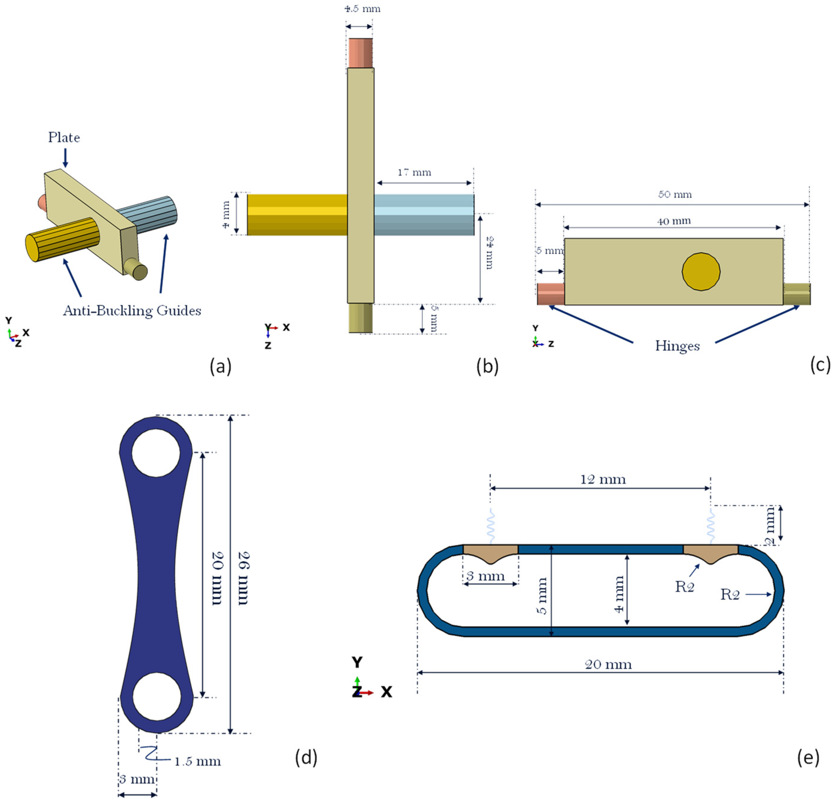
The central body, as illustrated in
Figure 9, has two anti-buckling guides and two hinges linked to the plate’s extremities. The anti-buckling guides facilitate the compression and expansion of the SMA springs along a specified axis. It should be noted that the placement of the anti-buckling guides is intentionally asymmetric. This design choice is necessary to accommodate the installation of the device within the internal mechanisms of the spoiler. However, it does not influence the functionality and does not compromise the actuator’s performance. Simultaneously, the hinges enable relative rotation between the cranks and the central body plate during the actuation process. This occurs while the central body plate is displaced along the
x-axis, as depicted in
Figure 9b, by the action of the SMA springs.
The actuator’s requirement is to ensure the final rotation of the spoiler. To convert the linear motion of the actuator into rotational motion, cranks have been designed. These cranks, when securely fastened to the skin of the spoiler, can achieve the defined rotational movement. The dimensions and shape of the crank are shown in
Figure 9d. The figure illustrates the remarkable efficiency of the design, characterised by its compact dimensions. This efficiency not only saves space but also contributes to enhanced performance, making it a standout feature of the system.
The locking system is composed of a guide in which the central body can slide, two components at the top of the locking system and two conventional springs connected to the devices that can move along the
y-axis of
Figure 9e. In
Figure 9e, the geometric characteristics of the locking systems are reported; the stiffness of metal springs on the left is 80 N/mm while the stiffness of the other two on the right is 30 N/mm. The stiffness of the conventional springs and the shape of the two devices in the locking system are designed to withstand the operating loads acting on the spoiler and the preload of SMA springs in the two configurations. However, when the axial component of the force generated by the traditional springs is lower than the force generated by the SMA spring in the transition phase, the central body starts its movement, compressing the other SMA spring and transitioning to the second stable position.
For the specific design, two SMA springs, sharing identical alloy composition and dimensions, have been employed. Each of these springs consists of seven active turns, and their geometric attributes are detailed in
Figure 10. Mechanical and thermal properties are provided in
Table 1 for reference.
3.2. SMA Spring Analysis
The analysis of SMA springs assumes crucial importance within the design of bistable actuators. The dimensioning of the SMA spring used in this study has been carried out in accordance with the procedure described in [
39]. Once the geometric characteristics have been defined, numerical analysis is conducted to verify the exerted force. To assess the actuator’s force-carrying capabilities, an in-depth numerical examination of the force produced by an individual SMA spring during compression and heating phases is proved. The initial stage of this evaluation involves the compression of the SMA spring, with the purpose of assessing the load exerted by the SMA at the outset of the analysis.
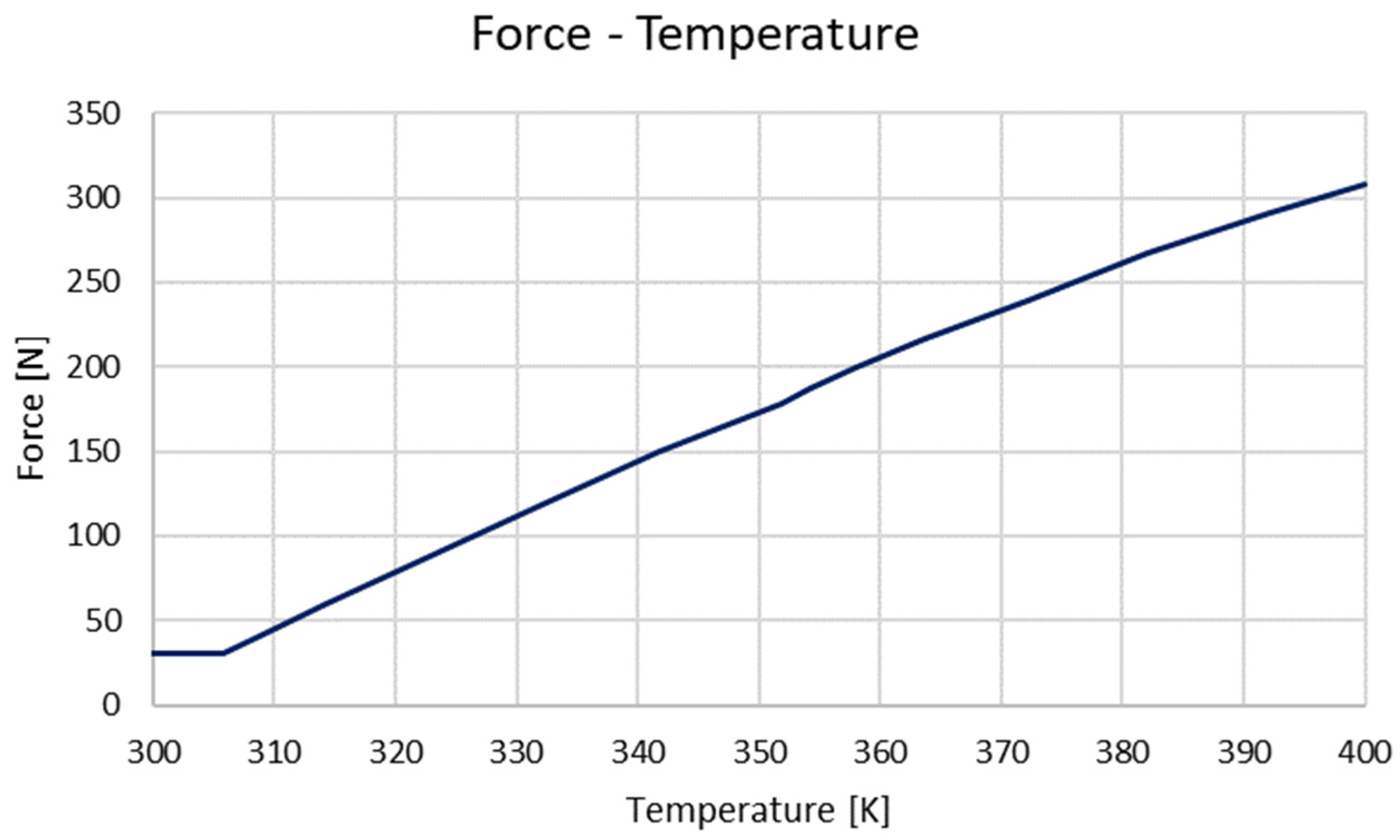
The simulation was carried out with a reference temperature of 300 K. The SME was evaluated by increasing the temperature to 400 K. The spring force was measured at approximately 30 N when compressed by 20 mm, and upon heating to 400 K, the force increased to 310 N, as shown in
Figure 11 and
Figure 12. The heating was modelled using the Joule effect, with the temperature rise representing the applied heating, rather than directly simulating the current input.
The maximum load corresponding to a compressive displacement of about 20 mm will be equilibrated by the secondary SMA spring at the beginning of the analysis. In
Figure 11, the pseudo-elastic response is observed. In particular, the material is initially in the austenitic phase. The increase in the displacement (with the increase in the stress) induces the phase transformation from the austenite phase to the martensite detwinned phase. This phenomenon is highlighted in
Figure 11 by the plateau of the graph. At approximately 90% of the load, the spring was entirely transformed into martensite. During the simulation, one end of the spring was fixed, and the other end was subjected to a controlled displacement. The reaction force was measured in the direction of the applied load and plotted against the imposed displacement.
The SMA SME is evaluated by monitoring the load exerted when a heating load of 400 K is applied starting from a reference temperature of 300 K applied on the SMA springs.
Figure 12 reports the load as a function of the temperature.
Figure 12 highlights that the maximum spring force corresponds to the value of about 310 N and a temperature of about 400 K.
Phase transformations are governed by the change in the volumetric fraction of martensite, which comprehensively encompass the material changes occurring when exposed to mechanical or thermal loads. The implementation employed in this research possesses the capability to analyse the distribution of the volumetric fraction of martensite within the spring at each temporal step. In particular, this implementation takes into consideration non-constant temperature fields, as the heating of the SMA elements occurs in response to the application of electrical current. This process, commonly referred to as the Joule effect, results in the gradual heating of the spring along its section, as opposed to maintaining a constant temperature.
Figure 13 illustrates the volumetric distribution of martensite. At a precise temporal instance within the analysis, it becomes apparent that the distribution of the volumetric fraction varies between outer and inner regions, as well as between areas near the load and those farther away. This disparity reflects the intrinsic nature of SMAs, which, during the application of loads, continuously alter their crystal structure. Consequently, this model can show these differences, track their changes and conduct an instant and in-depth evaluation of the suitability of the chosen spring configuration. However, it should be noted that in the context of this preliminary analysis, both the asymmetric stress-strain behaviour between tension and compression and the hysteresis effects, which are known characteristics of SMAs, have not been explicitly accounted for. While these factors can significantly influence the performance of SMAs, particularly in reversible mechanisms, they were not considered critical to the focus of this study, which is on the general thermomechanical behaviour of the material and the feasibility of the actuator design.
4. Application on an Automotive Spoiler
This section presents a comparative static analysis of two separate configurations exposed to an aerodynamic load, simulated at a pressure of 0.00021 N/mm
2 on the top side of the surface. The value represents a symbolic pressure indicating a constant applied velocity across the entire profile, as no aerodynamic load has been considered for this preliminary analysis. Specifically, the first application involves the assessment of the entire spoiler under a pressure load (
Figure 14a,c). The second case regards the movement of only the flap (
Figure 14b,d).
The spoiler features a NACA 4412 airfoil profile and spans a length of 1400 mm with a chord length of 130 mm. In the pursuit of weight reduction and enhancing the structural performance of the component, a composite material with a quasi-isotropic stacking sequence [0, 90, 45, −45] has been employed. Mechanical properties are detailed in
Table 2.
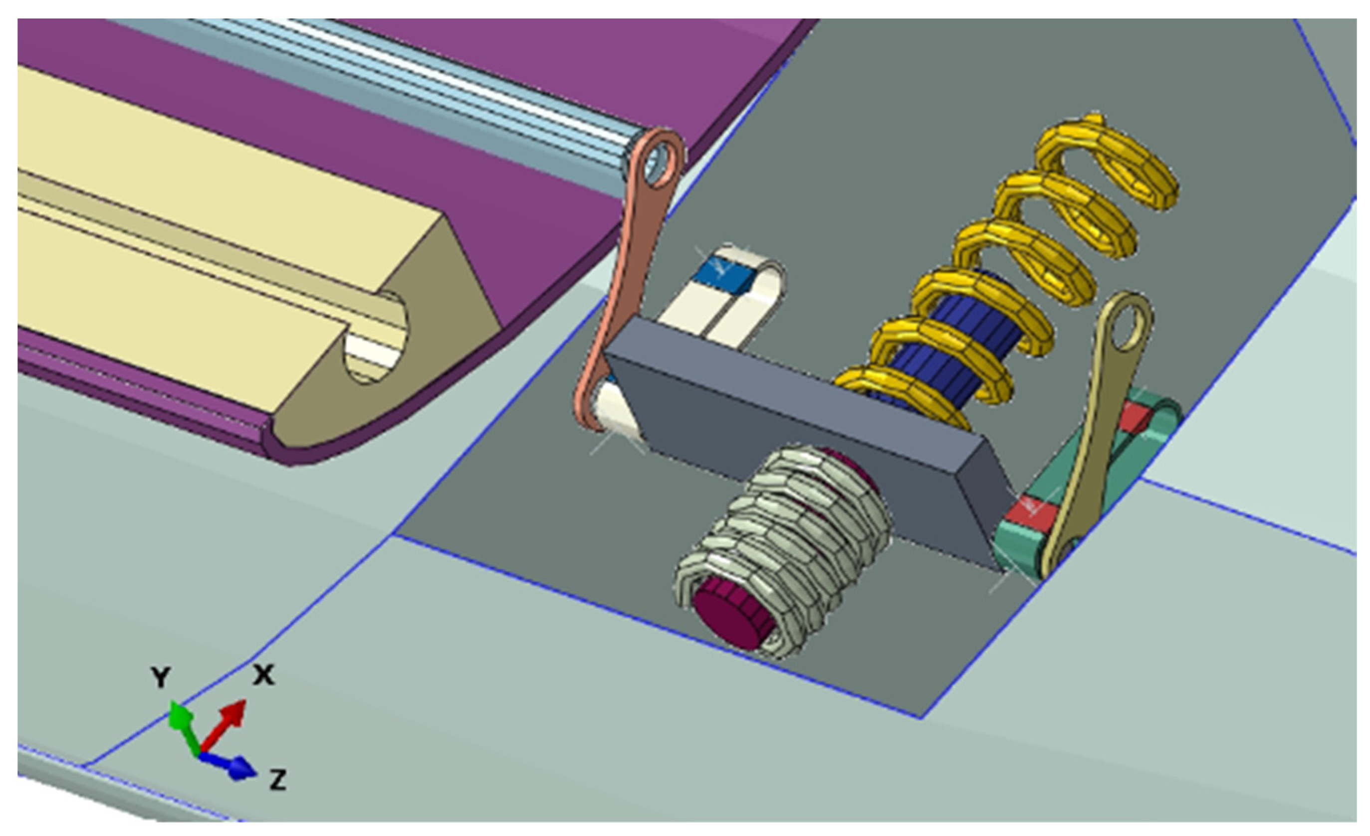
Figure 15 illustrates the integration of the actuator, which is completely recessed within the side panels, with both the spoiler and the flap. The fully concealed connection represents a deliberate design choice that presents numerous advantages. Primarily, it imparts a cleaner and aesthetically pleasing aspect by concealing mechanical or connecting components within the structure, thereby creating a sleek and uniformly surfaced exterior.
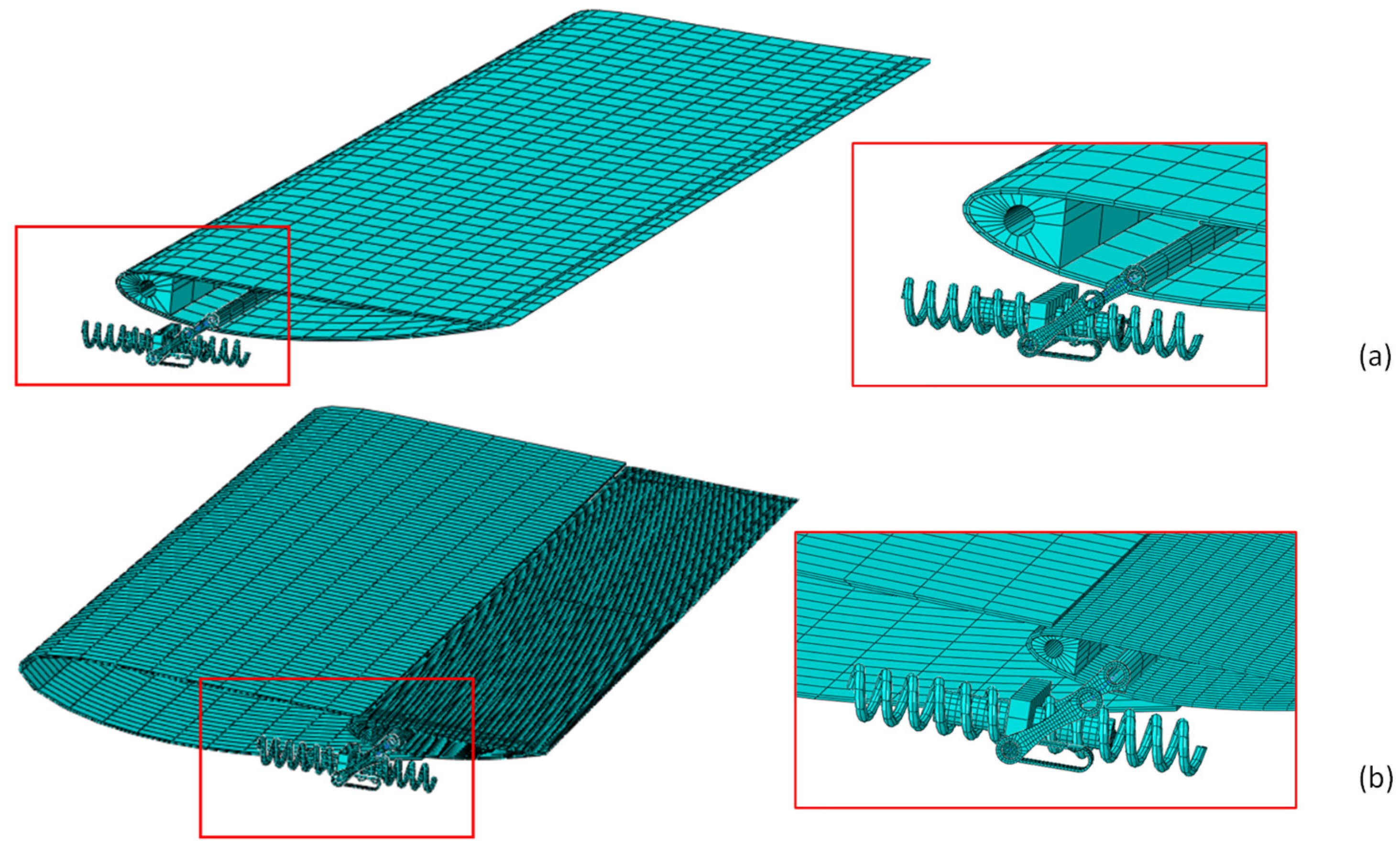
The Finite Element (FE) model has been discretized using 8-node brick elements employing a full integration scheme (C3D8) for both the actuation system and the spoiler (
Figure 16).
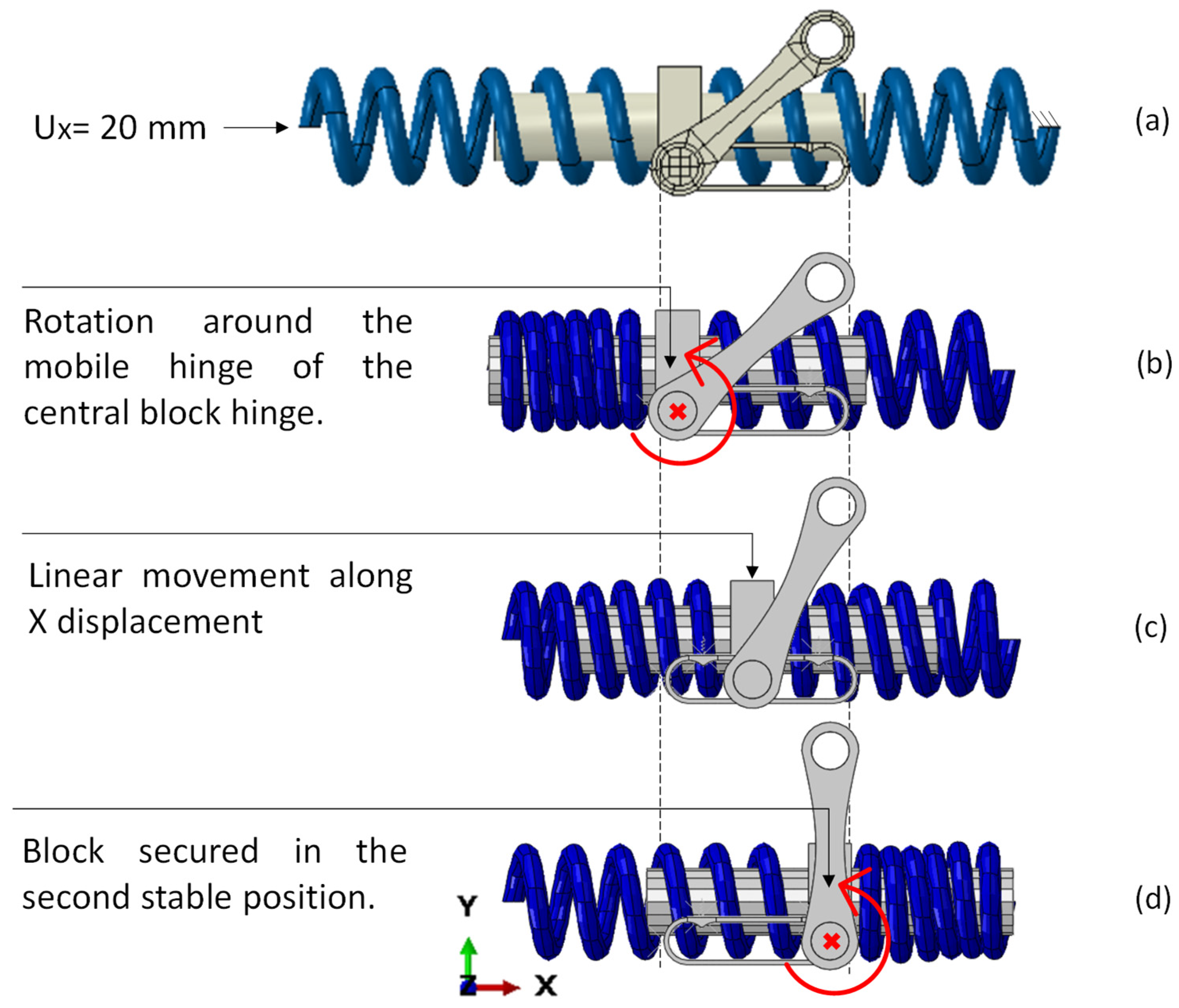
The schematic diagram in
Figure 17 provides a systematic overview of the actuator’s functionality. After precompression of the SMA springs (
Figure 17a), the buttonholes remain fixed in position, while the central block undergoes linear motion along the buttonhole guides (
Figure 17c). During this movement, it overcomes both sets of biasing springs, ultimately securing itself in the second equilibrium position (
Figure 17d).
Simultaneously, the crank, which is linked to the mobile component, starts a rotational motion (
Figure 17b) as the spoiler moves linearly. This rotational action occurs around the hinge, affecting both the spoiler and the flap. This designed system transforms linear displacement into precise and controlled rotational motion, offering a versatile solution for actuation.
This incorporation of both linear and rotational motions demonstrates the efficiency and complexity of the actuation process, enabling dynamic adjustments to the aerodynamic features of the automotive system.
First of all, conducting an analysis to calculate the actuation force is essential as it represents a fundamental parameter for the proper functioning of systems involving an actuator. This analysis enables the determination of the actuation force required for the desired motion or action within a system. This information is critical during the design and sizing phase of the actuator itself, as it helps define the specifications and necessary features to meet the system’s requirements.
Moreover, the analysis of actuation force is essential for sizing SMA springs. Specifically, depending on the force value, it is advisable to optimise the diameter, coils, and length of the springs to achieve a fully optimised SMA spring. These parameters influence the structural behaviour and phase transformations of the spring. Depending on the equilibrium of forces, it becomes feasible to select geometric configurations for the springs that guarantee full martensite transformation subsequent to the compression step.
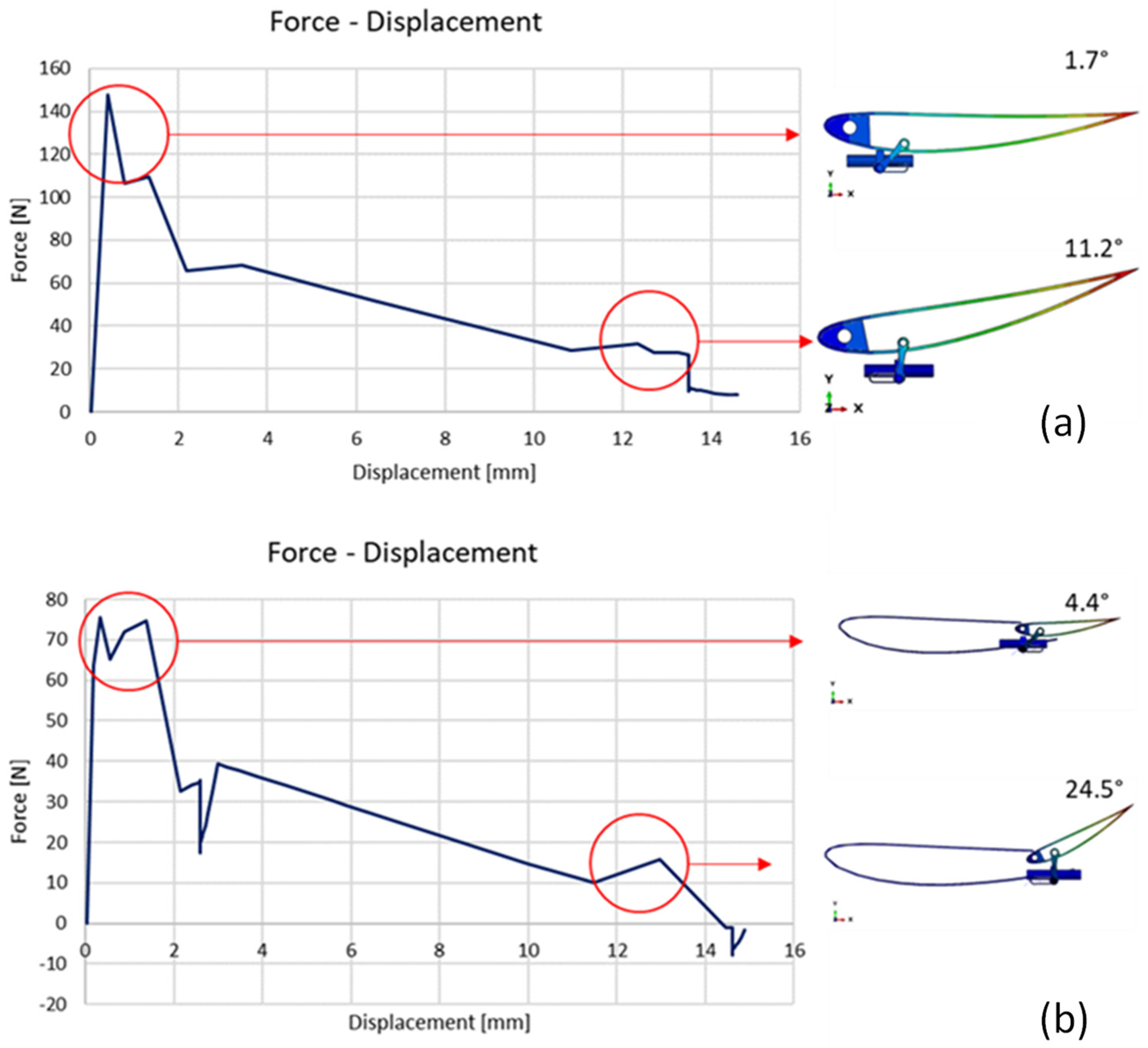
To assess the actuation force of both systems, a displacement of the central block along the X-direction of 15 mm was applied. The linear motion of the actuator enables the crank to rotate the spoiler.
As evident from
Figure 18, the configuration enabling the rotation of the entire spoiler requires a higher force compared to the motion of just the flap. In general, rotating only the flap can modify the angle of attack or the exposed area to airflow without affecting the entire system, enabling more precise control, and minimising aerodynamic disturbances. Furthermore, the second solution requires less energy than rotating the entire system, as there is less mass to move and less aerodynamic resistance to overcome. This can lead to significant energy savings, particularly in applications where energy efficiency is crucial. Additionally, it is worth noting that the rotation of the flap alone (
Figure 18a) is twice that of the spoiler (
Figure 18a).
The first configuration is appropriate when the objective is to minimise aerodynamic resistance or maintain a stable aerodynamic profile during typical speed-driving or for the purpose of fuel efficiency. Conversely, the second configuration proves advantageous when the task is to enhance traction at high speeds or augment stability during cornering manoeuvres.
Therefore, the maximum force value between the two configurations is approximately 150 N. The SMA spring has been dimensioned such that with a temperature input of 400 K, it achieves a force of 310 N, which is twice the required force.
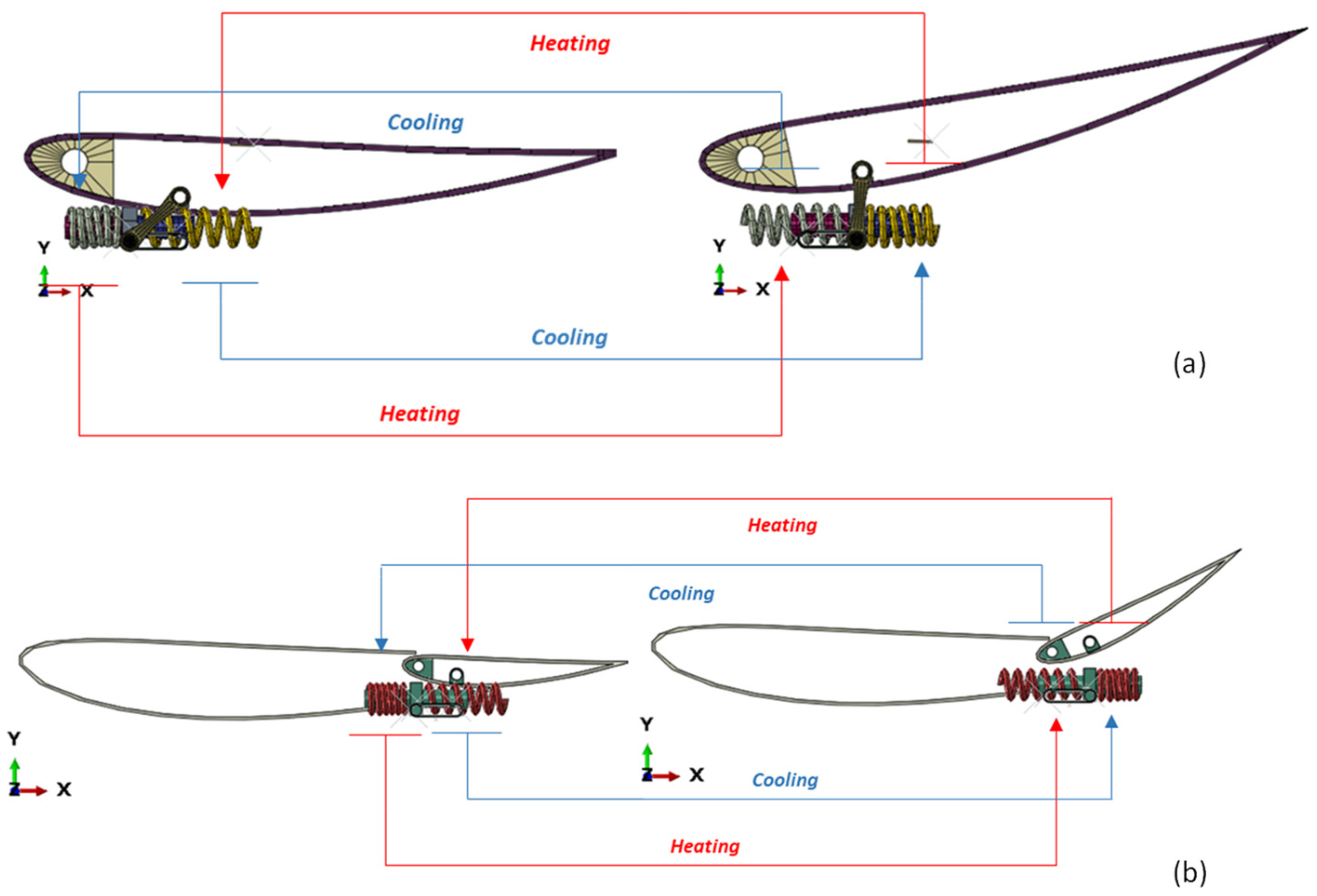
Figure 19 provides an overview of the system’s final configuration, featuring both the actuator and the SMA springs. Two different configurations primarily differ in the actuator’s positioning within the side panels. In the case of the configuration involving the movable flap, the actuator is retracted from its initial position by approximately 50 mm.
Subsequently, the spring on the left side of the actuator is compressed by 20 mm. Upon reaching this compressed state, the spring is subjected to heating to a temperature of 400 K. This thermal input enables it to effectively overcome the combined forces exerted by the opposing-phase springs, the load and the inherent spring resistance. Following this phase, the spring is rapidly cooled, and the process is repeated with the spring on the right side, again at the same temperature of 400 K. This sequence of compression, heating and cooling serves as the underlying mechanism driving the actuation process, allowing for precise control of the spoiler’s movement.
Finally, the key contribution of this study lies in the design of a bistable actuator that achieves significant force while occupying a remarkably small space. The numerical results validate the actuator’s performance and demonstrate its effectiveness in meeting the desired force requirements despite its compact size. This result highlights the impact of the research, particularly in applications where space constraints are critical, such as in automotive industries. By addressing the challenge of combining high force output with minimal footprint, these numerical findings allow for advanced actuator solutions that can be integrated into various state-of-the-art technologies.
