Article

Study of Self-Excited Thermomechanical Oscillator with Shape Memory Alloys

1
Department of Theory of Mechanisms and Machines, Faculty of Industrial Technology, Technical University of Sofia, 1797 Sofia, Bulgaria
2
Department of Manufacturing Technology and Systems, Technical University of Sofia, 1797 Sofia, Bulgaria
*
Author to whom correspondence should be addressed.
Actuators 2024, 13(5), 182; https://doi.org/10.3390/act13050182
Submission received: 8 April 2024 / Revised: 7 May 2024 / Accepted: 9 May 2024 / Published: 11 May 2024
(This article belongs to the Special Issue Shape Memory Alloy (SMA) Actuators and Their Applications)

Abstract

:
In this paper, a new type of self-excited thermomechanical oscillator containing an oscillating shape memory alloy (SMA) filament with two symmetrically arranged spheres is investigated. The self-excitation of the oscillations is due to a heater of constant temperature, which causes periodic contractions of the filament when it approaches it. The contracted filament moves away from the heater a distance sufficient to cool it. Under the action of the weight of the spheres, the cooled filament re-approaches the heater, causing the above processes to repeat periodically. On the basis of experimental studies, approximating functions of the heater’s heat field distribution are derived. A dynamic model of the oscillator has been created, in which the minor and major hysteresis in the SMA alloy and the distribution of the heat field around the heater have been taken into account. Through numerical solutions of the differential equations, the laws of motion of the spheres are obtained. The displacements of the spheres in two perpendicular directions were measured using an experimental system. The obtained experimental results validate the proposed dynamic model and its assumptions with a high degree of confidence. Conclusions are drawn about the stochastic nature of the oscillations due to the hysteresis properties of the SMA and the temperature variation of the natural frequency of the oscillating system.

1. Introduction

Self-excited oscillations accompany many technological processes and, in most cases, have detrimental effects on them. The main reasons for their occurrence are mainly the dependence of friction forces on relative sliding, changes of normal loads, viscoelastic interactions, or the influence of various geometrical effects [1,2,3].
It has been shown that purely temperature-focussed self-excited oscillations cannot exist because the heat conduction equation, unlike other equations of mechanics, is not invariant under time reversal. Periodic thermally forced self-excited oscillations that propagate as waves are possible [4]. The combination of thermal and mechanical vibrations is known by the term thermomechanical oscillations (TMO). The foundations of the theory of TMOs were laid in 1829 by A. Travelian [5] and were later further developed by M. Faraday, A. Tyndal, and J. Rayleigh. Some of the first theoretical and experimental studies of the conditions for the occurrence of self-excited thermomechanical oscillations were reported by Nesis E. I. [4]. Awrejcewicz and Pyryev [6] created a massless elastic element model of frictional self-excited vibrations and investigated the possibilities of their existence.
Thermomechanical self-excited oscillations have a negative influence on many technological processes. To show that the loss of stability in constant speed cutting is due to thermomechanical self-excited oscillations, authors Astashev and Korendyasev [7] investigated the model of heat generation in the cutting region. Fel’dshtein [8] investigated self-excited thermomechanical oscillations of current-carrying wires by determining the existence conditions and describing them by numerical simulations. Toda et al. [9], using the Barenblatt model, investigated the thermomechanical self-excited oscillations that occur during cold drawing of films. A technique to stabilize and suppress the oscillations in an optothermomechanical oscillator is demonstrated in [10].
In microelectromechanical systems (MEMS), thermal processes occur at a much higher rate than in conventional macrosystems due to the significantly lower values of temperature and time constants. And in these systems, one can note detrimental effects of self-excited thermomechanical oscillations, such as those induced by laser heating of double-clamped MEMS beams [11], or the induced frequency self-locking that occurs when laser illuminating thin MEMS resonators [12,13].
The micrometric dimensions of thermally exposed components in MEMS create conditions for building fundamentally new devices in which self-excited thermomechanical oscillations are the basis of their operating principle. One such large class of MEMS are self-excited thermomechanical microresonators [14,15], which are in competition with their capacitive [16] and piezoelectric analogues [17].
Shape memory alloys (SMAs) are smart materials possessing the property of remembering a shape, which, if changed within certain limits, can be fully recovered by heating. When the change of the shape is brought about by stretching due to tensile stress, the SMA specimen tends to shorten to its original undeformed dimensions when it is restored. This behavior is used to create relatively low-cost actuators that possess several advantages, such as generating large forces and displacements at high energy density and noiselessness. Thermal activation of SMAs creates conditions for cyclic control [18,19,20] and, in many cases for self-excitation, of thermomechanical oscillations [21,22,23,24]. In their low-temperature state, SMAs have a martensitic crystallographic structure which is soft and deformable. Martensite has two crystallographic forms: a twinned and a detwinned form. Undeformed martensite is called twinned, and it preserves the set shape. When deformed, martensite changes to its detwinned crystallographic form, achieving a large strain in the order of 8%. Once heated, the SMA transforms into the austenitic state where the memorized shape is recovered. The crystallographic transformation temperatures depend on their chemical composition and can be tailored over a wide range.
Oscillating systems based on shape memory alloys are widely used in energy harvesting technologies. Several researchers use SMA substrates on which they deposit a piezoelectric layer to generate electricity by vibration [25,26,27,28]. Another interesting application of SMAs in energy harvesting systems is the two-step conversion of heat to mechanical and then mechanical to electrical energy [29,30,31]. A peculiarity of thermomechanical models with SMAs are the nonlinearities arising from the hysteresis in the stress–strain, stress–temperature, and temperature–strain relationships. The existence conditions of oscillatory modes of nonlinear thermomechanical self-excited systems with hysteresis are a challenge for modern research in the field of differential equations and control theory [22,32].
The most popular methods for self-excitation of SMAs are via the Joule effect, i.e., heating with an eclectic current [33]; via convection using heaters [29]; and radiatively, for example, via solar energy [34].
The aim of this paper is to create a mathematical model of a new self-excited thermomechanical oscillator with SMA filament, to validate the obtained results experimentally, and to draw conclusions about the type and parameters of oscillations. In the development of the mathematical model, the aim is to describe the thermodynamic processes in detail, considering the hysteresis phenomena in the SMA filament.

2. Design Concept of the Self-Excited Thermomechanical Oscillator

The schematic of the self-excited thermomechanical oscillator is shown in Figure 1. The structure is symmetrical consisting of an SMA filament OABC, rigidly fixed at both ends, on which two metal spheres in points A and B are arranged. Nitinol (NiTi) SMA was used for the filament [33]. A heater is fixedly located at the base of the thermomechanical oscillator. At room temperature (T0 = 20 °C), the SMA filament is in a martensitic state.
The principle of the oscillator is as follows: Under the action of the weight of the two spheres, the SMA filament sags and approaches the heater at position OA1B1C. The proximity of the filament to the heater raises its temperature and causes contraction while, at the same time, hardening it. The contracted filament rises back vertically under the temperature, moving away from the heater at position OA0B0C. This is followed by a lowering of the temperature and a softening and relaxation of the filament. As a result, under the weight of the spheres, the filament falls again and approaches the heater at position OA1B1C. This is followed by a cyclic repetition of the above processes, resulting in periodic oscillations of the system.

3. Building a Dynamic Model and Determining the Input Data for Its Solution

The SMA filament in the static position is pre-stretched between the OC supports. The distance between the supports is assumed to be OC = 2l, and the half-length of filament before tensioning is ls. Thus, for half of the prestrain of the SMA filament, Δ l s 0 is valid:
Δ l s 0 = l l s .
The x-axis of the coordinate system Oxy is chosen to lie on the segment OC, and its origin is located in the middle of the same segment. Symmetrically to the y-axis on the OC segment, two points, A 0 and B 0 , are selected, at which two spheres of equal mass (m) are fixed. The distances along the horizontal x-axis are denoted by c l 10 = O A 0 , l 20 = A 0 B 0 , and l 30 = B 0 C . Since for the relative lengths, the notations
l 01 l = l 03 l = λ 0 ,
are chosen; then, for the deformations from the prestressing, Δ l s 10 and Δ l s 30 in the end sections O A 0 and B 0 C will follow:
Δ l s 01 = Δ l s 03 = Δ l s 0 λ 0 ,
and in the middle section ( A 0 B 0 ), this deformation will be
Δ l s 012 = 2 Δ l s 0 1 λ 0 .
It can be seen in Figure 1 that due to the symmetrical arrangement of the heater and the SMA filament, only the middle section of the AB will be heated. It is assumed that the temperature of this section is distributed uniformly along its length.
Since the dynamic model will be constructed using the Lagrange equations of the second kind, the kinetic energy of the oscillator is represented in the following form:
E k = m 2 x ˙ A 2 + x ˙ B 2 + y ˙ A 2 + y ˙ B 2 ,
where x ˙ A   , x ˙ B   are the velocities of points A and B on the x-axis, and y ˙ A   , y ˙ B   are the velocities of points A and B on the y-axis.
The end sections OA and BC are assumed not to heat up, unlike the middle AB section, which changes its temperature and Young’s modulus, so the potential energy takes the following expression:
E p = k l 2 Δ l 1 2 + Δ l 3 2 + k T 2 Δ l 2 2 ,
where k l is the elastic constant of the extreme cold sections, k T is the elastic constant of the middle warm section,
Δ l 1 = x A   x O 2 + y A   y O 2 l 10 + Δ l s 0 λ 0
Δ l 3 = x B   x C 2 + y B   y C 2 l 30 + Δ l s 0 λ 0
are the deformations of the end sections, and x O , x A , x B , x c   y O , y A , y B , and y c are the coordinates of points O, A, B, and C.
For the middle section, the deformation depends on the mutual position of points A, B, and the pre-deflection of the filament:
Δ l 2 = x A   x B 2 + y A   y B 2 l 20 + 2 Δ l s 0 1 λ 0 .
The stiffness of the end sections is
k l = E 1 A l 01 ,
where A is the cross-sectional area, and the Young’s modulus E 1 is
E 1 = E m ,
where E m is the NiTi module in the martensitic state. This is the case if it is assumed that the temperature in the final sections is lower than the final martensitic temperature, i.e., T < Mf. The Young’s modulus according to [31] is equal to the modulus of NiTI in the fully martensite state.
For the middle section, the stiffness is
k T = E 02 A l 20 ,
where the Young’s modulus E 02 is defined by the piecewise function
E 2 = E a E a E m R m i f 0 ε s 2 ε m y E a E a E T R m i f ε m y ε s 2 ε m d E a E a E d R m i f ε m d ε s 2 ,
where E m , E T , E d , and E a are Young’s modulus of the fully twined, partially twined, detwinned martensite, and austenite, respectively; ε m y is the yield strain of the twined martensite; ε m d is the minimum strain of the detwinned martensite; and
ε s 2 = Δ l 2 l 02 = x A   x B 2 + y A   y B 2 l 20 + 2 Δ l s 0 1 λ 0 l 20
is the current strain of the middle section of the filament.
The relative martensitic fraction R m of NiTi is calculated according to [31], and to investigate the major and minor hysteresis, similarly to [18], it is modified in the following form:
R m = S R 2 1 + tanh T m T λ T + R C S R ,
where S R is a scale factor dependent on the temperature fluctuation, R C is a factor dependent on where the temperature change point is located, and λ T is a relative temperature dependent on the crystallographic transformation temperatures of the NiTi. The temperature T m depends on whether the thermal process is heating or cooling and is obtained by the following relation:
T m = 1 2 A S + A f i f d T d t > 0 M s + M f i f d T d t < 0 .
The coefficient λ T has unit °C and, here, it has the following form:
λ T = 1 2 A S + A f b a c a i f d T d t > 0 M s + M f b m c m i f d T d t < 0 ,
and As, Af, Ms, and Mf are the start and final temperatures for austenite and martensite of SMA. The limiting values of the coefficients, b a < 0.5 ( A f A s ) , b m < 0.5 ( M s M f ) , c a < 0.5 , and c m < 0.5 have been established experimentally [31].
The major and minor hystereses of the relative martensitic fraction are determined using the method described in [18], adapted for the model of [31]. In summary, this method is based on the points at which the temperature process changes from warming to cooling and vice versa. According to the adopted method, if the temperature gradient change point T f is in the transition periods when both martensite and austenite fractions are present in the SMA, i.e.,
T f M s , M f A f , A s ,
the scale factor of the martensitic fraction acquires the values of the case of transition from heating to cooling, equivalent to
T ˙ f > 0 a n d T ˙ f < 0 ,
where T ˙ f and T ˙ f are the temporal temperature gradients before and after the onset of the fluctuation, respectively. The scale factor of the martensitic fraction has the following form:
S R = 1 i f M S > T f > M f R m f = 1 2 1 + tanh T m T f λ T i f A f > T f > A S ,
and the fraction
R C = 0 i f M S > T f > M f 0 i f A f > T f > A S .
If, at the change point, the temperature changes from cooling to warming, then the following applies:
T ˙ f < 0 a n d T ˙ f > 0 .
The scale coefficients are, respectively,
S R = 1 R m f M S > T f > M f R m f = 1 2 1 + tanh T m T f λ T i f M s T f M f ,
and
R C = 0 i f M f > T f > A f 1 R m f i f M s > T f > M f .
A sub minor hysteresis occurs if a minor hysteresis already exists after the point T f . The temperature at which sub minor hysteresis occurs is denoted by T f s . The other important conditions for sub minor hysteresis existing are when cooling, M f < T f s < M S , and when warming, A S < T f s < A f .
For a sub minor hysteresis, the following scale factors are valid for the warming-to-cooling transition:
S R = 1 i f M f > T f S > A f R m f s = 1 2 1 + tanh T m T f S λ T i f A f > T f S > A S ,
and
R C = 0 i f M S > T f S > M f 0 i f A f > T f S > A S .
At the transition from cooling to warming, the scale coefficients are
S R = R m f R m f s i f M f > T f S > A f R m f s = 1 2 1 + tanh T m T f S λ T i f M s > T f S > M f ,
and
R C = 0 i f M f > T f S > M s 1 R m f c i f M s > T f S > M f .
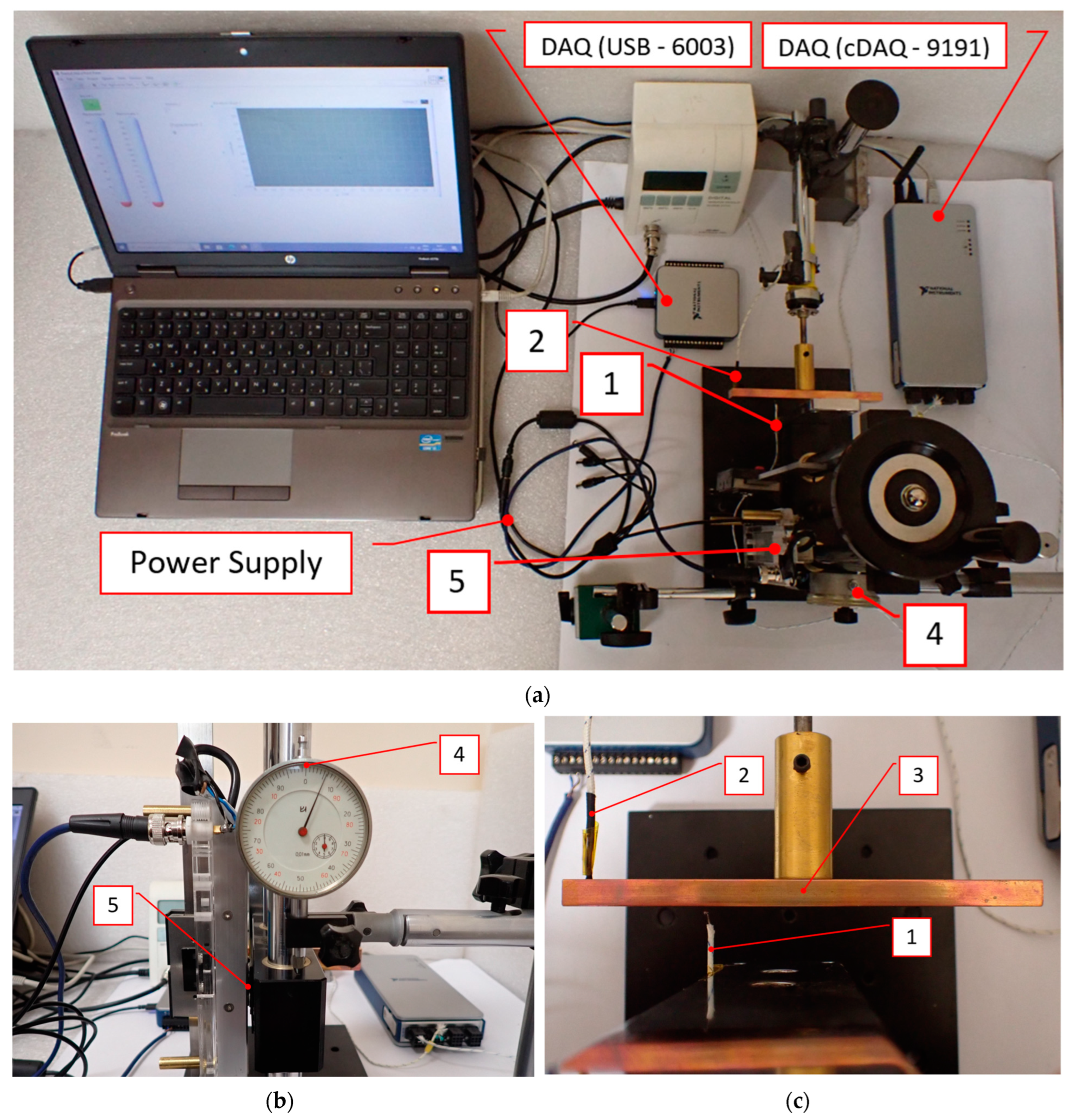
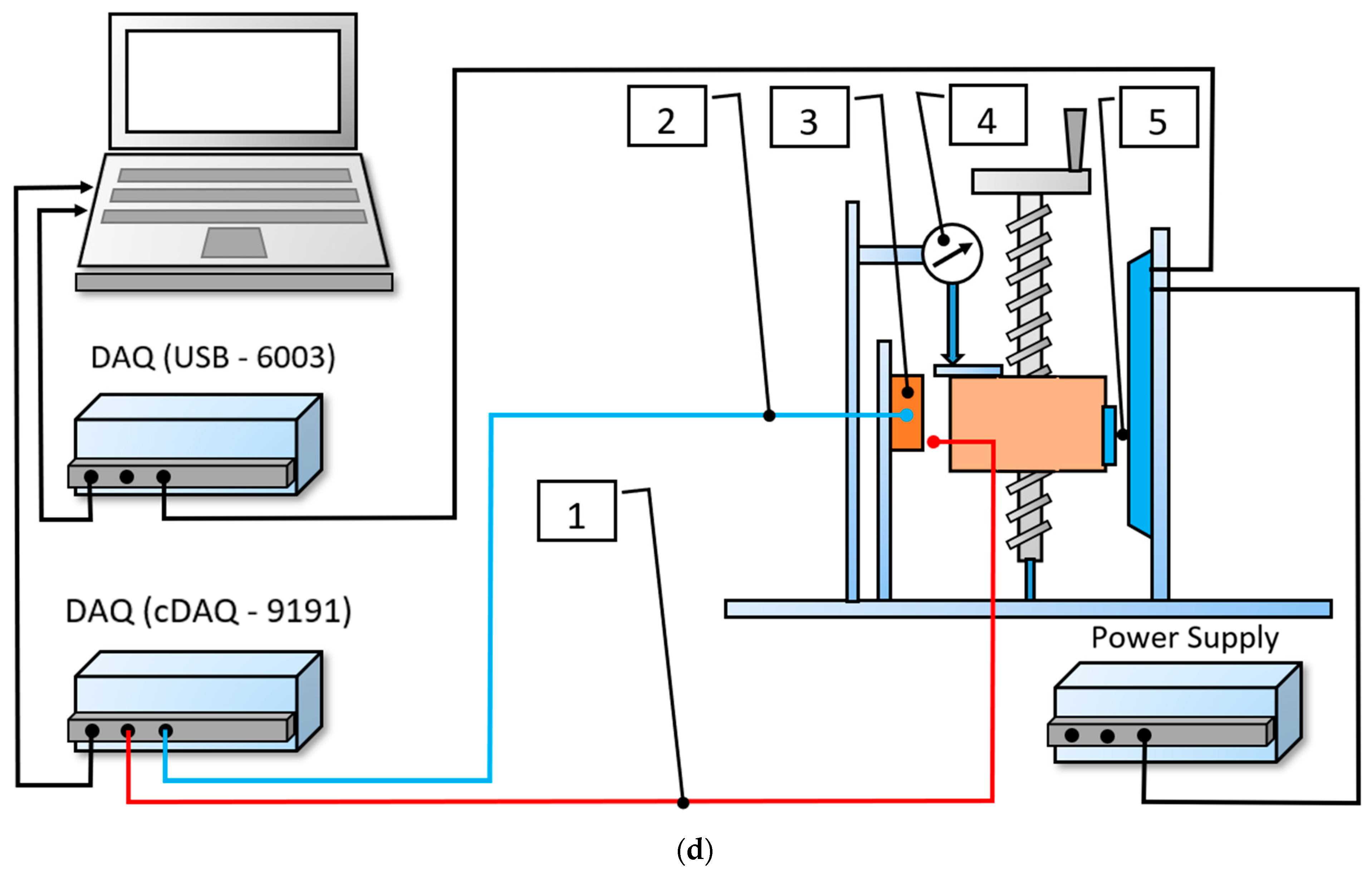
To determine the heater temperature distribution in the area where the SMA filament moves, the experimental setup shown in Figure 2 was designed. The temperature in the vicinity of the heater (3) was measured using a movable thermocouple (1), the position of which was set using an inductive position sensor (5) type APO-075-002-000 of TT Electronics Ltd., Woking, UK. The constant temperature of the heater is measured by a thermocouple (2) which is fixed in its body. A mechanical dial gauge (4) was also added to the experimental system to calibrate the data of the inductive sensor (5). The data from the two thermocouples are fed to a data acquisition system (DAQ) type cDAQ -9191, and the inductive sensor signal is fed into a DAQ type USB -9191 of National Instruments Ltd. The data are processed and recorded by a LabVIEW program. Different values of the constant temperature of the heater are set using a thermostat, and by changing the position of the movable thermocouple, the type of heat field in the vicinity of the heater is determined.
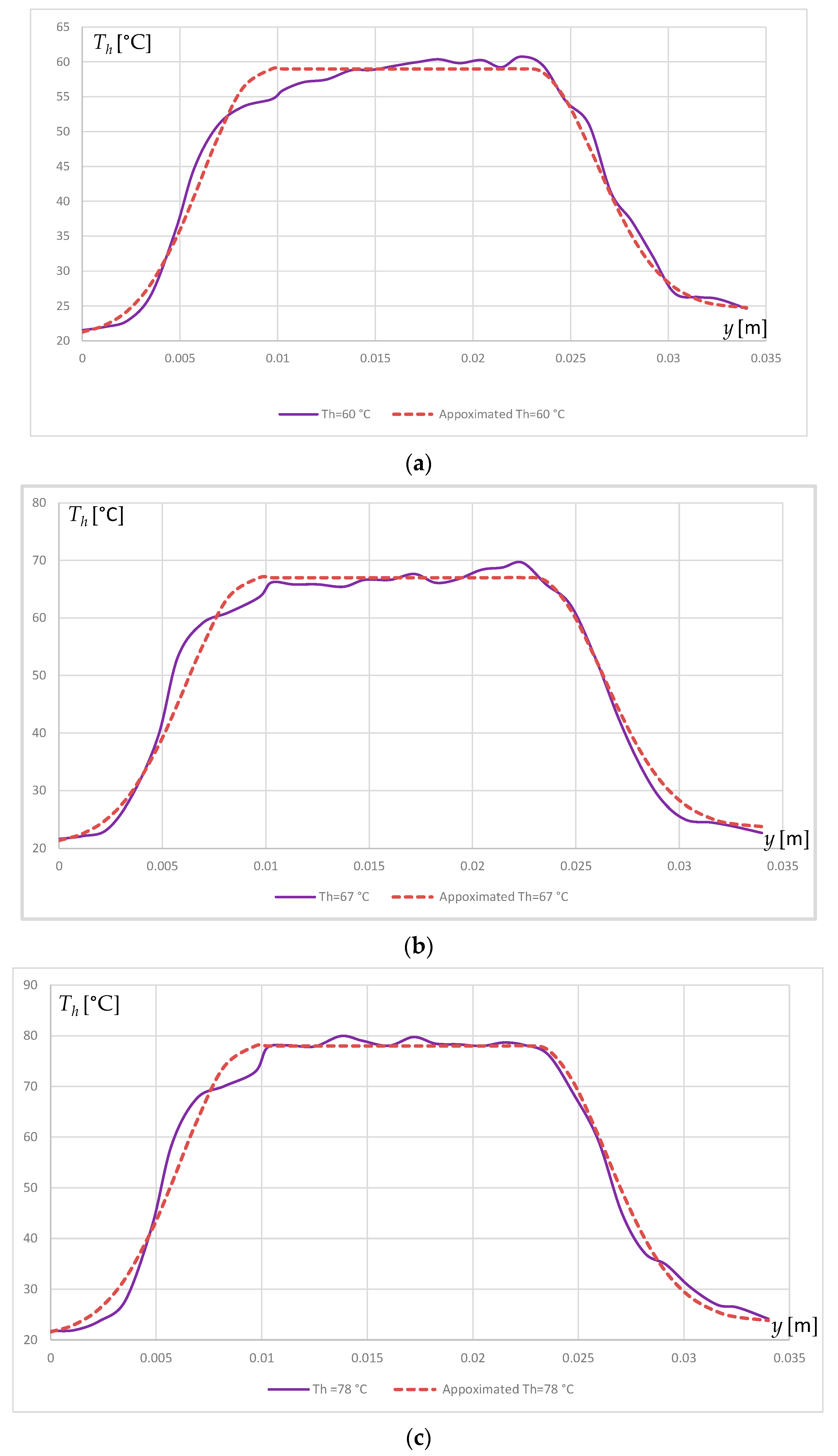
Based on the experiments, the temperature of the filament in the middle part is assumed to be a stationary function of the y coordinate defined by the piecewise function:
T = T h T 0 e y y e θ 2 + T 0 i f y < y e T h i f y e y y f T h T 0 e y y f θ 2 + T 0 i f y > y f ,
where y e , y f are coordinates dependent on the heater position determined experimentally (Figure 3), T h is the maximum temperature received by the filament from the heater, θ is a conditional length defining the slope of the curve T = T(y), and T 0 is the room temperature.
In Figure 3 the experimental values of the hater’s thermal field for three maximal temperatures—60, 67, and 78 °C—are presented with solid lines. The corresponding approximated thermal fields are presented with dashed lines.
The approximated heat field function along the vertical coordinate gives rise in this model to consideration of the relative martensitic fraction as a complex function of the y A coordinate and time t, i.e.,
R m = R m y A t .
From this, it follows that the Young’s modulus and stiffness of the SMA filament in the middle section are considered, respectively, to be
E 2 = E 2 x A t , y A t ,
and
k T = k T x A t , y A t .
The assumption about the temperature dependence of the middle section on the y position leads to the representation of the thermal stiffness as a function of time. The potential character for the temperature distribution near the heater provides a rationale for deriving the filament forces from the SMA to be derived via the second-order Lagrange equations.
It is assumed that the motion of the filament is such that the oscillator is only in its symmetric configuration, where x B   = x A , y B   = y A , x O   = l , x C   = l , y C   = y O = 0, l 30 = l 10 , Δ l 3 = Δ l 1 , and l = O C / 2 .
In this case, the Lagrangian of the oscillator takes the following form:
L = E K E P = m x ˙ A 2 + y ˙ A 2 k l Δ l 1 2 2 k T x A , y A Δ l 22 2 y A ,
where the symmetry-transformed deformation of the middle section is rewritten as
Δ l 2 = 2 Δ l 22 x A .
Here, Δ l 22 x A expresses the following:
Δ l 22 x A = x A l 20 2 + Δ l s 0 1 λ 0 ,
Which can be rewritten as
Δ l 22 x A = x A + l 22 , l 22 = l 20 2 + Δ l s 0 1 λ 0 .
The strain of the middle segment is expressed as
ε s 2 = 2 ( x A + l 22 ) l 20 ,
and the deformation of the end section is converted into the following:
Δ l 1 = x A   + l 2 + y A 2 l 10 + Δ l s 0 λ 0 .
In the above formula, the expression l 10 + Δ l s 0 λ 0 is denoted as l 11 , and the deformation of second section obtains the following form:
Δ l 1 = x A   + l 2 + y A 2 + l 11 .
The differentiation of the Lagrangian is performed with respect to the generalized coordinates x A   and y A   and the generalized velocities x ˙ A   and y ˙ A   , according to the Lagrange equations of the second kind:
d d t L q ˙ i L q i = Q i i = 1 , 2 ,
where { q 1 , q 2 } = { x A , y A } , { q ˙ 1 , q ˙ 2 } = { x ˙ A , y ˙ A } и, and { Q 1 , Q 1 } = { β x x ˙ , 2 m g β y y ˙ } are the generalized coordinate, generalized velocity, and generalized force, respectively, and are the damping coefficients along the x and y axes.
After differentiation according to (40) the system of differential equations is derived:
m x ¨ + k l Δ l 1 x d Δ l 1 x , y d x + k T x , y x Δ l 22 x 2 + 2 k T x , y Δ l 22 x d Δ l 22 x d x = β x x ˙ m y ¨ + k T x , y y Δ l 22   x 2 k l Δ l 1 x d Δ l 1 x , y d y + k T x , y y Δ l 22 x 2 = m g β x y ˙ ,
where the derivative of the filament end segment with respect to x is
d Δ l 1 x d x = x + l x + l 2 + y 2 .
The derivative of the middle filament segment with respect to x is
d Δ l 22 x d x = 1 .
The stiffness k T does not depend on x, and its derivative with respect to x is equal to zero, or
k T x , y x = 0 .
The derivative of k T with respect to y is equal to
k T x , y y = y E 02 A l 02 = A l 02 E 02 y .
In (41), the partial derivative of Young’s modulus with respect to y for the middle section has the following form:
E 2 y = E m E a d R m d y i f 0 ε s 2 ε m y E T E a d R m d y i f ε m y ε s 2 ε m d E d E a d R m d y i f ε m d ε s 2 .
The relative martensite fraction, taking into account the heater heat field distribution function (29), is modified into
R m = S R 2 1 tanh T m T h e 1 θ 2 y y e + T 0 λ T + R C S R i f y y e S R 2 1 tanh T m T h + T 0 λ T + R C S R i f y e < y < y f S R 2 1 tanh T m T h e 1 θ 2 y y f + T 0 λ T + R C S R i f y y f .
The derivative of the relative martensite fraction in this case is
d R m d y = S R T h 2 λ T θ 2 e 1 θ 2 y y e 1 tanh T m T h e 1 θ 2 y y e + T 0 λ T i f y y e 0 i f y e < y < y f S R T h 2 λ T θ 2 e 1 θ 2 y y f 1 tanh T m T h e 1 θ 2 y y f + T 0 λ T i f y > y f .
After the simplifications described above, the dynamic model (41) is recast into a system of differential equations:
m x ¨ + E m A x + l x + l 2 + y l 11 l 10 x + l 2 + y + 2 k T x , y x + l 22 = β x x ˙ m y ¨ + k T x , y y x + l 22 2 + E m A x + l 2 + y l 11 y l 10 x + l 2 + y = m g β y y ˙ .
In order to find a numerical solution of the system (49), its order is lowered by the following substitutions:
v ˙ x = E m A x + l x + l 2 + y l 11 m l 01 x + l 2 + y 2 m k T x , y x + l 22 β x 2 m x ˙ x ˙ = v x v ˙ y = E m A x l 2 + y l 11 y m l 10 x l 2 + y k T x , y m y x + l 22 2 g β y 2 m y ˙ y ˙ = v y .
The numerical solution of the system was carried out using the parameters given in Table 1.
To solve the system (50), a numerical solution program was created using an implicit fifth-order Euler method. The solutions of the system of differential Equation (50) were obtained under zero initial conditions for the velocities x ˙ and y ˙ , and the initial conditions for the coordinates of the masses were taken as x 0 = 0.1 and y 0 = 0.01 .

4. Conducting the Experiments and Comparing the Results

The displacements of the spheres along the x and y coordinates were measured synchronously in real time using the experimental system shown in Figure 4. A photograph of the system is shown in Figure 4a, and its simplified block diagram is depicted in Figure 4b. Filament 1 is immovably clamped on two supports (6). Two spheres (4) are arranged symmetrically with respect to the heater (3) and the fixed supports. On the filament adjacent to the spheres, movable sensing elements of non-contact inductive sensors (2) and (5) are mounted, which are type APO-075-002-000 of TT Electronics Ltd., UK. In order to detect the simultaneous displacement of the spheres in the horizontal x-direction and the vertical y-direction, the movable sensing elements and the sensor bodies are oriented at 90 degrees to each other. In Figure 4, sensor (2) measures the x-axis sphere displacement, and sensor (5) is oriented to measure the vertical y-displacement of the sphere. The signals from the two sensors are input to the data acquisition system DAQ USB-6003 from National Instruments then processed by a laptop using a LabVIEW program. The data from both sensors and the heater temperature are recorded in an Excel file.
Multiple experiments were conducted by varying the weights masses, the initial tension of the SMA filament, and the heater temperature, which was kept constant using a thermoregulator.
In the experiments, it was found that for oscillations to occur, certain conditions concerning the pre-tension of the SMA filament and the difference in room and heater temperature needed to be met. The most significant influence for the occurrence of oscillations is the initial position of the filament relative to the heater. Once the conditions for the oscillations to occur are satisfied, stable oscillations of the filament with both masses are generally observed with unchanging energy (Supplementary Materials).
Analysis of the experimental results shows that the self-excited oscillations have a stochastic character. The reason for the appearance of the random processes is due to the nonlinear hysteresis variations of the Young’s modulus of the SMA, which are a function of the temperature, the sign of its gradient, the type of deformation, and the position of the SMA filament.
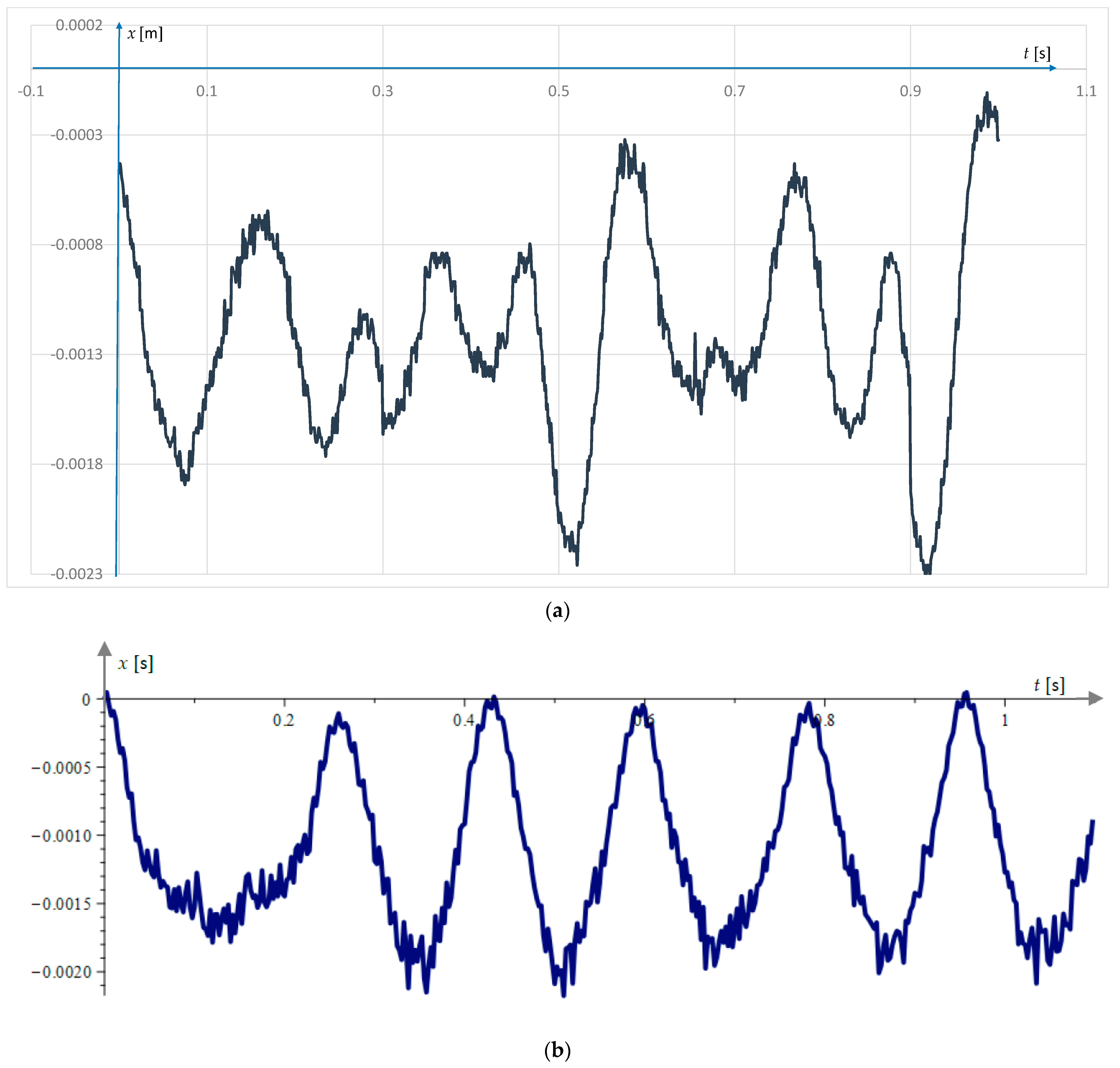
Figure 5a shows the plot of the experimental measurements of the x-axis position of the sphere. It can be seen that the oscillatory motion has a period which varies randomly within certain limits, while the amplitude also varies according to a random distribution law.
An interesting impression of the x-axis oscillations is an extra modulated oscillation with approximately 20 times the frequency and approximately 5 times the amplitude. This modulation is also confirmed in Figure 5b, which represents the result of the theoretical model for the x-axis oscillations. The logical explanation for this phenomenon, according to the authors, is the existence of a purely mechanical normal vibration of the SMA filament that occurs under the action of the variable axial force. This variable axial force is generated by the thermal contractions of the SMA filament. The difference in the frequencies of the two oscillations is due to the fact that the mechanical oscillations have a frequency which depends on the stiffness of the filament and mass, while the thermal oscillations depend on the vertical position of the filament and primarily on the temperature and time constant of the filament determining the heating cooling time. For the same reasons, the amplitudes of the longitudinal mechanical oscillations have a small value, while the thermal amplitudes can reach up to 8% of the filament length. Thus, the x-axis displacement can be assumed to be the sum of mechanical and thermal random oscillatory motions.
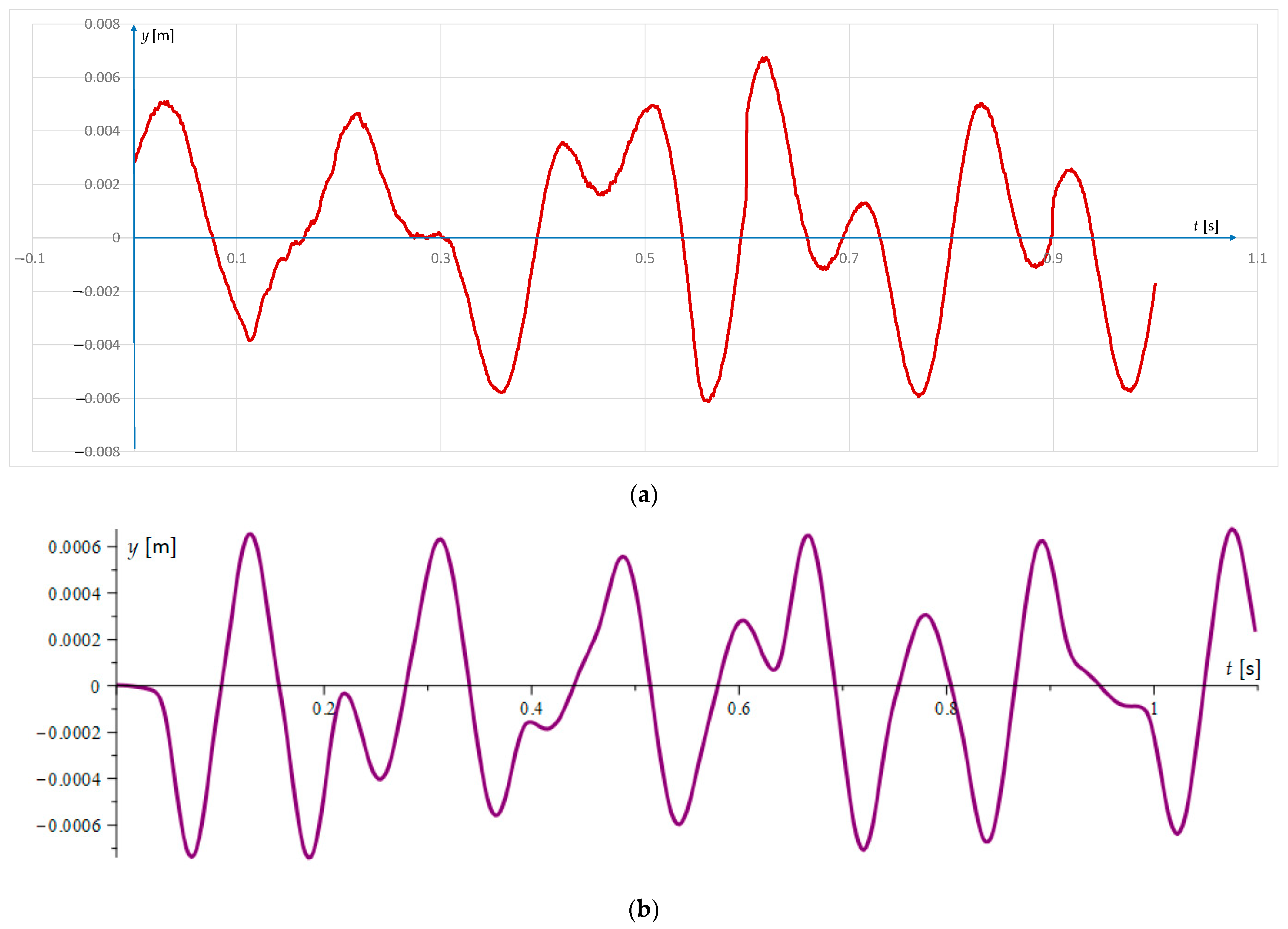
Figure 6 plots the displacements of the sphere along the y-axis. The experimental data are shown in Figure 6a, and the data obtained from the dynamic model are plotted in Figure 6b. It can be observed that stochasticity is also present in the vertical oscillations both in terms of period and frequency. Modulated oscillations along the y-axis direction are not seen in either the experimental data or the data obtained from the theoretical model. The reason for this is that here, the transverse oscillations are purely mechanical, induced by thermal contractions along the x-axis. The appearance of the stochasticity here is also explained by the change in Young’s modulus at different temperatures and strains.

5. Conclusions

A new system for self-excited thermomechanical oscillations based on shape memory alloys was created. The properties of this system are investigated theoretically by a dynamic model in which the hysteresis properties of the SMA are accounted for. The results obtained from the model are confirmed by direct measurements of displacements along two perpendicular directions. Using this experimental method, displacements were obtained with relatively high accuracy since integration errors typical of inertial measurement systems such as MEMS accelerometers or gyroscopes were eliminated. The obtained results show that the oscillations of the system have a stochastic character in terms of frequency and vibration. It is found that due to the birefringent nature of the oscillations along the x-axis, there are two types of oscillations. The main ones, called thermal, have an amplitude dependent on the thermal contractions of the filament and a frequency determined by the temperature time constant of the filament from the SMA. The second oscillations, called purely mechanical, have a frequency dependent on the ratio of the mass of the sphere and the stiffness of the system and an amplitude that is a function of the longitudinal thermal contractions, the natural frequency, and the damping of the SMA filament.

Supplementary Materials

The following supporting information can be downloaded at: https://www.mdpi.com/article/10.3390/act13050182/s1, Video S1: Oscillations of the sensing element of the inductive sensor.

Author Contributions

Conceptualization, T.T. and G.T.; methodology, T.T.; software, T.T.; validation, I.Y.; formal analysis, G.T.; investigation, T.T.; resources, T.T. and I.Y.; writing—original draft preparation, T.T.; writing—review and editing, G.T. and I.Y.; supervision, G.T.; project administration, G.T.; funding acquisition, G.T. All authors have read and agreed to the published version of the manuscript.

Funding

This research was funded by the European Union—NextGenerationEU through the National Recovery and Resilience Plan of the Republic of Bulgaria, project № BG-RRP-2.004-0005.

Data Availability Statement

Data are contained within the article.

Conflicts of Interest

The authors declare no conflicts of interest.

References

  1. Kroger, M.; Neubaer, M.; Popp, K. Experimental investigation on the avoidance of self-excited vibrations. Philos. Trans. R. Soc. A 2008, 366, 785–810. [Google Scholar] [CrossRef] [PubMed]
  2. Ding, W. Modeling and Control. In Self-Excited Vibration; Springer: Berlin/Heidelberg, Germany, 2010. [Google Scholar] [CrossRef]
  3. Papangelo, A.; Putignano, C.; Hoffmann, N. Self-excited vibrations due to viscoelastic interactions. Mech. Syst. Signal Process. 2020, 144, 106894. [Google Scholar] [CrossRef]
  4. Nesis, E.I.; Nesis, S.E. Thermomechanical and thermoacoustic self-excited oscillations. J. Eng. Phys. 1988, 55, 1178–1194. [Google Scholar] [CrossRef]
  5. Khvol’son, O.D. Physics Course; Nabu Press: Berlin, Germany, 1923; Volume 3. [Google Scholar]
  6. Awrejcewicz, J.; Pyryev, Y. Thermo-mechanical model of frictional self-excited vibrations. Int. J. Mech. Sci. 2005, 47, 1393–1408. [Google Scholar] [CrossRef]
  7. Astashev, V.K.; Korendyasev, G.K. Thermomechanical model of the occurrence of oscillations in metal cutting. J. Mach. Manuf. Reliab. 2012, 41, 189–193. [Google Scholar] [CrossRef]
  8. Fel’dshtein, V.A. Thermomechanical Self-Excited Oscillations of Current-Carrying Conductors. J. Appl. Mech. Tech. Phys. 2017, 58, 1091–1098. [Google Scholar] [CrossRef]
  9. Toda, A.; Tomita, C.; Hikosaka, M.; Hibno, Y.; Miyayji, H.; Nonomura, C.; Suzuki, T.; Ishihara, H. Thermo-mechanical coupling and self-excited oscillation in the neck propagation of PET films. Polymer 2002, 43, 947–951. [Google Scholar] [CrossRef]
  10. Weng, W.; Anstie, J.D.; Abbott, P.; Fan, B.; Stace, T.M.; Luiten, A.N. Stabilization of a dynamically unstable opto-thermo-mechanical oscillator. Phys. Rev. A 2015, 91, 063801. [Google Scholar] [CrossRef]
  11. Blocher, D.; Rand, R.H.; Zehnder, A.T. Analysis of laser power threshold for self oscillation in thermo-optically excited doubly supported MEMS beams. Int. J. Non Linear Mech. 2013, 57, 10–15. [Google Scholar] [CrossRef]
  12. Pandey, M.; Aubin, K.; Zalalutdinov, M.R.; Reichenbach, B.A.; Zehnder, T.; Richard, R.H.; Craighead, H.G. Analysis of Frequency Locking in Optically Driven MEMS Resonators. J. Microelectromech. Syst. 2006, 15, 1546–1554. [Google Scholar] [CrossRef]
  13. Pandey, M.; Rand, R.H.; Zehnder, A.T. Frequency Locking in a Forced Mathieu-van der Pol-Duffing System. Nonlinear Dyn. 2008, 54, 3–12. [Google Scholar] [CrossRef]
  14. Wei, L.; Kuai, X.; Bao, Y.; Wei, J.; Yang, L.; Song, P.; Zhang, M.; Yang, F.; Wang, X. The Recent Progress of MEMS/NEMS Resonators. Micromachines 2021, 12, 724. [Google Scholar] [CrossRef] [PubMed]
  15. Miller, J.M.L.; Shin, D.D.; Kwon, H.-K.; Shaw, W.S.; Kenny, T.W. Spectral narrowing of parametrically pumped thermomechanical noise. Appl. Phys. Lett. 2020, 117, 033504. [Google Scholar] [CrossRef]
  16. Chen, C.-Y.; Li, M.-H.; Li, S.-S. CMOS-MEMS Resonators and Oscillators: A Review. Sens. Mater. 2018, 30, 733–756. [Google Scholar] [CrossRef]
  17. Pillai, G.; Li, S.-S. Piezoelectric MEMS Resonators: A Review. IEEE Sens. J. 2021, 21, 12589–12605. [Google Scholar] [CrossRef]
  18. Mitrev, R.; Todorov, T.; Fursov, A.; Ganev, B. Theoretical and Experimental Study of a Thermo-Mechanical Model of a Shape Memory Alloy Actuator Considering Minor Hystereses. Crystals 2021, 11, cryst11091120. [Google Scholar] [CrossRef]
  19. Elahinia, M.H. Shape Memory Alloy Actuators: Design, Fabrication, and Experimental Evaluation; John Wiley & Sons, Ltd.: Toledo, Spain, 2016; p. 621. [Google Scholar] [CrossRef]
  20. Sohn, J.W.; Ruth, S.J.; Yuk, D.-G.; Choi, S.-B. Application of Shape Memory Alloy Actuators to Vibration and Motion Control of Structural Systems: A Review. Appl. Sci. 2023, 13, 995. [Google Scholar] [CrossRef]
  21. Todorov, T.; Mitrev, R.; Yatchev, I.; Fursov, A.; Ilin, A.; Fomichev, V. A Parametric Study of an Electrothermal Oscillator Based on Shape Memory Alloys. In Proceedings of the 21st International Symposium on Electrical Apparatus and Technologies (SIELA), Bourgas, Bulgaria, 3–6 June 2020; pp. 1–4. [Google Scholar] [CrossRef]
  22. Wang, L.; Melnik, R. Nonlinear dynamics of shape memory alloy oscillators in tuning structural vibration frequencies. Mechatronics 2012, 22, 1085–1096. [Google Scholar] [CrossRef]
  23. Mitrev, R.; Atamas, E.; Goncharov, O.; Todorov, T.; Iatcheva, I. Modeling and study of a novel electrothermal oscillator based on shape memory alloys. In Proceedings of the 9th International Scientific Conference “Techsys 2020”—Engineering, Technologies and Systems, Plovdiv, Bulgaria, 14–16 May 2020; Volume 878, p. 012059. [Google Scholar] [CrossRef]
  24. Rusinek, R.; Rekas, J. Modelling of shape memory alloy oscillator and its application to middle ear structural reconstruction. In Proceedings of the 22nd International Conference on Computer Methods in Mechanics, AIP Conference Proceedings, Lublin, Poland, 13–16 September 2018; Volume 1922, p. 100017. [Google Scholar] [CrossRef]
  25. Kumari, N.; Rakotondrabe, M. Design and Development of a Lead-Free-Piezoelectric Energy Harvester for Wideband, Low Frequency, and Low Amplitude Vibrations. Micromachines 2021, 12, 1537. [Google Scholar] [CrossRef]
  26. Yang, F.; Shi, Y.; Liu, J.; Wang, Z.; Tian, X. Design and Experimental Study of Shape Memory Alloy and Piezoelectric Composite Power Generation Device. Micromachines 2023, 14, 1434. [Google Scholar] [CrossRef]
  27. Wang, X.; Qin, Q.; Lu, Y.; Mi, Y.; Meng, J.; Zhao, Z.; Wu, H.; Cao, X.; Wang, N. Smart Triboelectric Nanogenerators Based on Stimulus-Response Materials: From Intelligent Applications to Self-Powered Systems. Nanomaterials 2023, 13, 1316. [Google Scholar] [CrossRef] [PubMed]
  28. Namli, O.; Taya, M. Design of piezo-SMA composite for thermal energy harvester under fluctuating temperature. J. Appl. Mech. 2011, 78, 031001. [Google Scholar] [CrossRef]
  29. Todorov, T.S.; Fursov, A.S.; Mitrev, R.P.; Fomichev, V.V.; Valtchev, S.S.; Il’in, A.V. Energy Harvesting with Thermally Induced Vibrations in Shape Memory Alloys by a Constant Temperature Heater. IEEE/ASME Trans. Mechatron. 2022, 27, 475–484. [Google Scholar] [CrossRef]
  30. Reddy, A.R.; Umapathy, M.; Ezhilaras, D.I.; Uma, G. Piezoelectric energy harvester with shape memory alloy actuator using solar energy. IEEE Trans. Sustain. Energy 2015, 6, 409–1415. [Google Scholar] [CrossRef]
  31. Mitrev, R.; Todorov, T.; Fursov, A.; Fomichev, V.; Il‘in, A. A Case Study of Combined Application of Smart Materials in a Thermal Energy Harvester with Vibrating Action. J. Appl. Comput. Mech. 2021, 7, 372–381. [Google Scholar] [CrossRef]
  32. Fursov, A.S.; Todorov, T.S.; Krylov, P.A.; Mitrev, R.P. On the Existence of Oscillatory Modes in a Nonlinear System with Hystereses. Differ. Equ. 2020, 56, 1081–1099. [Google Scholar] [CrossRef]
  33. Chattaraj, N. Experimental Investigation and Empirical Analysis of a Shape-Memory-Alloy-Actuated Electromechanical Oscillator. J. Vib. Eng. Technol. 2022, 10, 741–750. [Google Scholar] [CrossRef]
  34. Boschetto, A.; Bottini, L.; Costanza, G.; Tata, M.E. Shape Memory Activated Self-Deployable Solar Sails: Small-Scale Prototypes Manufacturing and Planarity Analysis by 3D Laser Scanner. Actuators 2019, 8, 38. [Google Scholar] [CrossRef]
  35. Mitrev, R.; Todorov, T. A Case Study of Experimental Evaluation of the Parameters of Sape Memory Alloy Wires. In Proceedings of the TechSys 2021—Engineering, Technologies and Systems, AIP Conference Proceedings, Plovdiv, Bulgaria, 27–29 May 2021; Volume 2449. [Google Scholar] [CrossRef]
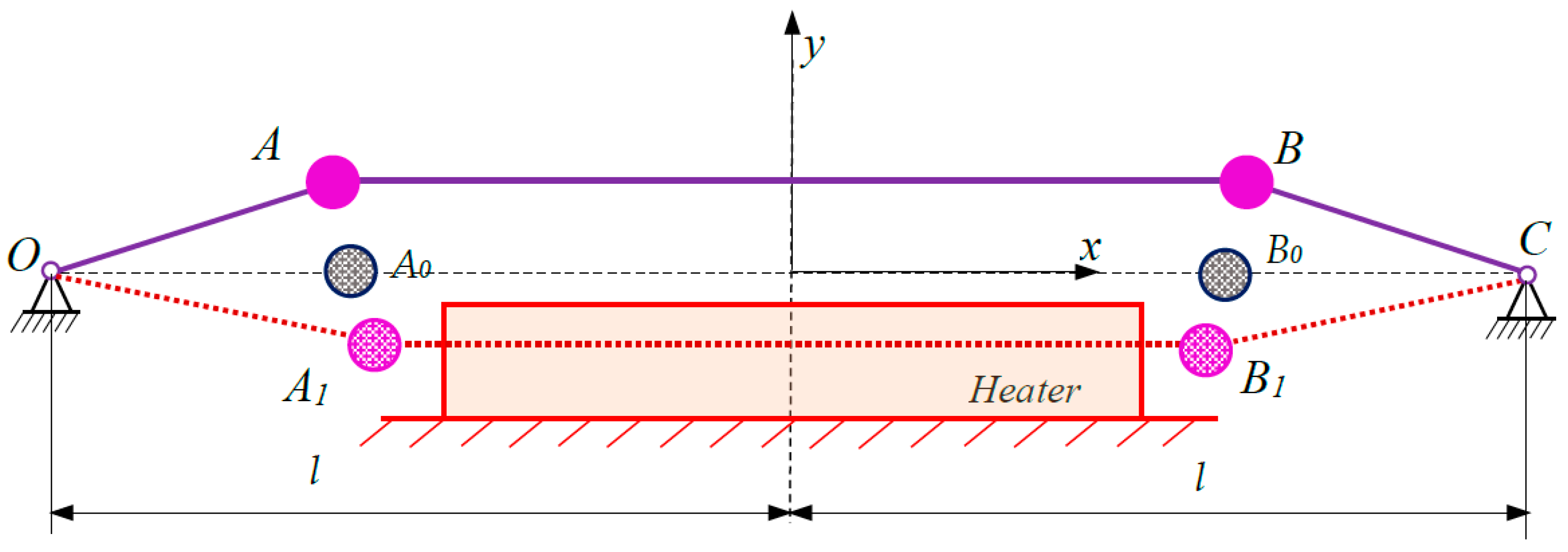
Figure 1. Scheme of the self-exiting thermomechanical oscillator.
Actuators 13 00182 g001
Figure 2. Experimental system for studying the heater’s thermal field: (a) top view photo; (b) close- view of the inductive position sensor (5) and the dial gauge (4); (c) close-view of the movable thermocouple (1), the thermocouple of the heater (2), and the heater (3); (d) block diagram. (1) Movable thermocouple; (2) heater thermocouple; (3) heater; (4) dial gauge; (5) inductive position sensor.
Actuators 13 00182 g002aActuators 13 00182 g002b
Figure 3. Experimental and approximated SMA filament temperature distribution along the y coordinate: (a) for a heater temperature of 60 °C; (b) for a heater temperature of 67 °C; (c) for a heater temperature of 78 °C.
Actuators 13 00182 g003
Figure 4. Experimental system for measuring the displacements of spheres in two perpendicular directions: (a) top view; (b) close-view of the inductive sensor 2 for x-position, and the inductive sensor 5 for y position; (c) close-view of the SMA filament (1), the heater (3), and the two masses (4); (d) block diagram. (1) SMA filament; (2) inductive x-axis position sensor; (3) heater; (4) sphere; (5) inductive y-axis position sensor; (6) support.
Actuators 13 00182 g004
Figure 5. Oscillations along the x-axis at sphere masses of 0.012 kg, a 5% pre-stretch, and a heater temperature of 80 °C: (a) experimental data; (b) dynamic model data.
Actuators 13 00182 g005
Figure 6. Oscillations along the y-axis for sphere masses of 0.012 kg, a pre-stretch of 5%, and a heater temperature of 80 °C: (a) experimental data; (b) dynamic model data.
Actuators 13 00182 g006
Table 1. Values of the parameters of the system of differential equations.
ParameterSymbolValueUnit
Half-support distancel0.026m
NiTi filament half lengthls0.25m
Mass of a spherem0.012kg
Gravity accelerationg9.81m/s2
Lengths of NiTi filament end sections l 10 = O A 0 l 30 = B 0 C 0.14m
Length of the middle section of the NiTi filament l 20 = A 0 B 0 0.24m
Diameter of NiTi filamentds0.00025m
Young’s modulus for NiTi in fully twinned martensite * E m 21.7GPa
Young’s modulus for NiTi in partially twinned martensite * E T 0.56GPa
Young’s modulus for NiTi in detwinned martensite * E d 11.1Gpa
Young’s modulus for NiTi in austenite * E a 55.5Gpa
Yield strain for twinned NiTi in martensite * ε m y 0.0024
Minimum strain of twinned NiTi in martensite * ε m d 0.0044
Starting austenite temperature of NiTi * A S 55.99°C
Final austenite temperature of NiTi * A f 64.05°C
Starting martensitic temperature of NiTi * M s 25.4°C
Final martensitic temperature of NiTi * M f 21.44°C
Austenite correction temperature b a 0.01°C
Austenite coefficient c a 1.95
Martensitic correction temperature b m 0.01°C
Martensitic coefficient c m 2.17
Start position of maximum temperature y e 0.0095m
End position of maximum temperature y f 0.023m
Room temperature T 0 20°C
Maximum temperature of NiTi filament T h 70°C
Longitudinal damping coefficientβx0.00042kg/s
Transverse damping coefficientβy0.0014kg/s
* The NiTi properties in Table 1 were obtained from experimental data published in [35].
Disclaimer/Publisher’s Note: The statements, opinions and data contained in all publications are solely those of the individual author(s) and contributor(s) and not of MDPI and/or the editor(s). MDPI and/or the editor(s) disclaim responsibility for any injury to people or property resulting from any ideas, methods, instructions or products referred to in the content.