Abstract
Due to its high power-to-weight ratio, low weight, and silent operation, shape memory alloy (SMA) is widely used as a muscle-like soft actuator in intelligent bionic robot systems. However, hysteresis nonlinearity and multi-valued mapping behavior can severely impact trajectory tracking accuracy. This paper proposes an adaptive nonsingular fast terminal sliding mode control (ANFTSMC) scheme aimed at enhancing position tracking performance in SMA-actuated systems by addressing hysteresis nonlinearity, uncertain dynamics, and external disturbances. Firstly, a simplified third-order actuator model is developed and a variable gain extended state observer (VGESO) is employed to estimate unmodeled dynamics and external disturbances within finite time. Secondly, a novel nonsingular fast terminal sliding mode control (NFTSMC) law is designed to overcome singularity issues, reduce chattering, and guarantee finite-time convergence of the system states. Finally, the ANFTSMC scheme, integrating NFTSMC with VGESO, is proposed to achieve precise position tracking for the prosthetic hand. The convergence of the closed-loop control system is validated using Lyapunov’s stability theory. Experimental results demonstrate that the external pulse disturbance error of ANFTSMC is 8.19°, compared to 19.21° for the comparative method. Furthermore, the maximum absolute error for ANFTSMC is 0.63°, whereas the comparative method shows a maximum absolute error of 1.03°. These results underscore the superior performance of the proposed ANFTSMC algorithm.
1. Introduction
Shape memory alloy (SMA) is a specialized smart material renowned for its lightweight nature, high power-to-weight ratio, low driving voltage, self-sensing capabilities, and silent operation. These characteristics make SMA an attractive choice for applications such as robotic fingers or hands, where it functions as an artificial muscle or linear actuator [1,2,3,4]. SMA can transition between two crystal structures depending on temperature and stress: the martensite phase and the austenite phase. During this phase transformation, SMA exhibits hysteretic nonlinearity and multi-valued mapping due to variations in the starting and finishing transition temperatures. This hysteretic behavior presents challenges for precise control. Key factors affecting these hysteresis characteristics include the driving signal amplitudes, frequency, external load, and environmental temperature.
To achieve accurate tracking of the SMA-based actuator system, it is crucial to describe the hysteresis behavior accurately. Conventional mathematical models for hysteresis are divided into differential-based models and operator-based models. Differential-based models are often developed by considering the physical phase transition process of SMA. The most popular models are the exponential phase transition model [5] and the cosine phase transition model [6]. However, such models are often heavily simplified by using fixed parameters and a single load, which leads to low modeling accuracy. On the other hand, operator-based models utilize operators to match hysteresis without considering the physical phase transition process. The most popular operator-based models include the Preisach model [7], the Prandtl–Ishlinskii model, and their related generalized or modified models [8,9]. Due to the complex dynamic properties, numerous operators are used to describe the hysteresis, which increases the number of adjusting parameters and further burdens the computer. In addition to the above two models, neural networks (NN) are often used to describe the dynamic characteristics of SMA [10,11]. These methods utilize parameter recognition to achieve data fitting. However, due to the large number of factors affecting the hysteresis nonlinearity of SMA, it is difficult to fully establish a complete training set, thereby making it challenging to ensure the accuracy of the model.
To compensate for the unmodeled dynamics of the SMA-actuated system, a possible approach is to accurately estimate these dynamics and compensate for them. By lumping the parameter uncertainty, unmodeled dynamics, and external disturbances as the total disturbance, the extended state observer (ESO) is an extremely efficient method for estimating the total disturbance and has been widely applied to nonlinear hysteresis systems [12,13,14]. To alleviate the issues of parameter adjustment and nonlinear function selection, a high-gain linear ESO is proposed [15,16], but its transient performance and estimation accuracy are unsatisfactory. To improve the transient performance and estimation accuracy, a time-varying ESO is proposed [17,18]. However, the time-varying gain is dependent on time and does not dynamically adjust based on the observation error. Therefore, it is crucial to design an error-driven variable-gain extended state observer (VGESO) to enhance the transient performance and improve the estimation accuracy. Gu proposed a generalized VGESO and proved that the estimation errors exponentially converge to a specific region [19].
Another way to mitigate the negative effects of hysteresis is to design robust control algorithms, such as backstepping control [20,21], fuzzy control [22,23], adaptive control [24,25], neural network control [26,27,28], and sliding mode control (SMC) [29,30]. SMC is a typical robust control method due to its insensitivity to parameter variations and external perturbations. Although SMC can ensure that the system states reach the equilibrium point, it cannot guarantee convergence in finite time. Nonlinear sliding mode control, also known as terminal sliding mode control (TSMC), can stabilize the system in finite time [31,32]. The fast terminal sliding mode control (FTSMC) algorithm can further enhance the convergence rate when the system states are far from the equilibrium points [33]. Due to the negative fractional power term in the sliding variable, these algorithms may encounter singularity problems. The nonsingular fast terminal sliding mode control (NFTSMC) algorithm was proposed to avoid such singularities [34,35]. Additionally, NFTSMC guarantees that the system converges to a stable state in finite time while reducing chattering. However, all of the aforementioned algorithms assume that the upper bound of system uncertainty is known. In practical applications, the exact upper bound is often unknown. Therefore, accurately estimating external disturbances and uncertain dynamics is crucial for achieving precise trajectory tracking control.
Based on the aforementioned error-driven VGESO and NFTSM theories, this paper proposes an adaptive nonsingular fast terminal sliding mode control (ANFTSMC) scheme to address the trajectory tracking control challenge of a prosthetic hand actuated by SMA, which exhibits time-varying parameters and hysteretic nonlinearity. The ANFTSMC scheme comprises two main components: NFTSM and error-driven VGESO. This scheme effectively estimates unmodeled dynamics and external disturbances, facilitates the rapid convergence of system states to the equilibrium point within finite time, and reduces chattering. The primary contributions of this paper are as follows: (i) A feasible, simplified third-order actuator model is constructed and an error-driven VGESO is introduced to estimate the lumped disturbance within a fixed time. (ii) A new ANFTSMC algorithm is proposed to address the effects of hysteresis nonlinearity, time-varying parameters, and external disturbances. The application of Lyapunov’s stability theory confirms that the system states will converge to a specific region within finite time.
The remainder of this paper is organized as follows. Section 2 outlines the experimental setup of a single-degree-of-freedom prosthetic finger actuated by SMA, constructs the mathematical model, designs the error-driven VGESO, verifies the Lyapunov stability analysis, proposes the ANFTSMC algorithm, and assesses the stability analysis for finite-time convergence. In Section 3, comparison experiments are conducted to demonstrate the effectiveness of the proposed scheme for the prosthetic finger. The ANFTSMC algorithm is also applied to the prosthetic hand and its feasibility is further validated. Finally, Section 4 presents the conclusions.
2. Materials and Methods
2.1. Experimental Setup
The experimental setup of a single-degree-of-freedom prosthetic finger is shown in Figure 1. The finger joint uses a rope-driven mechanism. Its movement and power are provided by an SMA actuator. Structurally, one end of the SMA actuator is connected to a tension sensor while the other end is attached to the finger joint via an insulated wire. In this setup, the SMA actuator employs resistance heating. When the driving force generated by the SMA actuator exceeds the elastic force of the spring at the finger joint, the finger joint bends. The alloy wire is cooled by air, and the finger joint returns to its original position due to the spring’s force. The alloy wire is a Flexinol wire actuator produced by Dynalloy, Inc., with an austenite finish temperature of 90 °C. It has a diameter of 0.1 mm and a length of 340 mm. Its resistance value is 126 . The output position signal is detected by the encoder. The input and output signals are processed by the Beckhoff terminal module and communicated with the Beckhoff industrial personal computer. To prevent overheating of the SMA actuator, the maximum input current is set to 0.4 A and the sampling frequency is set to 200 Hz throughout the experiment. The ambient temperature is 24 °C.
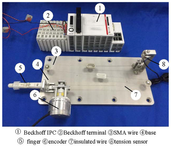
Figure 1.
The finger experiment setup of the SMA actuated system.
2.2. Mathematical Model
The mathematical model of the prosthetic finger comprises a heat transfer model, a phase transformation model, a constitutive model, and a dynamic model.
2.2.1. Heat Transfer Model
According to the first law of thermodynamics, a heat transfer model can be obtained as follows:
where m, , and represent the mass, resistance value, and heat dissipation area of the SMA wire per unit length, respectively. is the specific heat capacity. is input current. is the coefficient of heat conduction. is the SMA temperature. is the ambient temperature, °C.
2.2.2. Phase Transformation Model
Both temperature and stress can induce phase transformations in SMA between the martensite and austenite phases. The combined effects of temperature and stress determine the extent of these transformations. Experimental results from the literature [36] show that, under isostress conditions, martensite transforms into austenite as the temperature increases, with a greater degree of transformation occurring at higher temperatures, provided the temperature does not exceed the austenite finish temperature (). Conversely, as the temperature decreases, the reverse transformation occurs. At a constant temperature, a reduction in stress leads to the transformation of martensite into austenite, with the degree of transformation increasing as the stress decreases. Similarly, as stress increases, the transformation reverses. According to the enhanced phenomenological model [36], the phase transformation models and conditions can be expressed as follows.
The transformation equation from martensite to austenite is as follows:
where represents the volume fraction of martensite , where indicates a fully martensitic state while indicates fully in austenite; is before the transformation from martensite to austenite; is the austenite start temperature; is the austenite finish temperature; is the stress; ; represents the curve fitting parameter; and .
The transformation equation from austenite to martensite is as follows:
where is before the transformation from austenite to martensite, is the martensite start temperature, is the martensite finish temperature, , is the curve fitting parameter, and .
2.2.3. Constitutive Model
Based on the constitutive relationship model proposed by Tanaka [37], the output stress of SMA is related to temperature , strain , and martensite volume fraction . The expression is as follows:
where E, , and represent Young’s modulus, transformation tensor, and thermal elastic modulus, respectively. E = 51.5 × 10⁹, Ωm = − 2.06 × 10⁹, and .
2.2.4. Dynamic Model
According to the theorem of momentum, the dynamic model of the prosthetic finger joint is expressed as follows:
where J is the moment of inertia; is the joint angle; and and are the active torque and the resistance torque, respectively. , where is the cross-sectional area of SMA wire and r is the output force arm. , where is the spring resistance, is the resistance arm, and c is the viscous damping coefficient.
Combining the heat transfer model, the phase transformation model, the constitutive model, and the dynamic model, the mathematical model of the prosthetic finger can be expressed as the following state equation:
where is the state vector of system, and , , and represent angle, angular velocity, and angular acceleration, respectively. y is the system output; and are the functions of and the temperature .
To obtain accurate system model parameters, this paper employs a two-step least squares parameter identification method. The detailed identification steps can be found in the previous literature [38]. The exact parameter values of the system model are shown in Table 1.

Table 1.
List of system model parameters.
2.3. State Estimation
2.3.1. VGESO
Let be defined as a new extended state variable, where , is the estimated value of , and represents the total disturbance of the system, which includes parametric perturbations, unmodeled dynamics, and external disturbances.
Assumption 1.
The lumped uncertainty is differentiable, and its derivative is given by , where is bounded, .
Then, the extended state equation can be obtained as follows:
According to the extended state observer theory, an error-driven VGESO is designed as follows [19]:
where the parameters of and are the estimated values of and the observer gains, respectively. represents the observer errors, and is the variable gain defined as , where is the speed factor used to increase the response speed and limit the maximum value of the variable gain , and is a positive scalar. It is evident that satisfies .
2.3.2. Convergence of VGESO
According to for , and by combining (7) with (8), the estimated error system can be expressed as
where , , , and .
Obviously, the error-driven matrix is not always a Hurwitz matrix. To prove the observer is convergent, let be defined in the following form:
where , , , , , , and .
If the value of is properly chosen, then the matrix becomes a Hurwitz matrix. Consequently, there exists a symmetric positive definite matrix that satisfies the following Lyapunov equation.
Choose the Lyapunov function ; then, the following inequality exists:
where and denote the minimal and maximal eigenvalues of the matrix , respectively.
Define
where is a scalar.
There is the following inequality:
where ; and denote the minimal and maximal eigenvalues of , respectively; ; and .
Therefore, for a given parameter , if is chosen to satisfy the following relationship:
then the matrix (12) is a negative definite matrix.
The time derivative of is
where denotes the minimal eigenvalue of matrix .
From Equation (13), we can obtain
Based on the relationship between and , we can derive
is ultimately convergent and it satisfies the bound .
Lemma 1
([39]). Consider the system (9), suppose there exists a positive definite function and an open neighborhood of the origin such that , where , , and . Then, can converge to zero in a finite time . The settling time is bounded by .
According to Lemma 1, can converge to a region near the origin within a finite time. Considering the relationship between and , we can conclude that will ultimately converge to a region around the origin within a finite time.
2.4. Controller Design and Stability Analysis
In this section, an ANFTSMC scheme is proposed to address the unmodeled dynamics, hysteresis nonlinearity, and external disturbances in the prosthetic finger system. The control framework of the ANFTSMC scheme [39] is shown in Figure 2.

Figure 2.
The block diagram of the ANFTSMC scheme.
2.4.1. Controller Design
Assumption 2.
The reference signal is a function that is twice differentiable with respect to time t.
Firstly, define the error terms: , , and .
According to (7), the error dynamics of the system can be described as
A NFTSMC sliding surface is designed as follows:
where , , , , , and are all positive constants, with , , and satisfying the conditions and .
Taking the derivative of (19), we have
To guarantee that the system states ultimately track the reference trajectory, a novel ANFTSMC law is designed as follows:
where
where
where and denotes a small positive constant.
2.4.2. Stability Analysis
In order to prove that the closed-loop system can converge in a finite time, a Lyapunov function candidate is chosen as and the derivative of with respect to time is
By substituting the control law (23) into the above equation, we can obtain
where .
When , and by choosing so that the inequality is satisfied, we can obtain
where and .
From Lemma 1, we can verify that the ANFTSM manifold s converges to a region near the origin within a finite time.
Through transformation, (19) can be rewritten as follows:
The above expression is in the same form as Formula (15) in the literature [40]. Thus, if , the angular error will converge to a region where with a finite time.
Similarly, if , then the angular velocity error will converge to a region where within a finite time.
In the same way, if , then the acceleration error will converge to a region where within a finite time.
3. Results
3.1. Model Validation
To demonstrate the superiority of the VGESO, a comparative experiment is conducted between the VGESO and the nominal model. Considering both estimation accuracy and chattering, the parameter values of the VGESO are selected as , , , , , and . The sinusoidal excitation signal of the system is given by , where the driving frequencies are 1/50 Hz, 1/30 Hz, 1/20 Hz, and 1/15 Hz, respectively. The frequency of the excitation signal reflects the rate of temperature change in the SMA actuator, which influences the hysteresis characteristics. Figure 3, Figure 4, Figure 5 and Figure 6 show the comparative results of the actual output, the nominal model, and the VGESO. From Figure 3, Figure 4, Figure 5 and Figure 6, it can be observed that the VGESO demonstrates better estimation accuracy and faster estimation speed compared to the nominal model. Additionally, as the frequency increases, the accuracy of the nominal model decreases. The quantitative analysis of RMSE is presented in Table 2, which further confirms that the VGESO offers significant advantages and effectively compensates for model errors.
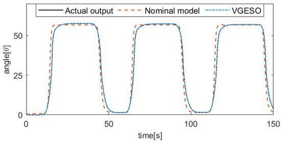
Figure 3.
Comparative result among the actual output, nominal model, and VGESO at f = 1/50 Hz.
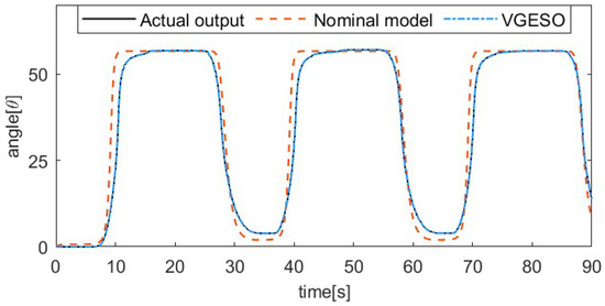
Figure 4.
Comparative result among the actual output, nominal model, and VGESO at f = 1/30 Hz.
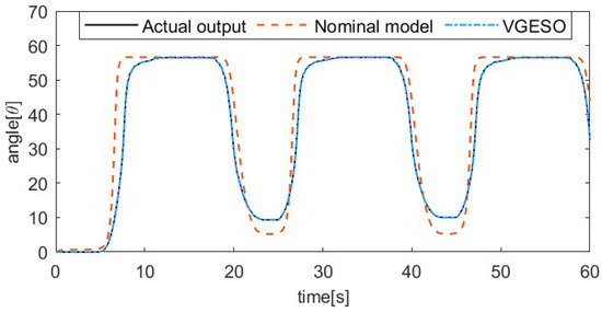
Figure 5.
Comparative result among the actual output, nominal model, and VGESO at f = 1/20 Hz.
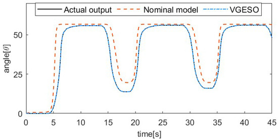
Figure 6.
Comparative result among the actual output, nominal model, and VGESO at f = 1/15 Hz.

Table 2.
The index of RMSE.
3.2. Experimental Validation on the SMA Actuator-Based Finger Setup
To verify the effectiveness of the proposed control algorithm, we compare the proposed ANFTSMC with SMC based on LESO (ESMC). In the comparison experiment, the same sliding mode manifold is used for both algorithms. The control parameters are selected as , , , , , , , , , and . To demonstrate the dynamic trajectory tracking performance, we have designed two types of trajectory tracking experiments: one with multi-step trajectory tracking and the other with constant value trajectory tracking under variable load disturbance.
3.2.1. Set-Point Tracking
Figure 7, Figure 8, Figure 9 and Figure 10 show the comparative results between the ANFTSMC scheme and the ESMC scheme. Specifically, Figure 7 depicts the multi-step tracking trajectory. Figure 8 illustrates the corresponding tracking error. Figure 9 displays the control input for the two schemes. Figure 10 shows the performance of the sliding mode manifold. It is evident that both schemes can track multi-step trajectories. However, the proposed ANFTSMC scheme exhibits a faster convergence rate during value increases and decreases. This indicates that the ANFTSMC scheme can more quickly compensate for the total disturbances during the transition between martensite and austenite. It can be observed that the proposed scheme effectively reduces chattering compared to the ESMC scheme. This further demonstrates that the ANFTSMC method possesses strong capabilities to estimate the total disturbance in real time. Furthermore, Figure 10 shows that the proposed method enables the system states to converge more quickly to the equilibrium position.
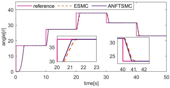
Figure 7.
Comparing the multi-step tracking trajectory of two methods.
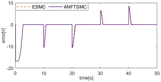
Figure 8.
Comparing the multi-step tracking error of two methods.
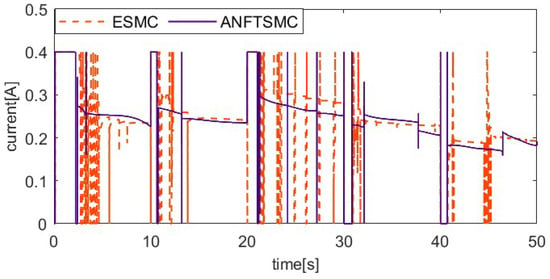
Figure 9.
Comparing control input of two methods.
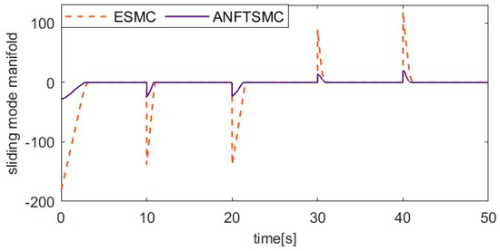
Figure 10.
Comparing the sliding mode manifold of two methods.
3.2.2. Load Variations and Disturbance Rejection
The load factor can affect the dynamic properties of the SMA prosthetic finger, as different loads can result in different hysteresis loops. To verify the ability of the proposed method to resist varying load disturbances, the system applies an additional 50 g load to the fingertip after the 10th second during the 20° setting value tracking experiment, unloads the 50 g load at the 20th second, applies a 150 g load at the 30th second, and then unloads the 150 g load at the 40th second. To further verify the robustness of the control system, an external pulse disturbance is applied to the system during the tracking of the setting value. To ensure load consistency, the coupling is rotated 15° counterclockwise at the 50th second, enabling the alloy wire to achieve temporary relaxation. Figure 11, Figure 12, Figure 13 and Figure 14 show the setting value tracking trajectory experiments with load disturbances. Figure 11 and Figure 12 demonstrate the ability of the two schemes to reject load disturbances. It can be seen that the ANFTSMC scheme can quickly converge to the reference trajectory under the condition of increasing or decreasing loads, with small errors and strong disturbance rejection ability. However, while the ESMC scheme can ensure the system’s stability, the tracking error is larger. The external pulse disturbance error of the ESMC scheme is 19.21°, which is more than twice as large as that of the ANFTSMC scheme (8.19°). Figure 13 shows the control input, and it is obvious that the proposed ANFTSMC scheme exhibits less chattering than the ESMC scheme. Furthermore, from Figure 14, it can be further observed that the ANFTSMC scheme has greater robustness.
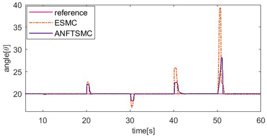
Figure 11.
Comparing tracking trajectory of two methods under variable loads.
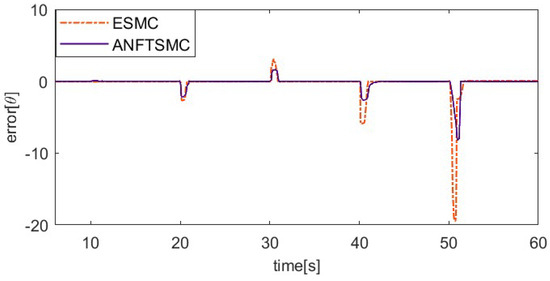
Figure 12.
Comparing trajectory tracking error of two methods under variable loads.
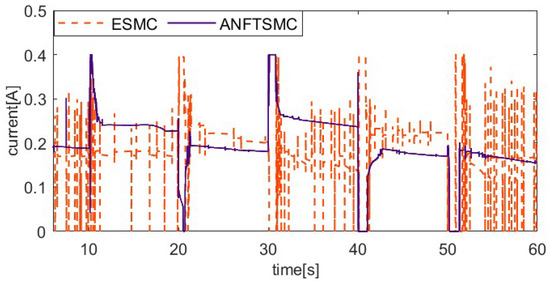
Figure 13.
Comparing control input of two methods under variable loads.
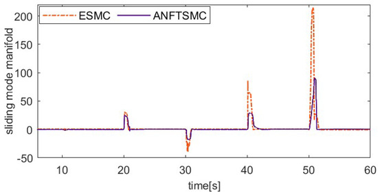
Figure 14.
Comparing sliding mode manifold of two methods under variable loads.
3.3. Experiments on SMA Actuator-Based Prosthetic Hand Robot System
3.3.1. The Experimental Setup
After verifying the proposed ANFTSMC algorithm, we designed a prosthetic hand robot system based on the SMA actuator, as shown in Figure 15. This dexterous hand robot consists of five fingers, and each finger is controlled by an individual SMA actuator. The SMA actuators are installed in the forearm. In order to enhance control over the SMA wire, a displacement feedback mechanism has been established. The controller is a Beckhoff industrial personal computer, and analog communication is conducted through the Beckhoff terminal module. The sample frequency is set to 200 Hz. To prevent overheating of the SMA actuator, the maximum input current value is set to 0.4 A.
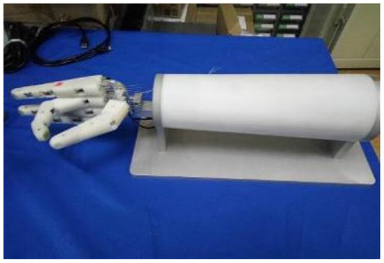
Figure 15.
Prosthetic hand robot system based on SMA actuator.
3.3.2. Position Tracking Experiments of the Prosthetic Hand System Based on ANFTSMC
In this section, we select the index finger part of the prosthetic hand robot as the controlled object, and we compare the position response curves of the proposed ANFTSMC algorithm with the ESMC method under step desired signals as well as sinusoidal desired signals. Meanwhile, to further demonstrate the control effects of the two control algorithms, we also compare the error tracking curves once the system reaches a steady state.
The sinusoidal response comparison curve and error comparison curve of the two algorithms are shown in Figure 16 and Figure 17. The reference signal is . Because the pre-tension affects the dynamic characteristics of SMA, the index finger is pre-tightened in this part of the tracking experiment, with an initial bending angle of 5°. From Figure 16 and Figure 17, we can find that the proposed ANFTSMC algorithm can compensate for the change in dynamic characteristics, having a smaller steady-state error and less chattering. Only considering the steady state of the system, the maximum absolute error of the ESMC is 1.03° and the maximum absolute error of the ANFTSMC is 0.63°. Therefore, the tracking performance of the ANFTSMC is better.
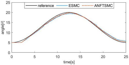
Figure 16.
Position tracking result for sinusoidal signal tracking.
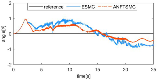
Figure 17.
System steady-state error for sinusoidal signal tracking.
The step signal tracking comparative curves are displayed in Figure 18 and Figure 19. From the experimental results, it can be observed that the proposed ANFTSMC algorithm exhibits a small overshoot value, specifically 0.59°. In contrast, the overshoot value of the ESMC algorithm is 1.19°. Meanwhile, when the system reaches a stable state, the proposed ANFTSMC algorithm ensures stability with minimal chattering or vibration. However, the ESMC algorithm experiences continuous chattering. Therefore, the prosthetic hand robot system demonstrates superior control performance when using the ANFTSMC algorithm.
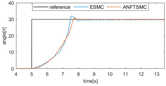
Figure 18.
Position tracking result for step signal tracking.
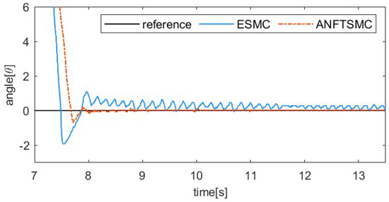
Figure 19.
System steady-state error for step signal tracking.
3.3.3. Grasp Experiments
To evaluate the flexibility and grasping capabilities of the SMA-actuated prosthetic hand robot, experiments focusing on typical activities of daily living were carried out in this part. According to the different objects grasped, the grip patterns are classified into power grip, precision grip, and lateral grip [41]. Due to the structural limitations of the prosthetic hand used in this study, lateral grip experiments are not included as part of the experimental content in this paper. We conducted tests and experiments with various commonly used postures in daily living, along with 50 grasps of multiple types of items, achieving a grasping success rate of over 95%. In Figure 20, we display the pointing posture, OK posture, cylindrical grip, spherical grip, and precision grip from left to right. The pointing posture is a frequently used action in daily living, such as pressing a switch, while the OK posture expresses agreement. The cylindrical grip and spherical grip belong to power grips. The diameters of the cylinder and the sphere are 6.3 cm and 6 cm, respectively. The object intended for precision grip is a standard competition-grade table tennis ball. As shown, the prosthetic hand is capable of performing different hand gesture movements and achieving stable grasping of different objects. Therefore, the effectiveness of the proposed ANFTSMC algorithm is further confirmed.

Figure 20.
Common postures and grip patterns: (a) pointing posture; (b) OK posture; (c) cylindrical grip; (d) spherical grip; (e) precision grip.
4. Conclusions
A novel ANFTSMC method, which is a combination of NFTSMC and VGESO, is proposed to estimate the unmodeled dynamics, compensate for the hysteresis nonlinearity, and improve the control performance of a prosthetic finger actuated by SMA. The NFTSMC scheme can avoid singular problems and mitigate chattering. The VGESO is designed based on errors to dynamically adjust gains. It can accurately estimate the unmodeled dynamics and disturbance within finite time, thus enhancing the robustness of the system. Lyapunov’s stability theory proves the convergence of the closed-loop system in finite time. By comparing it with the ESMC algorithm, the superiority of the proposed ANFTSMC algorithm in terms of control is demonstrated. Meanwhile, the ANFTSMC algorithm is also applied to a prosthetic hand robot system, and the experimental results further demonstrate the effectiveness of the proposed method. In the future, we will enhance the control performance by reducing the adverse effects of actuator saturation.
Author Contributions
Conceptualization, X.L.; methodology, X.L. and W.Z.; software, X.F.; validation, X.L. and E.S.; data curation, E.S. and M.Z.; writing—original draft preparation, X.L.; writing—review and editing, W.Z. and M.Z.; visualization, X.L. and M.Z.; supervision, B.Z.; funding acquisition, B.Z. All authors have read and agreed to the published version of the manuscript.
Funding
This work is supported by Huzhou Science and Technology Project (Grant No. 2023YZ39) and the National Natural Science Foundation of China (Grant Nos. 62103406, 62333007 and U22A2067).
Data Availability Statement
The original contributions presented in the study are included in the article; further inquiries can be directed to the corresponding author.
Conflicts of Interest
The authors declare no conflicts of interest.
References
- Baek, H.; Khan, A.M.; Bijalwan, V.; Jeon, S.; Kim, Y. Dexterous Robotic Hand Based on Rotational Shape Memory Alloy Actuator-Joints. IEEE Trans. Med. Robot. Bionics 2023, 5, 1082–1092. [Google Scholar] [CrossRef]
- Yang, J.; Sun, S.; Yang, X.; Ma, Y.; Yun, G.; Chang, R.; Tang, S.Y.; Nakano, M.; Li, Z.; Du, H.; et al. Equipping New SMA Artificial Muscles With Controllable MRF Exoskeletons for Robotic Manipulators and Grippers. IEEE/ASME Trans. Mechatron. 2022, 27, 4585–4596. [Google Scholar] [CrossRef]
- Abondance, S.; Teeple, C.B.; Wood, R.J. A Dexterous Soft Robotic Hand for Delicate In-Hand Manipulation. IEEE Robot. Autom. Lett. 2020, 5, 5502–5509. [Google Scholar] [CrossRef]
- Deng, E.; Tadesse, Y.A. A Soft 3D-Printed Robotic Hand Actuated by Coiled SMA. Actuators 2020, 10, 6. [Google Scholar] [CrossRef]
- Tanaka, K. A Phenomenological Description on Thermomechanical Behavior of Shape Memory Alloys. J. Press. Vessel. Technol. Trans. ASME 1990, 112, 158–163. [Google Scholar] [CrossRef]
- Liang, C.; Rogers, C.A. One-Dimensional Thermomechanical Constitutive Relations for Shape Memory Materials. J. Intell. Mater. Syst. Struct. 2013, 1, 207–234. [Google Scholar] [CrossRef]
- Ge, J.Z.; Chang, L.L.; Pérez-Arancibia, N.O. Preisach-model-based position control of a shape-memory alloy linear actuator in the presence of time-varying stress. Mechatronics 2021, 73, 102452. [Google Scholar] [CrossRef]
- Feng, Y.; Yu, T. Modeling of Shape Memory Alloy Artificial Wrist Joint via Modified Prandtl-Ishlinskii Hysteresis Model. In Proceedings of the 2023 International Conference on Advanced Robotics and Mechatronics (ICARM), Sanya, China, 8–10 July 2023; pp. 1125–1130. [Google Scholar]
- Feng, Y.; Guo, J. Modeling for Magnetic Shape Memory Alloy Actuators Using a Modified Generalized Prandtl-Ishlinskii Model. In Proceedings of the 2023 IEEE International Conference on Development and Learning, Macau, China, 9–11 November 2023; pp. 144–149. [Google Scholar]
- Pei, Y.C.; Wang, B.H.; Wu, J.T.; Wang, C.Y.; Guan, J.H.; Lu, H.Q. Machine Learning Empowered Shape Memory Alloy Gripper With Displacement-Force-Stiffness Self-Sensing. IEEE Trans. Ind. Electron. 2023, 70, 10385–10395. [Google Scholar] [CrossRef]
- Feng, Y.; Liang, M.; Hu, Z. Tracking Control of Shape Memory Alloy Artificial Wrist Joint Using Sliding Mode Control Strategy Based on RBF Neural Network. In Proceedings of the 2022 International Conference on Advanced Robotics and Mechatronics (ICARM), Guilin, China, 29 November 2022; pp. 990–995. [Google Scholar]
- Qi, G.; Li, X.; Chen, Z. Problems of Extended State Observer and Proposal of Compensation Function Observer for Unknown Model and Application in UAV. IEEE Trans. Syst. Man Cybern. Syst. 2022, 52, 1037–1046. [Google Scholar] [CrossRef]
- Liu, Q.; Zhang, L.; Zhang, W. High-Order Generalized Integrator ESO-Based PLL Considering Time-Varying Disturbances. IEEE Trans. Power Electron. 2024, 39, 101–105. [Google Scholar] [CrossRef]
- Pu, Z.; Yuan, R.; Yi, J.; Tan, X. A Class of Adaptive Extended State Observers for Nonlinear Disturbed Systems. IEEE Trans. Ind. Electron. 2015, 62, 5858–5869. [Google Scholar] [CrossRef]
- Guo, B.Z.; Zhao, Z.L. On the convergence of an extended state observer for nonlinear systems with uncertainty. Syst. Control. Lett. 2011, 60, 420–430. [Google Scholar] [CrossRef]
- Zhou, J.; Ding, W.; Zhang, J.; Yi, F.; Zhang, Z.; Wu, G.; Zhang, C. A Nonlinear Active Disturbance Rejection Feedback Control Method for Proton Exchange Membrane Fuel Cell Air Supply Subsystems. Actuators 2024, 13, 268. [Google Scholar] [CrossRef]
- Ding, T.-F.; Ge, M.-F.; Liu, Z.-W.; Chi, M.; Ahn, C.K. Cluster Time-Varying Formation-Containment Tracking of Networked Robotic Systems Via Hierarchical Prescribed-Time ESO-Based Control. IEEE Trans. Netw. Sci. Eng. 2024, 11, 566–577. [Google Scholar] [CrossRef]
- Yang, H.; Sun, J.; Xia, Y.; Zhao, L. Position Control for Magnetic Rodless Cylinders with Strong Static Friction. IEEE Trans. Ind. Electron. 2018, 65, 5806–5815. [Google Scholar] [CrossRef]
- Gu, S.; Zhang, J.; Li, Y. Generalized Variable Gain ADRC for Nonlinear Systems and Its Application to Delta Parallel Manipulators. IEEE Trans. Circuits Syst. I Regul. Pap. 2023, 70, 921–930. [Google Scholar] [CrossRef]
- Yao, M.; Li, X.; Li, K. Backstepping Dynamic Surface Control of an SMA Actuator Based on Adaptive Neural Network. In Proceedings of the 2023 2nd International Conference on Innovations and Development of Information Technologies and Robotics (IDITR), Chengdu, China, 26–28 May 2023; pp. 70–77. [Google Scholar]
- Li, Z.; Li, J.; Weng, T.; Zheng, Z. Adaptive Backstepping Time Delay Control for Precision Positioning Stage with Unknown Hysteresis. Mathematics 2024, 12, 1197. [Google Scholar] [CrossRef]
- Nguyen, B.K.; Ahn, K.K. Feedforward Control of Shape Memory Alloy Actuators Using Fuzzy-Based Inverse Preisach Model. IEEE Trans. Control. Syst. Technol. 2009, 17, 434–441. [Google Scholar] [CrossRef]
- Nalini, D.; Nandakumar, A.; Sampath, A.; Dhanalakshmi, K. Fuzzy based active stiffness control of a synergistically compliant variable stiffness shape memory actuator. In Proceedings of the 2019 IEEE 5th International Conference for Convergence in Technology (I2CT), Bombay, India, 29–31 March 2019; pp. 1–5. [Google Scholar]
- Feng, Y.; Huang, X. Adaptive Fractional Order Proportional Integral Derivative Control for a Shape Memory Alloy Driven Puncture Platform. In Proceedings of the 2023 IEEE International Conference on Development and Learning (ICDL), Macau, China, 9–11 November 2023; pp. 250–255. [Google Scholar]
- Xu, S. Disturbance Observer-Based Adaptive Fault Tolerant Control with Prescribed Performance of a Continuum Robot. Actuators 2024, 13, 267. [Google Scholar] [CrossRef]
- Pan, Y.; Guo, Z.; Li, X.; Yu, H. Output-Feedback Adaptive Neural Control of a Compliant Differential SMA Actuator. IEEE Trans. Control. Syst. Technol. 2017, 25, 2202–2210. [Google Scholar] [CrossRef]
- Garriga-Casanovas, A.; Shakib, F.; Ferrandy, V.; Franco, E. Hybrid Control of Soft Robotic Manipulator. Actuators 2024, 13, 242. [Google Scholar] [CrossRef]
- Rączka, W.; Sibielak, M. Model of Shape Memory Alloy Actuator with the Usage of LSTM Neural Network. Materials 2024, 17, 3114. [Google Scholar] [CrossRef] [PubMed]
- Liu, H.S.; Cheng, Q.; Xiao, J.C.; Hao, L.N. Performance-based data-driven optimal tracking control of shape memory alloy actuated manipulator through reinforcement learning. Eng. Appl. Artif. Intell. 2022, 114, 105060. [Google Scholar] [CrossRef]
- Zeng, X.; Zhang, X.; Nan, F. The Sliding Mode Control for Piezoelectric Tip/Tilt Platform on Precision Motion Tracking. Actuators 2024, 13, 269. [Google Scholar] [CrossRef]
- Çavuş, B.; Aktaş, M. A New Adaptive Terminal Sliding Mode Speed Control in Flux Weakening Region for DTC Controlled Induction Motor Drive. IEEE Trans. Power Electron. 2024, 39, 449–458. [Google Scholar] [CrossRef]
- Artetxe, E.; Barambones, O.; Calvo, I.; del Rio, A.; Uralde, J. Combined Control for a Piezoelectric Actuator Using a Feed-Forward Neural Network and Feedback Integral Fast Terminal Sliding Mode Control. Micromachines 2024, 15, 757. [Google Scholar] [CrossRef]
- Qin, C.; Zhang, Z.; Fang, Q. Adaptive Backstepping Fast Terminal Sliding Mode Control With Estimated Inverse Hysteresis Compensation for Piezoelectric Positioning Stages. IEEE Trans. Circuits Syst. II Express Briefs 2024, 71, 1186–1190. [Google Scholar] [CrossRef]
- Yogi, S.C.; Behera, L.; Nahavandi, S. Adaptive Intelligent Minimum Parameter Singularity Free Sliding Mode Controller Design for Quadrotor. IEEE Trans. Autom. Sci. Eng. 2024, 21, 1805–1823. [Google Scholar] [CrossRef]
- Lin, F.J.; Wang, P.L.; Hsu, I.M. Intelligent Nonsingular Terminal Sliding Mode Controlled Nonlinear Time-Varying System Using RPPFNN-AMF. IEEE Trans. Fuzzy Syst. 2004, 32, 1036–1049. [Google Scholar] [CrossRef]
- Elahinia, M.H.; Ahmadian, M. An Enhanced SMA Phenomenological Model: II. The Experimental Study. Smart Mater. Struct. 2005, 14, 1309–1319. [Google Scholar] [CrossRef][Green Version]
- Tanaka, K. A thermomechanical sketch of shape memory effect: One-dimensional tensile behavior. Res. Mech. 1986, 18, 251–263. [Google Scholar]
- Li, X.; Zhang, B.; Zhang, D.; Zhao, X.; Han, J. Disturbance Compensation-based Output Feedback Adaptive Control for Shape Memory Alloy Actuator System. Int. J. Adv. Robot. Syst. 2021, 18, 1–13. [Google Scholar] [CrossRef]
- Zou, H.M.; Zhang, G.S.; Hao, J. Nonsingular Fast Terminal Sliding Mode Tracking Control for Underwater Glider with Actuator Physical Constraints. ISA Trans. 2024, 146, 249–262. [Google Scholar] [CrossRef] [PubMed]
- Li, J.; Du, H.; Cheng, Y.; Wen, G.; Chen, X.; Jiang, C. Position Tracking Control for Permanent Magnet Linear Motor via Fast Nonsingular Terminal Sliding Mode Control. Nonlinear Dyn. 2019, 97, 2595–2605. [Google Scholar] [CrossRef]
- Feix, T. Anthropomorphic Hand Optimization Based on a Latent Space Analysis. Ph.D. Thesis, Technical University of Vienna, Vienna, Austria, 2011. [Google Scholar]
Disclaimer/Publisher’s Note: The statements, opinions and data contained in all publications are solely those of the individual author(s) and contributor(s) and not of MDPI and/or the editor(s). MDPI and/or the editor(s) disclaim responsibility for any injury to people or property resulting from any ideas, methods, instructions or products referred to in the content. |
© 2024 by the authors. Licensee MDPI, Basel, Switzerland. This article is an open access article distributed under the terms and conditions of the Creative Commons Attribution (CC BY) license (https://creativecommons.org/licenses/by/4.0/).