Abstract
In this study, we integrated virtual reality (VR) goggles and a motor imagery (MI) brain-computer interface (BCI) algorithm with a lower-limb rehabilitation exoskeleton robot (LLRER) system. The MI-BCI system was integrated with the VR goggles to identify the intention classification system. The VR goggles enhanced the immersive experience of the subjects during data collection. The VR-enhanced electroencephalography (EEG) classification model of a seated subject was directly applied to the rehabilitation of the LLRER wearer. The experimental results showed that the VR goggles had a positive effect on the classification accuracy of MI-BCI. The best results were obtained with subjects in a seated position wearing VR, but the seated VR classification model cannot be directly applied to rehabilitation triggers in the LLRER. There were a number of confounding factors that needed to be overcome. This study proposes a cumulative distribution function (CDF) auto-leveling method that can apply the seated VR model to standing subjects wearing exoskeletons. The classification model of seated VR had an accuracy of 75.35% in the open-loop test of the LLRER, and the accuracy of correctly triggering the rehabilitation action in the closed-loop gait rehabilitation of LLRER was 74%. Preliminary findings regarding the development of a closed-loop gait rehabilitation system activated by MI-BCI were presented.
1. Introduction
Human–robot cooperative control (HRCC) based on physiological signals can be categorized into two types, passive and active training, according to whether or not the user’s voluntary intention is taken into account in the rehabilitation process [1]. It has been investigated and proved that the active training approach, which promotes the patient’s voluntary intention to be involved during rehabilitation training, is a highly effective and successful technique for neurorehabilitation and motor recovery [2]. The source of control for active training often comes from the subject’s physiologic signals, including surface electromyography (sEMG) [3,4,5] and electroencephalography (EEG) signals [6,7,8,9]. Both signals can improve the level of control for active training. One of the most difficult problems that still requires attention is the development of robust and efficient algorithms to determine the user’s motion intention and to generate the correct trajectories with the wearable robots [10].
Motor imagery (MI) and action observation (AO) have traditionally been recognized as two separate techniques. Both can be used in combination with physical exercises to enhance motor training and rehabilitation outcomes, and these two independent techniques have been shown to be largely effective. There is evidence suggesting that observation, imagery, and synchronized imitation are associated with a broad increase in cortical activity relative to rest [11]. As both MI and AO may be effective in improving motor function in stroke survivors, and there is evidence that MI ability can be improved after AO, the AO + MI combination may therefore be effective in improving motor function in stroke rehabilitation [12].
AO + MI can be categorized into three different states, namely congruent AO + MI, coordinative AO + MI, and conflicting AO + MI. Congruent AO + MI is when the observer imagines themselves performing the content of the action while observing another person performing the same type of action [13]. Taube, Wolfgang, and colleagues conducted a series of studies on lower limbs in congruent AO + MI [14]. Through fMRI measurements, it was learned that the highest and most widespread levels of activity in motor-related areas (M1, PMv and PMd, SMA, cerebellum, putamen) occurred during AO + MI, followed by MI, then AO [14]. Similar findings were observed by [15], and these studies showed that AO had enhancing effects on MI.
In recent years, augmented and virtual reality(augmented reality, AR; virtual reality, VR) have matured technologically to provide users with a higher level of immersion and presence. Together with AR/VR, BCI offers the possibility of immersive scenes through the induced illusion of artificially perceived reality. In research studies, it is possible to use AR/VR to smoothly adjust the intensity, complexity, and realism of stimuli while fully controlling the environment in which they are presented [16]. Previous studies have shown that (Q3.1) VR-based therapies have positive effects on neurological disorders and lower-limb motor rehabilitation, but the characteristics of these VR applications have not been systematically investigated [17]. Research has shown a general consensus that visual feedback is useful for reinforcing behavior [18], and it is likely that MI therapies can be used to reinforce knowledge learned in VR [19]. Recently, Ferrero et al. [20] investigated gait MI in a VR environment. They analyzed whether gait MI could be improved when subjects were provided with VR feedback instead of on-screen visual feedback. In addition, both types of visual feedback were analyzed when subjects were sitting or standing. According to Ferrero’s visual feedback from VR was associated with better classification performance in most cases, independent of the difference between subjects standing or sitting.
Although the study by Ferrero et al. was promising, the scenario design was based on the use of VR alone for visual feedback (virtual first-person perspective movement) and lacked exoskeleton-assisted limb sensory feedback as in [21,22,23,24,25]. Sensory feedback to the limbs is crucial to the rehabilitation outcome and is comparable to what a traditional physiotherapist would do to assist in the rehabilitation process. In this study, we will integrate the emerging VR technology with AO + MI techniques and lower-limb rehabilitation exoskeleton control technology to further investigate the practical application of MI-BCI combined with VR to a lower-limb rehabilitation exoskeleton robot (LLRER).
This study continued the previously developed adaptive gait MI-BCI algorithm and applied it to a series of BCI experiments [26]. The integration of VR goggles with the MI-BCI system allowed us to investigate the effect of viewpoint differences on model classification accuracy. We also integrated the VR-enhanced MI-BCI with our previously developed LLRER system [27]. Firstly, we investigated whether the VR display of first-person walking footage had a positive effect on the training of the MI-BCI model, and then further applied the classification model to the LLRER wearers. A complete closed-loop MI-BCI rehabilitation process has been observed and developed for fast application in the LLRER system developed by this study.
Four contributions were made to the integration of the VR-enhanced MI-BCI with the LLRER system:
- The proposed framework of integrating VR glasses and BCI system enables the collection of EEG in VR environment, and the quality of EEG channels can be further captured and recorded through image processing. Compared to VR devices on the market, VR goggle integration technology requires a lower development cost and can be developed using a smartphone as the screen of a head-mounted display.
- The effects of different AO contents and subject status on MI classification were preliminarily investigated.
- We also propose an open-loop automatic threshold correction procedure for MI-BCI to facilitate the application of LLRER for closed-loop gait rehabilitation in subsequent studies.
- The integration of multiple devices, the MI-BCI devices, treadmill control system, and LLRER control system were integrated through the local network, and the practicality of this integration framework was verified in the closed-loop experimental session.
2. Methods
2.1. Overall System Architecture
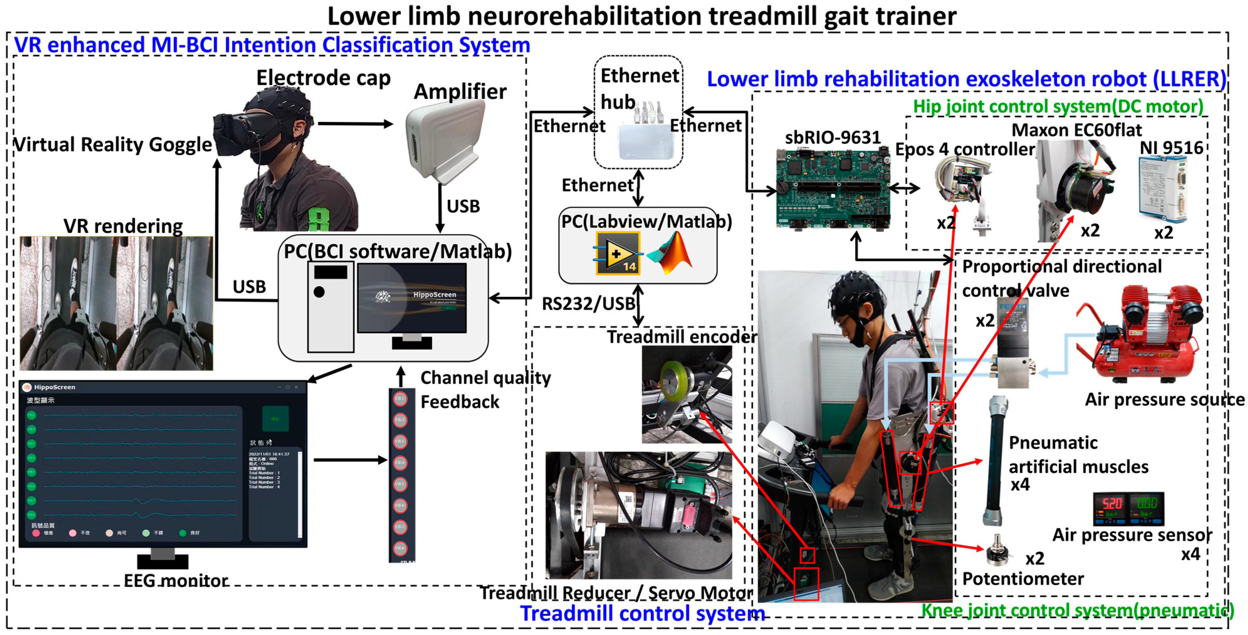
The overall system overview is shown in Figure 1. The system consists of three parts; the first part is the control of the LLRER, the second part is the treadmill control, and the third part is the integration and data collection of the VR-enhanced MI-BCI.
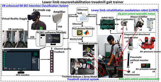
Figure 1.
Lower-limb neurorehabilitation treadmill gait trainer architecture.
A VR-enhanced MI-BCI controlled exoskeleton for lower-limb gait rehabilitation was developed. The mechanical design of the LLRER allows the leg length to be adjusted to fit different heights. The back frame was made of aluminum alloy for overall lightness and robustness. LLRER provided four degrees of freedom for the lower limbs. The knee is powered by a pneumatic actuated muscle (PAM) antagonistic actuator and the hip is powered by a DC motor with a reducer to consider the response speed and load. The exoskeleton was suspended above the treadmill by steel cables and counterweights, and the exoskeleton controller was integrated with the treadmill speed control on the program level.
Our goal is to develop an integrated neurorehabilitation system that incorporates VR goggles, an EEG brain-computer interface, and a lower-limb exoskeleton control system. The right side of Figure 1 shows the LLRER [27] developed in our previous study with treadmill synchronization control, and the left side shows the integration method of the EEG system with the MI-BCI algorithm developed in our previous study [26]. We integrated the VR goggles with the BCI system and displayed the first-person gait perspective in the VR goggles to enhance the subject’s sense of immersion through the VR goggles.
Figure 1 can be roughly divided into three major subsystems: VR-enhanced MI-BCI intention classification system, treadmill, and LLRER. The three major subsystems use the local network to integrate and communicate through TCP/IP. When the EEG signal from the user decodes the motor intention, the lower-limb gait rehabilitation system is activated through the local network.
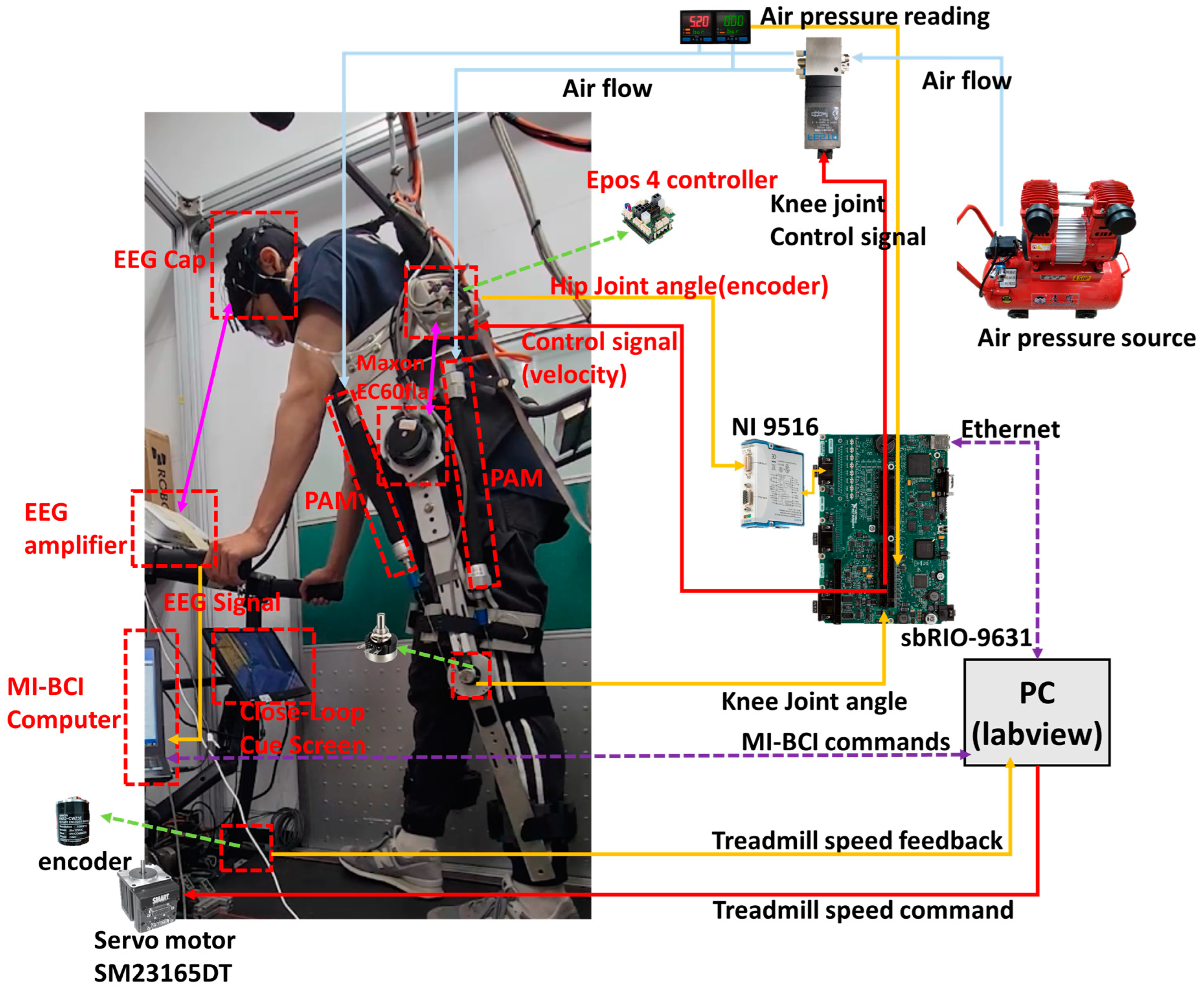
The main computing unit of the exoskeleton is sbRIO-9631. NI9516 is responsible for receiving the encoder signals from the Maxon motor, converting the current hip angle and providing it to the sbRIO-9631 for calculation. The knee joint reads the current angle of the potentiometer through the analog input, and the controller calculated the control signal to control the knee joint and hip joint through the analog output to achieve the control of the exoskeleton. As shown in Figure 2, the red arrows are the control commands, yellow represents the various instances of feedback of the exoskeleton, pink is the internal communication of the device, blue is pressurized air, and the purple dotted line is the network communication. For the reason of clarity, only the left side LLRER is labeled, and the right-side leg also has the same configuration.
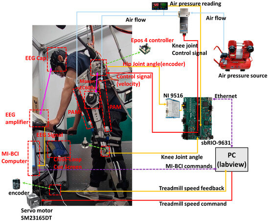
Figure 2.
LLRER and treadmill gait system architecture (The red line is the command from the controller and the yellow line is the feedback signal).
The list of equipment used is shown in Table 1, the knee joint is controlled by a proportional directional valve (MPYE-5-M5-010-b) with a control voltage of 0 V to 10 V, and the knee joint adopts antagonistic actuation as shown in Figure 2. Two PAMs apply force in each direction, and the angle of rotation of knee joint is controlled by the force applied by the two PAMs. Compared with the single-sided PAM system in which the return force comes from gravity or springs, this control method can obtain greater joint torsional rigidity, and thus achieve more accurate tracking control. In Figure 2, the knee joint control architecture consists of directional valve to control the air flow direction from the air pressure source, and a single directional valve to control a single joint, and the feedback data are the air pressure and joint angle values.

Table 1.
Specification list of hardware and equipment for the proposed LLRER.
The control structure of the hip joint is in the middle section of Figure 2. The sbRIO outputs an analog potential control signal to the motor controller, which linearly matches the control signal from 10 V to −10 V to the motor speed from 1000 rpm to −1000 rpm, and then connects the encoder signal from the EC60flat motor through the NI9516 module back to the sbRIO to do the position feedback. The treadmill is controlled by USB-to-RS232 communication from the PC.
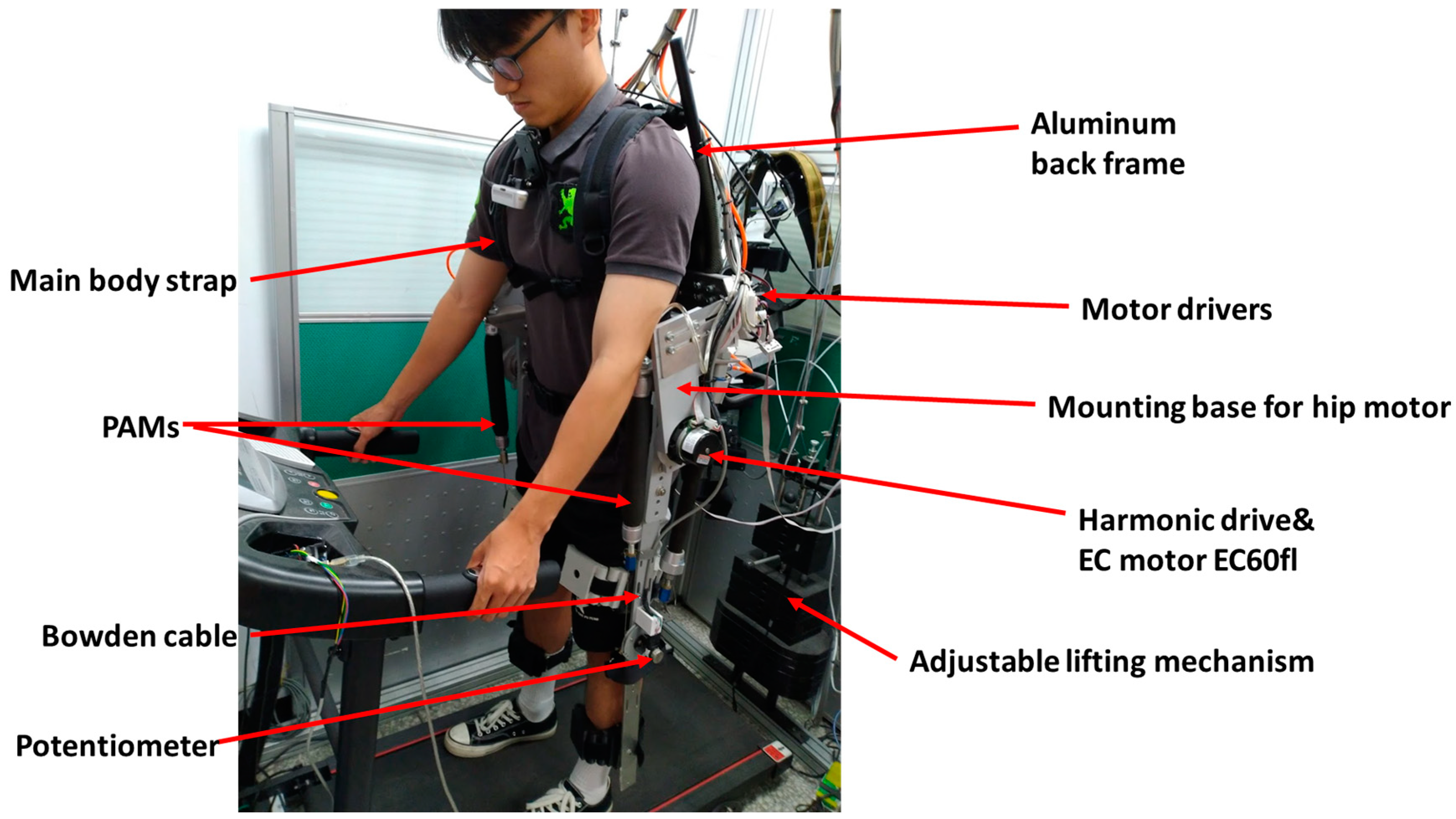
Figure 3 shows the mechanism and function of the exoskeleton. The aluminum alloy back frame lifts the LLRER by passive weights, the hips are driven directly by a 100:1 reducer, the knees are pulled by bowden cables, and the LLRER is secured to the participant by a straps and a waist belt. LLRER has a total of 4-DOF (Degrees of Freedom), two hip and two knee joints, and the controller’s gait tracking is accomplished by using left and right gait mirroring (a difference of 0.5 gait cycles). Gait position tracking was adopted for all four joints. The main reason for neglecting the ankle joint is that applying large torques to the foot without the use of a fit-to-size foot-interface can be painful [28].
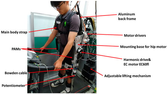
Figure 3.
Exoskeleton function and mechanism description.
The overall LLRER is controlled by external MI-BCI commands and receives startup commands and returns the current LLRER status via TCP/IP communication. When the LLRER is triggered, the treadmill will be activated and the whole LLRER will perform a complete gait motion tracking and return to the standing position to wait for the next trigger command.
2.2. BCI Integrated with Virtual Reality (VR) and Channel Quality Acquisition
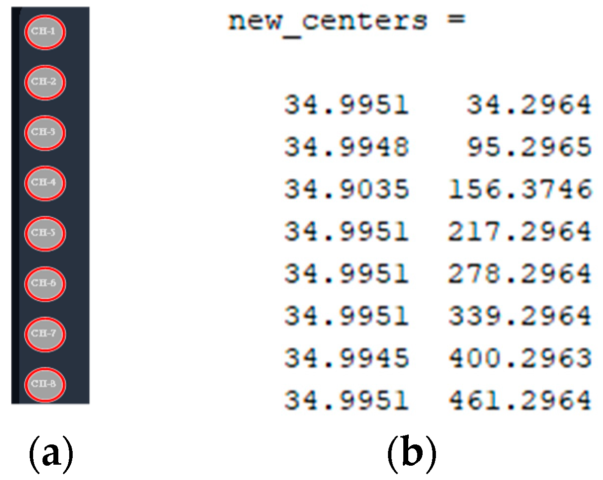
In order to obtain a more complete record of the data for more detailed analysis, an image processing acquisition process was also added, as shown in Figure 4, for real-time recording of the channel quality. First, before the experiment, we first took a screenshot of the screen and set the region of interest (ROI) for the circle search, and then we used the Hough’s Conversion to search for the circle. The 8 regions of the channel quality are identified automatically as shown in Figure 5a, and the center of the circle is located in Figure 5b.

Figure 4.
Channel quality acquisition flowchart.
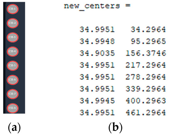
Figure 5.
Hough Circles finds pixel coordinates for channel quality. (a) Screenshot of circle findings; (b) calculated center coordinates.
Then, while the experiment was in progress, the data collection program would identify and classify the RGB colors near the center of the circle and record the channel quality, which was divided into five categories as shown in Figure 6. The RGB values corresponding to the five categories are shown in Equation (1), with very poor (1 point) and good (5 points).

Figure 6.
Signal quality level of BCI software interface (HippoScreen Neurotech).
Class recognition formula is shown in Equation (2). Take the captured RGB values and the stored values from CQ1 to CQ5 as vectors and calculate the angle between the RGB value vector and the stored color vector, with the threshold set to 5 degrees; if the captured RGB calculation angle is less than 5 degrees, then it will be determined to be the corresponding class. This calculation was fast and simple, and was suitable for data acquisition in the background while the MI-BCI was occupied with a large amount of computing resources.
2.3. Virtual Reality (VR) and MI-BCI System Integration
The advantage of VR is its ability to provide a first-person experience of the environment. Pre-recorded footage of the first-person LLRER walking was required. In the experimental session, first-person footage was rendered in VR for the participant to observe, in an attempt to enhance the sense of immersion and to obtain the most accurate BCI model.
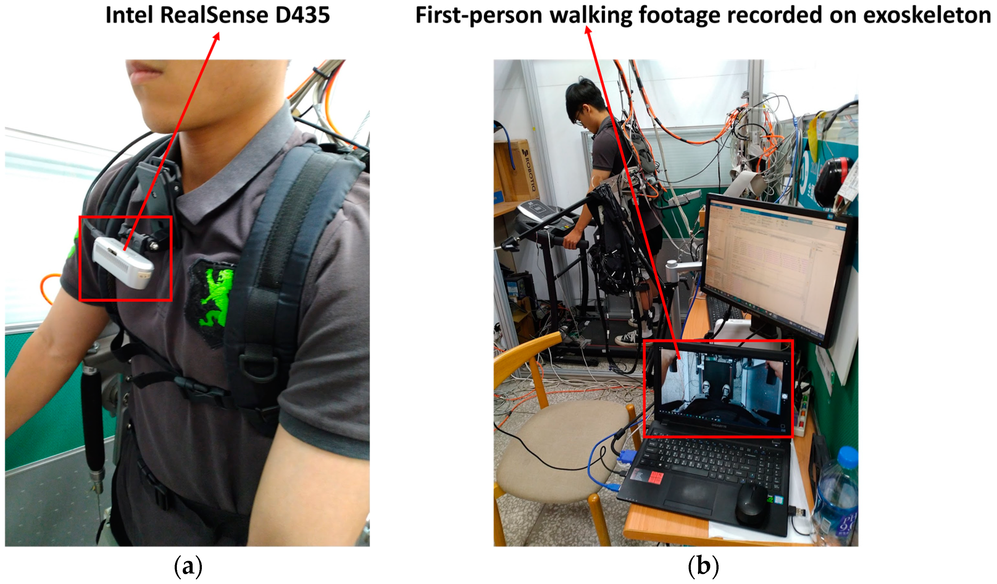
The first-person exoskeleton walking video was recorded as shown in Figure 7. First, the D435 camera (Intel, Santa Clara, CA, USA) was clamped onto the subject’s collar, and the subject’s feet were captured in a downward direction as shown in Figure 7a. The recorded first-person perspective shown in Figure 7b. The screen occupancy ratio was such that the subject’s feet were in the center of the screen, the upper 1/3 of the screen was the treadmill belt, and the lower 1/3 of the screen was the subject’s legs with a portion of the exoskeleton in the lower extremities.
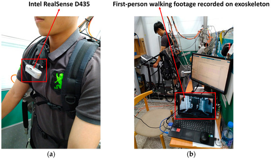
Figure 7.
First-person exoskeleton walking footage recording scene. (a) D435 setup location; (b) recording environment.
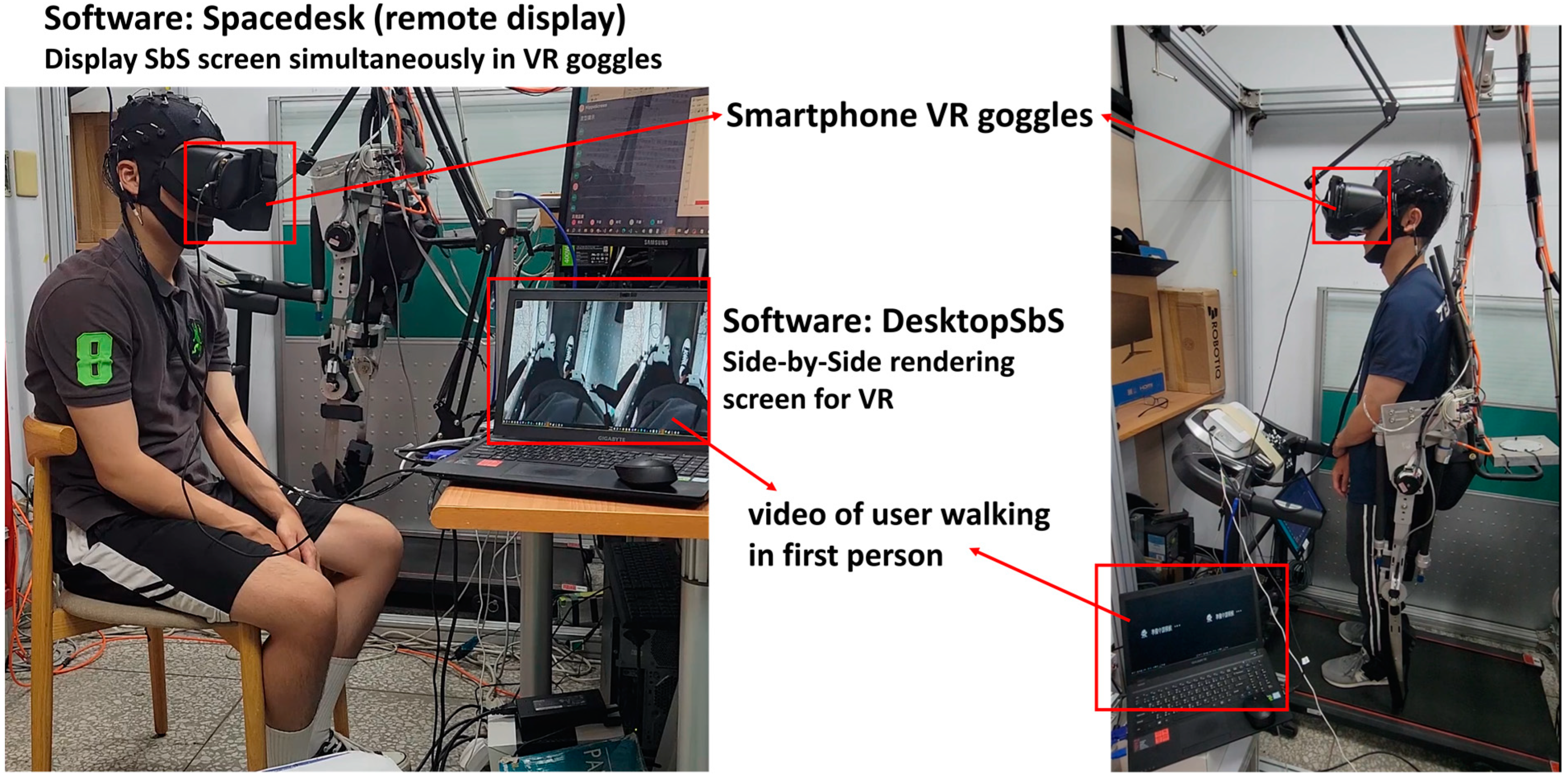
The overall system was designed to support EEG data collection in both standing and sitting postures, and the two cases are shown in Figure 8. For the VR glasses, a ZenFone Max-Pro cell phone (ASUS, Taipei, Taiwan) was used as the display screen for the VR glasses. The VR screen was cut into the binocular vision of VR by using DesktopSbS (v1.3.) software application [29], as shown in the middle part of Figure 8, and then used Spacedesk software (DisplayFusion 11.0) application [30] to stream the screen to the VR glasses via USB. In the data collection stage, the user can watch the pre-recorded first-person rehabilitation scene directly through VR.
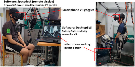
Figure 8.
VR and BCI system integration and setup (sitting/standing).
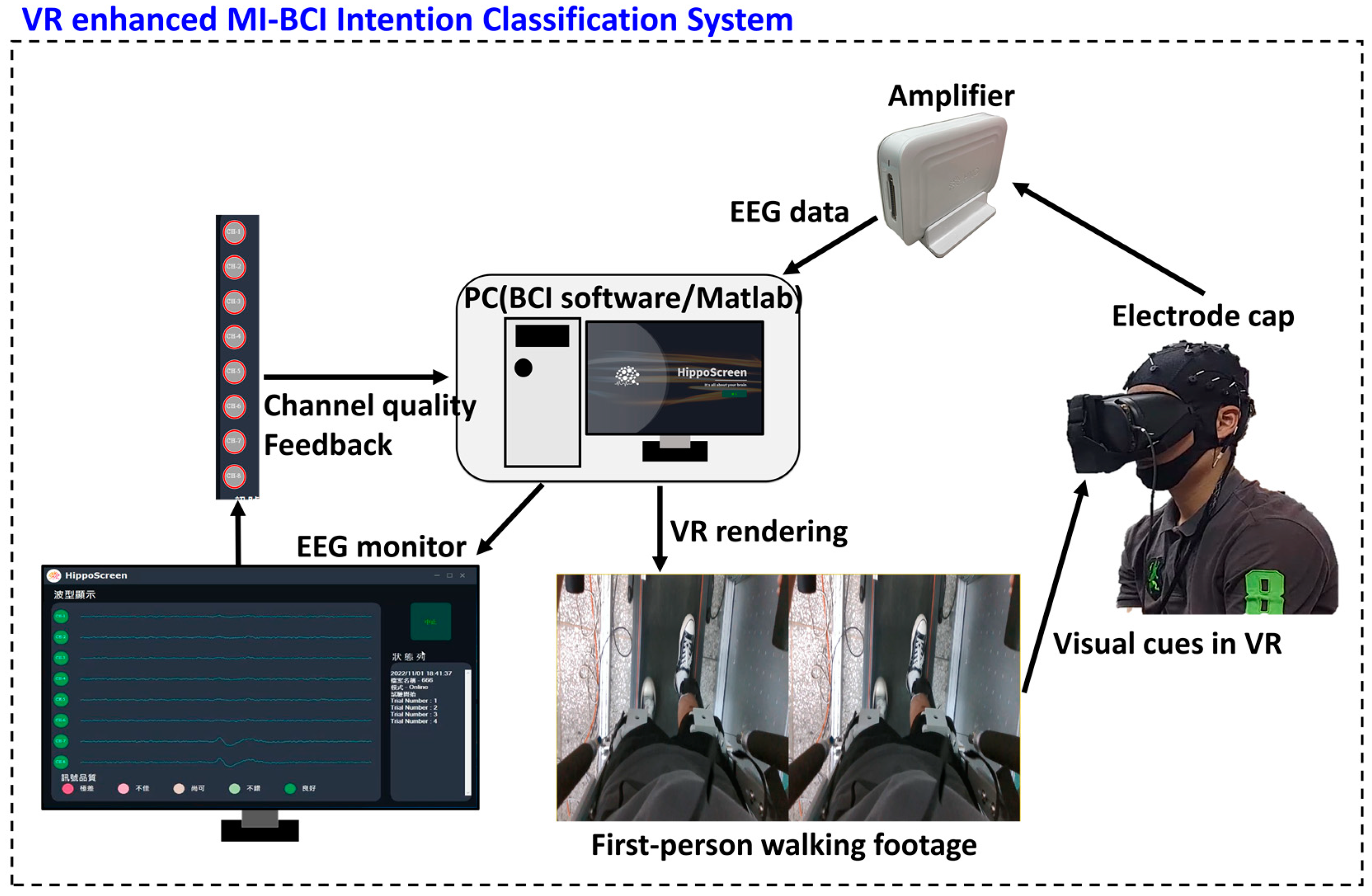
The overall architecture of the MI-BCI classification system enhanced by VR is shown in Figure 9. Expanding on the original BCI architecture, we added signal quality feedback (essential for online BCI rehabilitation integration) and VR binocular visual rendering. We integrated the VR-BCI system into a program capable of simultaneously collecting EEG data, VR visual cueing, and EEG signal quality feedback. The development environment of the program was matlab2022a. Brainwave signals were captured using an eight-channel EEG amplifier (EAmp-0001, HippoScreen Neurotech, Taipei, Taiwan). The device specifications are listed in Table 2.
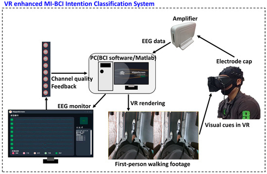
Figure 9.
VR and BCI system integration architecture.

Table 2.
EEG equipment specifications.
VR binocular visual rendering provides a way to split the screen into display modes that can be displayed by VR glasses, and was used for the data collection case of Figure 8’s model training (with VR) (including sitting and standing poses). VR binocular visual rendering was not used for cue screen and normal screen. The signal quality feedback was only used in the open-loop and close-loop experiments, and was recorded along with the state of the entire system, only to observe the effect of the exoskeleton on the signal quality when the subject was being driven by the exoskeleton.
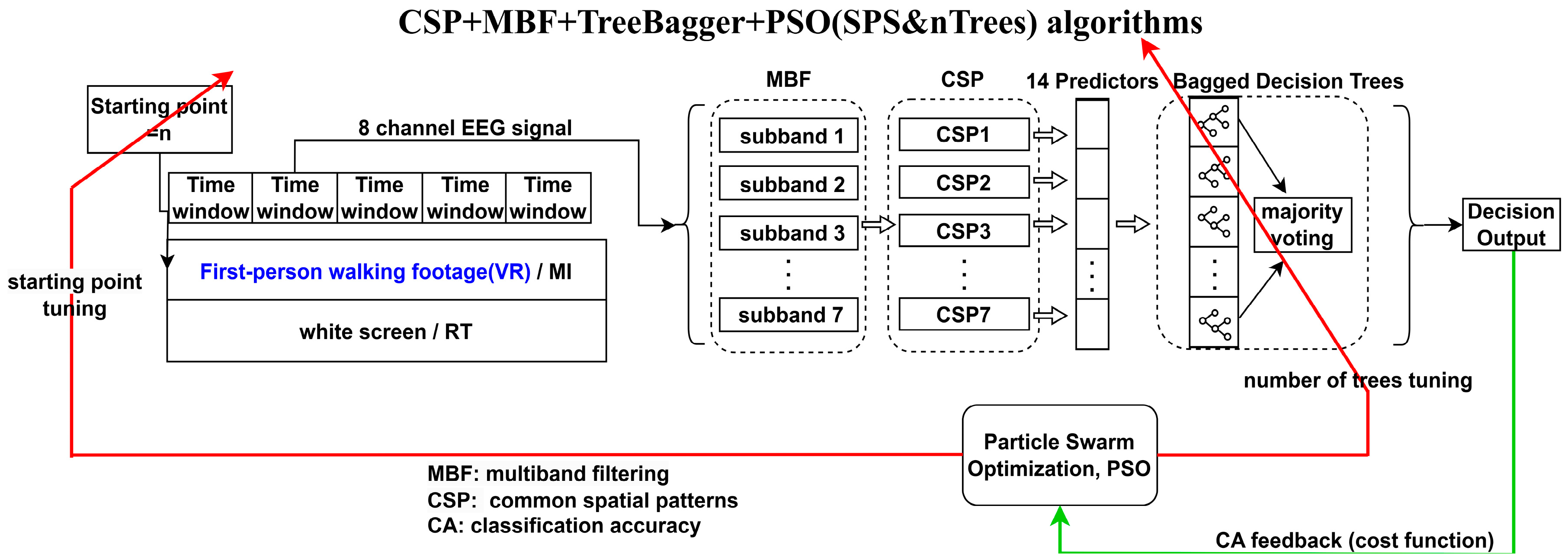
In the experiment of practical application of VR-enhanced model, the fast training optimization architecture CSP + MBF + TreeBagger + PSO (SPS&nTrees) algorithms developed in previous research [26] was used. Specifically a bagged decision tree classifier using common spatial patterns (CSP) with multiband filtering (MBF) and particle swarm optimization (PSO) techniques, as shown in Figure 10. The EEG was divided into sub-bands by MBF, spatial features were extracted by CSP, and then the features were classified by decision tree. PSO was used to optimize the sampling starting point (SP) and other parameters. Previous studies have shown that the CSP + MBF + TreeBagger + PSO (SPS&nTrees) algorithms has fast training and high accuracy. The training time of 83.3 s is suitable for the application.
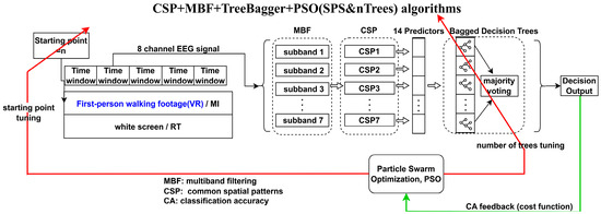
Figure 10.
VR-enhanced MI-BCI classifier training process.
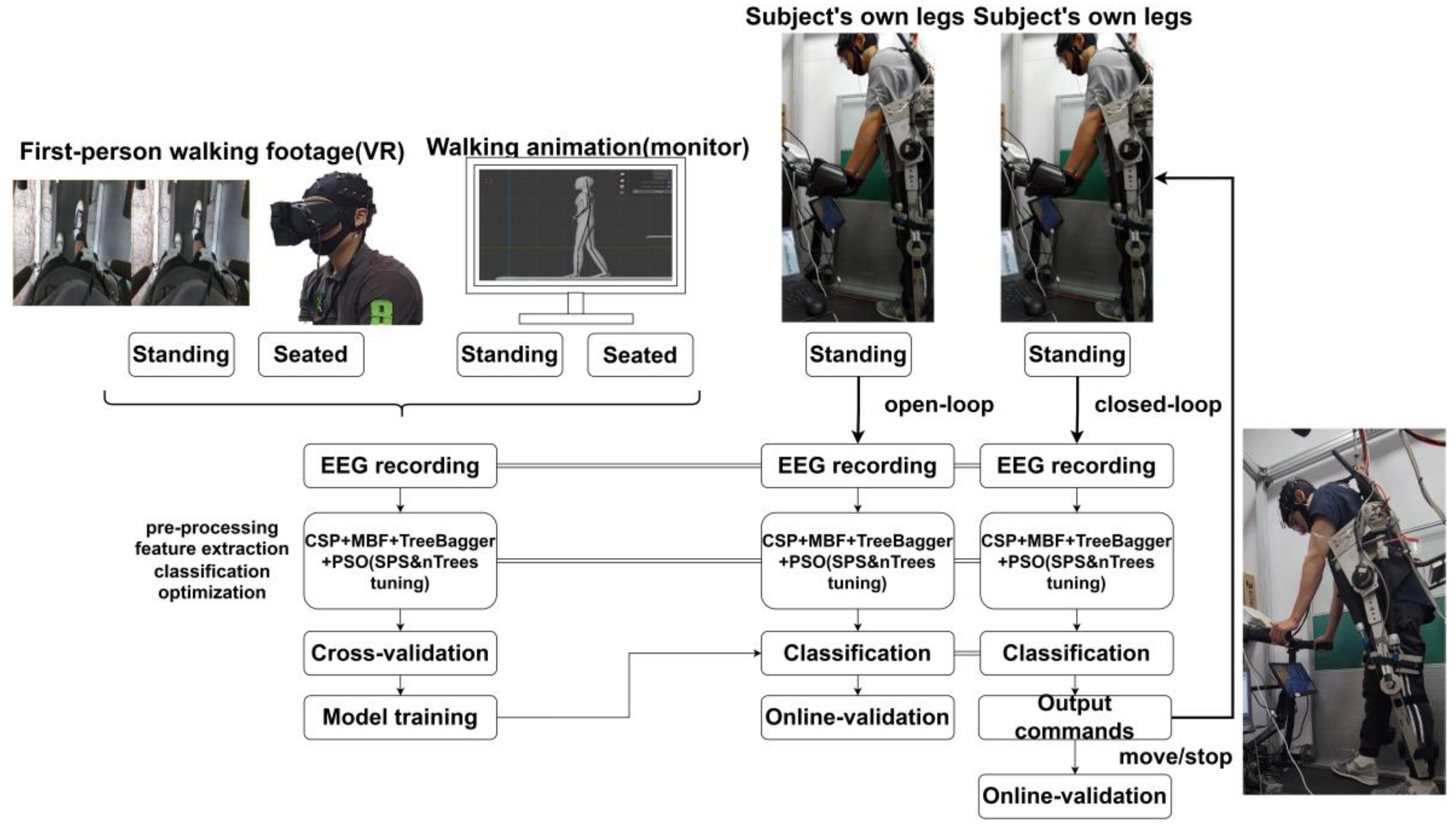
With the different data collection conditions in Figure 15, the EEGs captured for model optimization in Figure 10 come from different perspective conditions of the participants, and VR binocular visual rendering was only used for the model training scenarios that utilized VR. The effect on the overall classification was only to change the test conditions of the source EEG.
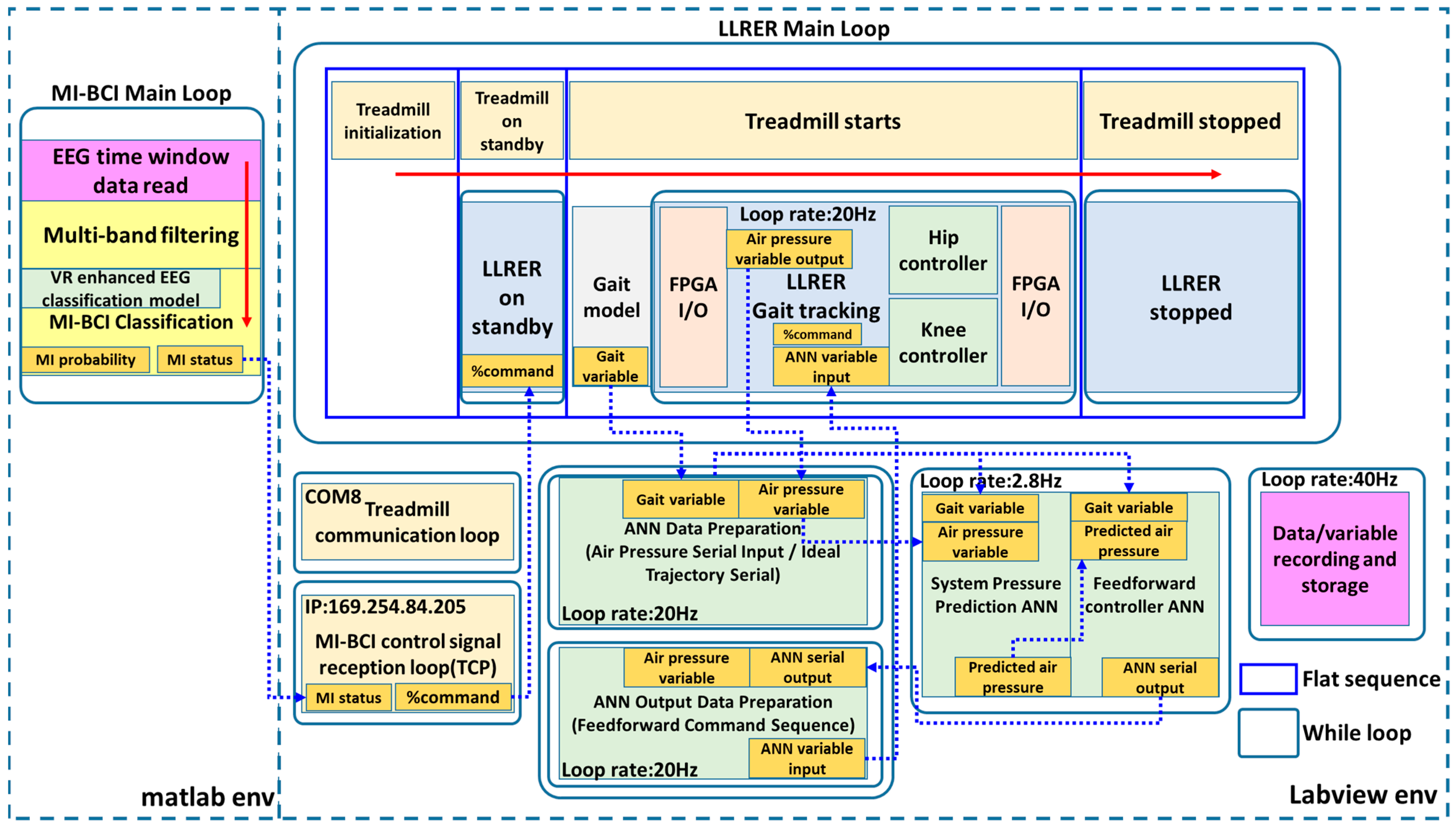
The software architecture diagram of the entire MI-BCI closed-loop LLRER rehabilitation system is shown in Figure 11. The development environment can be divided into two parts: labview and matlab. Orange is the important variables, blue dotted arrows indicate the order of variable transmission, yellow represents the BCI algorithm-related blocks, green is the controller-related blocks, the communication and treadmill function blocks are of the same color, pink is the data reading and storage function blocks, and red arrows are the sequence of program execution.
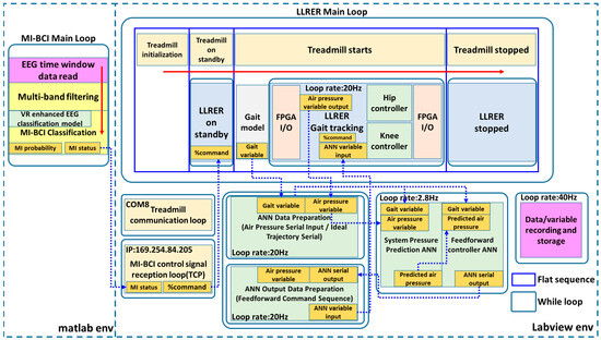
Figure 11.
MI-BCI closed-loop LLRER software architecture.
The matlab part is the main loop of MI-BCI, which is an independent computer responsible for reading EEG signals in real time and processing them in multiple subchannels, and then classifying them with the EEG classification model collected and trained by VR (Figure 10). The MI-BCI Classification block outputs the MI probability of the current EEG window being MI, and if the MI probability exceeds the threshold, it outputs the MI status (MI is 1, RT is 0) to the LLRER control loop. When two of the three consecutive MI statuses are 1, the variable %command becomes 1 to trigger the LLRER recovery action, including treadmill movements and LLRER gait tracking. At the end of the recovery operation (one full gait cycle) the treadmill stops and the LLRER returns to a standing position, waiting for the next trigger.
3. Electrode Selection Experiment for High Focused Gait Mental Task
The experimental design of Mario Ortiz et al. [24] was consistent with the objectives we wanted to evaluate. Since our EEG acquisition device has only 8 channels, the MI-BCI algorithm developed in the previous study was applied in this dataset. Specifically CNN-LSTM + PSO (SPS&neurons tuning) [26] and CSP + MBF + TreeBagger + PSO (SPS and nTrees) algorithms [26].
With this dataset test, we can understand in advance which 8 electrode positions are the most suitable for the following experiments of actually wearing LLRERs online, and further verify whether the MI-BCI algorithm developed in the previous research works well when applied to the actual rehabilitation scenario (where subjects are not in static state).
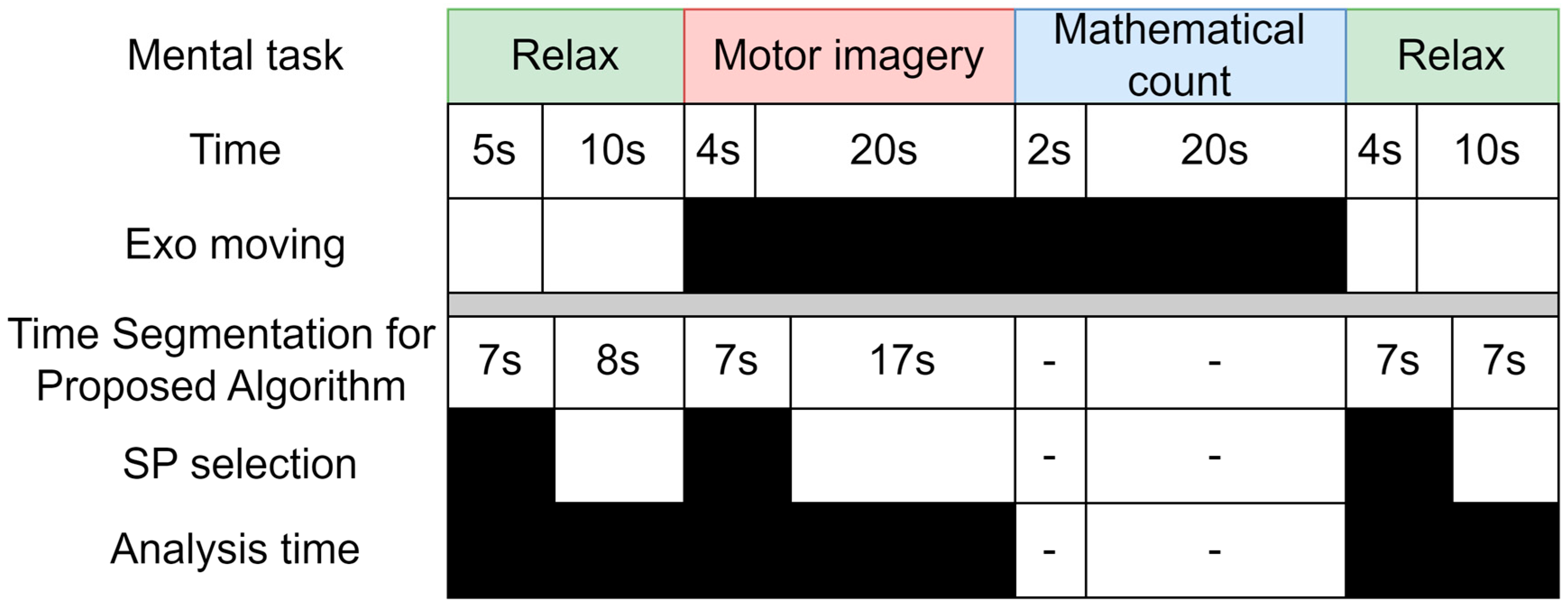
Figure 12 shows the timeline of a single trial from the public dataset provided by Mario Ortiz et al. [24]. The data are provided in two separate datasets on the figshare platform [31]. We utilized the Experience scenario for our analysis. The top half of the figure shows the original analysis time stamps from the public dataset, and the bottom half shows the time stamps we used for our algorithm. Referring to the original approach [24] of ignoring the first 5 s of a phase, here, the search interval of SP (Starting point) was set to 5 s plus 2 s. The data used for the whole dynamic optimized BCI classification model are shown in the analysis time. Includes SP search region and subsequent data region. The EEG data from Relax and MI are used for dynamic search and model training and validation.
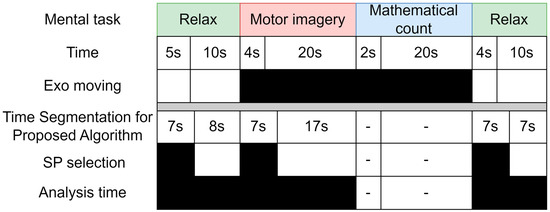
Figure 12.
Timeframe of the publicly available dataset.
In the data selection part, the whole dataset consists of nine subjects, each subject contains 16 trials, the sampling frequency was 200 Hz, and the data were extracted according to the different combinations of electrodes selected. The Relax phase was divided into two stages, 15 s and 14 s long, respectively. The 15 s long Relax phase had eight electrodes, 200 samples per second, 16 trials per person, and the data were a matrix size of 8 × 3000 × 16. The data matrix size of the 14 s long Relax section was 8 × 2800 × 16. The matrix size of the MI segment was 8 × 4800 × 16.
SP searches were performed for each data segment during the PSO tuning stage, and the RT data were combined during the training of the classification model. In the following experiments, 5-fold cross-validation was used.
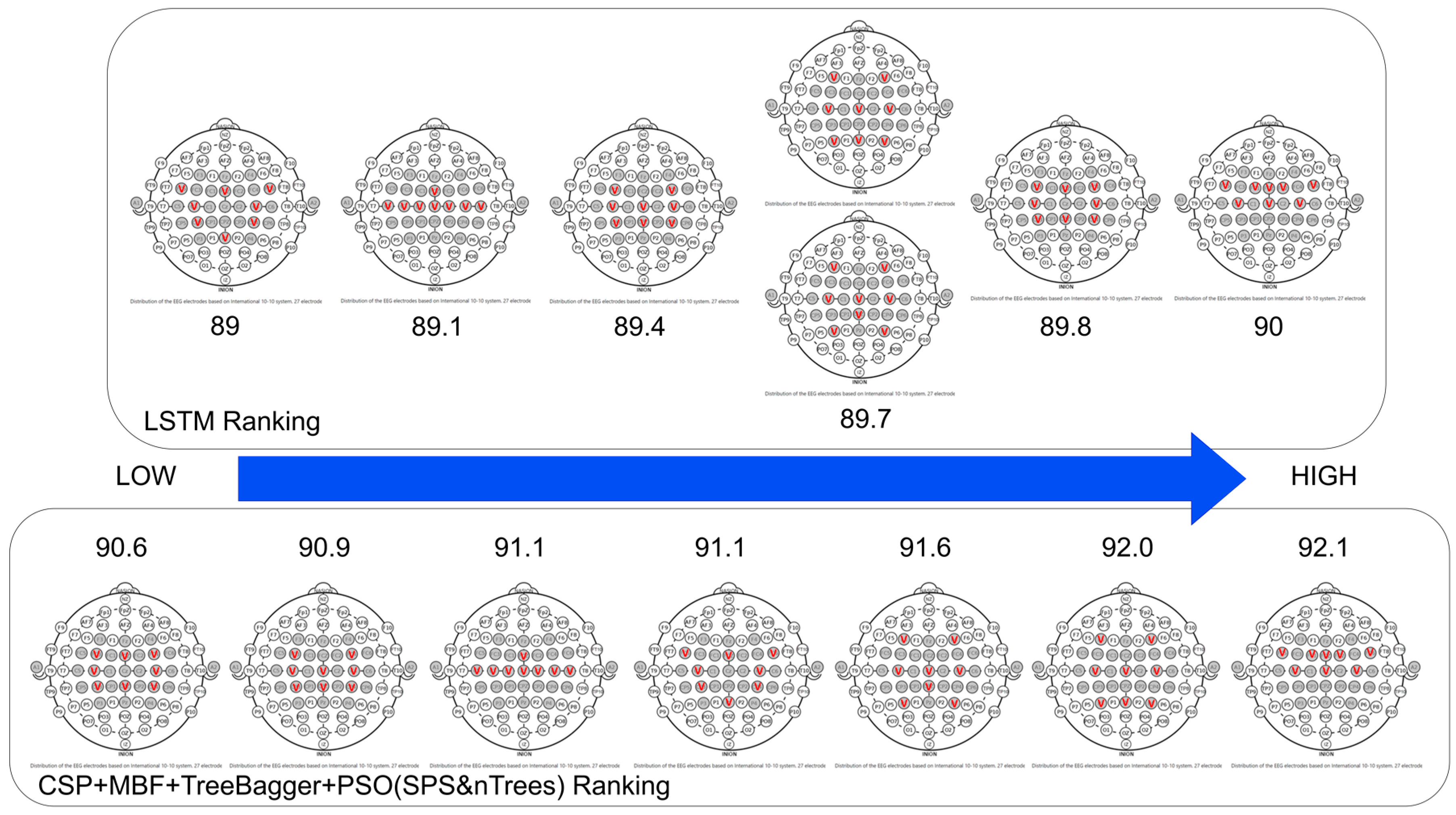
Figure 13 shows the ranking of all electrode choices according to the average classification accuracy of the nine subjects. In the performance ranking of the validation set Va, from left to right, the best performance is on the far right. Both CNN-LSTM + PSO (SPS&neurons tuning) [26] and CSP + MBF + TreeBagger + PSO (SPS and nTrees) algorithms [26] perform best with electrode choice (CZ, C3, C4, FC1, FC2, FC5, FC6, FCZ), and some consistency can be seen in the rankings.
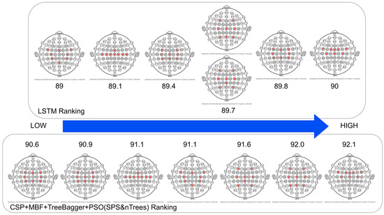
Figure 13.
Ranking of validation sets for different electrode choices.
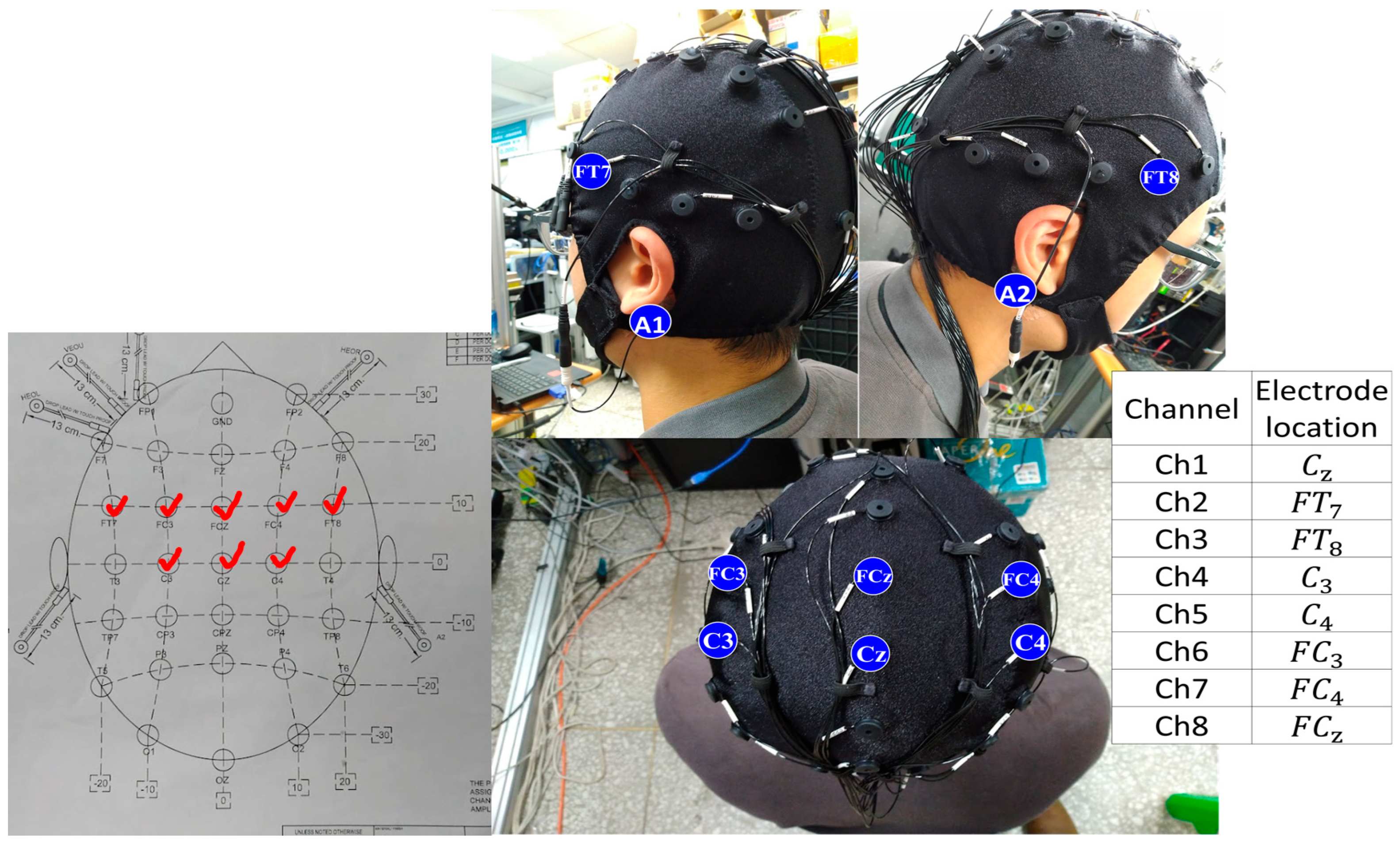
The electrode distribution of the 10–20 system corresponding to electrode choice (CZ, C3, C4, FC1, FC2, FC5, FC6, FCZ) is shown in Figure 14. Due to the limitation of our equipment, the following close-loop experiments were carried out using the electrode choices of the 10–20 system (CZ, FT7, FT8, C3, C4, FC3, FC4, FCZ), where A1 and A2 are reference points.
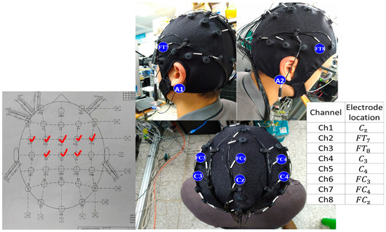
Figure 14.
Electrode selection for 10–20 systems.
4. Closed-Loop Application of VR-Enhanced Gait MI Classification Model in LLRER
4.1. VR-Enhanced BCI, Exploring the Differences in Subjects’ Perspectives
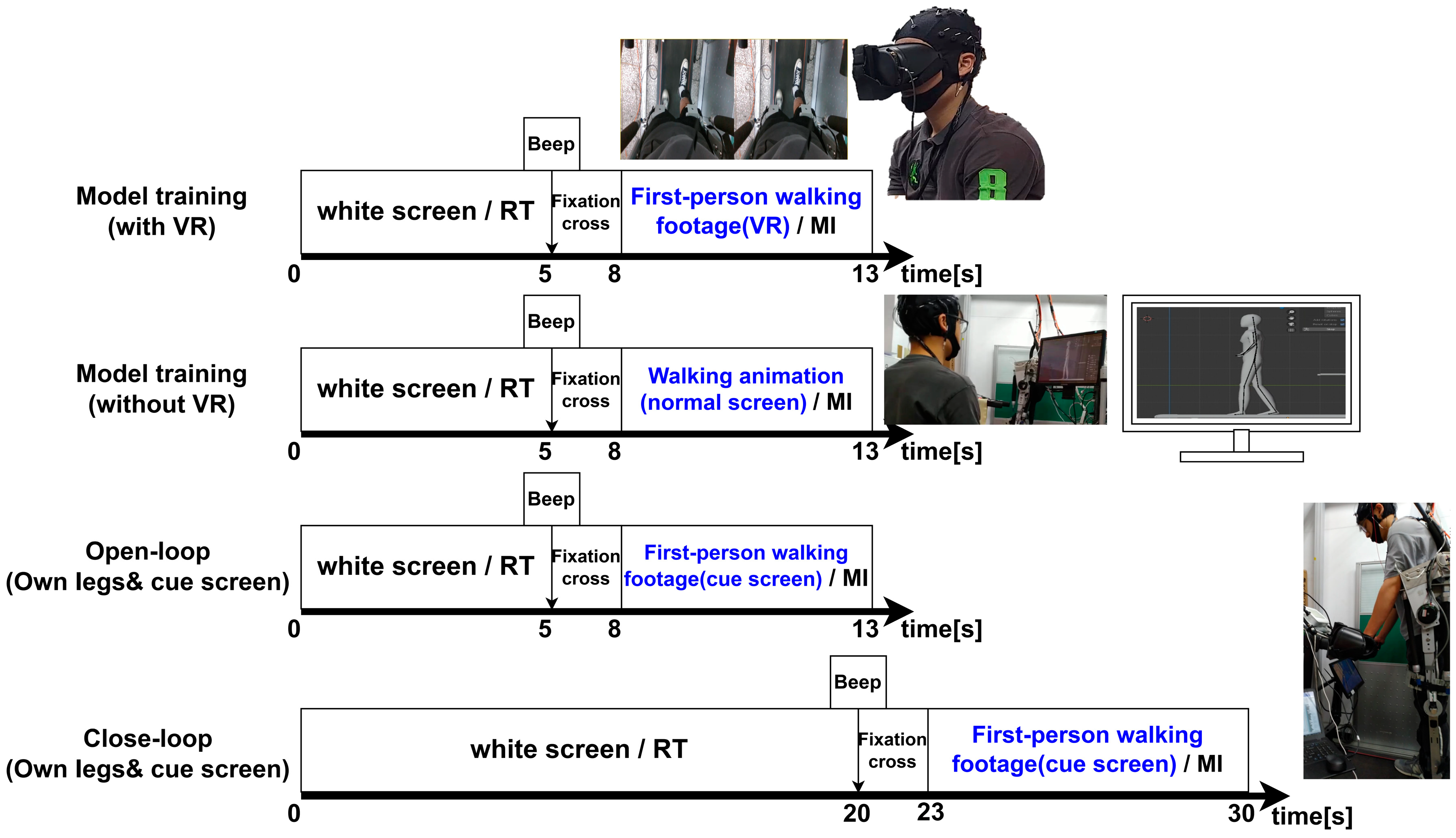
The experiment was designed as shown in Figure 15, in which the EEG data of subjects in sitting/standing, VR/without VR conditions were collected for 30 trials each, and the BCI model was trained. Then, in an open-loop test, participants stood still while wearing the LLRER and followed cues on a small screen at their feet (to label EEG data). While they watched their legs, they performed motor imagery and brain relaxation tasks. The open-loop test lasted for 10 trials, and based on these 10 trials, we observed what adjustments needed to be made to the original model in order for it to be suitable for the closed-loop test (real-life situation). After the model was adapted, the participant was actually allowed to perform the closed-loop rehabilitation training.
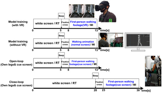
Figure 15.
Single trial timeline for data collection and application.
The single trials for data collection, open-loop and close-loop are shown in Figure 15. In the case with VR, the MI task was performed in the data collection modeling training phase while the participant was wearing VR and watching the first-person walking footage. In the case without VR, the MI task was performed by observing a walking animation on a normal monitor. In both the open-loop and close-loop phases, the participant’s own feet were viewed and followed the small screen prompts.
In our proposed framework, the wearing of VR is only in the data collection stage (Figure 15). In the data collection stage, the test subjects are only in two states, i.e., sitting and standing, so there should not be a major issue of balance when wearing the VR because of the static state of the test subjects. We have considered that the participant can see their own legs, so in the close-loop test, we chose to let the participant not wear VR, and use their own lower limbs as the visual and body perception feedback.
The data collection for model training consisted of 30 trials, with 5 s of RT, 3 s of preparation (black cross), and 5 s of MI in each trial. The open-loop test consisted of 10 trials, with 5 s of RT, 3 s of preparation (black cross), and 5 s of MI in each trial. The closed-loop test consisted of 5 trials, each with 20 s of RT, 3 s of preparation, and 7 s of MI. The reason for the differentiation was that the EEG quality would drop drastically during the actual gait, and after triggering the gait, it required a period of time for the user to calm down and relax, and let the EEG channel quality stabilize before the next MI triggering.
The trigger signal control of LLRER refers to [20], and the control command is called %command. Two of the three continuous time windows categorized as MI will trigger the LLRER to start. The %command was equal to 1 when the LLRER was activated and 0 when the LLRER and the treadmill were stopped.
Figure 16 can be divided into two stages of testing. In the first stage, the EEG classification models of the four cases are tested on the open-loop data to determine which EEG collection method is most suitable for the real-world application scenarios. The second stage is to use the model with the best performance in the open-loop test stage to conduct the full closed-loop test.
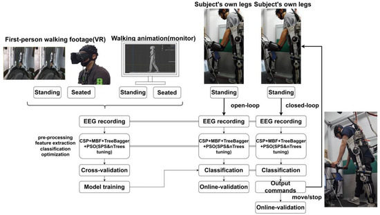
Figure 16.
Experimental design of VR-enhanced gait MI classification model for closed-loop application of LLRER.
The purpose of adding the open-loop test is that the EEG signal in the closed-loop test has a lot of noise when the subject is walking, so it is difficult to calculate the model accuracy through the closed-loop test. The only difference between the open-loop and closed-loop tests is that the LLRER is not actually triggered, so it is possible to record the subject’s brain activity while wearing the LLRER in a complete and undisturbed manner.
4.2. MI Threshold Auto-Leveling Based on CDF
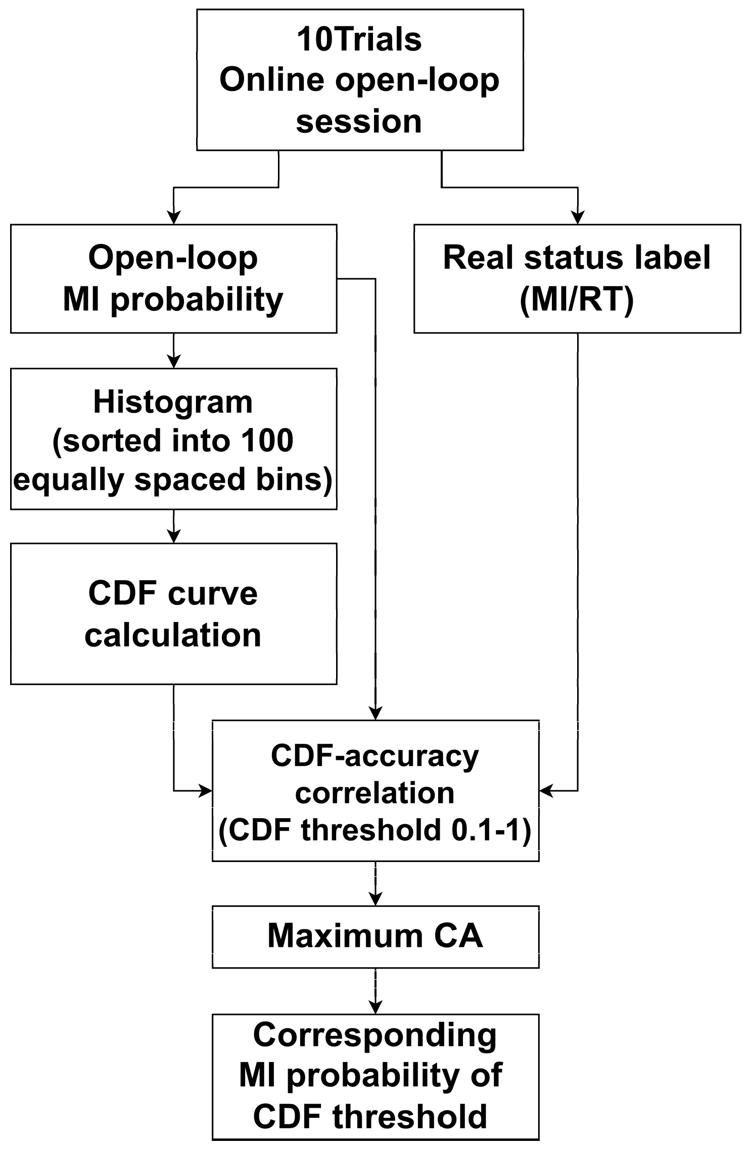
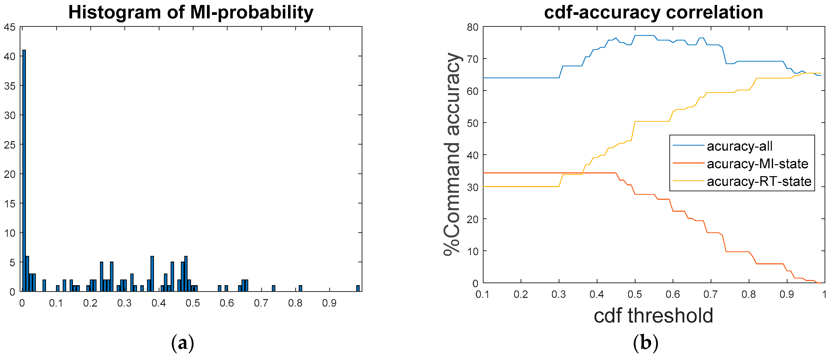
Secondary calibration of the classification model using open-loop test data is the key to making closed-loop tests accurate. Figure 17 automates this process. The original probability of MI with open loops was divided into 100 equal groups from low to high by histogram and counted (Figure 18a). We can calculate the cumulative distribution function (CDF) using the histogram and obtain the CDF curve. By adjusting the selection of the CDF value, the range of variation in MI probabilities for each subjects can be standardized. Then, with the true labeling, we can adjust the sampling points arbitrarily on the CDF curve to obtain the corresponding MI split probability values, so that we can calculate the optimal MI split probability points and apply them to the closed-loop experiments (Figure 18b).
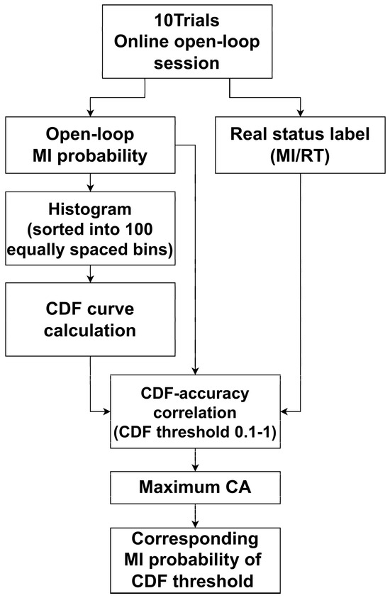
Figure 17.
Automatic cdf baseline correction program flow chart.
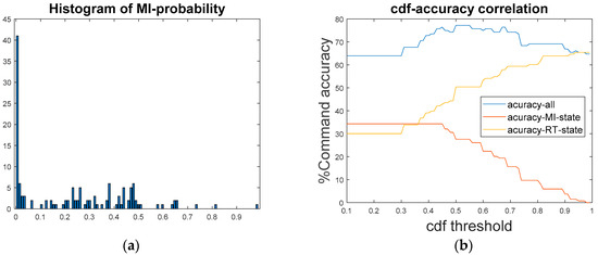
Figure 18.
S4 open-loop data diagram. (a) MI probability distribution histogram, (b) cdf accuracy correlation.
4.3. Open-Loop Experiment of MI-BCI System
The description about the symbols is shown in Table 3. The nVR-SIT represents the MI data collected using first-person VR at a normal walking speed, with the user’s state being seated. Symbol state is the label of the actual mental task of the brain. The %command is the triggering command to be sent to the LLRER after the calculation. The channel quality is the average of the channel quality returned as described in Figure 6. The information of the participants is shown in Table 4. Since closed-loop rehabilitation requires the tracking of the joint model, five healthy participants with a wide range of heights from the shortest 1.64 m to the highest 1.77 m were selected for the experiment.

Table 3.
Status symbol description table.

Table 4.
Information of the participants.
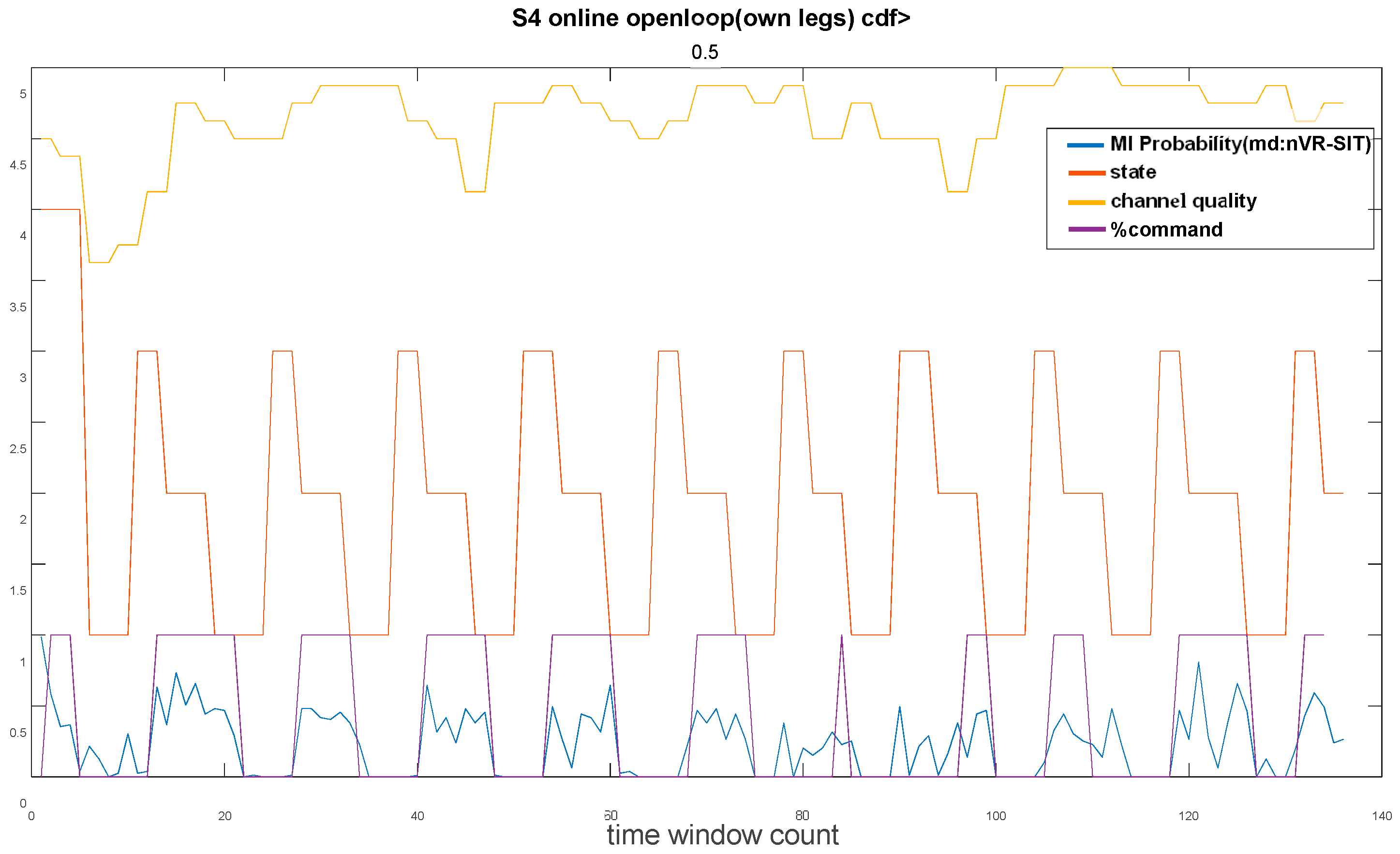
Figure 19 shows the open-loop state diagram of subject S4. From the nVR-SIT probability plots, it can be seen that the MI probability of the subject wearing the LLRER in the standing state only exceeds 0.5 in a small portion of the MI state region. This phenomenon was due to the discrepancy between the state of the subject during the training of the EEG model and the actual state of the subject wearing the LLRER. The LLRER was worn in a standing condition with more environmental disturbances than when the subject was sitting statically.
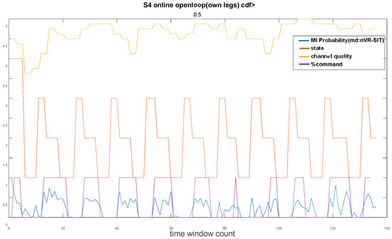
Figure 19.
Open-loop state waveforms (10 trials) for subject S4.
After the CDF search in Figure 18b, the optimal modulation CDF threshold has been found to be 0.5, which corresponds to the MI split probability threshold of 0.232. After applied the new MI classification threshold, we plotted the %command. The state diagram of the optimized search is shown in Figure 19. It can be seen that the %command and state:MI areas are highly overlapped after the adaptation, which means that the CDF search has significant improvement in the open-loop phase.
The results of open-loop testing and CDF calibration for 5 subjects are shown in Table 5, where %CA stands for %command accuracy. The accuracy is calculated by comparing the %command state with the state duration. Since LLRER has only two modes, i.e., gait and stopped, state 3 (ready) is equal to MI and state 4 (exception) is equal to RT. When %command turns to 1, the state must be 2 or 3 to consider the MI state precisely triggered. On the other hand, when %command is 0, the state must be 1 or 4 to consider RT state precisely triggered.

Table 5.
BCI system open-loop experiment.
From the average %CA after calibration, we notice that the best performance in the open-loop test is the nVR-SIT model averaging 75.4% after adjustment, followed by wa-SIT at 74.2%, nVR-STD at 72.4%, and wa-STD at 71.8%, and the ranking result was still that the sitting posture was better than the standing posture.
This result also indirectly reveals that VR can improve the classification accuracy of MI-BCI to a certain extent compared with normal screen. Standing posture is associated with poorer classification performance than sitting posture. This may be due to the fact that the standing posture may affect the classification accuracy because the brain activity of the subject to maintain balance is captured during the EEG recording. Classification accuracy was generally higher in subjects who were sitting in a completely static state.
In the standing data collection phase, balancing activity is equivalent to adding an irregularly evoked lower-limb motor execution (ME) task to the data collection process. Related studies have shown similarities in cortical activation between ME and MI [32].
Our experiment was designed to capture the brain activity features of gait MI, which can be used as an activation trigger for gait rehabilitation, and the exoskeleton will be activated when the participant has a gait movement intention. If the ME features of balancing activity are mixed in the data collection stage, the accuracy of the model in recognizing gait MI might be poor, e.g., the experimental results of Table 5 show that the classification accuracy of standing posture is lower than that of sitting posture on average.
4.4. MI-BCI-Driven LLRER Closed-Loop Experiments
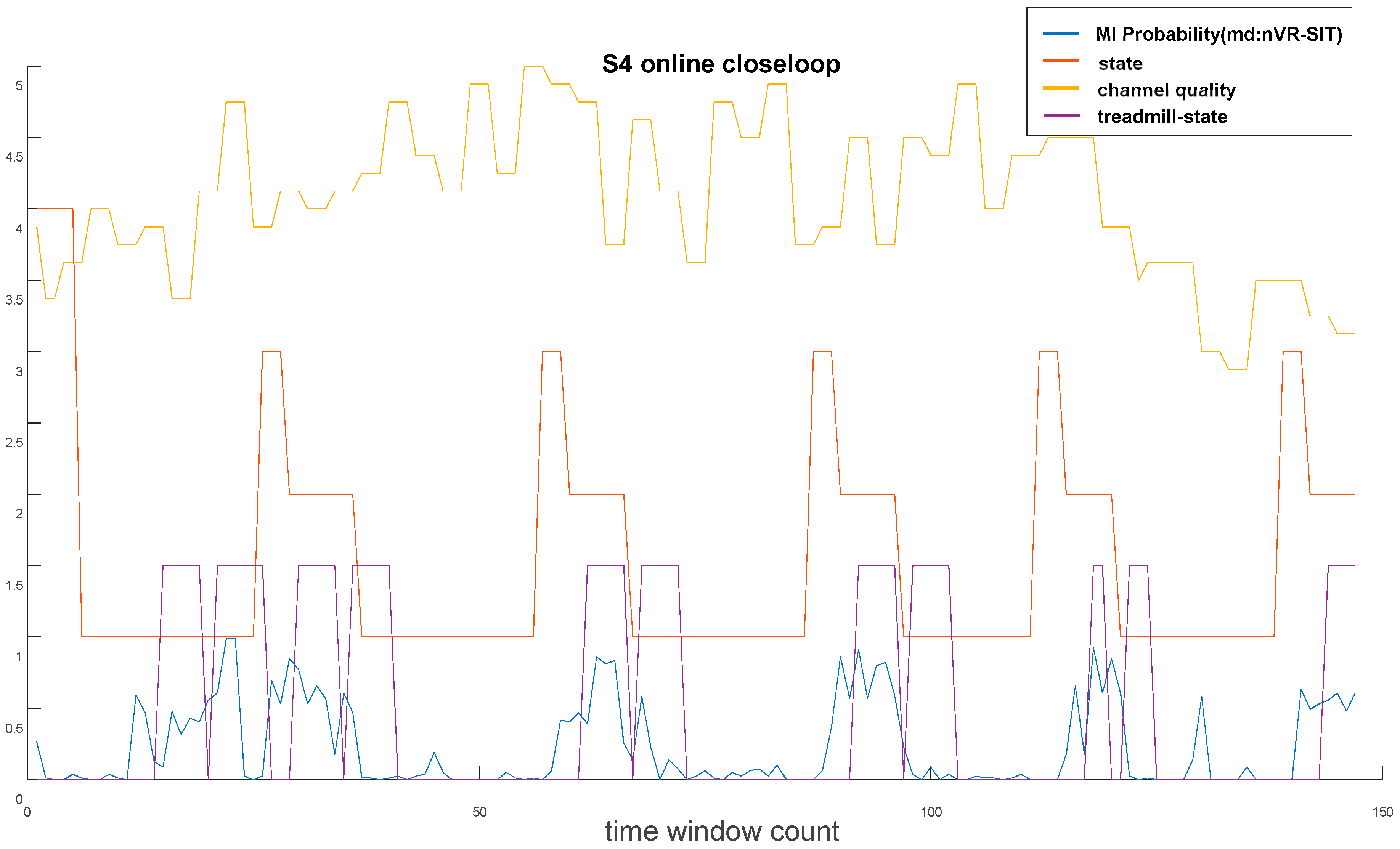
Figure 20 shows the closed-loop status of subject S4. It can be seen that the differences in brain states were vivid. With a classification threshold of 0.232, there was only one false trigger (about 15 s) during the 5 RT periods, and all 5 MI periods triggered correctly. The LLRER actuation within 3 s immediately after the MI period is still counted as the correct MI triggering period, because the %command was referring to the state of the three sequential time windows.
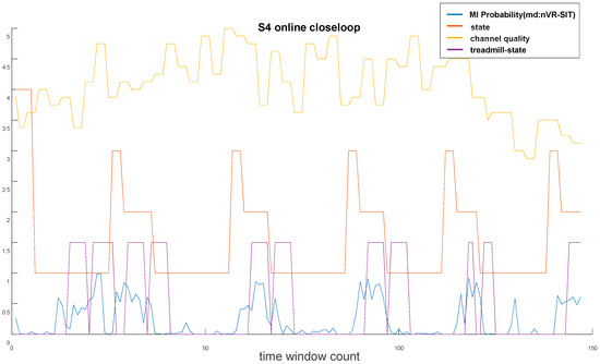
Figure 20.
Closed-loop state waveforms (5 trials) for subject S4.
Table 6 shows the performance of the five subjects in the closed-loop test. After cross-comparison in the open-loop test, it was found that the nVR-sit model performed the best in a situation close to the actual use, so nVR-sit was chosen as the trigger model in the closed-loop test. The electrodes were selected as [CZ,FT7,FT8,C3,C4,FC3,FC4,FCZ]. The EEG signals of the nVR-sit case were collected from 30 trials, and the CSP + MBF + TreeBagger + PSO (SPS&nTrees) model was trained.

Table 6.
BCI system close-loop experiment.
The trained classification model was then used to classify the 10 trials with open loops. The new classification thresholds were then automatically adjusted using CDF auto-leveling. After the adjustment of the new MI threshold, a closed-loop test of 5 trials was conducted based on the new classification threshold to observe the performance of the VR-BCI model when used in a real rehabilitation system.
From left to right, MI_TH is the MI classification probability threshold found by CDF auto-leveling in the open-loop test; RT Triggered represents the number of times the LLRER was in Idle state during 5 RTs; RT False Triggered represents the number of times the LLRER was incorrectly triggered during 5 RTs; MI Triggered represents the number of times the LLRER was correctly triggered during 5 MIs; MI False Triggered represents the number of times the LLRER was in Idle state during 5 MIs; %TA represents the accuracy of LLRER triggering; MI False Triggered represents the number of times the LLRER was in Idle state during 5 MIs; and %TA represents the accuracy of the LLRER’s accurate activation.
The closed-loop experiment has a higher difficulty than static MI experiments. The quality of the data received from the static MI (traditionally defined) test was generally very good and the condition of the subjects was under control.
It is worth noting that the average MI_TH: 0.425 across the 5 subjects shows a general trend towards lower probability, which indicates that the original model has reduced the recognition of the MI category. This decrease in MI recognition was expected considering that the actual wearing of the LLRER has many interfering factors such as standing and balancing in the exoskeleton at the same time, support for potential signals from the arms, and interference from the power supply of the LLRER system itself.
In terms of the accuracy rate of the average RT period, the number of false triggers for the CSP + MBF + TreeBagger + PSO (SPS&nTrees) model was lower in the RT state with an accuracy of four out of five triggers, and the rehabilitation system was generally stationary in the RT state. The average accuracy of MI period was not as high as the RT period, with an average of 3.4 triggers during five triggering periods, and the average %TA was 74%, which was close to the average of 75.35% of the open-loop test after the CDF modification.
5. Discussion and Conclusions
The CDF auto-leveling proposed in this study was still laborious in the adoption process. For example, the real status label in Figure 17 requires the experimental operator to label the time window in real time, which affects the immediacy and convenience of the application to a certain extent.
The use of one classifier type in the experiments was mainly a standardization that must be made in the investigation of point-of-view differences to compare the effects of VR and to observe the differences in the state of the subjects. The differences in MI probability observed in open and closed loops were found when using CSP + MBF + TreeBagger + PSO (SPS&nTrees) as the classifier. If the same calibration framework needs to be applied to other classifiers, more research is needed to observe the differences.
The effectiveness of the CSP + MBF + TreeBagger + PSO (SPS&nTrees) classifier was further validated on a publicly available dataset of the high focused gait mental task [31]. The use of electrode selection methods similar to the publicly available dataset may provide a reference direction for lower-limb gait MI researchers.
For rehabilitation with sensory motor integration, accurate matching between movement intent and sensory feedback is important to facilitate neuroplasticity [33]. When the human body wants to exercise, first, the motor cortex is activated, and then neurotransmission to the muscles leads to lower-limb movements, and during lower-limb movements, there is somatosensory, haptic, visual, and other sensory feedback from the lower limbs. These multisensory feedbacks can induce neuroplasticity, which in turn enhances motor recovery [34].
The system we developed first determines the motor intention by using the MI-BCI classification algorithm on the EEG signals during motor cortex activation. When it is detected that there is a motor intention, the lower-limb exoskeleton is triggered to assist the subject’s limbs to perform gait movement, and the subject will receive various multisensory feedback during the process of being driven, thus completing the closed-loop of rehabilitation. In addition, the addition of VR goggles to provide motion visualization was an attempt to enhance the activities of the motor cortex to improve the performance of the motion imagery.
This endogenous subject intention-driven rehabilitation may apply to patients who have suffered a stroke, hemiplegia, or paraplegia. This rehabilitation is characterized by a top-down approach, initiated by the patient’s own motor intention. Then, through the exoskeleton, the limbs are driven, and the sensory-motor feedback from the limbs reinforces the overall motor control circuitry from the bottom up.
In this study, a VR-enhanced MI-BCI system was successfully implemented using VR goggles and a low-cost software method. We compared the performance of subjects watching a normal screen with that of VR, and the results showed that subjects who watched VR generally had better EEG classification accuracy. The difference in perspectives was compared to the difference in static sitting and standing postures of the subjects. The results show that the model of sitting posture was better and more suitable for direct application to subjects standing while wearing the LLRER.
Through the open-loop CDF calibration, we were able to apply the model trained from the seated VR data directly to the standing subjects wearing the LLRER, and the average %TA reached 74% in the closed-loop test. This result was exciting and represents the preliminary success of our self-developed VR-enhanced MI-BCI-driven LLRER system, which can perform a complete rehabilitation process for different subjects and successfully trigger gait rehabilitation by EEG signals.
Author Contributions
Conceptualization, C.-J.L.; methodology, C.-J.L.; software, T.-Y.S.; validation, C.-J.L. and T.-Y.S.; formal analysis, C.-J.L. and T.-Y.S.; investigation, C.-J.L. and T.-Y.S.; writing—original draft preparation, C.-J.L. and T.-Y.S.; writing—review and editing, T.-Y.S.; visualization, T.-Y.S. and C.-J.L.; supervision, C.-J.L.; project administration, C.-J.L.; funding acquisition, C.-J.L. All authors have read and agreed to the published version of the manuscript.
Funding
This research was funded by National Science Council of the Republic of China, grant numbers Contract Nos. MOST 110-2218-E-027-003, MOST 111-2218-E-027-002, NSTC 112-2218-E-027-007, and NSTC 113-2218-E-027-002. The APC was funded by Contract Nos. NSTC 112-2218-E-027-007, and NSTC 113-2218-E-027-002.
Data Availability Statement
The original contributions presented in the study are included in the article, further inquiries can be directed to the corresponding author.
Conflicts of Interest
The authors declare no conflicts of interest.
References
- Masengo, G.; Zhang, X.; Dong, R.; Alhassan, A.B.; Hamza, K.; Mudaheranwa, E. Lower limb exoskeleton robot and its cooperative control: A review, trends, and challenges for future research. Front. Neurorobot. 2023, 16, 913748. [Google Scholar] [CrossRef] [PubMed]
- Maier, M.; Ballester, B.R.; Verschure, P.F.M.J. Principles of neurorehabilitation after stroke based on motor learning and brain plasticity mechanisms. Front. Syst. Neurosci. 2019, 13, 74. [Google Scholar] [CrossRef] [PubMed]
- Shusharina, N.N.; Bogdanov, E.A.; Petrov, V.A.; Silina, E.V.; Patrushev, M.V. Multifunctional neurodevice for recognition of electrophysiological signals and data transmission in an exoskeleton construction. Biol. Med. 2016, 8, 1. [Google Scholar] [CrossRef]
- Bogdanov, E.A.; Petrov, V.A.; Botman, S.A.; Sapunov, V.V.; Stupin, V.A.; Silina, E.V.; Sinelnikova, T.G.; Patrushev, M.V.; Shusharina, N.N. Development of a neurodevice with a biological feedback for compensating for lost motor functions. Bullet. Russ. State Med. Univ. 2016, 4, 29–35. [Google Scholar] [CrossRef]
- Tortora, S.; Tonin, L.; Chisari, C.; Micera, S.; Menegatti, E.; Artoni, F. Hybrid human-machine interface for gait decoding through bayesian fusion of EEG and EMG classifiers. Front. Neurorobot. 2020, 14, 89. [Google Scholar] [CrossRef] [PubMed]
- Lóopez-Larraz, E.; Birbaumer, N.; Ramos-Murguialday, A. A hybrid EEG-EMG BMI improves the detection of movement intention in cortical stroke patients with complete hand paralysis. In Proceedings of the 2018 40th Annual International Conference of the IEEE Engineering in Medicine and Biology Society (EMBC), 2000–2003, Honolulu, HI, USA, 18–21 July 2018; IEEE: Piscataway, NJ, USA, 2018. [Google Scholar] [CrossRef]
- Leeb, R.; Sagha, H.; Chavarriaga, R. Multimodal fusion of muscle and brain signals for a hybrid-BCI. In Proceedings of the 2010 Annual International Conference of the IEEE Engineering in Medicine and Biology, Buenos Aires, Argentina, 31 August–4 September 2010; IEEE: Piscataway, NJ, USA, 2010; pp. 4343–4346. [Google Scholar] [CrossRef]
- Sargood, F.; Djeha, M.; Guiatni, M.; Ababou, N. WPT-ANN and belief theory based EEG/EMG data fusion for movement identification. Trait. Du Signal 2019, 36, 383–391. [Google Scholar] [CrossRef]
- Leeb, R.; Sagha, H.; Chavarriaga, R.R.; Millán, J. A hybrid brain–computer interface based on the fusion of electroencephalographic and electromyographic activities. J. Neural Eng. 2011, 8, e025011. [Google Scholar] [CrossRef] [PubMed]
- Jimenez-Fabian, R.; Verlinden, O. Review of control algorithms for robotic ankle systems in lower-limb orthoses, prostheses, and exoskeletons. Med. Eng. Phys. 2012, 34, 397–408. [Google Scholar] [CrossRef] [PubMed]
- Macuga, K.L.; Frey, S.H. Neural representations involved in observed, imagined, and imitated actions are dissociable and hierarchically organized. Neuroimage 2012, 59, 2798–2807. [Google Scholar] [CrossRef]
- Eaves, D.L.; Riach, M.; Holmes, P.S.; Wright, D.J. Motor imagery during action observation: A brief review of evidence, theory and future research opportunities. Front. Neurosci. 2016, 10, 514. [Google Scholar] [CrossRef]
- Vogt, S.; Di Rienzo, F.; Collet, C.; Collins, A.; Guillot, A. Multiple roles of motor imagery during action observation. Front. Hum. Neurosci. 2013, 7, 807. [Google Scholar] [CrossRef]
- Taube, W.; Mouthon, M.; Leukel, C.; Hoogewoud, H.-M.; Annoni, J.-M.; Keller, M. Brain activity during observation and motor imagery of different balance tasks: An fMRI study. Cortex 2015, 64, 102–114. [Google Scholar] [CrossRef]
- Berends, H.I.; Wolkorte, R.; Ijzerman, M.J.; van Putten, M.J.A.M. Differential cortical activation during observation and observation-and-imagination. Exp. Brain Res. 2013, 229, 337–345. [Google Scholar] [CrossRef] [PubMed]
- Putze, F.; Vourvopoulos, A.; Lécuyer, A.; Krusienski, D.; Bermúdez i Badia, S.; Mullen, T.; Herff, C. Brain-computer interfaces and augmented/virtual reality. Front. Hum. Neurosci. 2020, 14, 144. [Google Scholar] [CrossRef]
- dos Santos, L.F.; Christ, O.; Mate, K.; Schmidt, H.; Krüger, J.; Dohle, C. Movement visualisation in virtual reality rehabilitation of the lower limb: A systematic review. Biomed. Eng. Online 2016, 15 (Suppl. S3), 144. [Google Scholar] [CrossRef] [PubMed]
- Kohli, V.; Tripathi, U.; Chamola, V.; Rout, B.K.; Kanhere, S. SA review on Virtual Reality and Augmented Reality use-cases of Brain Computer Interface based applications for smart cities. Microprocess. Microsyst. 2022, 88, 104392. [Google Scholar] [CrossRef]
- Mirelman, A.; Maidan, I.; Deutsch, J.E. Virtual reality and motor imagery: Promising tools for assessment and therapy in Parkinson’s disease. Mov. Disord. 2013, 28, 1597–1608. [Google Scholar] [CrossRef] [PubMed]
- Ferrero, L.; Ortiz, M.; Quiles, V.; Ianez, E.; Azorin, J.M. Improving Motor Imagery of Gait on a Brain–Computer Interface by Means of Virtual Reality: A Case of Study. IEEE Access 2021, 9, 49121–49130. [Google Scholar] [CrossRef]
- Lee, K.; Liu, D.; Perroud, L.; Chavarriaga, R.; Millán, J.d.R. A brain-controlled exoskeleton with cascaded event-related desynchronization classifiers. Robot. Auton. Syst. 2017, 90, 15–23. [Google Scholar] [CrossRef]
- Rodríguez-Ugarte, M.; Iáñez, E.; Ortiz, M.; Azorín, J.M. Improving real-time lower limb motor imagery detection using tDCS and an exoskeleton. Front. Neurosci. 2018, 12, 757. [Google Scholar] [CrossRef]
- Quiles, V.; Ferrero, L.; Ianez, E.; Ortiz, M.; Megia, A.; Comino, N.; Gil-Agudo, A.M.; Azorin, J.M. Usability and acceptance of using a lower-limb exoskeleton controlled by a BMI in incomplete spinal cord injury patients: A case study. In Proceedings of the 2020 42nd Annual International Conference of the IEEE Engineering in Medicine & Biology Society (EMBC), Montreal, QC, Canada, 20–24 July 2020; IEEE: Piscataway, NJ, USA, 2020. [Google Scholar]
- Ortiz, M.; de la Ossa, L.; Juan, J.; Iáñez, E.; Torricelli, D.; Tornero, J.; Azorín, J.M. An EEG database for the cognitive assessment of motor imagery during walking with a lower-limb exoskeleton. Sci. Data 2023, 10, 343. [Google Scholar] [CrossRef] [PubMed]
- Ferrero, L.; Ianez, E.; Quiles, V.; Azorin, J.M.; Ortiz, M. Adapting EEG based MI-BMI depending on alertness level for controlling a lower-limb exoskeleton. In Proceedings of the 2022 IEEE International Conference on Metrology for Extended Reality, Artificial Intelligence and Neural Engineering (MetroXRAINE), Rome, Italy, 26–28 October 2022; pp. 399–403. [Google Scholar] [CrossRef]
- Lin, C.; Sie, T. Lower limb rehabilitation exoskeleton using brain–computer interface based on multiband filtering with classifier fusion. Asian J. Control. 2023; online version of record. [Google Scholar] [CrossRef]
- Lin, C.-J.; Sie, T.-Y. Design and experimental characterization of artificial neural network controller for a lower limb robotic exoskeleton. Actuators 2023, 12, 55. [Google Scholar] [CrossRef]
- Veneman, J.F.; Kruidhof, R.; Hekman, E.E.G.; Ekkelenkamp, R.; Van Asseldonk, E.H.F.; van der Kooij, H. Design and evaluation of the LOPES exoskeleton robot for interactive gait rehabilitation. IEEE Trans. Neural Syst. Rehabil. Eng. 2007, 15, 379–386. [Google Scholar] [CrossRef] [PubMed]
- PaysPlat. A Windows 10 Software to Manage 3D Display in Side-by-Side or Top-Bottom Mode. 2024. Available online: https://github.com/PaysPlat/DesktopSbS#readme (accessed on 1 May 2024).
- Space Desk|Multi-Monitor Application 2024. Available online: https://www.spacedesk.net/zh/ (accessed on 1 May 2024).
- Ortiz, M.; de la Ossa, L.; Juan, J.; Iáñez, E.; Torricelli, D.; Tornero, J.; Azorín, J.M. An EEG database for the cognitive assessment of motor imagery during walking with a lower-limb exoskeleton. DECODED: A EUROBENCH subproject. Figshare 2022. [Google Scholar] [CrossRef]
- Meng, H.-J.; Pi, Y.-L.; Liu, K.; Cao, N.; Wang, Y.-Q.; Wu, Y.; Zhang, J. Differences between motor execution and motor imagery of grasping movements in the motor cortical excitatory circuit. PeerJ 2018, 6, e5588. [Google Scholar] [CrossRef] [PubMed]
- Takeuchi, N.; Izumi, S.-I. Rehabilitation with poststroke motor recovery: A review with a focus on neural plasticity. Stroke Res. Treat. 2013, 2013, 128641. [Google Scholar] [CrossRef]
- Li, M.; Xu, G.; Xie, J.; Chen, C. A review: Motor rehabilitation after stroke with control based on human intent. Proc. Inst. Mech. Eng. Part H J. Eng. Med. 2018, 232, 344–360. [Google Scholar] [CrossRef]
Disclaimer/Publisher’s Note: The statements, opinions and data contained in all publications are solely those of the individual author(s) and contributor(s) and not of MDPI and/or the editor(s). MDPI and/or the editor(s) disclaim responsibility for any injury to people or property resulting from any ideas, methods, instructions or products referred to in the content. |
© 2024 by the authors. Licensee MDPI, Basel, Switzerland. This article is an open access article distributed under the terms and conditions of the Creative Commons Attribution (CC BY) license (https://creativecommons.org/licenses/by/4.0/).

