Abstract
To examine the biomechanical demands of manual wheelchair propulsion, it is crucial to determine the wheelchair user’s (WCU) force for propulsion technique parameter calculation. When using a pushrim-activated power-assisted wheelchair (PAPAW) on a wheelchair ergometer, a combined propulsion force from the WCU and PAPAW is exerted. To understand PAPAW’s assistance and distinguish the WCU’s force application from the force exerted by the PAPAW, both propulsion components must be assessed separately. In this study, a calibration of the PAPAW on an ergometer was developed to achieve this separation. The calibration consists of five steps: (I) Collecting data on force and velocity measured from the ergometer, along with electrical current and velocity from the PAPAW. (II) Synchronizing the velocity signals of the wheelchair ergometer and PAPAW using cross-correlation. (III) Calibrating the PAPAW’s electromotors to convert electrical current (mA) to force (N). A product-specific motor constant of 0.30, provided an average ICC of 0.563, indicating a moderate agreement between the raw ergometer data (N) and the motor constant-converted drive-rim (PAPAW) data (from mA to N). (IV) Subtracting the PAPAW’s force signal from the ergometer’s measured force to isolate forces generated by the WCU. (V) Using markerless motion capture to determine and validate the phase of hand contact with the handrim. This technical note provides an example of PAPAW calibration for researchers and clinicians. It emphasizes the importance of integrating this calibration into the development of PAPAW devices to reveal the complex interaction between PAPAW and WCU during wheelchair propulsion.
1. Introduction
To reduce the physical strain associated with manual wheelchair propulsion, various pushrim-activated power-assisted wheels (PAPAWs) have been developed [1]. A PAPAW is essentially a handrim wheelchair equipped with battery-powered electromotors embedded in the wheels, similar to an e-bike. These electromotors generate power in response to the forces applied by the wheelchair user (WCU) on the handrim, providing additional support during the push phase of propulsion and aiming to reduce the biomechanical and physiological demands on the WCU. Manual wheelchair propulsion involves repetitive and physically demanding movements that are closely associated with the development of upper-extremity pain or injuries [2,3,4,5]. By reducing the physical strain through the use of PAPAWs, the musculoskeletal demands on the WCU can be alleviated, potentially decreasing the incidence of upper-extremity pain and injuries.
Optimizing the assistance of a PAPAW is currently a crucial issue to alleviate physiological and biomechanical strain on the WCU while maintaining a certain level of physical activity. Multiple studies have examined the effect of the PAPAW on physiological demands, providing data to optimize the support of the PAPAW in terms of physiological demands [6,7,8,9]. Other studies aimed to optimize the support of PAPAWs based on the environment, such as terrain-type and user intention classification frameworks (e.g., turning or straight-line propulsion) and regenerative braking [10,11,12,13]. Yet, no studies have directly assessed the push of mechanics and mechanical load in the interaction between the PAPAW and the WCU, which is essential to understand how a PAPAW could reduce biomechanical strain on the WCU. This lack of knowledge is due to the difficulty of measuring the biomechanics of propulsion when propelling with a PAPAW.
This difficulty is due to the fact that the extent and manner of support provided by current PAPAWs are not transparent. It is crucial to understand how a PAPAW behaves and how this affects the WCU. It is crucial to gain insights into the behavior of PAPAWs and their effects on the wheelchair user (WCU). Currently, PAPAWs function as black boxes, operating based on pre-programmed algorithms without precise knowledge of the power they provide to assist the WCU. Understanding the amplitude and timing of PAPAW assistance will shed light on its impact on the WCU and offer opportunities to optimize PAPAW performance.
This black box poses a challenge for collecting data on the forces applied by the WCU when using a PAPAW, as PAPAWs usually are not equipped with force sensors. One method to collect force data is to use an existing smart torque or force-measurement wheel during a field test or on a treadmill. However, this is not feasible because the measurement wheel cannot replace the PAPAW. A more specific solution could be to utilize a custom-made PAPAW equipped with specific sensors (e.g., force-calibrated hall effect sensors) to measure the WCU’s force [14]. However, most commercially available PAPAWs are not equipped with these sensors and accompanying software, necessitating an alternative approach.
An alternative solution is to use a wheelchair ergometer equipped with force sensors to measure the tangential forces applied to its rollers. When the handrim is exclusively subjected to user forces or when only the electromotors of the PAPAW are activated, the applied forces correspond with the tangential force measured by the wheelchair ergometer (see Figure 1A,B). However, during PAPAW propulsion, both the WCU and the PAPAW exert combined forces (see Figure 1C). The ergometer does not distinguish between the forces from the WCU and the PAPAW, making it necessary to differentiate these forces to accurately determine the biomechanical demands on the WCU while using a PAPAW.
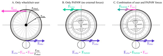
Figure 1.
Forces applied on and measured by a dual-roller wheelchair ergometer. Abbreviations: F, force; PAPAW, pushrim-activated power-assisted wheel; r, radius. The user force is equal to the applied force on the rim (Fhand) multiplied by the ratio between the radius of the rim and the wheel.
To determine the WCU’s applied force from the total force measured by the ergometer, the PAPAW can be calibrated [15,16]. This calibration is necessary since the calibration factors are not available and directly translating the electromotor’s properties to forces does not yield a valid overview of the forces applied by the PAPAW. To open the black box of the PAPAW and gain insight into the individual contributions of the WCU and the PAPAW to propulsion, a calibration method will be developed in the current study. This calibration process will determine the motor constant (к, measured in N/mA) to convert electrical current into force output [17]. By calibrating the PAPAW force, it can be subtracted from the total force measured by the ergometer to accurately determine the WCU’s applied force.
This technical note will give a technologically specific example to serve as a description of how the force applied by a WCU can be distinguished from the force added by a PAPAW, based on the force sensor-equipped wheelchair ergometer and information of electrical current of the PAPAW motor. Five steps are considered. (I) Collecting data with a force sensor-equipped wheelchair ergometer (force and velocity) and PAPAW (electrical current and velocity). (II) The synchronization of ergometer and PAPAW velocity data with cross-correlation. (III) The calibration of the PAPAW’s electrical current (mA) to force (N). (IV) Separating the PAPAW force and WCU force in the ergometer data. (V) Examining if the calculated WCU forces are truly attributable to the WCU using a markerless motion-capture (video) technique to determine hand contact with the handrim. Since this study utilizes specific technical equipment, some additional instrument-dependent steps have been taken. Therefore, the aim of this manuscript is to demonstrate the challenges and solutions for assessing the separate propulsion contribution of user and electrically supported wheelchairs. This procedure will also be relevant for understanding the interaction between users and other commercially available assistive mobility devices such as e-bikes and others.
The current paper will describe the development and results of our assessment technique following the required steps outlined above. In between steps III and IV, an instrument-dependent step was included, which was found to be relevant during the process.
2. Materials and Methods
The PAPAW used in this study is the WheelDrive (Indes Healthcare B.V., Enschede, The Netherlands) (Figure 2). It offers three assistance modes, each defined by the maximum power supplied by the electromotor per wheel during a push: low, medium, and high. The PAPAW supplements power output only when it detects that the WCU is exerting force on the handrim using a predefined proprietary support algorithm based on handrim displacement with respect to the wheel, limited by a spring. Consequently, each push receives varying levels of support. For this study, the supplier facilitated the reading of electrical current (mA) and linear velocity (m/s) of the PAPAW’s electromotors by giving access to corresponding software at 100 Hz. Two PAPAWs were mounted on a Küschall k-series wheelchair (Küschall, Witterswil, Switzerland), with tire pressure consistently maintained at six bar (600 kPa). All the tests were conducted on the dual-roller Esseda wheelchair ergometer (Lode B.V., Groningen, The Netherlands).
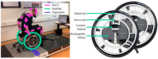
Figure 2.
Measurement set-up with the WheelDrive, which includes a regular handrim for assistive propulsion, drive-rim for fully powered propulsion, control buttons to switch between assistance modes, and a rechargeable battery.
It is important to note that all the example data in the subsequent paragraphs are sourced from a single participant performing 4 blocks of 4 min submaximal propulsion (speed 1.11 m/s and rolling resistance 0.21 W/kg body mass), each block in a different assistance mode (no, low, medium, and high assistance). All the data processing and analyses were conducted using Python 4.2.5 (Python software foundation) using functions from the ‘Worklab: a wheelchair biomechanics mini-package’ [18].
Data were obtained as part of a larger study examining the effect of the level of assistance on biomechanical and physiological demands. Twenty-four able-bodied participants performed 4 blocks of 4 min submaximal propulsion (1.11 m/s and 0.21 W/kg body mass) after a 48 min practice period. A two-minute rest period preceded each block. The participants experienced different power-assist modes (none, low, medium, and high) in a counterbalanced order for each block. Only the data from the last minute of these four blocks were used for analysis. The study received approval from the ethical committee at the University Medical Center Groningen (Groningen, The Netherlands, reference number: 202100883). All the participants signed informed consent.
3. Data Collection and Analysis
3.1. Step I: Collecting Wheelchair Ergometer and PAPAW Data
The Esseda wheelchair ergometer continuously collects tangential force and velocity data from the two rollers beneath each wheel at 100 Hz. Figure 3A provides a small sample of pushes for each mode of assistance of the PAPAW. The ergometer measures forces on the rollers (i.e., only WCU or combined WCU and PAPAW forces) and, based on this input, algorithms determine the resulting roller velocity based on Newton’s law of inertia and predetermined rolling resistance mimicking overground propulsion. As shown in Figure 3A, during no assistance, the force measured by the ergometer is shorter but higher compared to all three assistive conditions. This causes a more rapid acceleration for a shorter period. In contrast, for the low-, medium-, and high-assistance modes, the acceleration is lower, yet, spread over a longer period, resulting in a similar end velocity.
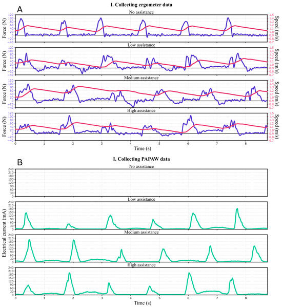
Figure 3.
(A) Raw force and velocity data measured by the wheelchair ergometer. From top to bottom: no, low, medium, and high assistance. Blue is measured tangential force, red is propulsion speed. (B) Raw electrical current (mA) read from the PAPAW’s controlling system during low, medium, and high assistance.
Simultaneous to data collection with the ergometer, data on the electrical current (mA) to the electromotor of the WheelDrive (PAPAW) and its linear velocity (m/s) were obtained at a rate of 100 Hz. During the no-assistance mode, the PAPAW was turned off.
The electrical current values for low, medium, and high assistance are depicted in Figure 3B. A more forceful push by the user results in a higher amplitude of the electrical current generated during that push. When the force input of the WCU exceeds a certain threshold (i.e., lower threshold for higher assistive modes), the roll-out function in this type of PAPAW is activated. The roll-out function serves as an active contribution of the electromotor during the recovery phase, occurring when there is no hand contact with the handrim. The amplitude of the roll-out function is determined based on the amplitude of the preceding push. However, even for vigorous pushes, the amplitude of the roll-out function remains relatively small. This is by design, as its purpose is to gently assist progression during the recovery phase without being overly noticeable to the WCU. In Figure 3B, push-assistance is identifiable by high, steep peaks of electrical current during force application of the WCU. Here also the light activation of the PAPAW can be seen between the steep peaks as a result of the roll-out function, occurring during the recovery phase of the WCU.
3.2. Step II: Time Synchronization for the Ergometer and PAPAW Signals
As the wheelchair ergometer and the PAPAW data acquisition boards could not be synchronized, the PAPAW and ergometer data underwent offline time synchronization. Both the PAPAW and ergometer velocity data were filtered using a 7th polynomial order Savitzky/Golay filter before synchronization using cross-correlation. Figure 4 displays unfiltered velocity data from the high assistance condition for both the ergometer and PAPAW after time synchronization, providing a visual representation of the result of the cross-correlation process.
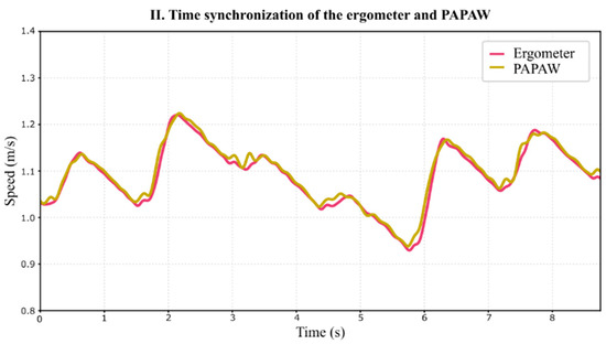
Figure 4.
Raw velocity data from the ergometer and PAPAW after cross-correlation during high assistance.
3.3. Step III: PAPAW Motor Constant Calculation
To determine the electromotor’s force contribution, the electrical current should be scaled by the motor constant [17]. The motor constant, denoted as к (N/mA), was determined using data from two tests (i.e., roll-out function test and drive-rim test), where к represents the ratio between motor torque and input current [16]. For the first test the data, as described in Section 2, was used.
In the initial test, the recovery phase was utilized to convert electrical current into force delivered by the PAPAW. During the roll-out phase, no external forces (i.e., no WCU applied forces) acted on the ergometer, thereby isolating the force applied by the PAPAW’s roll-out function. The ratio (к) between the electrical current of all the roll-out functions of both wheels of all the participants across all three assistive modes and the measured forces recorded by the ergometer was calculated. For a visual representation of this scaling, refer to Figure 5. The determined к for all these roll-outs was 0.30 N/mA (95% CI: 0.29–0.31) and did not differ over all the different assistance modes, which was subsequently used to scale all the electrical current data to derive tangential force exerted by the PAPAW.
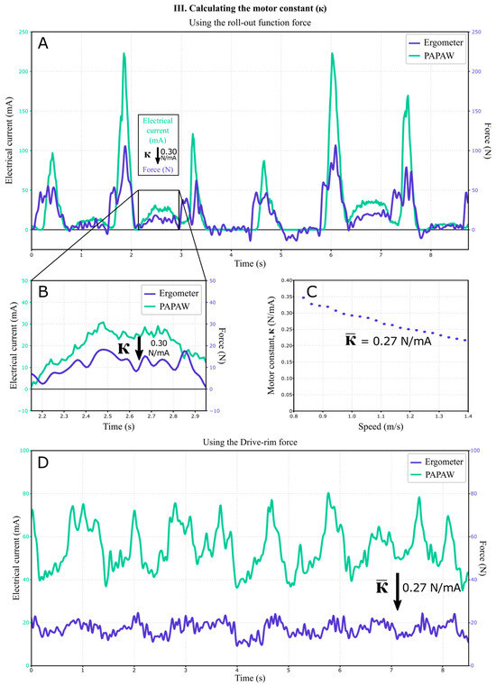
Figure 5.
(A,B): Calibration example of the PAPAW’s electrical current to the tangential force measured by the ergometer using the roll-out phase. (C): After scaling multiple roll-outs the motor constant, к (in N/mA), was determined. This example represents high assistance mode. (D): Example of drive-rim propulsion test data, represents step: 1.139 m/s.
To validate к, a second test was performed. The PAPAW used in this study (i.e., the WheelDrive) includes a drive-rim next to a standard pushrim (utilized for the current protocol). The drive-rim is a fully powered wheelchair option, where holding it in a forward position activates the electromotor, resulting in constant power output and reaching a predetermined velocity without manual propulsion (Figure 5D). This results in no WCU force application, with the electromotor’s electrical current fluctuating around the equilibrium to maintain the predetermined velocity. The velocity can be preprogrammed using the corresponding custom-made software. Given the constant electrical current signal from the PAPAW (fluctuating around the equilibrium) during drive-rim activation, it provided an extra signal for scaling with simultaneously measured ergometer force data over 21 subsequent tests, performed on one participant, each conducted at predetermined speeds ranging from 0.83 to 1.39 m/s (with uniform steps of 0.027 m/s). к was determined using the electrical current and the measured ergometer force for the left wheel data. The mean к value, derived from 1500 samples (at 100 Hz) across these 21 tests, was 0.27 N/mA (95% CI: 0.26–0.39) (Figure 5C). This value is in close agreement with the к = 0.30 calculated from the roll-outs during the initial test. According to Figure 5C, к seems to be velocity-dependent.
Furthermore, over these 21 drive-rim tests, intraclass correlations (ICCs) were computed between the converted drive-rim data (using к = 0.30 N/mA) and ergometer data. These calculations were based on a model of average measures, absolute agreement, and a two-way mixed design. The average ICC value was 0.563, indicating a moderate level of agreement between the raw ergometer data and the by к converted drive-rim (PAPAW) data. This suggests that, even though к is velocity dependent, the electrical current can be scaled using a static ratio when the velocity is closely fluctuating around the predetermined propulsion velocity.
3.4. Equipment Specific Step: Roll-Out Function Correction
During calibration, it is crucial to acknowledge that specific steps may be required depending on the type of PAPAW and/or wheelchair ergometer used. PAPAWs operate based on input algorithms, while wheelchair ergometers simulate realistic environmental conditions, including rolling resistance, through product-specific algorithms. The interaction between these algorithms can possibly lead to distortions during calibration. The following section describes an incident dependent on the equipment used in this study.
As the wheelchair ergometer used in the current study was developed for regular manual propulsion, its control algorithm does not include acceleration during the recovery phase when measuring force application (i.e., roll-out function of the PAPAW). Consequently, during the recovery phase, the ergometer’s rollers decelerate as a result of (pre)programmed drag forces when propelling with the roll-out function active (Figure 6C), similar to when the roll-out function would not be active (Figure 6B). Despite no acceleration during the recovery phase, the forces exerted by the PAPAW, triggered by the roll-out function, were still recorded. Therefore, these measurements could still be used to calculate the motor constant, as detailed in the previous sections.
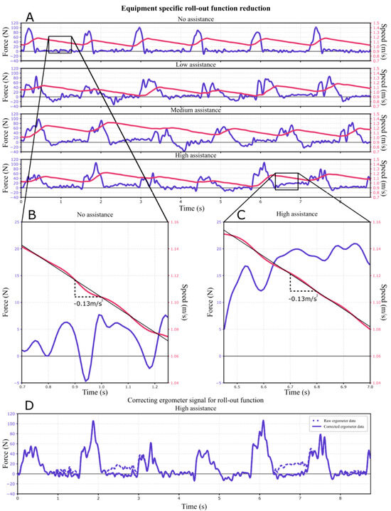
Figure 6.
(A) Comparing the effect of the roll-out force on the deceleration of the ergometer’s rollers between the four assistance modes. (B) No exerted force during the recovery, whilst the speed (red) declines by 0.13 m/s2. (C) Roll-out force is measured by the ergometer, yet does not result in acceleration or reduced deceleration, i.e., equaling the deceleration in panel a (0.13 m/s2). (D) Raw ergometer force (including roll-out; dashed line) compared to the roll-out-corrected ergometer signal (solid line).
Since the roll-out function does not account for changes in velocity, its contribution to the total power output can be neglected. Custom-written algorithms [18] were utilized to detect push and recovery phases based on the converted force signal from the PAPAW. Subsequently, all the roll-out forces were subtracted from the unprocessed ergometer force data (see Figure 6D) and from the PAPAW force data during each recovery phase. For future studies propelling the WheelDrive on a wheelchair ergometer, the roll-out function can be turned off by a professional able to access the software (i.e., a clinician). If such is not possible, the roll-out function forces can be removed from the ergometer and WheelDrive signals as mentioned above to prevent erroneous power calculations during the recovery phase. Note, not all PAPAWs are instrumented with a roll-out function.
3.5. Step IV: Separating PAPAW and WCU Forces in Ergometer Data
Following the preceding steps, the applied force by the WCUs can be determined by subtracting the force delivered by the PAPAW from the force data collected by the ergometer (see Figure 7). It is observed that the activation of the PAPAW’s electromotors is delayed compared to the onset of the WCU force. This delay may result from the processing of the force input required to activate the electromotors by the control algorithm.
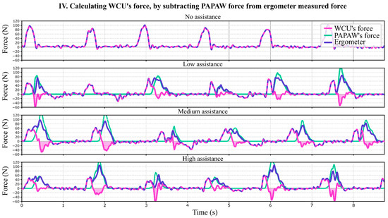
Figure 7.
The corrected ergometer force data (blue solid line) minus the PAPAW force data (green solid line) leads to the force applied by the WCU (pink solid line). Wherever the PAPAW is inactive, WCU’s force equals the force measured by the ergometer (blue/pink dashed line). Negative work of WCU during PAPAW activity is shown as the shaded pink areas. Abbreviations: WCU, wheelchair user.
According to the calculated WCU forces, negative work is performed by the WCU during the active period of the PAPAW’s electromotors (see Figure 7, shaded pink areas). These braking forces may stem from hand decoupling or dragging caused by the wheel accelerating due to the electromotor’s assistance. However, they could also arise from interaction effects between the PAPAW and wheelchair ergometer algorithms, leading to uncertainty when analyzing these negative forces. To ensure that the calculated WCU force can be entirely attributed to the WCU, a contact detection test was conducted in step V.
3.6. Step V: Markerless Motion-Capture Hand—Handrim Contact Detection
When incorporating the negative forces attributed to the WCU in step IV, push times easily exceed 0.70 s and contact angles surpass 120 degrees. In contrast, regular push times and contact angles range between 0.26 and 0.49 s and 55.1 and 83.8 degrees [5,19,20,21,22]. This observation leads to the hypothesis that the negative work, attributed to the WCU, occurs after hand contact and thus should be assigned to the PAPAW rather than the WCU. To validate whether the calculated WCU forces are indeed attributable to the WCU, a marker-less handrim contact detection test was conducted following the method outlined by Ferlinghetti et al. [23].
In this assessment, five participants completed a 4 min submaximal propulsion block (1.11 m/s, and 0.21 W/kg body mass) on the wheelchair ergometer in each assistance mode (no, low, medium, and high) using a counter-balanced order. The wheelchair ergometer collected velocity and torque data, while the PAPAW measured electrical current and velocity throughout the 4 min block. Additionally, during the last 1.5 min of each block, a RealSense Depth camera D435i (60 Hz, 848 × 480 px) (Intel, Santa Clara, CA, USA) captured video footage. The depth camera was positioned approximately at 1.0 m perpendicular to the right side of the wheel.
On the video data, a machine vision hand detection algorithm, MediaPipe [24], recognized the right hand of each individual in the RGB images, which had 21 landmarks (four for each finger and one for the wrist) (colored markings on the hand, Figure 8). Additionally, the plane of the handrim (0° camber) was determined from the RGB images (green circle, Figure 8). The position of the hand was then expressed using polar coordinates relative to the wheel, utilizing the depth images which determined the depth of both the hand and handrim (Figure 8). This method determined whether the hand had contact (i.e., on/off hand contact) with the handrim using an algorithm that evaluates five different parameters: (1) hand angular speed, (2) normal distance of the hand with respect to the handrim plane, (3) normal speed of the hand with respect to the handrim plane, (4) radial distance of the hand with respect to handrim and (5) the ratio between the hand width and height seen from the camera. For a more detailed explanation of this method and its validation, please refer to [23]. This hand contact detection method has a root-mean-square-error of 94 ms (2 × 47 ms) for the start of contact and 100 ms (2 × 50 ms) for the end of contact [23].
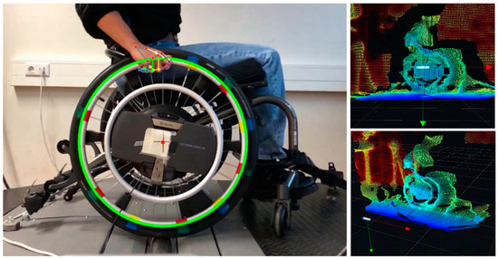
Figure 8.
Hand and handrim recognition is shown in the left panel. The two panels on the right show a point cloud containing depth data of both the hand and handrim, which are used to determine contact between them.
Contact detection using the markerless motion tracking can be compared to the push detection as it is generally determined using the ergometer data as the phase of positive power, i.e., when propulsion power exceeds zero or the level of noise during recovery [18,19,20,25]. In Figure 9, a comparison can be seen between the push detection using ergometer data and the contact detection with the depth camera data. Push initiation was later than contact initiation, and push termination earlier than contact termination. This can be explained by the fact that the hand first has to grab the handrim and then starts pushing and stops pushing before it detaches from the handrim. As a consequence, the definition of push time is not equal to contact time. Directly before and after push time, negative work is performed during the (de)coupling of the hand with the handrim [19], which is included in the definition of contact time but not in push time.
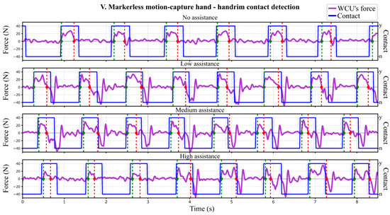
Figure 9.
Comparison between standard push detection from the ergometer data (green dashed line (start push) and red dashed line (end push)) and contact detection with depth camera footage (blue blocked line). Striped bands are root-mean-square-error bands of the contact time. Abbreviation: n; no, WCU; wheelchair user, y; yes.
The negative force, earlier attributed to the WCU in step IV (Figure 7, pink shaded areas), occurs after contact termination and is therefore not attributable to the WCU. This means that this negative force, and small positive force fluctuations afterwards, should not be included in the propulsion technique calculations of the WCU and that pushes can be identified using the regular push detection, i.e., as the propulsion power exceeds zero or the level of noise during recovery (Figure 9, green dashed lines), until propulsion power crosses back below zero or the level of noise (Figure 9, red dashed lines).
4. Discussion
This technical note aimed to describe the challenges and solutions to distinguish the force application of a WCU from forces generated by the PAPAW during manual wheelchair propulsion on a wheelchair ergometer. After collecting force and velocity data from the ergometer, and electrical current and velocity data from the PAPAW (step I), these datasets were synchronized over time (step II). Thereafter, in calibration using the roll-out function of the PAPAW, the electrical current supplied to the electromotor of the PAPAW could be scaled to force using the determined motor constant (к, in N/mA) (step III). Since the raw ergometer force data comprises the combined force exerted by both the WCU and PAPAW, subtracting the force applied by the PAPAW from the raw ergometer data provides the force attributable to the WCU (step IV). To ensure that the calculated force attributed to the WCU is accurate, hand contact with the handrim was determined using the markerless motion-capture technology, which revealed that the initial positive force of a push could be used to examine WCU propulsion technique when using a PAPAW (step V).
As mentioned in the introduction of this technical note, the PAPAW’s contribution to propulsion is currently a ‘black box’, as it cannot provide users or researchers with information about the amount and timing of assistance (e.g., in Newtons or Watts). This is because the PAPAW is not calibrated during manufacturing and hence does not provide direct information on propulsion power. To be able to perform a calibration, access to the PAPAW’s real-time data is essential (step I). To that end, for this study, the manufacturer granted access to the software specifically designed to read the electrical current and velocity from the PAPAW, which is not commercially available. Ideally, when calibration is not incorporated into the developmental stages of a PAPAW, it should be ensured that PAPAW data (e.g., electrical current) can be collected, requiring compatible software.
Aligning ergometer and PAPAW data (step II) by cross-correlation provided the opportunity to determine motor constant к (step III). Two separate methods were used to calculate к: the roll-out function and drive-Rim method. Both methods excluded the presence of any (variable) external force application and resulted in comparable values for к. During the submaximal test using the roll-out function method, the study population propelled at 1.11 m/s. For the drive-Rim method, an average к was calculated over velocities that ranged from 0.83 to 1.39 m/s in uniform steps of 0.027 m/s. This results in a proper estimation of the force contributed by the PAPAW using к when the velocity fluctuates closely around 1.11 m/s. Yet, during the drive-Rim method, к was showing a trend where it was higher at lower speeds (e.g., 0.83 m/s) and lower at higher speeds (e.g., 1.39 m/s) depending on the motor efficiency when propelling at a certain speed (Figure 5C). Therefore, when calibrating the PAPAW for a different task, such as submaximal propulsion at a different predetermined velocity or during accelerating and decelerating, the determination of к should be based on the predetermined speed or a curve derived from multiple velocities.
The calibration of the system provided some surprising observations regarding the assistance of the PAPAW and its interaction with the WCU. In addition to the determined amplitude of force, the timing of the provided assistive force can be examined as well. It can be observed in Figure 7 that between push initiation and PAPAW activation, there is a small delay. This can possibly result in the hand being slightly dragged forward due to the acceleration of the wheel, possibly causing unnecessary strain due to inefficient support timing. Hence, examining how the PAPAW provides support could lead to optimizing such a system for both the required level of assistance and timing. It would be beneficial if PAPAW developers could incorporate this calibration or integrate force sensors directly into the wheel, as seen in custom-made wheels by Khalili and colleagues [6]. However, while solely implementing force sensors only yields WCU propulsion technique results, it lacks specific insights into the PAPAW’s level and timing of assistance. This study is the first, with the use of calibration, to examine the level and timing of assistance of the PAPAW and its interaction with the WCU, which are valuable insights for the optimization of how a PAPAW supports manual propulsion.
It should be noted that the present study performed a calibration using specific equipment (the WheelDrive and Esseda wheelchair ergometer, see the equipment section). Given that all the PAPAWs and wheelchair ergometers operate on a control algorithm, certain equipment-specific steps may be necessary. In the present study, such equipment-specific steps have been taken (e.g., removing the PAPAW roll-out function’s force contribution after calibration, to ensure that power is not overestimated) that could be unnecessary or different when this calibration is performed using other equipment. Hence, when conducting a study involving a PAPAW on a wheelchair ergometer, it is important to thoroughly check the algorithms of both systems’ software to prevent any potential interactions between the two modalities, as failure to do so could lead to erroneous conclusions when examining the impact of PAPAW assistance on the WCU.
Lastly, inspecting the WCU force application with the markerless motion-capture analysis showed that the negative WCU force of hand decoupling cannot be examined with certainty. It is possible that this negative force (Figure 7, shaded pink area) is both an actual WCU force and an interaction effect between the PAPAW and wheelchair ergometer (i.e., equipment-specific interaction). Ergo, following the termination of hand contact and the active phase of the electromotors, internal friction in the components of the electromotors such as bearings and brushes might cause the wheels to decelerate, resulting in negative work. Yet, the current calibration method cannot separate what part of this negative force is attributable to the WCU and what part is equipment-specific. However, it is possible that the negative work resulting from the decoupling of the hand is larger during PAPAW-assisted propulsion than during regular handrim propulsion. This could be due to the acceleration of the wheel caused by the PAPAW’s electromotors, which might drag the hand forward. Yet, how much of this negative work after the push time is due to hand-decoupling and how this is affected by PAPAW assistance remains a topic for future studies.
Limitations
The velocity-dependent motor constant was assessed in controlled standardized conditions. However, this study does not assess all the factors that could potentially affect the electromotor’s efficiency. Such factors could also include motor load, motor maintenance, or environmental conditions (i.e., temperature or vibrations) [26,27]. Nonetheless, the current study utilized recently manufactured PAPAWs in a climate-controlled wheelchair propulsion laboratory (i.e., temperature control), minimizing the effect of maintenance and environmental factors on the electromotor’s efficiency. Future research might examine the motor constant of a PAPAW while altering factors that could affect the electromotor’s efficiency, by, for example, changing temperature in a standardized setting.
5. Conclusions
A calibration of a PAPAW on a wheelchair ergometer effectively assesses forces generated by the PAPAW and the separate force application of the WCU. Engineers and researchers could integrate this calibration method into all the PAPAW/ergometer measurement set-ups, whether for research or diagnostics. The present study demonstrated a case-specific example of a calibration, showing equipment-dependent results. Therefore, future studies should examine potential interaction effects between the utilized PAPAW and ergometer to ensure all the calculated WCU forces are accurately attributed to the WCU. This calibration provides insight into the level and timing of PAPAW assistance and the interaction of PAPAW assistance on the WCU their propulsion technique and physiological demands. These insights are crucial for optimizing PAPAW assistance.
Author Contributions
Conceptualization, J.B., S.d.G., H.H. and R.J.K.V.; methodology, J.B., S.d.G., H.H., R.J.K.V., E.F. and M.L.; formal analysis, J.B. and E.F.; investigation, J.B.; resources, J.B. and E.F.; data curation, J.B. and E.F.; writing—original draft preparation, J.B.; writing—review and editing, J.B., E.F., M.L., H.H., S.d.G. and R.J.K.V.; visualization, J.B.; supervision, R.J.K.V., S.d.G. and H.H.; project administration, R.J.K.V. All authors have read and agreed to the published version of the manuscript.
Funding
This research received no external funding.
Data Availability Statement
The raw data supporting the conclusions of this article will be made available by the authors upon request.
Acknowledgments
The authors would like to thank the people at Indes Healthcare B.V., Lode B.V., and Umaco B.V. for their ongoing collaboration and for providing the opportunity to explore the specifications and control algorithms of the PAPAW and wheelchair ergometer.
Conflicts of Interest
Although there have been dialogues with employees from Indes Healthcare B.V. and Umaco B.V., they did not have any role in decisions with regard to the design of this study, data collection, analysis, interpretation of data, or in the decision of what to publish.
References
- Kloosterman, M.G.M.; Snoek, G.J.; Van Der Woude, L.H.V.; Buurke, J.H.; Rietman, J.S. A Systematic Review on the Pros and Cons of Using a Pushrim-Activated Power-Assisted Wheelchair. Clin. Rehabil. 2013, 27, 299–313. [Google Scholar] [CrossRef] [PubMed]
- Boninger, M.L.; Waters, R.L.; Chase, T.; Dijkers, M.P.J.M.; Gellman, H.; Gironda, R.J.; Goldstein, B.; Johnson-Taylor, S.; Koontz, A.; McDowell, S.L. Preservation of Upper Limb Function Following Spinal Cord Injury: A Clinical Practice Guideline for Health-Care Professionals (Reprinted). J. Spinal Cord Med. 2005, 28, 433–470. [Google Scholar] [CrossRef]
- Moon, Y.; Jayaraman, C.; Hsu, I.M.K.; Rice, I.M.; Hsiao-Wecksler, E.T.; Sosnoff, J.J. Variability of Peak Shoulder Force during Wheelchair Propulsion in Manual Wheelchair Users with and without Shoulder Pain. Clin. Biomech. 2013, 28, 967–972. [Google Scholar] [CrossRef]
- Rice, I.M.; Jayaraman, C.; Hsiao-Wecksler, E.T.; Sosnoff, J.J. Relationship between Shoulder Pain and Kinetic and Temporal-Spatial Variability in Wheelchair Users. Arch. Phys. Med. Rehabil. 2014, 95, 699–704. [Google Scholar] [CrossRef] [PubMed]
- Braaksma, J.; Vegter, J.K.; Leving, M.T.; Van Der Scheer, J.W.; Tepper, M.; Woldring, F.A.B.; Van Der Woude, L.H.V.; Houdijk, H.; De Groot, S. Handrim Wheelchair Propulsion Technique in Individuals With Spinal Cord Injury With and Without Shoulder Pain A Cross-Sectional Comparison. Am. J. Phys. Med. Rehabil. 2023, 102, 886–895. [Google Scholar] [CrossRef]
- Guillon, B.; Van-Hecke, G.; Iddir, J.; Pellegrini, N.; Beghoul, N.; Vaugier, I.; Figère, M.; Pradon, D.; Lofaso, F. Evaluation of 3 Pushrim-Activated Power-Assisted Wheelchairs in Patients with Spinal Cord Injury. Arch. Phys. Med. Rehabil. 2015, 96, 894–904. [Google Scholar] [CrossRef]
- Nash, M.S.; Koppens, D.; van Haaren, M.; Sherman, A.L.; Lippiatt, J.P.; Lewis, J. Power-Assisted Wheels Ease Energy Costs and Perceptual Responses to Wheelchair Propulsion in Persons With Shoulder Pain and Spinal Cord Injury. Arch. Phys. Med. Rehabil. 2008, 89, 2080–2085. [Google Scholar] [CrossRef] [PubMed]
- Haubert, L.; Requejo, P.; Newsam, C.; Mulroy, S. Comparison of Energy Expenditure and Propulsion Characteristics in a Standard and Three Pushrim-Activated Power-Assisted Wheelchairs. Top. Spinal Cord. Inj. Rehabil. 2005, 11, 64–73. [Google Scholar] [CrossRef]
- Algood, S.D.; Cooper, R.A.; Fitzgerald, S.G.; Cooper, R.; Boninger, M.L. Impact of a Pushrim-Activated Power-Assisted Wheelchair on the Metabolic Demands, Stroke Frequency, and Range of Motion Among Subjects with Tetraplegia. Arch. Phys. Med. Rehabil. 2004, 85, 1865–1871. [Google Scholar] [CrossRef]
- Khalili, M.; Kryt, G.; van der Loos, H.F.M.; Borisoff, J.F. A Comparison between Conventional and User-Intention-Based Adaptive Pushrim-Activated Power-Assisted Wheelchairs. IEEE Trans. Neural Syst. Rehabil. Eng. 2021, 29, 2511–2520. [Google Scholar] [CrossRef]
- Khalili, M.; McConkey, K.T.; Ta, K.; Wu, L.C.; van der Loos, H.F.M.; Borisoff, J.F. Development of A Learning-Based Terrain Classification for Pushrim-Activated Power-Assisted Wheelchairs. Annu. Int. Conf. IEEE Eng. Med. Biol. Soc. 2020, v2020, 4762–4765. [Google Scholar] [CrossRef]
- Seki, H.; Tanohata, N. Fuzzy Control for Electric Power-Assisted Wheelchair Driving on Disturbance Roads. IEEE Trans. Syst. Man. Cybern. Part. C Appl. Rev. 2012, 42, 1624–1632. [Google Scholar] [CrossRef]
- Seki, H.; Ishihara, K.; Tadakuma, S. Novel Regenerative Braking Control of Electric Power-Assisted Wheelchair for Safety Downhill Road Driving. IEEE Trans. Ind. Electron. 2009, 56, 1393–1400. [Google Scholar] [CrossRef]
- Khalili, M.; Kryt, G.; Mortenson, W.B.; Van der Loos, H.F.M.; Borisoff, J. Comparison of Manual Wheelchair and Pushrim-Activated Power-Assisted Wheelchair Propulsion Characteristics during Common over-Ground Maneuvers. Sensors 2021, 21, 7008. [Google Scholar] [CrossRef] [PubMed]
- Arva, J.; Fitzgerald, S.G.; Cooper, R.A.; Boninger, M.L. Mechanical Efficiency and User Power Requirement with a Pushrim Activated Power Assisted Wheelchair. Med. Eng. Phys. 2001, 23, 699–705. [Google Scholar] [CrossRef] [PubMed]
- Digiovine, C.P.; Cooper, R.A.; Boninger, M.L. Dynamic Calibration of a Wheelchair Dynamometer. J. Rehabil. Res. Dev. 2001, 38, 41–55. [Google Scholar] [PubMed]
- Cooper, R.A.; Corfman, T.A.; Fitzgerald, S.G.; Boninger, M.L.; Spaeth, D.M.; Ammer, W.; Arva, J. Performance Assessment of a Pushrim-Activated Power-Assisted Wheelchair Control System. IEEE Trans. Control. Syst. Technol. 2002, 10, 121–126. [Google Scholar] [CrossRef]
- De Klerk, R.; Rietveld, T.; Janssen, R.J.F.; Braaksma, J. Worklab: A Wheelchair Biomechanics Mini-Package. Zenodo 2023. [Google Scholar] [CrossRef]
- Vegter, R.J.K.; de Groot, S.; Lamoth, C.J.; Veeger, D.H.; van der Woude, L.H. V Initial Skill Acquisition of Handrim Wheelchair Propulsion: A New Perspective. IEEE Trans. Neural Syst. Rehabil. Eng. 2014, 22, 104–113. [Google Scholar] [CrossRef]
- De Groot, S.; Veeger, D.H.E.J.; Hollander, A.P.; Lucas, L.H. Wheelchair Propulsion Technique and Mechanical Efficiency after 3 Wk of Practice. Med. Sci. Sports Exerc. 2002, 34, 756–766. [Google Scholar] [CrossRef][Green Version]
- De Groot, S.; Cowan, R.E.; MacGillivray, M.K.; Leving, M.T.; Sawatzky, B.J. The Effect of External Power Output and Its Reliability on Propulsion Technique Variables in Wheelchair Users with Spinal Cord Injury. IEEE Trans. Neural Syst. Rehabil. Eng. 2022, 30, 296–304. [Google Scholar] [CrossRef] [PubMed]
- de Groot, S.; Vegter, R.J.K.; van der Woude, L.H.V. Effect of Wheelchair Mass, Tire Type and Tire Pressure on Physical Strain and Wheelchair Propulsion Technique. Med. Eng. Phys. 2013, 35, 1476–1482. [Google Scholar] [CrossRef] [PubMed]
- Ferlinghetti, E.; Salzmann, I.; Ghidelli, M.; Rietveld, T.; Vegter, R.; Lancini, M. Algorithm Development for Contact Identification during Wheelchair Tennis Propulsion Using Marker-Less Vision System. In Proceedings of the 2023 IEEE International Symposium on Medical Measurements and Applications (MeMeA), Jeju, Republic of Korea, 14–16 June 2023; IEEE: New York, NY, USA; pp. 1–6. [Google Scholar]
- Zhang, F.; Bazarevsky, V.; Vakunov, A.; Tkachenka, A.; Sung, G.; Chang, C.-L.; Grundmann, M. MediaPipe Hands: On-Device Real-Time Hand Tracking. arXiv 2020, arXiv:2006.10214. [Google Scholar]
- van Drongelen, S.; van der Woude, L.H.V.; Veeger, H.E.J. Load on the Shoulder Complex during Wheelchair Propulsion and Weight Relief Lifting. Clin. Biomech. 2011, 26, 452–457. [Google Scholar] [CrossRef]
- Rigacci, M.; Sato, R.; Shirase, K. Evaluating the Influence of Mechanical System Vibration Characteristics on Servo Motor Efficiency. Precis. Eng. 2021, 72, 680–689. [Google Scholar] [CrossRef]
- Li, Y.; Liu, M.; Lau, J.; Zhang, B. A Novel Method to Determine the Motor Efficiency under Variable Speed Operations and Partial Load Conditions. Appl. Energy 2015, 144, 234–240. [Google Scholar] [CrossRef]
Disclaimer/Publisher’s Note: The statements, opinions and data contained in all publications are solely those of the individual author(s) and contributor(s) and not of MDPI and/or the editor(s). MDPI and/or the editor(s) disclaim responsibility for any injury to people or property resulting from any ideas, methods, instructions or products referred to in the content. |
© 2024 by the authors. Licensee MDPI, Basel, Switzerland. This article is an open access article distributed under the terms and conditions of the Creative Commons Attribution (CC BY) license (https://creativecommons.org/licenses/by/4.0/).