Article

New Tuning Rules of PI+CI Controllers for First-Order Systems

Department of Informatics, University of Almería, CIESOL, ceiA3, 04120 Almería, Spain
*
Author to whom correspondence should be addressed.
Actuators 2024, 13(2), 67; https://doi.org/10.3390/act13020067
Submission received: 12 January 2024 / Revised: 8 February 2024 / Accepted: 9 February 2024 / Published: 11 February 2024
(This article belongs to the Special Issue New Control Schemes for Actuators—2nd Edition)

Abstract

:
The reset control is a simple nonlinear control approach where the states of the controller are conducted to zero when a particular condition is satisfied. The PI+CI is a controller that mixes the simplicity of PI controllers with the benefits of a reset action to mitigate the fundamental limitations of linear control. However, the tuning of this kind of controller, with three parameters, two for the linear part and one for the nonlinear one, is not trivial. In this paper, simple tuning rules for PI+CI are proposed for both tracking and regulation problems, assuming first-order dynamics for the plant. The resulting control scheme, for which the reset coefficient is computed from exponential functions, is simulated and compared with an ideal PI+CI where the reset coefficient is obtained using rules available in the literature. Similar results are obtained for the tracking problem, and optimal performance based on the Integral Absolute Error (IAE) is also obtained for the regulation problem. These new rules, in contrast to those already existing in the literature, depend only on closed-loop specifications. Furthermore, the framework based on the minimization of IAE, used to obtain the proposed rules, makes it possible to consider for the first time the tracking and regulation problems simultaneously, i.e., cases where setpoint changes and disturbance arrivals can occur at the same time before reaching a new steady state. The results are validated using a set of study cases.

1. Introduction

Reset control systems are a kind of nonlinear controller that are characterized for forcing the states of the controllers to zero when a specific condition is satisfied. These controllers contribute to overcome some limitations of linear controllers, such as those related to sensor noise amplification when the controller gain is increased to augment the controller phase. With reset controllers, it is possible to increase the phase only slightly, affecting the gain increase and thus also improving the system stability. In the seminal work [1], Clegg proposed the first reset system, which was a nonlinear integrator with the output driven to zero when the input was also equal to zero. This integrator was named Clegg’s integrator (CI). After that, several works were developed, but it was after the group of works by Horowitz, Rosenbaum and Krishman [2,3,4] when reset control systems were definitely driven by the introduction of the first-order reset element.
Since 1958, around 400 papers have been published on reset control (see [5] for a detailed chronological review). Many of them had theoretical developments and many others were of a practical nature. Precision motion, automotive industry, energy, robotics, chemical industry, and aircrafts are some examples of application domains. New reset control strategies have recently been developed, in particular, a single structure based on a combination of the PI controller and Clegg’s integrator, the PI+CI [6], which is the control algorithm analyzed in this work. This controller combines the simplicity of a PI controller (present in 90% of industrial applications [7]) with the advantages of reset action. However, this strategy must be used carefully, because the reset action may make the LTI control system base unstable [8]. This single nonlinear strategy has been used in different applications. For example, in [9], it is applied to the temperature control of a heat exchanger; in [10], it is used for the pH control of a pilot plant in the food industry and the liquid level tank control; in [11], it is applied for the regulation of voltage in a DC microgrid with fuel cell-supercapacitor-based storage elements; and in [12], it is considered to control pH in an industrial photobioreactor for microalgae production. Nevertheless, stability and/or decreased performance problems may occur if the PI+CI parameters are not adequately tuned. For stability analysis, in general, an approximation based on the describing function is used for the nonlinear PI+CI controller, but this approximation is not necessary for the case of first-order systems, where closed-loop stability is ensured if the base linear system is stable [13]. After the first work on the PI+CI control [13], new contributions have appeared that propose tuning methods for the PI+CI controller. For example, in refs. [14,15,16], adaptive strategies based on optimization procedures are used to estimate the optimal values inline for the controller parameters. Analytical methods have also been used in some papers, for example, in refs. [17,18], to obtain tuning rules that can be used offline based on the states of the system at particular times. Other related works use PID compensation with full reset action, and not partial compensation as the PI+CI controller, such as [19,20]. In refs. [21,22,23], reset compensation is also applied to control systems without delay.
Therefore, the existing tuning rules are based on optimization approaches or on offline methods that consider the process parameters and the states of the system that must be estimated inline to calculate the controller parameters. In this paper, a different approach is presented based on a systematic method for the design of the PI+CI controller. The solution is based on analytical rules that are calculated on the basis of the minimization of the Integral Absolute Error (IAE) of the closed-loop response. The resulting rules depend only on two closed-loop parameters, the damping factor and the peak time. These rules allow us to achieve an optimum flat response for first-order systems for both tracking and regulation problems. The proposed solution is evaluated in simulation in different scenarios to show its control capabilities.
The paper is organized as follows. The fundamentals of the PI+CI controller are briefly presented in Section 2. Subsequently, in Section 3, tuning rules for tracking and regulation problems are derived, and the proposed control algorithm is described. In Section 4, the discussion on a set of study cases is provided to validate the results. Section 5 presents an example of a nonlinear system that can be approximated by a first-order model around an operation point. Finally, the paper ends with conclusions and future works.

2. Fundamentals of PI+CI Controller

The PI+CI is based on a PI controller with a linear integrator connected in parallel with Clegg’s integrator. So, the PI+CI controller has three terms in parallel: proportional term (P), integral term (I) and Clegg’s integrator (CI), as shown in Figure 1. The PI controller, now named the base PI controller, is given by:
u ( t ) = k p e ( t ) + 1 τ i 0 t e ( υ ) d υ , when   p r = 0
where k p is the propotional gain, τ i is the integral time, and Clegg’s integrator is given by [6]:
u ˙ C I ( t ) = e ( t ) when   e ( t ) 0 , u C I ( t + ) = 0 when   e ( t ) = 0
Thus, the controller parameters are k p and τ i , for the base PI controller, and  p r (reset coefficient) to fix the relative weight of the reset action on the control signal with a value between 0 and 1. When p r is equal to zero, there is no reset action and PI+CI works as a classical PI, and when p r = 1 , the controller will work as a P+CI. For values greater than 0 and less than 1, the aggressiveness of the control signal could be modulated.
In state space, the PI+CI controller can be expressed using two states: one for the integral term of the PI ( x i ) and the other one for the Clegg integrator ( x c i ). Thus, the state will be x r = ( x i , x c i ) . A PI+CI state-space model is given by Equation (3) [6]
x ˙ r = B r e , e 0 x r + = A ρ x r , e = 0 v = C r x r + D r e
where x r + , or  x r ( t + ) , represents the value x r ( t + ϵ ) with ϵ 0 + , and the matrices B r , A ρ , C r , and  D r are given by
B r = 1 1 ,   A ρ = 1 0 0 0
C r = k p τ i 1 p r p r ,   D r = k p
As discussed previously, three parameters must be calculated ( k p , τ i and p r ). The parameter p r of Clegg’s integrator is tuned to improve the performance of the linear controller, and the base PI is tuned so that, partly by resetting its state, the closed-loop performance can be improved. Therefore, in the first place, a fast response with significant overshoot will be specified for the base PI controller and after that, the partial reset ( p r ) will be used to decrease the resulting overshoot, maintaining the speed of response.
In the case of first-order systems, described by the following transfer function
P ( s ) = k τ s + 1
a flat response for disturbance rejection (regulation problem) can be obtained after the first reset time when p r is given by [18]
p r = e α π β 1 + e α π β
where α and β are given by
α = 1 + k p k 2 τ
and
β = + α 2 k p k τ τ i
with k and τ representing the static gain and the time constant, respectively, for the first-order system in (4), and where α 2 < K p K τ τ i is assumed to assure an oscillatory output. If Equation (5) is used for tracking step signals (tracking problem), a flat output is obtained after the second reset instant. Regarding robustness, PI+CI is robust enough if the gain of the process, k, is well modeled with low variations for the tracking problem and if the damping ratio of the closed-loop poles has low variation for the regulation problem [18]. The base PI and PI+CI exhibit similar performance in terms of cost of feedback (sensor noise effect) for both problems, considering the tracking of reference signals and disturbance rejection independently. It is also possible to obtain a flat response after the first reset instant for the tracking problem, using p r given by
p r = 1 τ i k k p x i ( t 1 )
where x i ( t 1 ) is the state of the integral term for the first reset instant [18]. However, it is not possible to obtain an explicit solution for it.
Let us use an example to show the performance of the previous rules. The process is given by the following transfer function.
G ( s ) = 3 2 s + 1
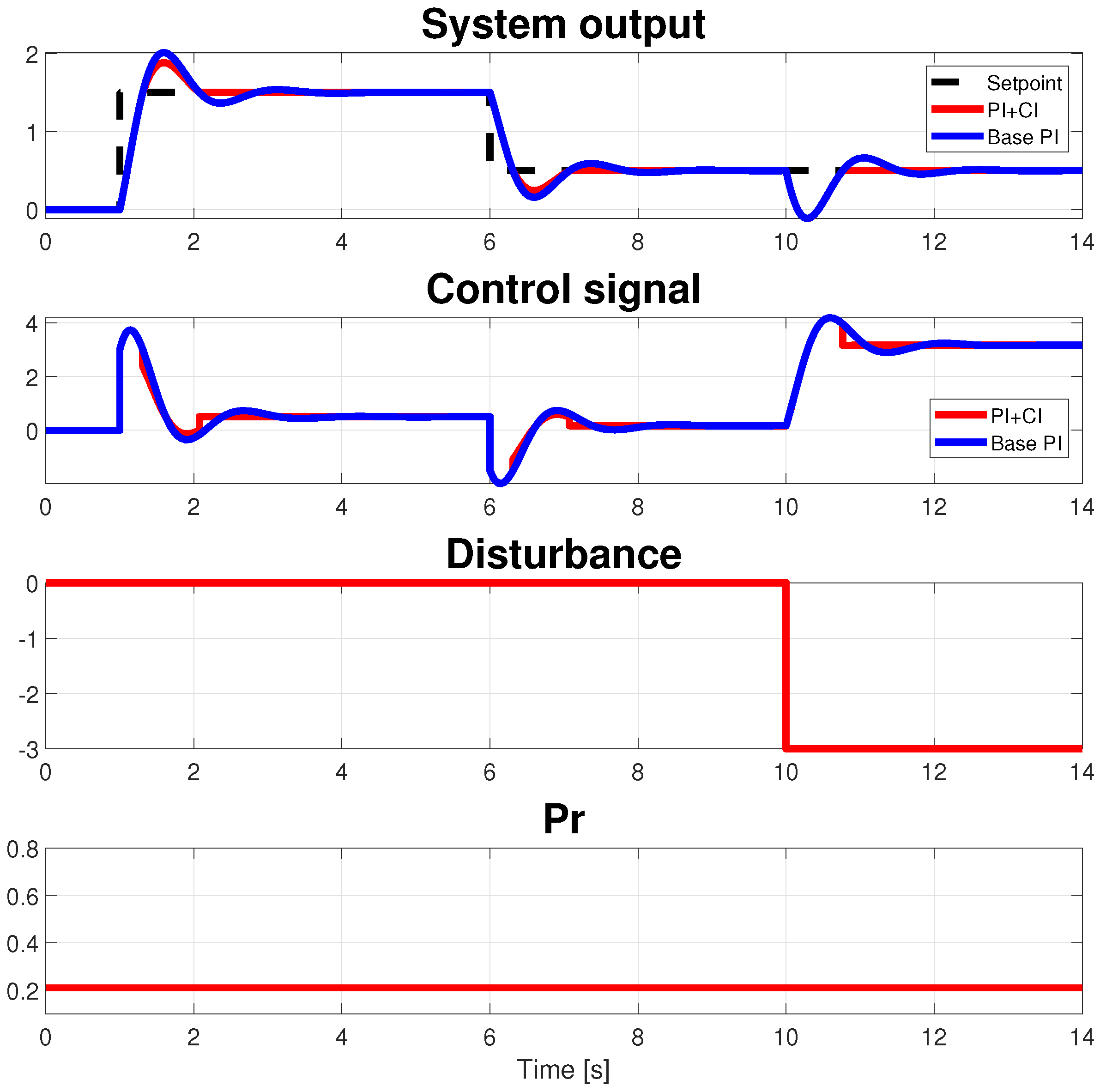
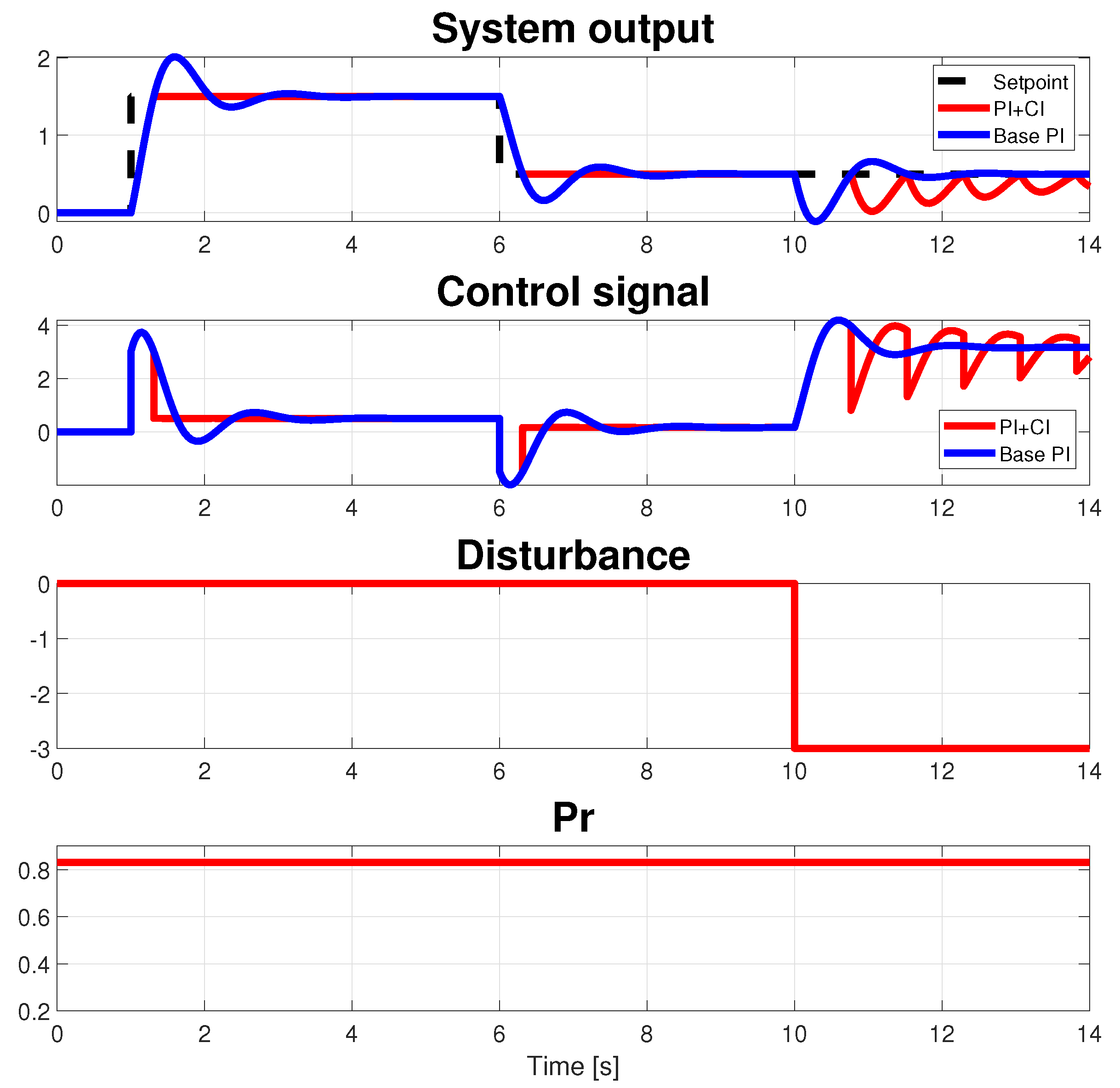
and base PI is given by ( k p = 2 , τ i = 0.15 ), from [18]. A scenario where two reference changes with different signs and a disturbance appear in steady state is considered. Figure 2 shows a performance comparison between the base PI and the PI+CI, when p r = 0.21 from Equation (5) is computed. A flat response is obtained after the second reset time in the tracking problem (first and second setpoint changes in steady state) and after the first reset time in the regulation problem (when disturbance occurs in steady state). In order to study the regulation problem, a step disturbance with an amplitude of −3 at time 10 s has been introduced. In Figure 3, the same comparison is shown, but using p r = 0.83 calculated from Equation (8), where x i ( t 1 ) = 0.1471 is obtained on line [18]. In the latter case, the response for a tracking problem is optimum, but for a regulation problem, it is not adequate. For the base PI, an IAE (Integral Absolute Error) of 1.30 is obtained vs. the value of 0.96 resulting for PI+CI with a flat response. It is important to note that a flat response is impossible to obtain if an LTI controller is used.
From Equation (5) for the regulation problem and (8) for the tracking case, the reset ratio depends on the process gain and the time constant, and in this last case, it also depends on the state of the controller. However, as shown in the following section, equivalent tuning rules may be obtained that depend only on the closed-loop specification.

3. New Tuning Rules for PI+CI

In this section, new tuning rules are proposed for the PI+CI controller based on IAE minimization. A minimum IAE is ensured if a flat output, i.e., without oscillations, is reached after the first reset time. As shown in the previous section, to study this behavior, tracking and regulation problems must be independently analyzed. Global search optimization algorithms from the MATLAB optimization toolbox are used to compute the optimum reset ratio.

3.1. Tracking Problem

On the basis of the IAE, a sweep is made considering a set of sufficiently different plants. For each combination of static gain ( k [ 1 , 10 ] ) and time constant ( τ [ 1 , 10 ] ) s, the reset ratio p r , belonging to [ 0 , 1 ] , is calculated to ensure the minimum IAE, using a unit step as a reference. The pole placement method is used to design the base PI:
( k p , τ i ) = 2 τ ξ ω n 1 k , 2 τ ξ ω n 1 τ ω n 2
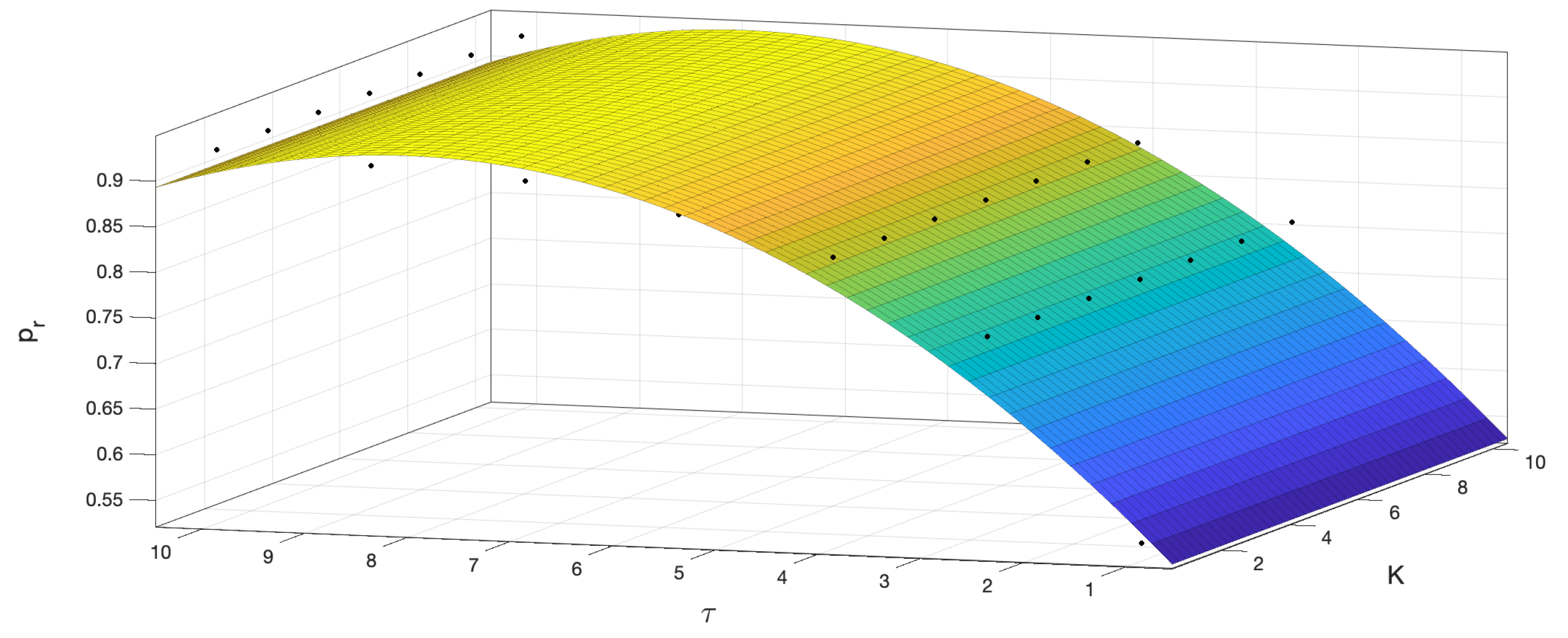
The specifications are given by a damping factor ξ = 0.33 and an undamped natural frequency ω n = 2.21 rad/s, corresponding to an overshooting of 33% and a peak time of 1.51 s, which is sufficient to obtain a fast response for the plants in the set considered. The reset ratio is swept in the interval [ 0 , 1 ] , and the minimum IAE value is chosen for each combination (k, τ ). Figure 4 shows the relationship between the best p r (minimum IAE) and the gain and the time constant of the system.
Using the MATLAB Curve-Fitting toolbox, the following equation is obtained for the curve in Figure 4:
p r ( k , τ ) = 0.46 + 5.14 · 10 17 k + 0.12 τ 4.10 · 10 18 k 2 + 2.43 · 10 18 k τ 0.01 τ 2
It is important to note that the terms for the gain k in the previous expression are too small, as also can be deduced from Figure 4, and therefore they can be omitted. Once the k terms are omitted, a more precise equation can be obtained based on a fifth-order polynomial, as follows:
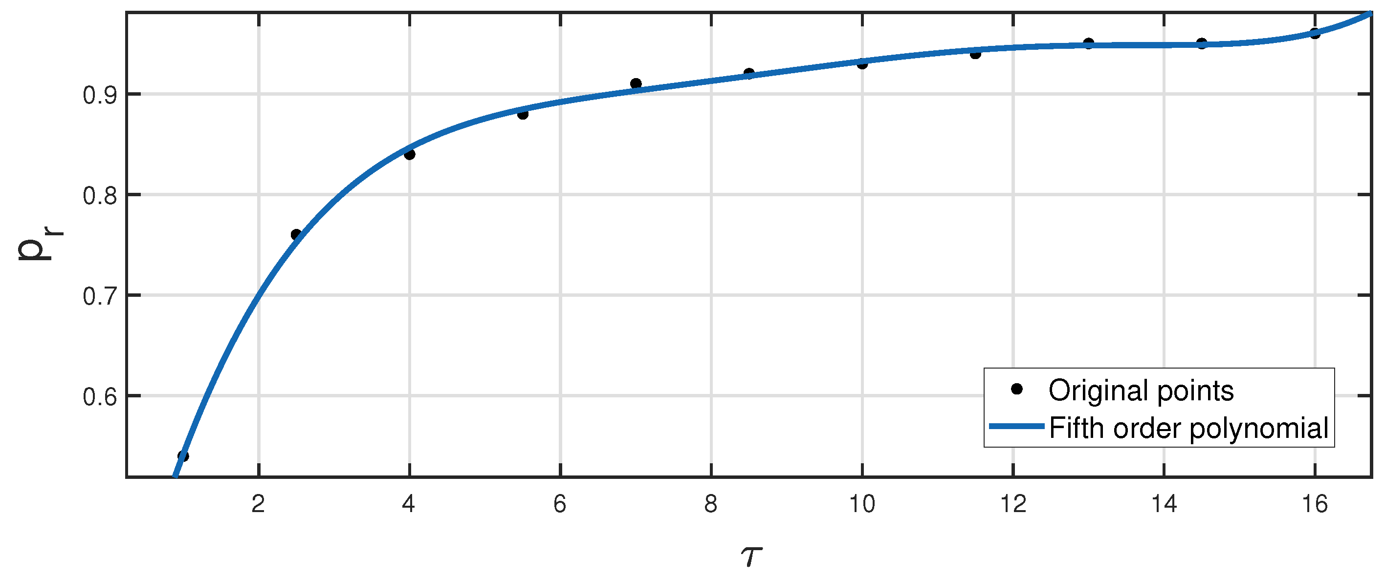
p r ( τ ) = 0.21 + 0.44 τ 0.14 τ 2 + 0.02 τ 3 1.75 · 10 3 τ 4 + 5.49 · 10 5 τ 5
Figure 5 shows the validation of this equation, where it can be observed that the proposed expression works properly for different values of τ .
However, the proposed polynomial solution is not bounded and, as previously mentioned, p r must be in the [ 0 , 1 ] interval. Therefore, for values of τ outside the range [ 1 , 10 ] , p r in [ 0 , 1 ] is not guaranteed. So, a different kind of fitting function must be used, and thus the following exponential function is proposed
p r ( τ ) = 1 e f ( τ )
where
f ( τ ) = 1.12 · 10 5 τ 5 + 0.54 · 10 3 τ 4 0.01 τ 3 + 0.11 τ 2 0.72 τ 0.16
Figure 6 shows the validation for Equation (11). As observed, for large values of the time constant, p r becomes equal to 1, and for very low values, p r 0.15 . Therefore, Equation (11) is also valid for ( k , τ ) outside the domain [ 1 , 10 ] × [ 1 , 10 ] considered for sweep. For the particular case of an integrator plant ( τ + ), p r is equal to 1, which is in line with the results in [18].
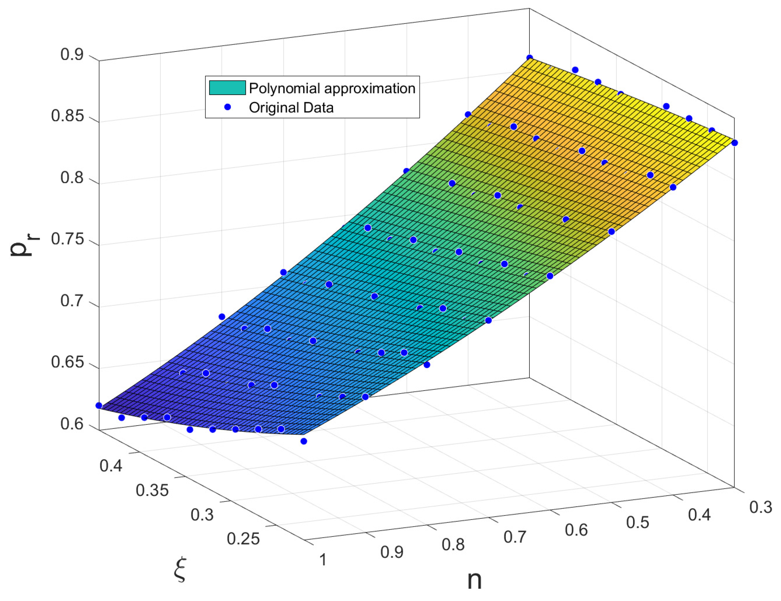
Note that the assumption of ξ = 0.33 for a PI+CI is adequate independently of the dynamic of the process (to achieve a sufficiently oscillatory response as suggested in [9]); however, the value of ω n = 2.21 (peak time of 1.51 s) may not be adequate for a process with a time constant less than one. On the other hand, as will be shown in the next section, for the regulation problem, p r depends only on the damping factor. So, in order to study the optimum value of p r for both the tracking problem and the regulation, the tracking problem must also be analyzed in terms of this parameter. The previous study shows the independence of p r with respect to the gain of the process. Therefore, a new study is considered in which the sweep is carried out only on parameters ξ and n = t p / τ , with  t p being the peak time. A  t p between 0.3 τ and τ , and  ξ between 0.22 and 0.46 (overshoot between 20% and 50%) are considered. Notice that this value for the overshoot ensures a sufficiently oscillatory response as suggested in [9]. Values over 0.46 give oscillations smaller than 20%, which does not justify the need for a reset element. On the other hand, the value of 0.22 provides just an overshoot of 50%, which is a too aggressive specification. Smaller values of the damping factor would provoke too large control signal peaks and leave the system in permanent saturation during the transient period. For the peak time, an interval between 30% and 100% of the open-loop time constant has been chosen, but without loss of generality, the same procedure presented below can be applied using a different interval. Figure 7 shows the result of this sweep and the fit given by the following polynomial.
p r ( ξ , n ) = 0.95 + 0.24 ξ 0.32 ξ 2 0.20 n 0.91 ξ n + 0.68 ξ 2 n + 0.13 ξ n 2

3.2. Regulation Problem

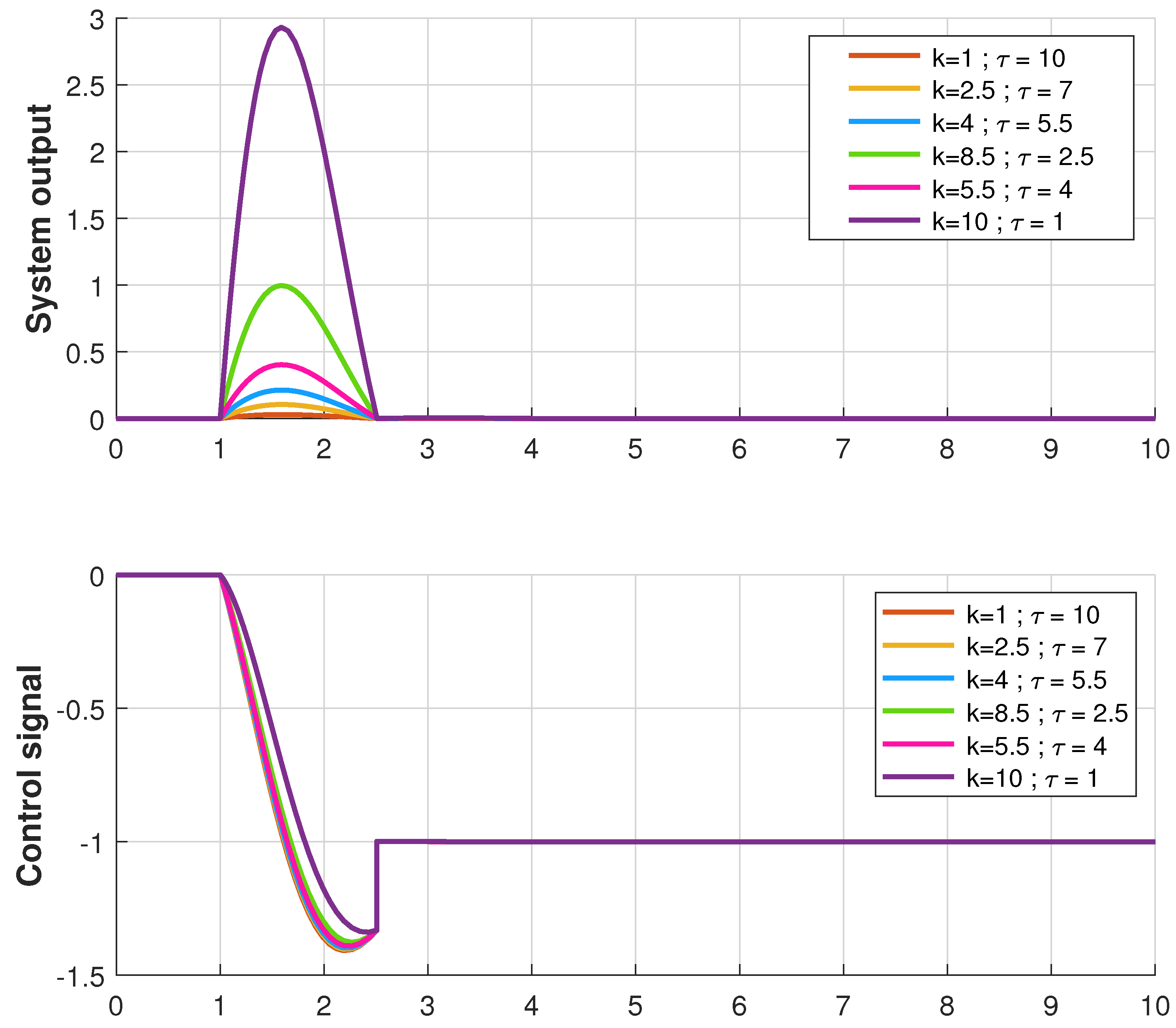
Following the same procedure presented in the previous section, a sweep is carried out on the parameters k and τ to obtain p r to ensure the minimum IAE for the disturbance rejection problem. However, in this case, the value of the reset ratio obtained is always p r = 0.25 . Figure 8 shows the response of some representative plants.
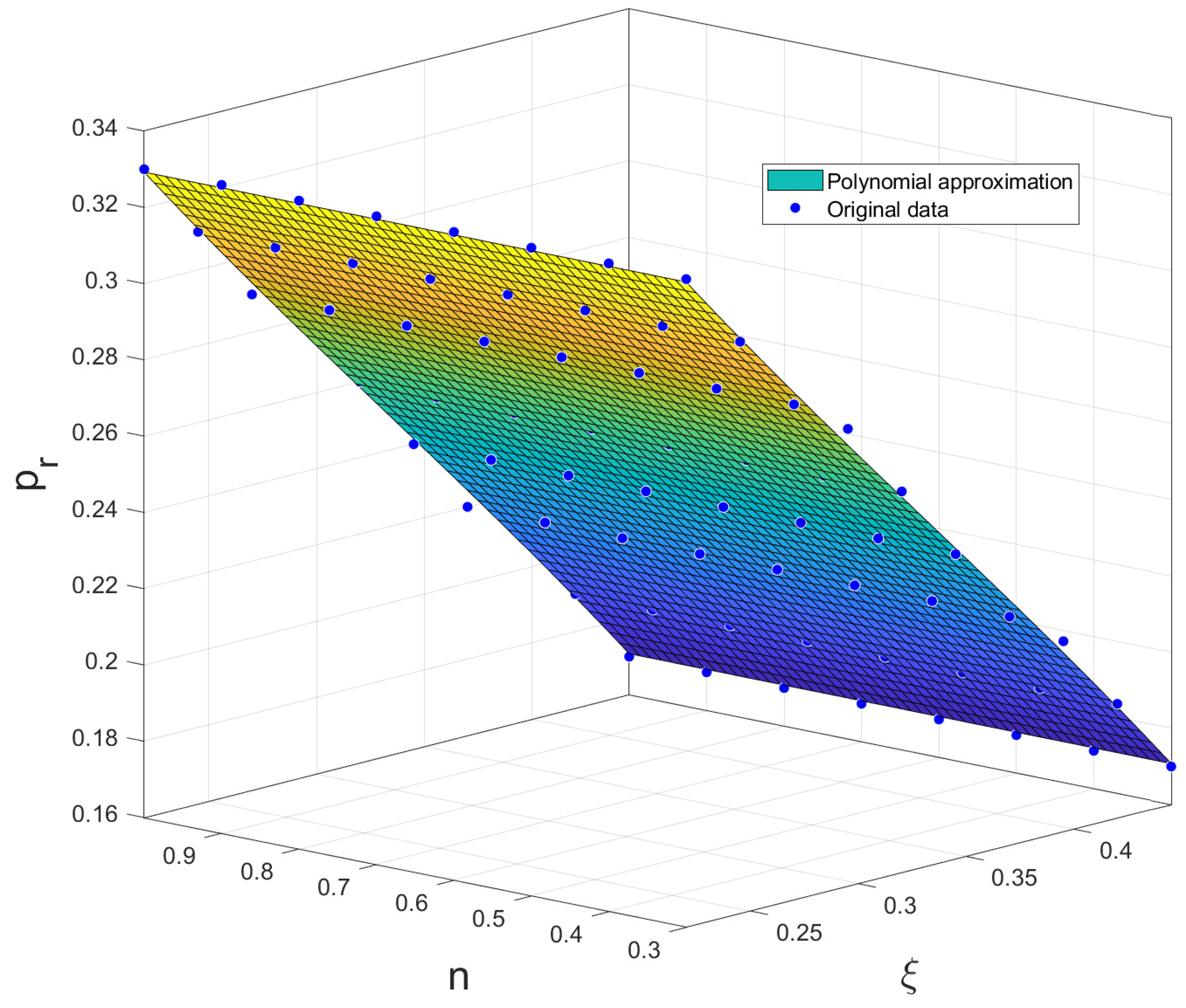
Therefore, p r does not depend on the dynamics of the process. As in the previous case, it depends only on the closed-loop specifications. Making exactly the same sweep as in the tracking case, the third-order polynomial in Equation (13) is calculated to fit the data, as Figure 9 shows.
p r ( ξ , n ) = 0.54 1.26 ξ + 1.74 ξ 2 1.74 ξ 3 + A ( ξ , n )
where
A ( ξ , n ) = 10 15 · ( 8.60 ξ n 3.17 ξ 2 n 4.36 ξ n 2 4.22 n + 4.23 n 2 1.44 n 3 )
which can be neglected. So, p r only depends on ξ , as follows:
p r ( ξ ) = 0.54 1.26 ξ + 1.74 ξ 2 1.74 ξ 3
To validate this new rule to obtain p r for the regulation problem, the value ξ = 0.33 is used in Equation (14), resulting in p r = 0.25 as expected.

3.3. Combined Tracking and Regulation Problems

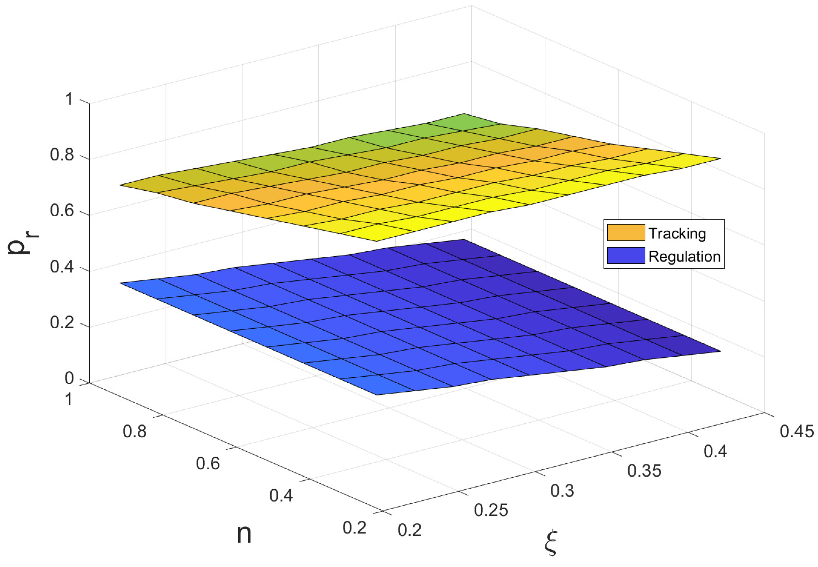
When tracking and regulation problems are considered at the same time, the optimum p r must belong to the surfaces in Figure 7 and Figure 9. Figure 10 shows both surfaces in the same plot. As observed, the surfaces do not intersect, and thus it is not possible to obtain a flat response after the first reset instant for tracking and regulation simultaneously.
Therefore, a possible solution is to use the scheme in Figure 11, where the optimal p r is selected ( p r t for the tracking problem from Equation (12) and p r r for regulation from Equation (14)) based on changes in inputs (measurable disturbances are assumed). Notice that measurable disturbances are common in the process industry, such as pressure, temperature, solar radiation, wind speed, flow rate, etc. To ensure smooth transfer between switchings, a tracking mode option is included in the controllers using T t = τ i [24].
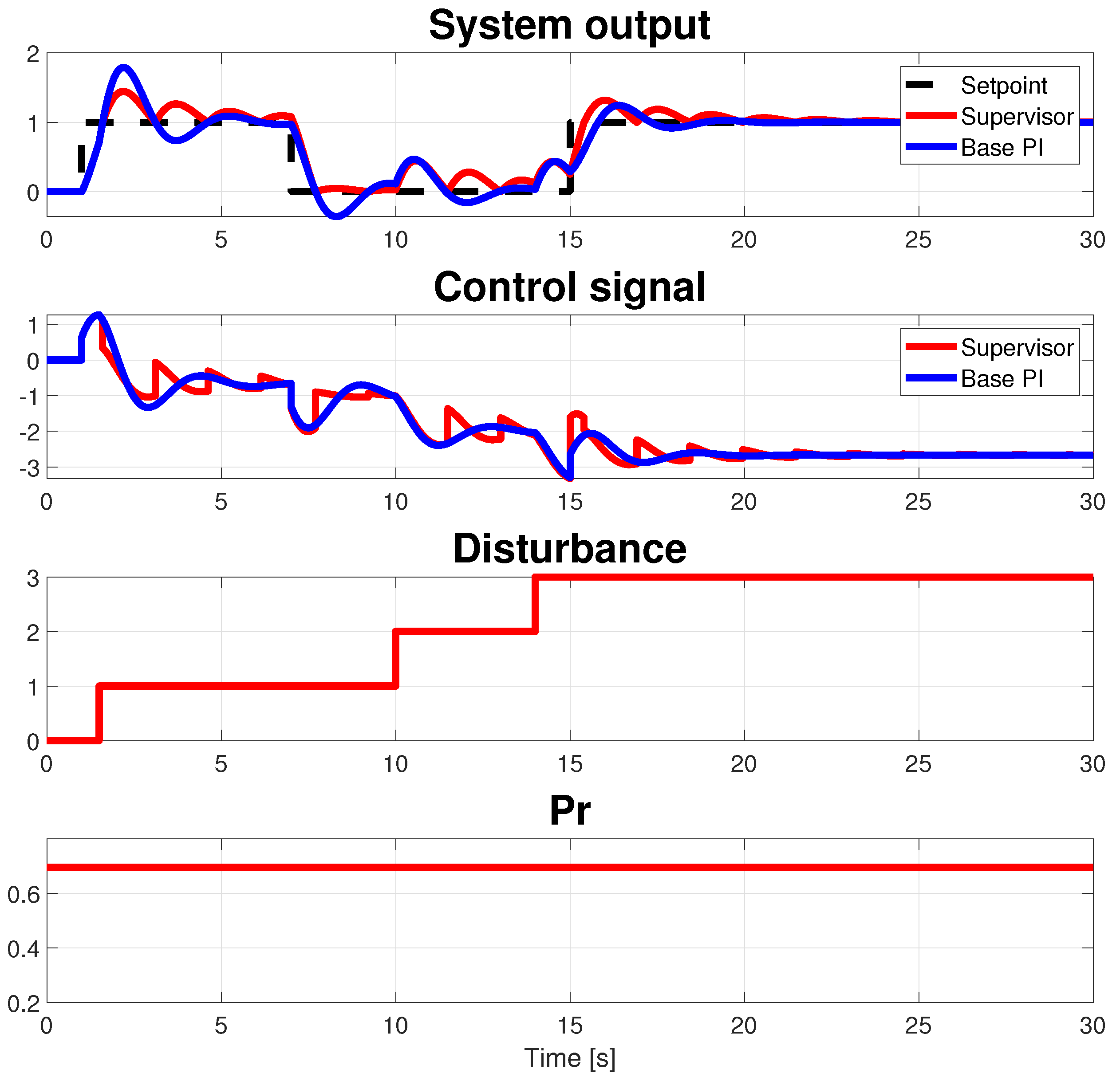
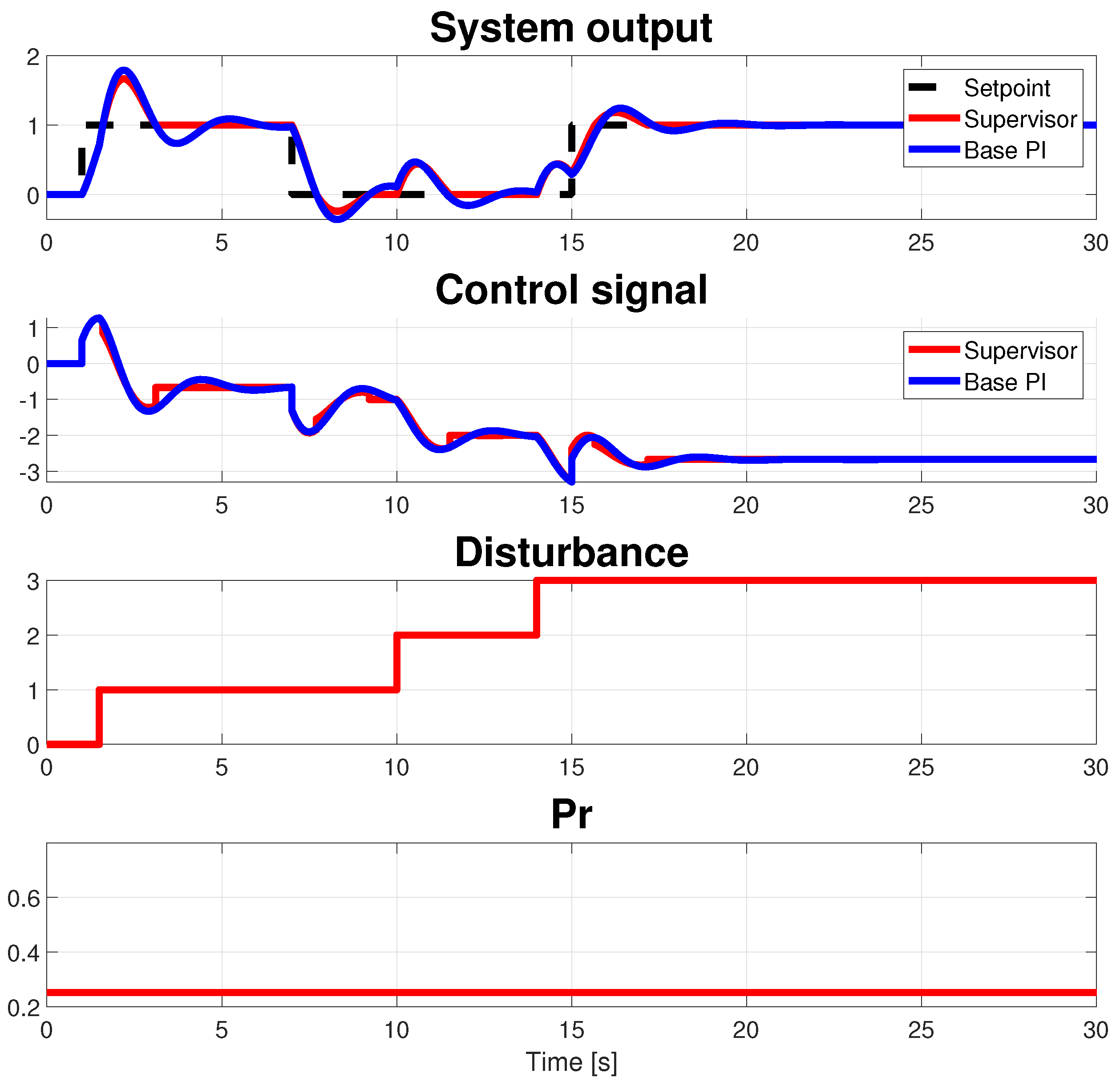
Now, two cases are considered to set the supervisor behavior up: when a disturbance appears during a setpoint change and when a setpoint change is introduced during a disturbance rejection. Figure 12 shows a scenario that includes both cases, where two disturbances and three setpoint changes are considered. The first disturbance is introduced before the first reset time, the second disturbance is introduced at time t = 10 (s), before achieving the steady state after the second setpoint change, and finally a third setpoint change is introduced at time t = 15 (s), before achieving the steady state after the introduction of the third disturbance. In this simulation, the supervisor is configured to use the optimum value for the tracking from Equation (12). Figure 13 shows the simulation results for the same scenario but using the optimum reset ratio for the regulation problem from Equation (14). The IAE resulting for the first case is 3.059, and for the second one, it is 2.8274.
Now, the same scenario is considered but using a plant with the same time constant as in previous cases and with static gain equal to 0.1. As shown in Figure 14, the effect of the disturbances is very small due to the small value for the gain of the system, and thus in this case, using the optimum value of p r for the tracking problem would be the best choice. In this case, an IAE of 1.1914 results when the optimum value for tracking is used (Supervisor 1 in the figure) and an IAE of 1.382 results when the supervisor selects the optimum value for regulation (Supervisor 2 in the figure).
So, the following rule can be deduced to choose the value for the parameter p r for cases in which a setpoint change is introduced during a disturbance rejection or when a disturbance appears during a setpoint change:
p r = p r t if | k | | A r d | ( 1 + f ( A r d ) ) 1 p r r if | k | > | A r d | ( 1 + f ( A r d ) ) 1
where p r t is given by Equation (12) and p r r is given by Equation (14), with f function given by
f ( x ) = 0 , x 0 1 , x < 0
where k is the gain of the system and A r d = A r / A d , with  A d being the amplitude of disturbance input and A r being the change in reference input. It is important to note that Equation (15) is also valid for the cases considered in Section 3.1 and Section 3.2, i.e., when the disturbance does not appear during a setpoint change ( A d = 0) and when a setpoint change is not introduced during a disturbance rejection ( A r = 0), respectively.
Therefore, when the supervisor detects a disturbance or reference change, it must use the most appropriate p r from Equation (15). Therefore, the framework proposed in this paper to compute p r from the rules derived from IAE optimization is the first method in the literature, to the knowledge of the authors, considering the tracking and regulation problems simultaneously.
So, the following algorithm (Algorithm 1), considering all cases, is proposed:
Algorithm 1: Control algorithm
  1 
Set specifications ξ and t p with ξ [ 0.22 , 0.46 ] and t p [ 0.3 τ , τ ] .
  2 
Compute n = t p / τ .
  3 
Compute base PI given by
k p = 2 π ξ n 1 ξ 2 1 · 1 k
τ i = 2 π ξ n 1 ξ 2 1 · n 2 τ | 1 ξ 2 | π 2
  4 
Compute the tracking constant as T t = τ i .
  5 
Compute settling time as t s = 4 t p 1 ξ 2 / ( ξ π )
  6 
Compute A r = A d = 0 , t c = 0 and p r = p r r from Equation (14)
  7 
Loop
  8 
   If ( r ( t ) r ( t ) < > 0 ) then
  9 
      Compute A r = r ( t ) r ( t )
10 
      Compute t c = t
11 
   End
12 
   If ( d ( t ) d ( t ) < > 0 ) then
13 
      Compute A d = d ( t ) d ( t )
14 
      Compute t c = t
15 
   End
16 
   If ( A r < > 0 or A d < > 0 ) then
17 
      Compute p r in Figure 11 from Equation (15)
18 
   End
19 
   If ( t > t c + t s ) then
20 
      Compute A r = A d = 0
21 
      Compute p r in Figure 11 from Equation (14)
22 
   End
23 
   Compute control action
24 
End Loop
Although this paper assumes measurable disturbances, notice that in lines 6 and 21 of the proposed algorithm, the reset ratio is calculated from Equation (14) in order to reject non-measurable disturbances if they appear when the system is in steady state.

4. Discussion

This section shows 11 study cases to show the capabilities of the proposed algorithm.
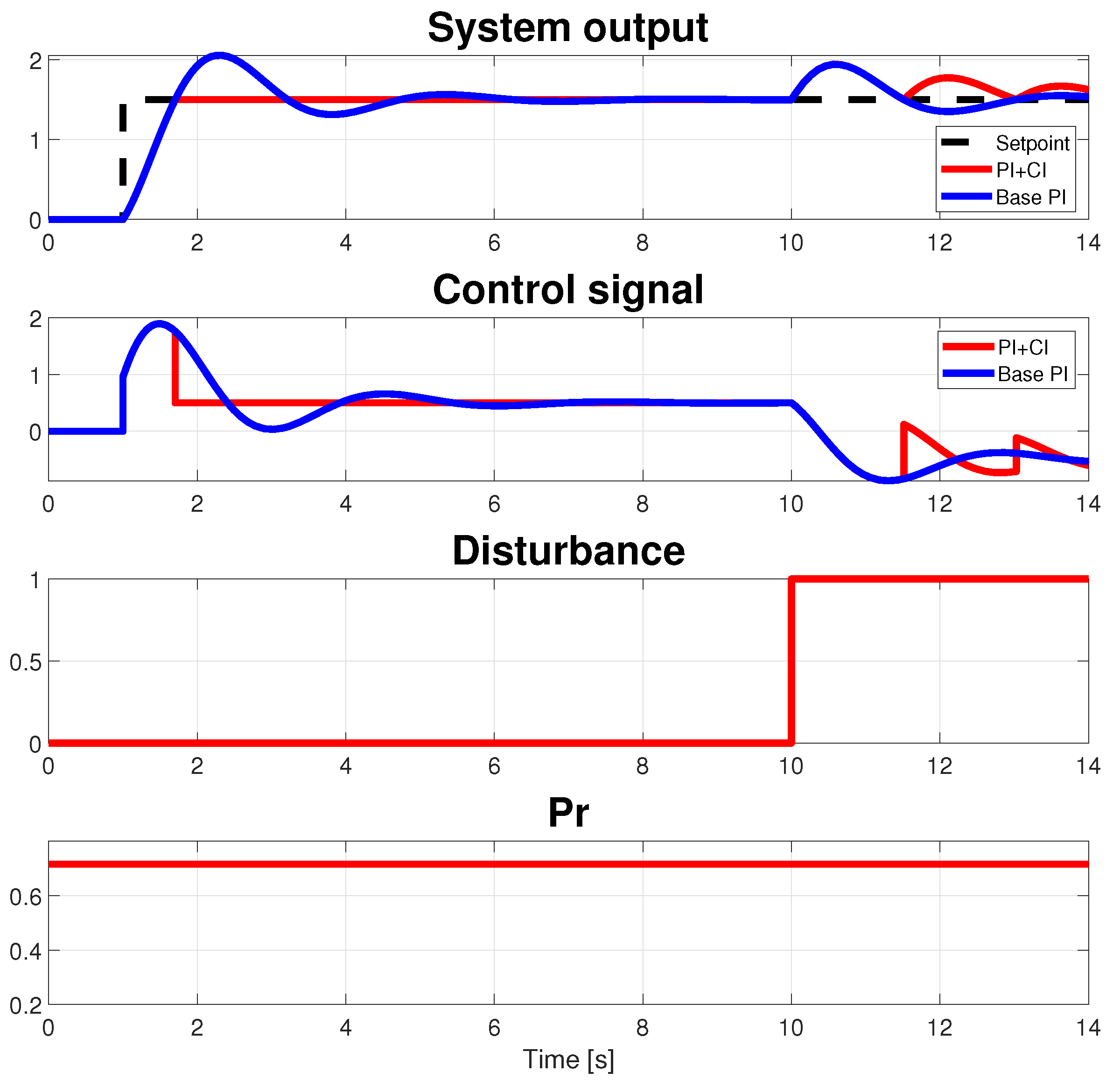
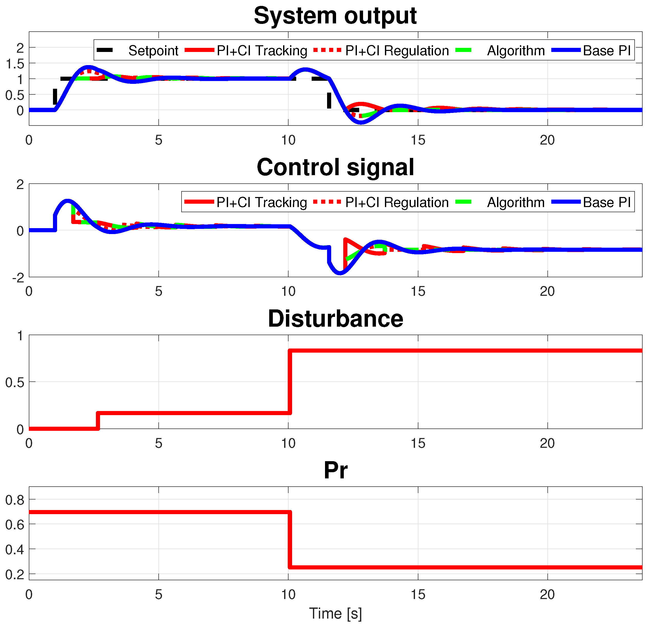
Assuming the specifications given by a damping factor ξ = 0.33 and the undamped natural frequency ω n = 2.21 rad/s ( t p = 1.51 s), in the first study case, the process is given by Equation (9). The base PI is given by k p = 0.64 and τ i = 0.20 (s). The value of the reset ratio to ensure the minimum IAE would be p r = 0.71 according to Equation (12). Figure 15 shows the response for this configuration, where a setpoint change of 1.5 and a disturbance with amplitude of 1 are introduced at times t = 1 and t = 10 (s), respectively. As shown, the performance for PI+CI is better (IAE of 1.3489) than for PI (IAE of 1.9109), but it is not possible to achieve a flat response taking into account simultaneously both tracking and regulation problems, as expected.
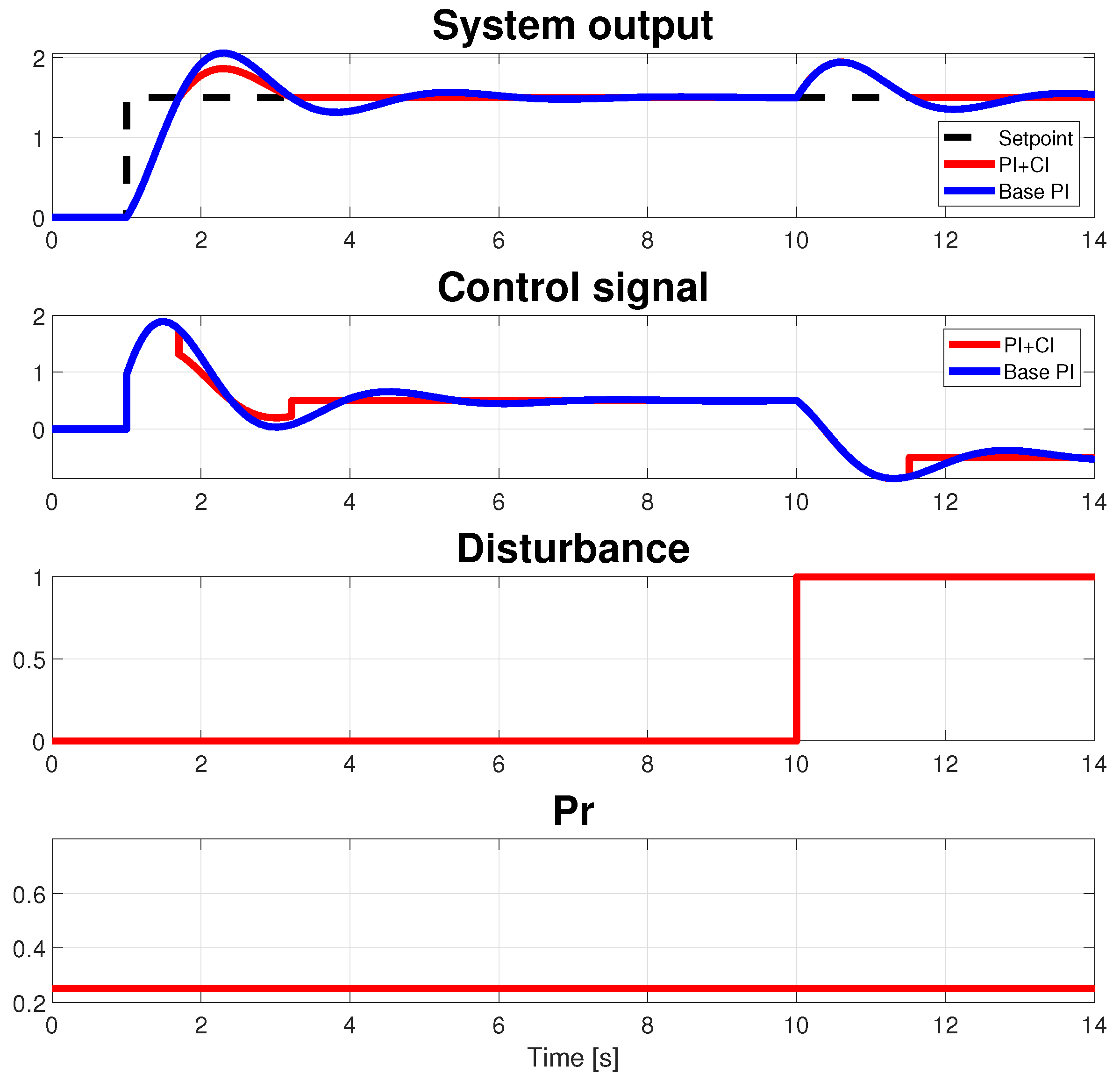
Now, when the value p r is set from Equation (14) and used for both regulation and tracking problems, the results in Figure 16 are obtained (IAE 1.292). As observed, the response to the regulation problem is flat after the first reset time, as expected, but in the case of the tracking problem, the response is not flat until the second reset time, obtaining worse results, in the first part of the simulation, than those in Figure 15. If the algorithm proposed in the previous section is used, the results in Figure 17 are obtained. As observed, a flat response is obtained after the first reset time for both tracking and regulation problems, as expected, resulting in an IAE of 0.9846.
Now, several simulations are performed to validate the algorithm, controlling systems with different combinations of values for the gain and the time constant. Ten cases are considered with the gain and/or time constant outside the range [1, 10] considered in Section 3. Four controllers are compared: a PI+CI with preset from Equation (12) (PI+CI Tracking), a PI+CI with a preset from Equation (14) (PI+CI Regulation), the base PI, and the proposed control algorithm. Two scenarios are considered. In Table 1, the results are provided for a test, Scenario 1, where a reference of amplitude A r = 1 is inserted at time t = 1 (s) and a disturbance with amplitude A d = 1 is added in steady state at time t = 5 t p + 1 (setpoint change and disturbance arriving in steady state). Note that the time to add the disturbance depends on each particular system ( t p = n τ ). In all cases, the control algorithm provides the best results. Table 2 shows the results for scenario 2, where an amplitude change of setpoint of A r = 1 is introduced at time t = 1 (s), a disturbance of amplitude A d = A r / ( 2 k ) is inserted at time t = 1.1 t p + 1 (s), between the first and second reset time after the change of setpoint, a second disturbance of A d = 2 A r / k is added at t = 6 t p + 1 (s), and a second change of setpoint with amplitude A r = 1 is introduced at t = 7 t p + 1 (s) before achieving steady state after the second disturbance. In all cases, the control algorithm shows the best IAE. To visualize the scenarios used for the simulations, Figure 17 shows a simulation for scenario 1 (but using A r = 1.5 ), and Figure 18 shows a simulation for scenario 2, which is used to calculate Table 1 and Table 2, respectively, where the system is given by Equation (9). In this case, IAE values of 1.5577, 1.4234, 1.3024, and 2.0344, respectively, are obtained for the four controllers previously mentioned.

5. An Example

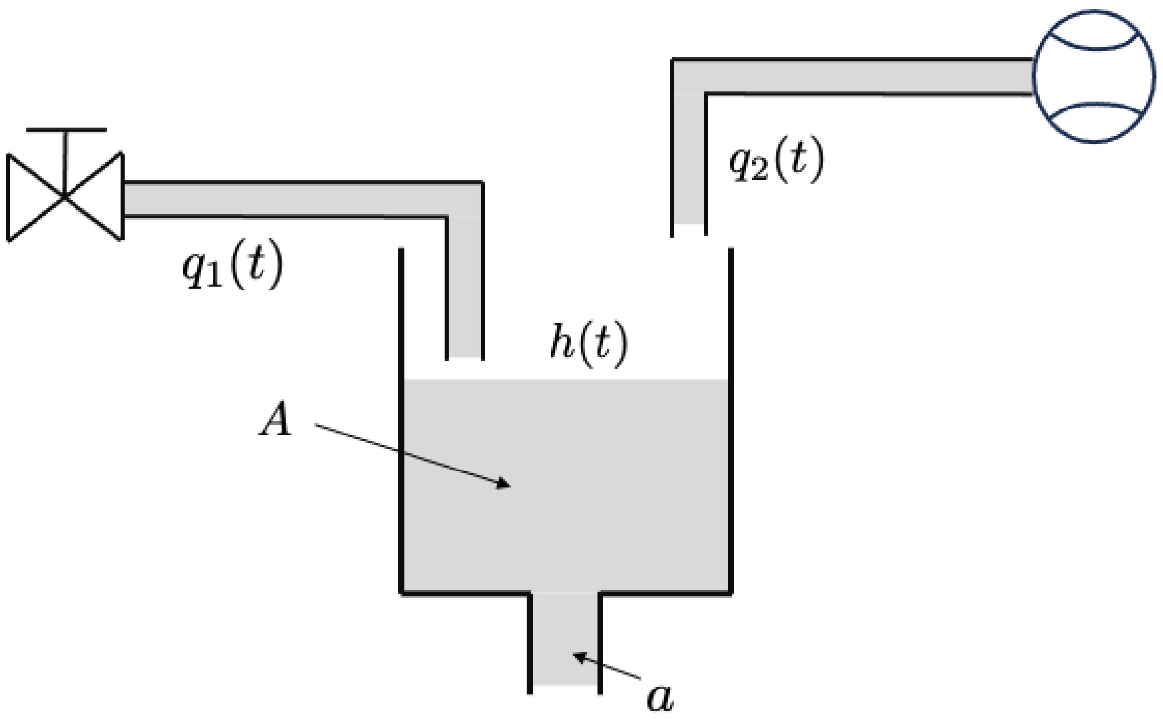
In this section, the previous rules are tested using a fluid flow reservoir (Figure 19). We assume that the water in the tank is incompressible and the flow is inviscid, irrotational, and steady and the mathematical nonlinear model, derived from basic principles of science and engineering [25] is given by:
A h ˙ ( t ) = q 1 ( t ) a 2 g h ( t ) + q 2 ( t )
where A is the tank area, ρ is the density of water, a is the output port area, h ( t ) is the height of the water in the reservoir, g is the gravity constant, q 1 ( t ) is the input mass flow rate and q 2 ( t ) is a measurable disturbance of the mass flow rate. This nonlinear system can be approximated by a linear system using Taylor series expansion about an equilibrium flow condition and neglecting the higher-order terms. When the tank system is in equilibrium, h ˙ ( t ) = 0 , thus defining q 1 * and h * as the equilibrium mass flow rate and the water level, respectively, and
h ( t ) = h * + Δ h q 1 ( t ) = q 1 * + Δ q 1
the linear approximation is given by the following:
Δ h ˙ ( t ) = a 2 g ρ A q 1 * Δ h ( t ) + 1 ρ A Δ q 1 ( t )
where Δ h is the deviation in the water level from the operating point due to a deviation from the nominal input mass flow rate Δ q 1 . Assuming A = 840 (cm2), a = 2 (cm2), g = 981 (cm/s2), h * = 5 (cm), and q 1 * = 198.09 (cm3/s), the following transfer function is obtained:
Δ H ( s ) Δ Q ( s ) = 0.0505 42.4048 s + 1
Assuming the closed-loop specifications given by a damping factor ξ = 0.33 and the undamped natural frequency ω n = 0.1570 (rad/s) ( t p = 21.2024 (s), that is, n = 0.5 ), the base PI is given by k p = 67.2121 (cm3/s/cm) and τ i = 3.2476 (s). The simulation scenario is given by a first positive change in the set point of A r = 1 (cm) at t = 10 (s), which is followed by a second change in the setpoint at t = 10 + 5 t p (s) with a value of A r = 1 (cm). Subsequently, when the system is in steady state, a disturbance is applied at t = 10 + 10 t p (s) with A d = 80 (cm3/s), which is followed by another disturbance at t = 10 + 15 t p (s) with A d = 50 (cm3/s). Finally, a new change in the setpoint is applied with A r = 1 (cm) before achieving steady state at t = 10 + 15.5 t p (s). The results obtained using the model described by Equation (16) for the system are shown in Figure 20. Note that in t = 0 (s), the control signal q 1 ( t ) = q 1 * and the signal output h ( t ) = h * , because the approximation is only valid at the chosen operation point. As shown, the supervisor in Figure 11 following the proposed control algorithm allows one to obtain a much better response vs. the base PI with an IAE of 26.736 vs. the IAE of 51.525 obtained for the PI. Notice that in this simulation, the nonlinear model described in (16) was used as a plant, demonstrating that the performance of the proposed approach works with nonlinear systems around a given operating point.

6. Conclusions and Future Work

This paper proposes an algorithm based on simple tuning rules for the PI+CI controller, for both tracking and regulation problems, assuming first-order dynamics for the plant. These rules assure optimal performance in terms of the Integral Absolute Error (IAE) and, in contrast to those already existing in the literature, depend only on the closed-loop specifications. Furthermore, the proposed control algorithm makes it possible to consider for the first time the tracking and regulation problems simultaneously, i.e., cases where setpoint changes and disturbance arrivals can occur at the same time before reaching a new steady state. So, this work shows that the minimum IAE criterion is an adequate tool for design purposes. The proposed rules can also be applied to higher-order systems when they can be approximated by first-order models. The main limitation and, at the same time, the main advantage of these rules is given by the method used to obtain them. The numerical method provides a solution close to the optimum theoretical results obtained in the literature but being more practical and generalizable to more complex problems. Moreover, note that this method only ensures the best behavior when measurable step-like disturbances are considered. In future work, this idea will be extended to cope with first-order systems with dead time using a variable reset ratio and a variable reset band.

Author Contributions

Conceptualization and methodology, J.L.G. and J.C.M.; software, A.N. and J.G.; validation and writing, J.L.G., J.C.M. and J.G.; supervision and funding acquisition, J.L.G. and J.C.M. All authors have read and agreed to the published version of the manuscript.

Funding

This research was supported by PID2020-112709RB-C21 (financed by the Spanish Ministry of Science and Innovation and EU-ERDF funds). The APC was funded by PID2020-112709RB-C21.

Data Availability Statement

No new data were created or analyzed in this study. Data sharing is not applicable to this article.

Conflicts of Interest

The authors declare no conflicts of interest.

References

  1. Clegg, J.C. A nonlinear integrator for servomechanisms. Trans. Am. Inst. Electr. Eng. Part II Appl. Ind. 1958, 77, 41–42. [Google Scholar] [CrossRef]
  2. Horowitz, I.; Rosenbaum, P. Non-linear design for cost of feedback reduction in systems with large parameter uncertainty. Int. J. Control 1975, 21, 977–1001. [Google Scholar] [CrossRef]
  3. Krishnan, K.R.; Horowitz, I.M. Synthesis of a non-linear feedback system with significant plant-ignorance for prescribed system tolerances†. Int. J. Control 1974, 19, 689–706. [Google Scholar] [CrossRef]
  4. Bainov, D.D.; Simeonov, P.S. Systems with Impulse Effect: Stability, Theory, and Applications; Ellis Horwood Series in Mathematics and Its Applications; Wiley Online Library: Hoboken, NJ, USA, 1989; p. 255. [Google Scholar]
  5. Sáez, J.F. Reset Control of Multiple-Input Single-Output Systems. Ph.D. Thesis, University of Murcia, Murcia, Spain, 2023. [Google Scholar]
  6. Baños, A.; Barreiro, A. Reset Control Systems; Springer: London, UK, 2012. [Google Scholar] [CrossRef]
  7. Åström, K.J.; Hägglund, T. The future of PID control. Control Eng. Pract. 2001, 9, 1163–1175. [Google Scholar] [CrossRef]
  8. Beker, O. Analysis of Reset Control Systems. Ph.D. Thesis, University of Massachusetts, Amherst, MA, USA, 2001. [Google Scholar]
  9. Vidal, A.; Baños, A. Reset compensation for temperature control: Experimental application on heat exchangers. Chem. Eng. J. 2010, 159, 170–181. [Google Scholar] [CrossRef]
  10. Davó, M.A.; Baños, A. Delay-dependent stability of reset control systems with input/output delays. In Proceedings of the 52nd IEEE Conference on Decision and Control, Firenze, Italy, 10–13 December 2013; pp. 2018–2023. [Google Scholar]
  11. Nair, U.R.; Costa-Castelló, R.; Baños, A. Grid voltage regulation using a reset PI+CI controller for Energy storage systems. IFAC-PapersOnLine 2018, 51, 226–231. [Google Scholar] [CrossRef]
  12. Mulero-Martínez, J.I.; Baños, A.; Moreno, J.C.; Guzmán, J.L. Hybrid Controller for an Industrial Raceway Photobioreactor. In Proceedings of the 2023 IEEE 28th International Conference on Emerging Technologies and Factory Automation (ETFA), Sinaia, Romania, 12–15 September 2023. [Google Scholar] [CrossRef]
  13. Baños, A.; Vidal, A. Design of reset control systems: The PI+CI compensator. J. Dyn. Syst. Meas. Control. Trans. ASME 2012, 134, 051003. [Google Scholar] [CrossRef]
  14. Joraked, S.; Pongyart, W.; Angkeaw, K. Design and implementation of a FPAA based PI+CI reset controller Emulator. In Proceedings of the ISCIT 2018—18th International Symposium on Communication and Information Technology, Bangkok, Thailand, 26–29 September 2018; pp. 408–411. [Google Scholar] [CrossRef]
  15. Doktian, J.; Pongyart, W.; Vanichchanunt, P. Development of a Semi Auto-Tuning Algorithm for PI+CI Reset Controller. In Proceedings of the 2019 1st International Symposium on Instrumentation, Control, Artificial Intelligence, and Robotics, ICA-SYMP 2019, Bangkok, Thailand, 16–18 January 2019; pp. 155–158. [Google Scholar] [CrossRef]
  16. Banki, T.; Faghihi, F.; Soleymani, S. Robust Frequency Control of Provisional Microgrid by Using of a Combined Fuzzy Reset Approach. J. Electr. Eng. Technol. 2023, 19, 125–132. [Google Scholar] [CrossRef]
  17. Shakibjoo, A.D.; Vasegh, N. Method for Analytically Obtaining Reset Ratio in Non-Minimum Phase Systems with PI+CI Controller in order to Improve Performance. Int. J. Mechatronics Electr. Comput. Technol. 2014, 4, 1880–1899. [Google Scholar]
  18. Baños, A.; Davó, M.A. Tuning of reset proportional integral compensators with a variable reset ratio and reset band. IET Control Theory Appl. 2014, 8, 1949–1962. [Google Scholar] [CrossRef]
  19. Bakkeheim, J.; Smogeli, O.N.; Johansen, T.A.; Sorensen, A.J. Improved transient performance by lyapunov-based integrator reset of PI thruster control in extreme seas. In Proceedings of the IEEE Conference on Decision and Control, San Diego, CA, USA, 13–15 December 2006; pp. 4052–4057. [Google Scholar] [CrossRef]
  20. Wu, D.; Guo, G.; Wang, Y. Reset integral-derivative control for HDD servo systems. IEEE Trans. Control Syst. Technol. 2007, 15, 161–167. [Google Scholar] [CrossRef]
  21. Aangenent, W.H.; Witvoet, G.; Heemels, W.P.; Van De Molengraft, M.J.; Steinbuch, M. Performance analysis of reset control systems. Int. J. Robust Nonlinear Control 2010, 20, 1213–1233. [Google Scholar] [CrossRef]
  22. Nešić, D.; Zaccarian, L.; Teel, A.R. Stability properties of reset systems. Automatica 2008, 44, 2019–2026. [Google Scholar] [CrossRef]
  23. Nešić, D.; Teel, A.R.; Zaccarian, L. On necessary and sufficient conditions for exponential and L2 stability of planar reset systems. In Proceedings of the 2008 American Control Conference, Seattle, WA, USA, 11–13 June 2008; pp. 4140–4145. [Google Scholar] [CrossRef]
  24. Åström, K.; Hägglund, T. Advanced PID Control; ISA—The Instrumentation, Systems and Automation Society: Research Triangle Park, NC, USA, 2006. [Google Scholar]
  25. Dorf, R.; Bishop, R. Modern Control Systems, 12th ed.; Pearson: Upper Saddle River, NJ, USA, 2010. [Google Scholar]
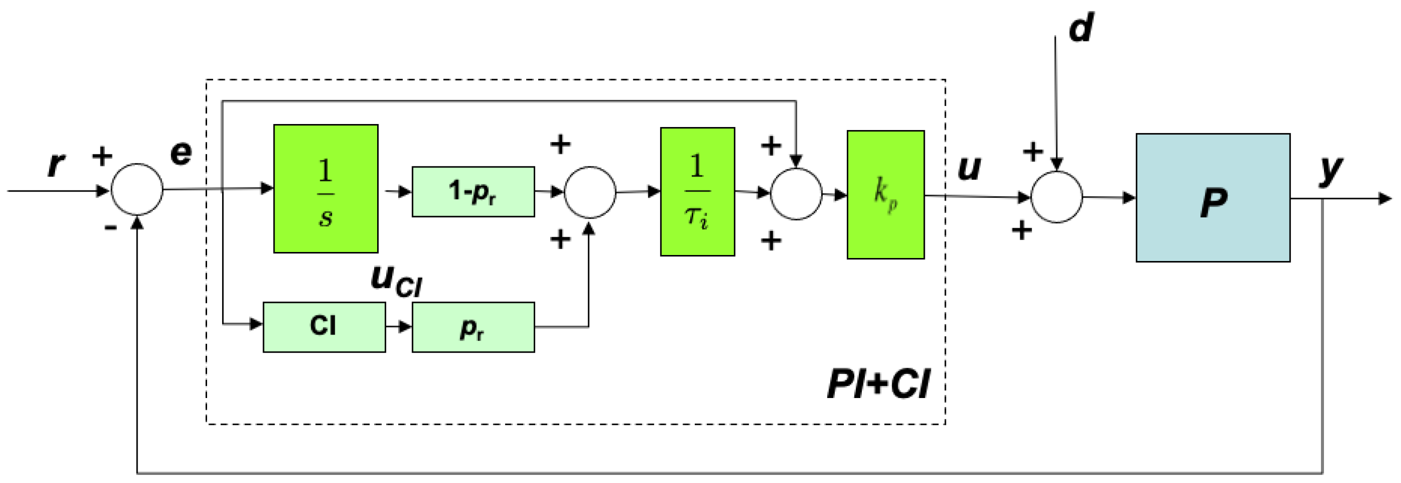
Figure 1. Closed−loop control scheme using a PI+CI nonlinear controller.
Actuators 13 00067 g001
Figure 2. Performance comparison between PI and PI+CI controllers for p r from Equation (5).
Actuators 13 00067 g002
Figure 3. Performance comparison between PI and PI+CI controllers for p r from Equation (8).
Actuators 13 00067 g003
Figure 4. Sweep of p r and second-order polynomial fitting for the tracking problem.
Actuators 13 00067 g004
Figure 5. Fitting of p r as a fifth-order polynomial function of τ .
Actuators 13 00067 g005
Figure 6. Fitting of p r as the exponential function of τ in Equation (11).
Actuators 13 00067 g006
Figure 7. Sweep and fitting of p r as a polynomial of n and ξ specifications.
Actuators 13 00067 g007
Figure 8. Performance for a representative set of plants using p r = 0.25 for the regulation problem.
Actuators 13 00067 g008
Figure 9. Fitting of p r as a third-order polynomial of specifications n and ξ .
Actuators 13 00067 g009
Figure 10. Optimum p r for tracking (upper) and regulation (lower) problems.
Actuators 13 00067 g010
Figure 11. Reset switching control scheme.
Actuators 13 00067 g011
Figure 12. Switching control performance for the proposed scenario with p r from Equation (12).
Actuators 13 00067 g012
Figure 13. Switching control performance for the proposed scenario with p r from Equation (14).
Actuators 13 00067 g013
Figure 14. Switching control performance for the proposed scenario, with p r from Equation (14) and (12), for a plant with small static gain.
Actuators 13 00067 g014
Figure 15. Performance comparison between PI and PI+CI controllers for p r from Equation (12).
Actuators 13 00067 g015
Figure 16. Performance comparison between PI and PI+CI controllers for p r from Equation (14).
Actuators 13 00067 g016
Figure 17. Performance comparison between PI and the switching controller.
Actuators 13 00067 g017
Figure 18. Performance comparison for scenario 2 and system given by Equation (9).
Actuators 13 00067 g018
Figure 19. The fluid flow reservoir configuration.
Actuators 13 00067 g019
Figure 20. Level control for a fluid tank using the proposed solution vs. a classical PI.
Actuators 13 00067 g020
Table 1. Comparison in terms of IAE between four controllers for different systems in simulations assuming changes in disturbance and setpoint occuring at steady state.
PlantPI+CI TrackingPI+CI RegulationAlgorithmBase PI
k = 20 τ = 30 107.8654.4451.25881.861
k = 30 τ = 20 104.9850.04648.15675.231
k = 0.1 τ = 20 6.08528.92675.851813.424
k = 20 τ = 0.1 0.35950.181460.166090.27284
k = 0.1 τ = 0.5 0.152120.223190.146340.335759
k = 0.5 τ = 0.1 0.0370440.0473960.0320190.0713055
k = 5 τ = 0.1 0.111450.0783240.063040.1178
k = 0.1 τ = 5 1.52132.23191.4633.3584
k = 20 τ = 5 17.9769.07338.34413.642
k = 5 τ = 20 22.29315.66512.58923.569
Table 2. Comparison in terms of IAE between four controllers for different systems in simulations mixing disturbance and setpoint change occuring at non-steady state.
PlantPI+CI TrackingPI+CI RegulationAlgorithm 1Base PI
k = 20 τ = 30 23.45521.35519.48530.551
k = 30 τ = 20 15.63714.23613.0420.325
k = 0.1 τ = 20 15.63414.23513.05320.36
k = 20 τ = 0.1 0.0781880.0711760.0651030.10183
k = 0.1 τ = 0.5 0.390870.355890.326110.50932
k = 0.5 τ = 0.1 0.0781630.0711730.0652530.10182
k = 5 τ = 0.1 0.0781620.0711730.0652170.10169
k = 0.1 τ = 5 3.90773.55893.26275.0921
k = 20 τ = 5 3.90923.55923.23545.0909
k = 5 τ = 20 15.63814.23612.99120.365
Disclaimer/Publisher’s Note: The statements, opinions and data contained in all publications are solely those of the individual author(s) and contributor(s) and not of MDPI and/or the editor(s). MDPI and/or the editor(s) disclaim responsibility for any injury to people or property resulting from any ideas, methods, instructions or products referred to in the content.