Article

Computational Control Strategy for Reducing Medial Compartment Load in Knee Bracing with Embedded Actuator

by
Mahdi Bamdad
1,2,* and
Amirhosein Javanfar
1
1
Corrective Exercise and Rehabilitation Laboratory, School of Mechanical and Mechatronics Engineering, Shahrood 3619995161, Iran
2
Department of Health Science and Technology, Aalborg University, 9220 Aalborg, Denmark
*
Author to whom correspondence should be addressed.
Actuators 2023, 12(6), 256; https://doi.org/10.3390/act12060256
Submission received: 22 May 2023 / Revised: 13 June 2023 / Accepted: 17 June 2023 / Published: 19 June 2023
(This article belongs to the Special Issue Actuators in Assistive and Rehabilitation Robotics)

Abstract

:
Medial unloader braces represent a primary noninvasive approach for alleviating knee pain. However, conventional valgus unloader braces, while reducing load on the medial compartment, inadvertently increase load on the lateral compartment through rotation from adduction to abduction. This phenomenon significantly elevates the risk of damage to the lateral compartment. To address this issue, we introduce a novel embedded actuation mechanism that unloads the knee using a pioneering computational procedure. By considering the knee osteoarthritis condition, we propose the calculation of the adduction knee angle and cartilage penetration depth as surrogate parameters for assessing knee pain. Accordingly, the newly developed unloader brace redistributes the load by precisely correcting the abduction angle. Additionally, we determine the maximum required torque for effectively tracking the desired abduction angle. Then, the saturated torque through the robust control method is applied in the presence of interaction force uncertainty between the orthosis and the user. A very small femur rotation change (1.7°) from adduction to abduction in the frontal plane is adequate to significantly reduce the medial contact force (around 886 N). The required robust external abduction torque is determined to be 27.6 Nm. The result shows that the novel procedure and brace prevent excessive overloading of the lateral compartment while it unloads the medial compartment sufficiently. This innovative approach offers significant potential for optimizing unloader brace design and enhancing the management of knee osteoarthritis.

1. Introduction

Osteoarthritis (OA) is the most prevalent disorder affecting the tibiofemoral joint, leading to the narrowing of the joint space [1]. Medial compartment OA accounts for the majority of OA cases [2]. It is essential to reduce knee load based on biomechanical and clinical considerations [3]. Various noninvasive techniques, including valgus braces, canes or shoe soles, and gait modifications, have been employed to mitigate medial contact force (MCF) [4,5]. The role of the lower limb is crucial in delaying the progression of knee osteoarthritis (KOA) [6,7]. Mechanical factors such as contact point, range of motion, and contact force represent key parameters that require evaluation [8].
Knee bracing may reduce pain and disease progression, thereby postponing the need for joint replacement [9] by unloading the internal knee contact forces (CF) in the affected area via applying external loads and moments [10]. There are three primary mechanisms through which a knee brace might unload the medial condyle: direct application of an external brace abduction moment, altered gait dynamics, or modified muscle activation [11]. As a noninvasive treatment of KOA, the predominant focus is on the reduction of the external knee adduction moment (KAM) [9,10,11,12,13]. KAM is often considered a surrogate measure of the medial CF [14,15,16].
Walter et al. observed that simply reducing knee adduction moment (KAM) in vivo may not necessarily lead to a reduction in the internal loads on the medial compartment [15]. Furthermore, the presence of medial thrust gait inhibits the increase of KAM by elevating the knee flexion moment (KFM) [15], and KFM has a significant impact on the initial peak of contact force (CF) [16]. Consequently, exoskeletons have been developed to actively [17,18,19] or passively [20,21] provide knee flexion moment (KFM) to alleviate CF. Therefore, simultaneous attention to KFM and KAM is essential in supporting arthritic knees.
Offloader knee braces alter knee orientation in the frontal plane by exerting force through adjustable straps [22]. However, active provision of KAM is lacking in such braces. The Levitation brace (Springloaded Technology, Halifax, NS, Canada) additionally unloads the medial compartment through a three-point offloader mechanism [23]. However, this unloading can result in the overloading of the lateral compartment [24]. A subsequent experimental study [25] concludes that a higher valgus alignment angle increases the risk of damage to the lateral compartment. Interestingly, this phenomenon is disregarded in another study [26]. Therefore, it is imperative to introduce an active unloader knee brace integrated with a robotic control system to modulate the knee adduction angle (KAA).
To the best of our knowledge, the control of knee adduction angle and forward dynamic simulation in the frontal plane were not attempted to distribute joint reaction force between the medial and lateral condyle.
Specifically, no study has investigated the robust abduction torque required due to the uncertainty of the interaction force between the orthosis and the user. Our proposed innovative computational procedure calculates the desired adduction angle and streamlines the protecting process of the KOA with the unloader brace. In summary, the contributions of this paper can be outlined as follows, in a stepwise manner:
  • Step 1: We present an efficient unloading strategy based on penetration depth reduction to avoid lateral compartment overloading along with adequate medial compartment unloading.
  • Step 2: We calculate robust abduction torque to alter the adduction angle in the presence of interaction force uncertainty between the orthosis and the user.
  • Step 3: We design the embedded actuator hinge for the knee brace to control the adduction angle.
  • Step 4: The nonlinear position controller design according to a robust inverse dynamic method adjusts the abduction torque to track the desired adduction angle.
The subsequent sections of the work are organized as follows: Section 2 covers the related work, hypothesis, problem statement, knee joint model, and dynamic and control modeling. Section 3 presents the results and simulation outcomes. Section 4 provides a detailed discussion, and Section 5 concludes the paper.

2. Materials and Methods

2.1. Related Work

This section includes the most relevant studies and highlights their main findings and contributions, as well as any gaps that the current study aims to fill. Therefore, paying attention to the studies on (1) brace design and control and (2) knee modeling is critical. One major gap in the existing literature lies in addressing the interconnection between these objectives. The relationship between topics (1) and (2) will enhance the effectiveness of braces in supporting arthritic knees.
In the context of brace design and control, previous studies focus on applying active torque only during the stance phase in the frontal plane, aligning with the concept of active unloading [27]. Additionally, in the area of knee modeling, the studies aim to quantitatively assess the impact of the applied brace abduction moment, gait dynamics, and muscle activation [25,28]. These endeavors contribute to filling the existing gaps and improving the performance of knee braces in the management of arthritic knees.
The studies [28,29] concluded that reducing medial knee loads is not simply achieved by applying an external brace moment, but also by inducing changes in both gait dynamics such as abduction angle [29] and neuromuscular control [28]. Regarding the influence of braces, studies [25,28] present the reduction of medial loads during gait, using a detailed musculoskeletal model with a knee multibody model [28], and experimentally measuring forces and moments with a three-dimensional finite element model [25]. The limitations identified in [28] include the lack of accuracy in knee modeling and the neglect of viscoelastic behavior and cartilage penetration depth. In [25], although the model demonstrates high accuracy, the computational time of finite element methods becomes a barrier to timely performance and real-time knee behavior correction by the brace control processes. Figure 1 illustrates various types of exoskeletons and knee braces that were designed to control the knee joint. The effectiveness of unloader knee braces is evident based on previous research studies. However, the discussion on their limitations is still ongoing. Since it is currently not easy to directly measure in vivo loads in a native knee, the relationship between abduction torque, adduction angle, and contact loads is not well established. Therefore, our research aims to focus on precisely understanding and quantifying this link through a computational approach. In addition to the mentioned limitations, previous studies such as [25,28] have focused on investigating the individual contributions of these factors without specifically calculating the required torque to achieve the desired abduction angle, which is crucial for effectively distributing the joint reaction force.
When a patient utilizes an orthosis, it is essential to employ an appropriate knee model [30,31] to accurately control the mechanical parameters of the knee. While there have been recent studies on the control and forward dynamic simulation of musculoskeletal models in combination with exoskeletons [32,33,34], the focus on motion control has been limited [32], and the consideration of the knee in the frontal plane has been overlooked [33,34]. Furthermore, while studies [32,33,34] have considered the interaction force between the orthosis and the user, they have not accounted for the uncertainty associated with this force. This is a limitation in terms of the third objective of the present study.

2.2. Hypothesis

The hypothesis is that the proposed embedded actuation mechanism and computational procedure in the design of the unloader brace can effectively address the issues of medial compartment overload and lateral compartment damage in knee osteoarthritis (KOA). The hypothesis is based on the following key points:
  • Medial unloader braces, although commonly used for KOA, can lead to lateral overloading due to neglecting the phenomenon of unwarranted rotation from adduction to abduction.
  • The new embedded actuation mechanism in the proposed unloader brace aims to correct the knee adduction angle (KAA) actively, thereby addressing the issue of lateral compartment overload.
  • The computational procedure used in the design of the brace takes into account factors such as cartilage penetration depth, contact force, and contact point, which are surrogate parameters for determining pain and damage in KOA.
  • Through simulation and analysis, it is hypothesized that by controlling the KAA and applying external abduction torque, the proposed unloader brace can effectively reduce medial compartment load and prevent excessive lateral compartment loading.

2.3. Problem Statement

The medial and lateral distribution of joint reaction force is calculated by applying force and moment equilibrium in the frontal plane [35]. The contact point is crucial in assessing the medial and lateral compartment moment arm [30] to distribute the joint reaction force. The peak net knee adduction moment progressively decreased with increasing valgus alignment of the knee brace [36]. In addition, we know that the partitioning of knee joint internal forces in gait is dictated by the knee adduction angle and not by the knee adduction moment [29].
This study revealed that controlling the designed actuation had a significant impact on the knee joint, indicating the need for careful consideration of the brace’s design. Analyzing the biomechanics of gait [37], contact deformation is instrumental in understanding joint degeneration and function in vivo cartilage studies [38] such as cartilage indentation presented during the gait cycle [39]. Preventing bone–bone contact, the desired cartilage penetration depth is determined in sagittal plane when a healthy subject (75.16 kg, 1.8 m tall) walks at 1.0 m/s.
In this study, our proposed relation calculates the desired knee adduction angle. The robust abduction torque assists the knee to track the desired abduction–adduction angle in the presence of interaction force uncertainty for the first time. Moreover, to achieve the goal, the double hinge is designed to create the degree of freedom (DOF) in the direction. The following sections clarify how the novel knee brace design assists us with knee unloading. Then the knee motion is controlled in frontal plane similar to our previous research [40] (with a more detailed description and further design details).
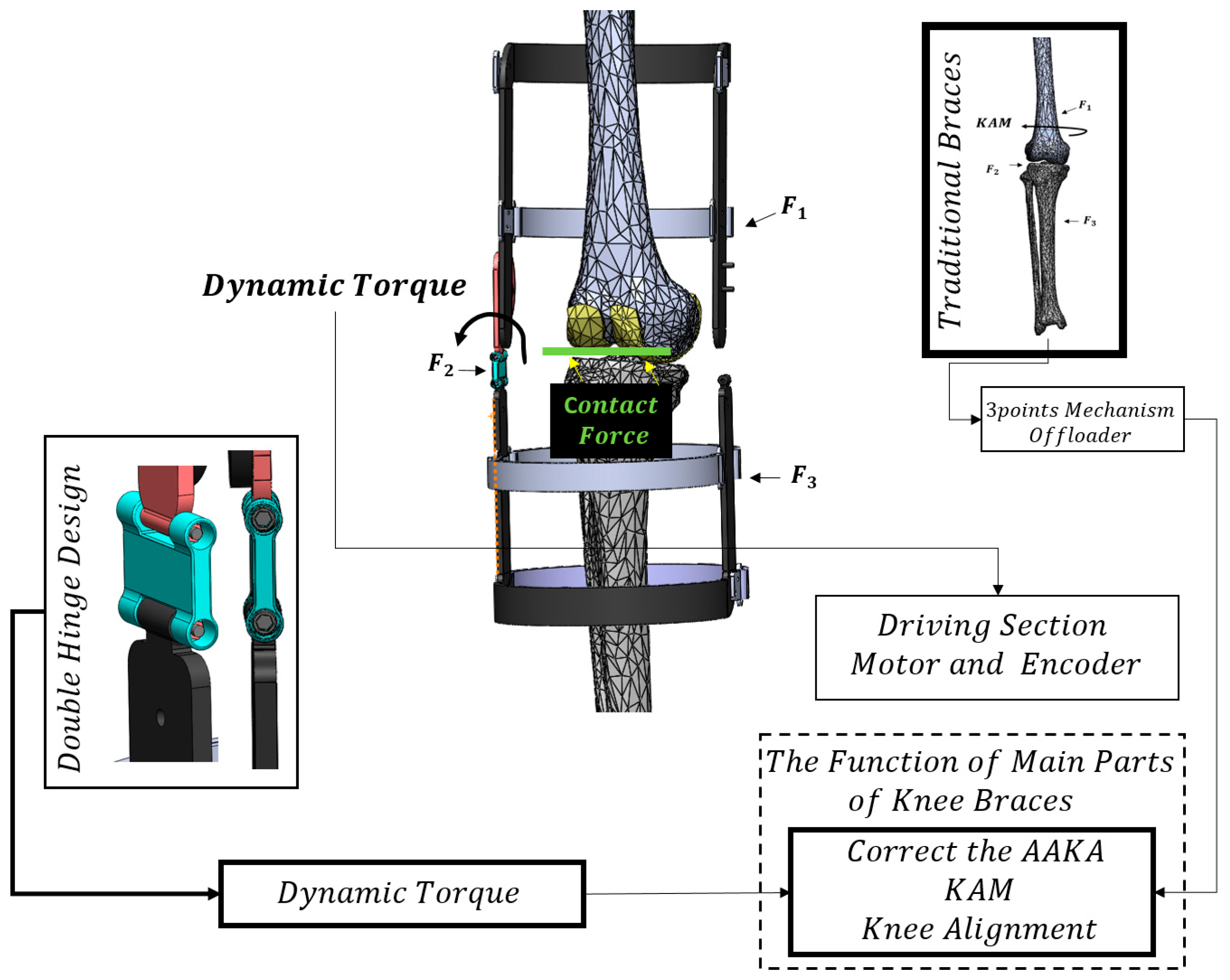
Figure 2 presents our brace featuring a double hinge design aimed at correcting the knee adduction angle (KAA). To facilitate KAA control, we incorporated an actuation mechanism into the brace, allowing for the application of dynamic abduction torque. In contrast, the levitation brace [23] utilizes a three-point mechanism offloader. Traditional braces as shown in Figure 1, do not offer adjustable abduction torque. However, our novel brace actively controls KAA by providing variable abduction torque, thereby enhancing the reliability of the medial compartment unloading system and mitigating the risk of lateral overloading.
The proposed design not only incorporates features found in the levitation brace, such as support for the center of rotation (COR), knee flexion moment (KFM) via the levitation flexion hinge, and joint reaction force through a liquid compression spring but also introduces a dynamic abduction torque component. This dynamic torque is specifically applied to correct the knee adduction angle (KAA). Unlike previous studies [23,41] that resulted in undesired overloading of the lateral compartment, our novel computational procedure takes into account the KAA, medial contact force (MCF), and lateral compartment overloading to determine the desired KAA and the necessary external robust abduction torque. As a result, this approach enhances the safety of the interaction.
In this proof-of-concept study, knee geometry is defined using MR images from MIMICS software (Materialise Group, Leuven, Belgium). The knee geometry and the designed brace are integrated using SolidWorks 2016 software (Dassault Systèmes, Vélizy-Villacoublay, France). The motion study feature is employed to verify the dimensions and functionality of the brace. Inspired by a previous study [42] that introduced a double hinge mechanism to correct valgus alignment angles, our present study incorporates an embedded actuation double hinge between the lower and upper cuff to actively modify the KAA. This actuation control allows for logical load distribution and prevents lateral overload.
The primary design concept revolves around the implementation of the double-hinge actuation mechanism for correcting the KAA [42]. During walking, the knee typically exhibits up to 4 degrees of adduction and 4 degrees of abduction [43]. By incorporating the double-hinge mechanism, our design can effectively address this degree of freedom in the frontal plane of the knee, while previous braces [23] typically lack this capability. The double-hinge mechanism and a driven rotary motor are integrated into the brace to control the KAA effectively. One of the most requisite processes in KOA bracing is the relation between mechanical parameters, particularly KAA and CF. Noticeably, it is very crucial that the unloading of the medial compartment is correlated with lateral overload. Therefore, characterizing the parameters contributing to the medial contact force can potentially help find more effective therapeutic interventions to slow down progression.

2.4. Knee Joint Model

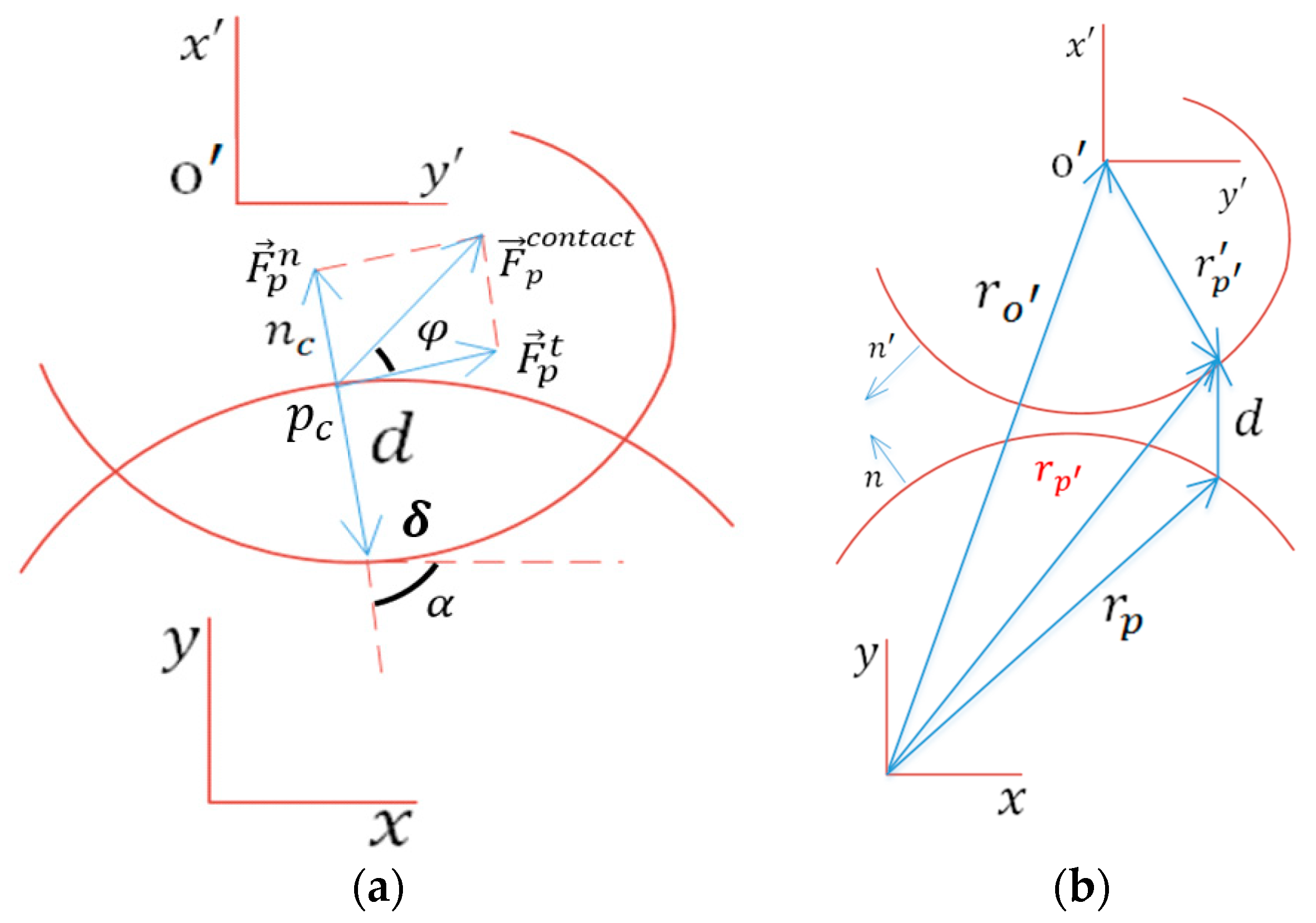
We incorporate the measurement of cartilage penetration depth, denoted as δ = n T d , as a means to establish a relationship between the unloading of the medial compartment and the potential overloading of the lateral compartment. This correlation allows us to assess the impact of medial compartment unloading on the loading conditions experienced by the lateral compartment. As shown in Figure 3 and Figure 4, it is necessary to make a relation between lateral δ, medial δ, and KAA. Therefore, the equation of motion according to the Multibody system dynamic attitude is used to achieve the knee mechanical parameters. This is the first study that presents the equation which states the correlation of KAA, MCF, and LCF with δ shown in Figure 4 to calculate MCF and LCF, according to our previous research [39]. Due to calculating optimal KAA, parameters δ and MCF are required. Therefore, MCF calculation is performed through modeling in the sagittal plane, as shown in Figure 3. The distance vector d connects two points of potential contact p , p as d = r p r p . In the global coordinate system, considering the inertial reference frame, we have
r p = r o + A k r p
where A k is the rotation matrix and the r p is a vector in the local coordinate system. Furthermore, p c is the point of maximum penetration depth in collision geometrical conditions [39].
Then, δ on p c is used in our proposed model based on the concept of viscoelastic two-layer collision modeling, which can be recast as follows [39]:
F T N = K 1 δ n + B c ( δ ) δ ˙ i f δ h s 1 K 1 h s 1 n + K 2 δ h s 1 n + B c ( δ ) δ ˙ i f δ > h s 1
where K is the general stiffnesses and B c ( δ ) , K 1 , and K 2 are the general stiffnesses of the first (cartilage) and second layers (bone). The cartilage thickness in KOA, h s 1 , is the critical penetration depth. Moreover, Equation (2) can be used in both medial and lateral tibiofemoral joints.
Our objective is to decrease the depth of medial penetration by adjusting the knee adduction angle. However, it is important to note that reducing the medial penetration depth can lead to an increase in lateral penetration depth. Therefore, it becomes crucial to accurately calculate the required magnitude of change in the knee adduction angle. To establish this relationship between medial penetration depth, lateral penetration depth, and the knee adduction angle (KAA), we present Figure 4, which provides a visual representation of these connections.
In this context, the medial separation distance is defined as the variance between the normal penetration depth and the desired penetration depth. This separation distance is closely linked to the separation angle determined by the medial contact force arm, which is calculated based on the medial contact point and the reference point of the knee. Similarly, the lateral separation distance is dependent on the medial separation distance. The lateral contact force arm is determined by the lateral contact point and the reference point of the knee.
The separation angle θ ξ s = δ C M r M A and separation distance δ C M r M A = δ C L r L A are introduced in Figure 4, where θ ξ s is the separation angle, r M A , r L A represent the magnitude of medial and lateral arm (MA and LA) of CF, and δ C M , δ C L are the magnitude of the separation distance. They can be advised by orthotists but are reported computationally by our method [39]. These variables could be determined according to cartilage thickness and applied as inputs to calculate the separation angle in the present study. Additionally, Figure 4 shows the medial and lateral arm. It should be noted that r M A , r L A are related to a subject from the contact point trajectory models over the tibial plateau [30].
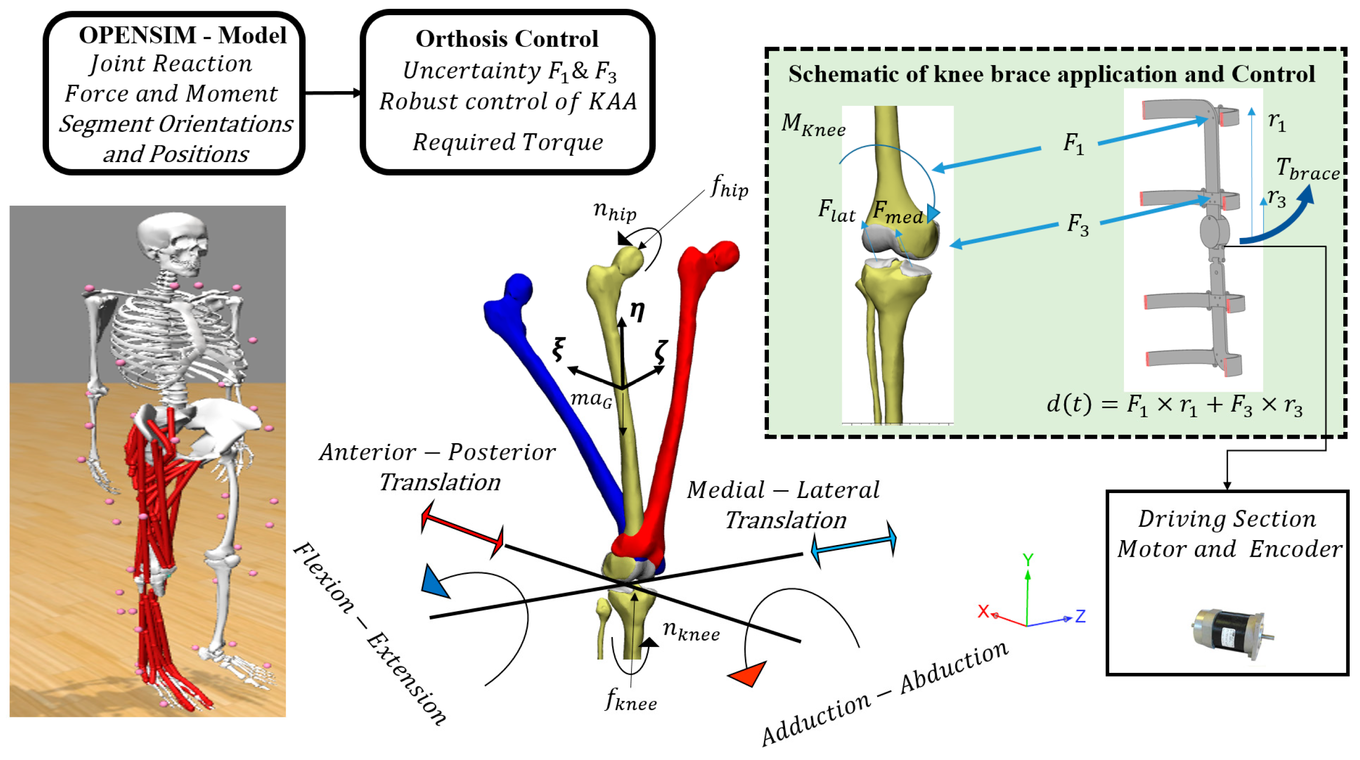
Dynamic loading within human musculoskeletal forces in the gait cycle can benefit the joint unloading treatment process. The inverse dynamic model implemented in OpenSim software was utilized to analyze the joint forces and moments during various movements. This model allowed for a detailed assessment of the biomechanical parameters and provided valuable insights into the load distribution and muscle activations within the knee joint. Additionally, inverse dynamics simulation in OpenSim (V.3.3, SimTK) could provide a comprehensive dynamic model as depicted in Figure 5. The Newton–Euler equations of motion for an unconstrained spatial rigid body are written as [44], subjected to the sum of all the externally applied forces and moments, f and n , respectively.
We sought to determine the unloading force extracted from a control method to control the reference point motion in η direction (axial direction shown in Figure 5). It avoids the knee from the critical threshold of tibia–femur cartilage penetration depth. The authors prove that by controlling the proposed knee model in the sagittal plane [39], a force could be applied at the reference point of the femur. The results of controlling cartilage penetration depth in the sagittal plane are the input data to calculate the optimal KAA. Therefore, we do not explain the control of cartilage penetration with a more detailed description in the present study and it can be studied in [39].
In the knee sagittal plane model, a forward dynamics modeling was presented for the femur to freely translate and rotate with three DOFs, resulting in a dynamics system. However, two degrees of freedom of the system were constrained as the flexion–extension angle and anterior–posterior translation shown in Figure 5. The inputs of the knee model in [39] were anterior–posterior translation, flexion–extension angle θ ζ , net joint reaction force f k n e e , and the moment n k n e e . All externally applied moments of force on the knee were derived by OpenSim analysis. Moreover, the essential output was δ, assisting us in controlling the adduction angle ( θ ξ ).
Figure 5 also shows the driving section including the rotary actuator in the workflow of the study. The angle is controlled to avoid the critical threshold of δ and h s 1 as the cartilage thickness in KOA [39]. The joint reaction force ( f h i p ) and hip moment ( n h i p ) were derived by OpenSim analysis to construct the knee model in the frontal plane. The desired penetration depth and KAA are extracted from the novel knee contact model to derive the inputs of the novel knee contact model. Then, the robust control method is designed to track the desired KAA in the presence of interaction force uncertainty between the orthosis and the user.

2.5. Dynamic and Control Modeling

The amount of knee brace adduction torque applied to the knee is variable because of interaction force changes. Hence, position control is designed to control the relationship between the desired and actual KAA shown in Figure 5. We believe that KAA control is required for KOA unloading. Therefore, the brace applies external torque ( T b r a c e ) by interaction force to distribute the joint reaction force between the medial and lateral compartments. The equation of motion of knee adduction angle can be written as [33,44,45]:
I ξ ω ˙ ξ + I η I ζ ω η ω ζ = F 1 × r 1 + F 3 × r 3 + F m e d × r M A + F l a t × r L A + M m u s c + f h i p × r h i p + n h i p = n k n e e + F 1 × r 1 + F 3 × r 3
where I ξ , I η , and I ζ are the principal moments of inertia, and ω ξ , ω η , and ω ζ and ω ˙ ξ , ω ˙ η , and ω ˙ ζ are the angular velocity and acceleration of the center of mass, respectively. Furthermore, M m u s c is the moment of muscles, n k n e e is the knee moment in KAA direction, and r M A , r L A represent the magnitude of medial and lateral arm contact force ( F m e d , F l a t ) . The dynamic model variables are estimated and calculated by OpenSim inverse dynamic analysis. The novel brace applies torque T b r a c e , which can be used to control the angular displacement in the frontal plane. The interaction force moment ( F 1 × r 1 + F 3 × r 3 ) applied on the knee by the brace can be corrected to control the desired angle of adduction angle tracking. As the brace’s upper cuff is linked to the femur, the upper cuff angle in the adduction direction can distribute the knee loading. The equation of motion of the upper cuff of the brace according to the adduction angle can be written as follows:
I b ξ ω ˙ ξ + I b η I b ζ ω η ω ζ = F 1 × r 1 + F 3 × r 3
where I b ξ , I b η , and I b ζ are the principal moments of inertia and ω ξ , ω η , and ω ζ and ω ˙ ξ , ω ˙ η , and ω ˙ ζ are the angular velocity and acceleration of the center of mass of the upper cuff, respectively. They are calculated by OpenSim inverse kinematic analysis.
The uncertainty of interaction force is unavoidable; however, we assume that the interaction force is controllable in this section. To demonstrate the effectiveness of the proposed control design strategy, it would indeed be beneficial to expand the simulation by considering different scenarios that encompass a diverse range of users, including males and females, as well as different age groups. While using customized data for each case would be ideal, in this study, we used general data reported in certain studies to establish bounded uncertainties for all relevant parameters.
The active control torque T b r a c e applied to the femur is set by the interaction force of the pneumatic mechanism. It means that interaction forces are defined by the control method, and it can be recast as follows:
T b r a c e = F 1 × r 1 + F 3 × r 3 = T n l + T v
where T n l is the term for canceling the nonlinearities, and T v is the term for imposing desired linear dynamics, and it can be written as follows:
T n l = I b η I b ζ ω η ω ζ ,
T v = k d θ e ˙ k p θ e + I b ξ ω ˙ ξ d e s ,
where e = θ θ d is the error vector and e and e ˙ are the error of position and velocity of adduction angle. To make the δ control system stable, the gains k d θ and k p θ need to be chosen to satisfy the desired tracking problem properly. The desired KAA ( θ ξ d e s ), velocity ω ξ d e s , and acceleration ω ˙ ξ d e s are determined to preserve the motion curves to generate healthy knee motion. We assume the θ ξ d e s as follows:
θ ξ d e s = θ ξ P O A δ H r M A
where P O A is the coefficient that reflects the damage percentage and δ H penetration depth of cartilage in healthy cases. Therefore, the linearized and decoupled error equation is as follows:
I e ¨ + k d θ e ˙ + k p θ e = 0
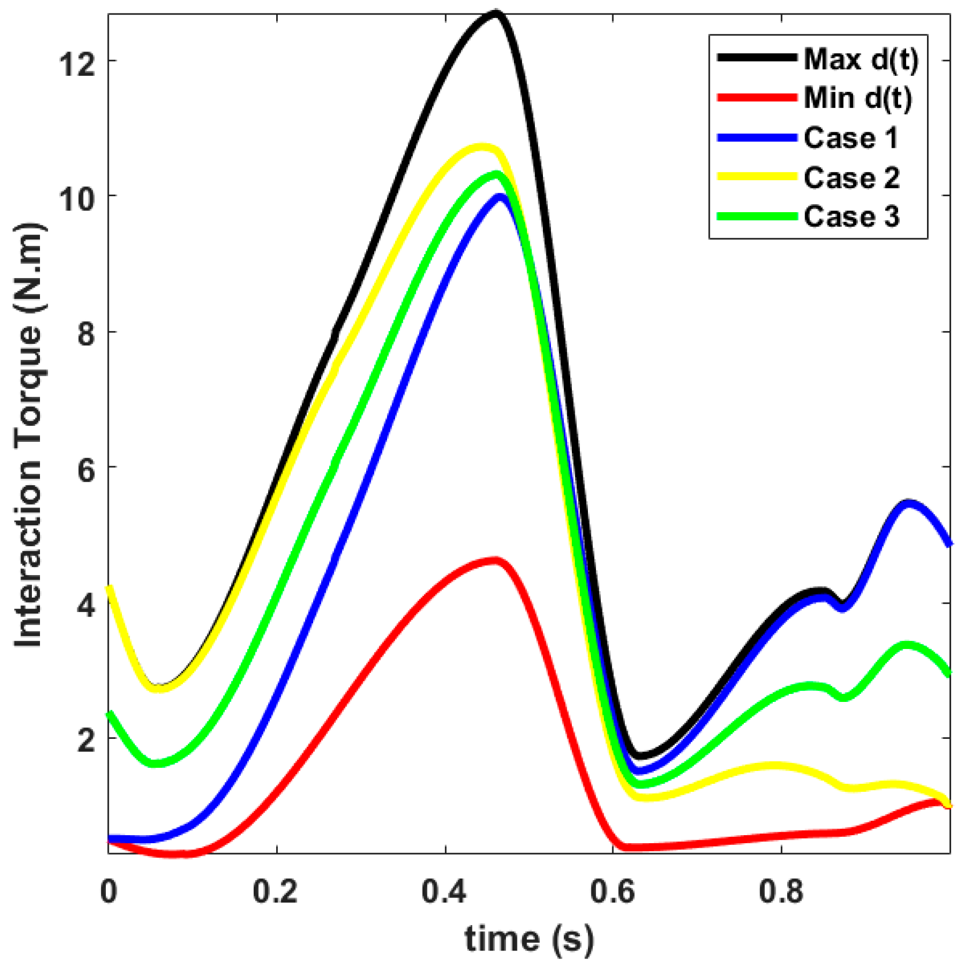
Three-point pressure braces change the external adduction moment to reduce the pressure of the medial compartment. Inspired by the design with variable torque as a function of the walking process in [27], Figure 6 presents this amount of torque based on the measurements. It is a sample demonstration of a changeable orthosis moment over the gait cycle. The gray space in Figure 6 represents the overestimation of the orthosis moment when the tightening force is not deducted. Pollo et al. [26] reported a range of 5.9–11 (Nm) for the orthosis torque in the adduction direction, depending on the orthosis setting. According to the proposed actuator control method, the amount of torque is variable. Even with an accurate measurement, a range must be considered for this torque during the gait.
Robust nonlinear control techniques have demonstrated their effectiveness in solving various practical control problems. To increase the realism, we consider a bounded uncertainty and aim to accurately track the optimal adduction angle. The actuator control procedure involves applying external abduction torque to achieve the desired adduction angle. Therefore, considering system uncertainty d ( t ) as the interactive force between the user and device [46,47] (as shown in Figure 6), the d(t) is used to recast Equation (4):
I b ξ ω ˙ ξ + I b η I b ζ ω η ω ζ = d ( t ) + T b r a c e
In the present problem, the d(t) is defined as follows:
d t = F 1 × r 1 + F 3 × r 3
It might be hard to express the exact torque value of the interaction force, but its range is available. Therefore, we write the nominal model of the system as follows:
I b ξ ω ˙ ξ + I b η I b ζ ω η ω ζ = T b r a c e
To define the controller:
T b r a c e = k d θ e ˙ k p θ e + I θ ¨ a b d a d d d e s + I b η I b ζ ω η ω ζ
Now we recast the proposed control law using the robust control method:
T b r a c e = k d θ e ˙ k p θ e + I θ ¨ a b d a d d d e s + I b η I b ζ ω η ω ζ ν
According to Equation (14), the T b r a c e includes T n l which is the term for canceling the nonlinearities via compensating ucertanities, and T v is the term for imposing desired linear dynamics. T n l and T v can be written as follows:
T n l = I b η I b ζ ω η ω ζ ν
T v = k d θ e ˙ k p θ e + I θ ¨ a b d a d d d e s
The compensation torque ν is designed to eliminate the influence of system uncertainty d ( t ) as the interactive force between the user and the device. Therefore, the error could be formulated as follows:
I e ¨ + k r d θ e ˙ + k r p θ e = d t ν
From Equations (14) and (15), we know that if d t ν 0 and k r d θ , k r p θ are appropriately selected, then e 0 (in the ideal state). In order to eliminate the influence of system uncertainty and disturbance, compensation torques ν ∈R should be designed to ensure d t ν 0 as the time goes to infinity. In the state space form, these linear dynamics can be represented as
X ˙ = x ˙ 1 x ˙ 2 = 0 1 k r p θ k r d θ x 1 x 2 + 0 1 ω X ˙ = A X + b ω ω = d t ν
According to Lyapunov’s theory for robust control (Appendix A), we have [47]
ν = [ X T p b ] T X T p b ρ = [ e e ˙ T p 0 1 ] T e e ˙ T p 0 1 ρ
where ρ is the scalar bound on the uncertainty d(t), we choose Q > 0, and let P > 0 be the unique symmetric positive definite matrix satisfying the Lyapunov equation. Figure 7 shows the block diagram of the actuator control. Accordingly, Equation (18) describes a robust inverse dynamic method that adjusts the abduction torque to track the desired adduction angle. The Lyapunov stability of nonlinear control systems is explained in Appendix A. Robust nonlinear control techniques are demonstrated generally in a block diagram, and we consider a bounded uncertainty named d(t) in Equation (17). T n l and T v are depicted by Equations (15) and (16), whereas the motion equation in the frontal plane is shown by Equation (10).

3. Results

The simulation is based on a previous study with 75% KOA [8]. The amount of control torque on the knee changes when the brace is adjusted through our simulation. The results of this study pertain to knee osteoarthritis, and our proposed unloader brace effectively adjusts the abduction angle using an embedded mechanism. The brace applies an appropriate unloader force, taking into account the contact point and cartilage penetration depth.
With regard to the simulation parameters, the femur mass is assumed to be 3 kg and refers to a subject 1.8 m in height and 76 kg in weight [8]. Critical cartilage penetration depth h s 1 for a knee engaged with 75% KOA is assumed to be 0.5 mm. Unwarranted variations in adduction angle may lead to an overloading of the lateral compartment [24]. Therefore, we used the proposed computational method for three defined cases compatible with Figure 8. Three simulations are presented with different parameters in order to provide a more detailed and comprehensive analysis of the modeling and computational methods. The main parameters for unloading procedure during gait cycle are reported for each cases. For instance, peaks of separation angle are 0.4, 1.7, and 2.2 in the simulation.
For actuation control implementation, the scalar bound on the uncertainty d(t), ρ = 12.68. Additionally, to track the desired KAA with acceptable error, we realize that the saturation function should be used. Hence, if T b r a c e > M a x V a l u e , the saturation function is defined by T b r a c e = s i g n ( T b r a c e ) × M a x V a l u e . The maximum value ( M a x V a l u e ) is determined to be 27.6 Nm.
In the simulation, we take into consideration the contact force, penetration depth, and contact point. Specifically, we calculate the unloading force for a subject with 75% knee osteoarthritis (KOA) based on relevant references [8,39]. The medial penetration depth is calculated according to a certain percentage of KOA [39] as depicted in Figure 8a. In addition, for medial separation distance, the amount of separation angle is demonstrated in Figure 8b. The medial unloading and lateral overloading are shown in Figure 8c,d.
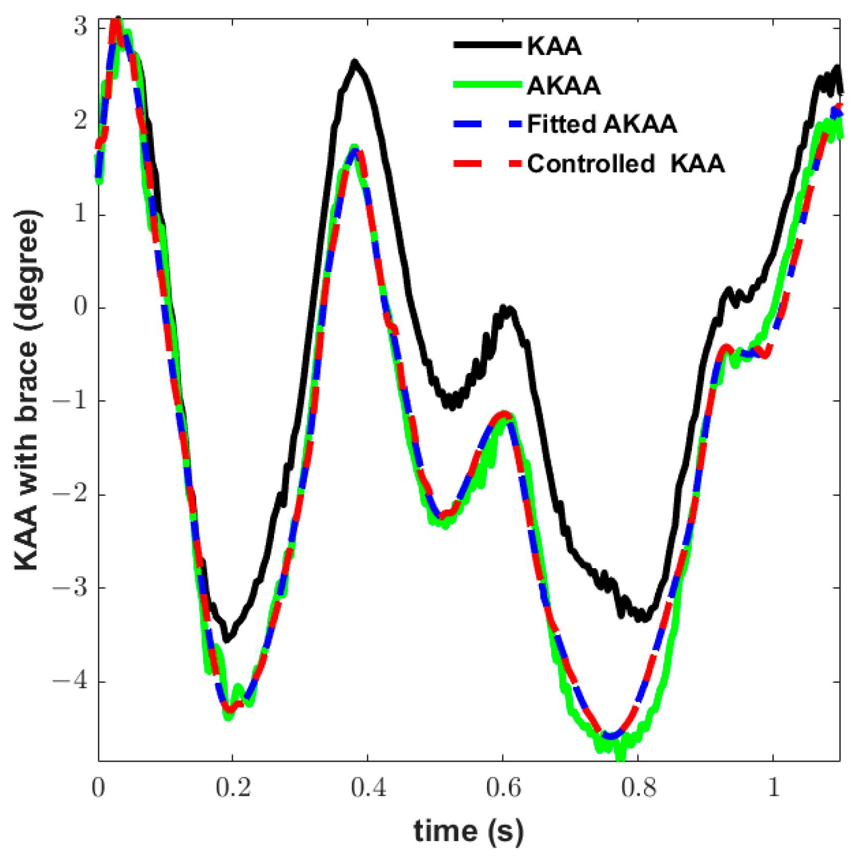
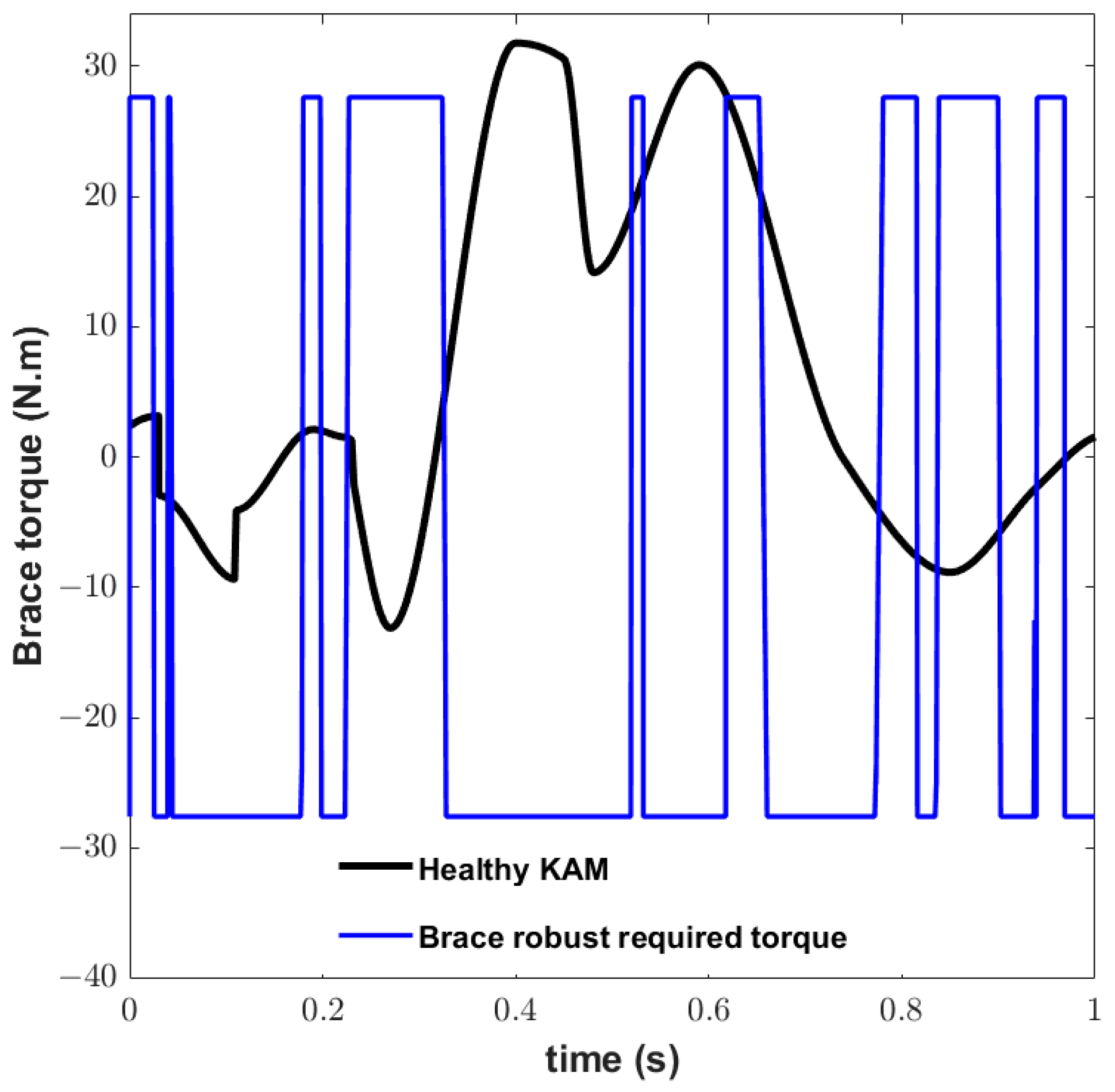
In our approach, altered knee adduction angle (AKAA) is defined according to the changing of KAA. In the next step, Figure 9 demonstrates AKAA and normal KAA. In addition, it illustrates the KAA tracking the fitted AKAA after applying the control torque ( T b r a c e ) mentioned in Equation (9). It is followed by Figure 10, which presents the required torque for tracking desired KAA shown in Figure 9.
The proposed procedure offers significant benefits to patients using the new brace by reducing medial compartment contact force (MCF) and altering knee adduction angle (KAA). Figure 8a illustrates the cartilage’s medial penetration depth in three different cases. In knee osteoarthritis (KOA), where the cartilage thickness is 0.5 mm, it is crucial to keep the penetration depth below a critical threshold. The results of Case 2, which involves intermediate correction of KAA, demonstrate a maximum KAA correction of approximately 1.7° at the first and second peaks of MCF. Notably, Figure 8 illustrates the correction of KAA based on MCF and lateral compartment contact force (LCF) for the first time.
Three cases are simulated and presented in Figure 8, considering three different levels of KAA correction (peaks at 0.4°, 1.7°, and 2.2°) to reduce MCF. Furthermore, the results of these three cases are compared with the unbraced normal mode (0°) case. While Case 3 manages to decrease MCF, it fails to prevent bone-to-bone contact in the medial compartment. On the other hand, both Case 1 and Case 2 successfully prevent bone-to-bone contact, with Case 2 providing intermediate medial penetration reduction and addressing lateral overloading. The second peak of the KAA in this case is 1.7°.
Since KAA rotation is considered for the performance analysis, the desired trajectory is extracted from the normal knee motion [39]. The controlled KAA is demonstrated in Figure 11. Figure 12 shows the brace torque saturated to track the desired trajectory calculated by the robust control method. When the input reaches a certain level, its further increase produces little or no increase in the output. The brace torque displays saturation characteristics while T b r a c e is applied to the femur. The output simply stays around its maximum value and the device is said to be in saturation when this happens, as shown in Figure 12.
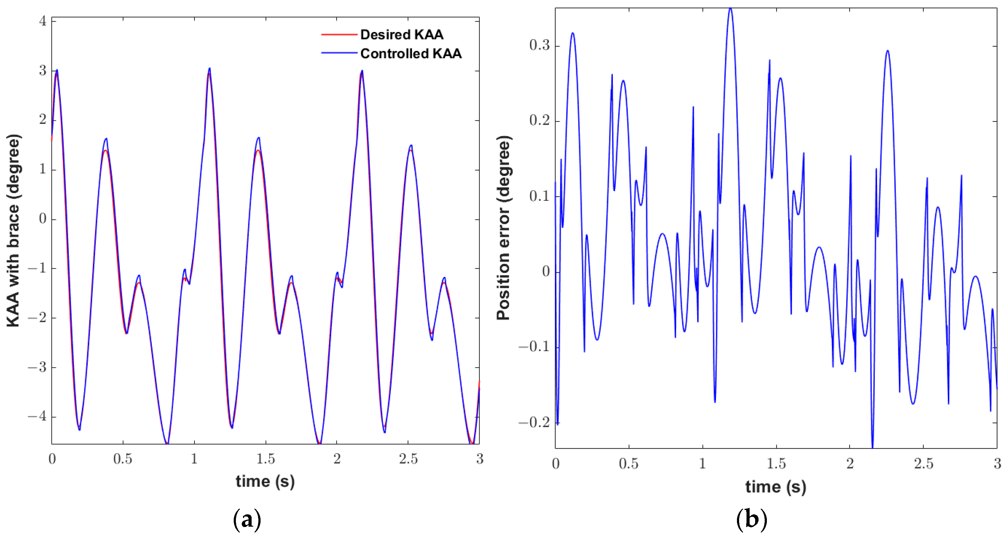
The KAA during three gait cycles is demonstrated in Figure 13 to check the performance of the implemented robust control method. The controller is designed based on considering both the nominal model and some characterization of the model uncertainties. A control term ν is an additional control input that must be defined to overcome the effect of the uncertainty (Equations (A1)–(A4)). The controller uses a high feedback gain value to achieve optimal tracking error. To show the robustness of the controller, uncertainty d ( t ) as the interactive force between the user and device is considered in the control of the brace. It is mainly introduced to mimic the femur motion [46].
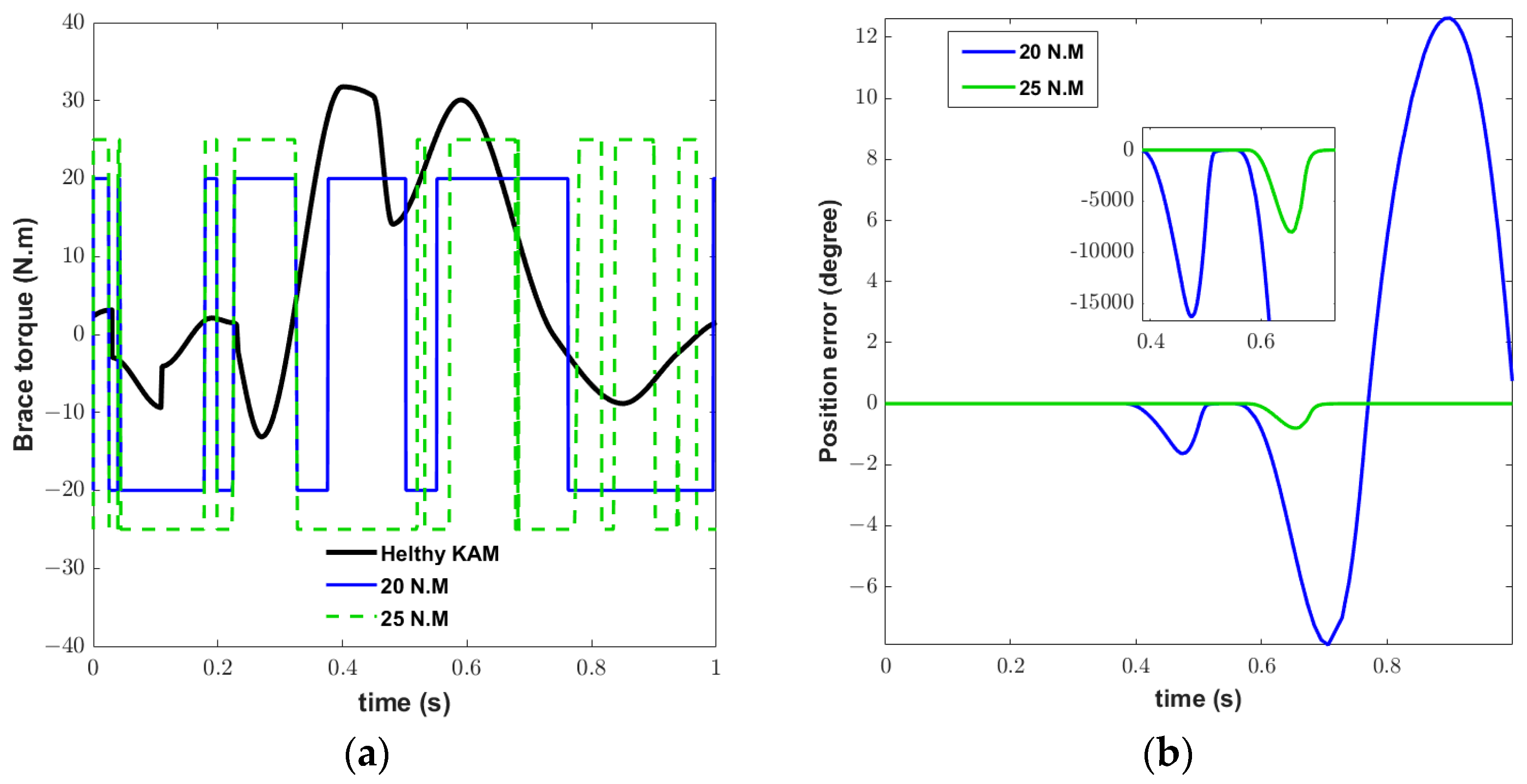
The results demonstrate that the controller applies an acceptable best to specific classes of nonlinear systems and generally requires state measurements. The actuator controller gives the desired tracking error performance when subjected to disturbances. According to the variations in Figure 6, d ( t ) can be assumed. We investigate applied torque influence on tracking desired angle and error of control. According to the saturated function, several amounts of torques are used, as shown in Figure 14, and the minimal torque correlated to acceptable error could be determined to be 27.6 Nm.

4. Discussion

Our research emphasizes the applicability of the schematic of the embedded actuation to various braces, as shown in Figure 2. The main objective of our study is to address the separation of the medial tibiofemoral knee joint, specifically in relation to the parameter δ. We observe a reduction in medial penetration depth of approximately 0.3 mm (as depicted in Figure 8a) through a separation angle of 1.7° (as shown in Figure 8b). The actuator design focuses on the double-hinge actuation mechanism, which effectively corrects the knee adduction angle (KAA). While the separation angle may vary, the maximum observed separation angle of 2.2° results in a separation of 0.43 mm.
In a clinical study conducted by Roudsari et al. [48], female volunteers with medial osteoarthritis were found to benefit from a decrease in the adduction angle of approximately 2° during the stance phase. Our study demonstrates a comparable reduction in the adduction angle, specifically 1.7°. Furthermore, Roudsari et al. [48] confirmed that the distribution of internal forces within the knee joint during gait is primarily influenced by the knee adduction angle, rather than the knee adduction moment. These findings are consistent with previous studies [27,49] that have highlighted the effectiveness of hinge adjustments in the frontal plane in reducing medial compartment forces, rather than relying solely on strap tension increases [50].
It should be notated that using the valgus brace for three months leads to a shift in load from the medial to the lateral compartment [24,51]. While the results depend on the user, we reported the results according to dynamic adduction angle change. Although the adduction angle is not reported in [26], our study showed the same reduction in contact force by less change in KAA.
Another significant aspect to consider is the consistent findings with previous studies [27,52]. It explains that increasing valgus alignment leads to a higher reduced load of the medial compartment. The brace shifts the load from the medial to the lateral compartment, which is thicker than the medial compartment [53]. However, it is important to note that the lateral compartment is not accustomed to this altered loading pattern, which can lead to cartilage degeneration in that region. This phenomenon has been reported in the literature [24,25,53], and our study confirms these findings. Interestingly, apart from studies by the authors of [25,28], no other researchers have quantified the impact of unloader braces on the lateral contact force until now.
Characteristics of included studies are described in Table 1. A brief comparison is demonstrated to clarify the efficiency of our study. Our study results in Case 1 show 0.8 BW medial unloading at the second peak. It is closed to 0.82 BW reported in [25]. Case 2 in our study, with 1.7° alteration of KAA, presents an intermediate δ, lateral overloading, and 1.18 BW medial unloading with 0.36 Nm/kg abduction torque, comparable to the 0.3 BW reported in [28], while the 0.3 BW medial unloading needs 0.1 Nm/kg abduction torque at the second peak. Even though the results are slightly different from the previous studies [25,28], the pattern of all knee brace contributions is quite similar. The variations in the outcomes may arise due to differences in factors such as step lengths, foot shapes, gait patterns, knee condyle shapes, types of braces used, and so on [25]. Even the same person can have different knee moment paths in each cycle, so it may be normal if different people have different knee moments when they wear different types of OA braces.
It is important to note that studies [25,28] focused on evaluating the contribution of specific factors, whereas the present study moves beyond that by calculating the robust abduction torque necessary to effectively distribute the joint reaction force. Our findings demonstrate that a mere 0.43° change in knee adduction angle (KAA) results in a substantial reduction of 600 N at the second peak during the gait cycle, specifically at heel-off. This reduction can be compared to the clinical study conducted by Shriram et al. [25], where they observed an approximate 1° reduction in adduction angle, resulting in a decrease in medial contact force. By highlighting the significance of even small changes in KAA, our study emphasizes the potential impact of precise control over abduction torque for optimizing knee joint mechanics.
Our computational method via the brace design concept can support the knee to achieve these phenomena, such as lateral compartment overloading, bone–bone contact, and unfavorable alteration of KAA. Respecting the logical amount of alteration, the continuous changing of KAA in motion phases is suggested to observe continuous motion without shock and sudden unloading. Subsequently, the brace can be equipped based on the adaptive attitude to triumph over all the noticeable shortages that disturb the critical roles of other knee components, such as fluid synovial, ligament, and meniscus. Furthermore, integration of experimental data will provide further insights and support the practical application of the proposed method.

5. Conclusions

The hypothesis suggests that the combination of the embedded actuation mechanism, computational procedure, and active control in the unloader brace can provide a viable solution for mitigating the challenges associated with KOA and improving the safety and functionality of the knee joint. To effectively correct the adduction knee angle, an embedded actuator was designed based on a realistic model. The addition of a double-hinge mechanism with revolute dampers and mechanical hard stops allows for precise control of the knee adduction angle (KAA) in the brace. In this context, we propose a computational method to reduce the load on the medial compartment in cases of osteoarthritis. Figure 4 provides a visual representation of the relationships between medial and lateral penetration depths, as well as their correlation with the knee adduction angle. By controlling this angle, our proposed method establishes a connection between the adduction angle, contact point, and cartilage penetration depth. A knee forward dynamic model in the frontal plane was discussed in this study. Accordingly, this innovative computational procedure was introduced to extract the biomechanical parameters of the knee and control the actuator.
We realize that there are some obstacles in order to clarify the relation between adduction knee angle and medial and lateral contact force. Then, the most convenient means of overcoming this issue was discovering the correlation between penetration depth and medial and lateral contact force. Unlike typical valgus brace designers, our computational strategy takes into account the influence of lateral overloading induced by medial unloading. We found that a maximum correction of 1.7 degrees effectively unloads the knee and prevents excessive lateral compartment contact force (LCF). Neglecting this phenomenon leads to undesired rotation from adduction to abduction, which places the overloaded lateral compartment at risk.
The outcomes measured from two experimental studies [25,28] were examined. Table 1 demonstrates the efficiency of our study with existing studies to verify the whole procedure. Additionally, to assess the effectiveness of the robust control, an analysis was conducted in the presence of uncertainty in interaction torque. As a result, we were able to quantify the computational changes in KAA and the associated peak lateral compartment overloading 852 N for the specific case study. The required torque in the presence of interaction force is calculated. To determine which torque within the design range exhibited acceptable tracking, several torques were tested. The optimal torque for position control tracking was determined to be 27.6 Nm. As per the differences in case studies and their characteristics, the amount of valgus moment cannot be compared with the literature accurately. However, the main factor of comparison is the pattern and range of alteration, and the results of our study are in good agreement with prior clinical studies [25,28,53].
Our computational method via the brace design concept can support the knee to achieve lateral compartment overloading, bone–bone contact, and adaptive alteration of KAA in motion phases to observe continuous motion without shock and sudden unloading. This brace can help to overcome the shortcomings of other knee components, such as fluid synovial, ligament, and meniscus. Apparently, there are some limitations in our simulation. Although the embedded actuation design might apply to different braces, the influence of muscle activations on knee moments is a crucial parameter that changes when it is adjusted to the knee. It affects the external abduction torque calculation. In future, conducting a preliminary test with healthy individuals is a valuable step in the development and validation process, helping ensure the safety, efficacy, and usability of the proposed method before moving forward with further studies or clinical trials. This may include appropriate justifications and references to benchmarking studies to enhance the credibility and robustness of our proposed experimental design findings.

Author Contributions

Conceptualization, M.B.; methodology, M.B. and A.J.; software, A.J.; validation, M.B. and A.J.; formal analysis, M.B. and A.J.; investigation, M.B. and A.J.; resources, M.B.; data curation, A.J; writing—review and editing, M.B. and A.J.; supervision and project administration, M.B.; All authors have read and agreed to the published version of the manuscript.

Funding

This research received no external funding.

Data Availability Statement

The datasets generated and supporting the findings of this article are obtainable from the corresponding author upon reasonable request. The authors attest that all data for this study are included in the paper. Data generated or the code used during the study are available from the corresponding author by request.

Conflicts of Interest

The authors declare no conflict of interest in preparing this article.

Abbreviations

MCFMedial contact force
KOAKnee osteoarthritis
CFContact forces
KAMKnee adduction moment
KFMKnee flexion moment
KAAKnee adduction angle
LCFLateral contact force
MCFMedial contact force
δCartilage penetration depth
AKAAAltered adduction knee angle

Appendix A

The theory introduced by Lyapunov is the most general approach for studying the stability of nonlinear control systems. As the proof of stability and obtaining ν:
V = 1 2 X T p X > 0
The derivative of the Lyapunov function is
V ˙ = 1 2 X ˙ T p X + 1 2 X T p X ˙
According to Equations (16) and (A2), it can be recast as follows:
V ˙ = 1 2 X T ( A T p + p A ) X + X T p b ω
Defining Q as the positive matrix:
V ˙ = 1 2 X T Q X + X T p b ω
The condition to become negative is
V ˙ 0 X T p b ω < 0
and then, we have
X T p b ( d t ν ) < 0
X T p b d t < X T p b ν
Considering d(t) has a defined range, the basic assumption is that the uncertainty range is known:
[ d t ] < ρ
X T p b d t < X T p b . d ( t ) < X T p b . ρ
X T p b ν = X T p b   ρ
ν = [ X T p b ] T X T p b   ρ

References

  1. Dieppe, P.; Cushnaghan, J.; Young, P.; Kirwan, J. Prediction of the progression of joint space narrowing in osteoarthritis of the knee by bone scintigraphy. Ann. Rheum. Dis. 1993, 52, 557–563. [Google Scholar] [CrossRef] [PubMed] [Green Version]
  2. Koshino, T.; Murase, T.; Saito, T. Medial opening-wedge high tibial osteotomy with use of porous hydroxyapatite to treat medial compartment osteoarthritis of the knee. J. Bone Jt. Surg. 2003, 85, 78–85. [Google Scholar] [CrossRef]
  3. Javanfar, A.; Bamdad, M. (Eds.) Knee brace control for reduction of medial compartment load. In Proceedings of the 10th RSI International Conference on Robotics and Mechatronics (ICRoM), Tehran, Iran, 15–17 November 2022. [Google Scholar]
  4. Herscovici, D., Jr.; Sammarco, G.J.; Sammarco, V.J.; Scaduto, J.M.; Scaduto, J.M. Pantalar arthrodesis for post-traumatic arthritis and diabetic neuroarthropathy of the ankle and hindfoot. Foot Ankle Int. 2011, 32, 581–588. [Google Scholar] [CrossRef] [PubMed]
  5. Karatsidis, A. Kinetic Gait Analysis Using Inertial Motion Capture: New Tools for Knee Osteoarthritis. Ph.D. Thesis, University of Twente, Enschede, The Netherlands, 2018. [Google Scholar] [CrossRef]
  6. Su, Q.; Pei, Z.; Tang, Z.; Liang, Q. Design and Analysis of a Lower Limb Loadbearing Exoskeleton. Actuators 2022, 11, 285. [Google Scholar] [CrossRef]
  7. Liu, C.; Wang, Z.; Liu, J.; Xu, Y. Cost-Effectiveness Analysis Based on Intelligent Electronic Medical Arthroscopy for the Treatment of Varus Knee Osteoarthritis. J. Healthc. Eng. 2021, 2021, 5569872. [Google Scholar] [CrossRef] [PubMed]
  8. Machado, M.M.F. A Multibody Approach to the Contact Dynamics: A Knee Joint Application. Ph.D. Thesis, Universidade do Minho, Braga, Portugal, 2013. [Google Scholar]
  9. Lee, P.Y.; Winfield, T.G.; Harris, S.R.; Storey, E.; Chandratreya, A. Unloading knee brace is a cost-effective method to bridge and delay surgery in unicompartmental knee arthritis. BMJ Open Sport Exerc. Med. 2017, 2, e000195. [Google Scholar] [CrossRef] [Green Version]
  10. Lacquaniti, F.; Maioli, C. Independent control of limb position and contact forces in cat posture. J. Neurophysiol. 1994, 72, 1476–1495. [Google Scholar] [CrossRef] [PubMed]
  11. Harrington, I.J. Static and dynamic loading patterns in knee joints with deformities. J. Bone Jt. Surg. 1983, 65, 247–259. [Google Scholar] [CrossRef] [PubMed]
  12. Lindsey, B.W. Gait Modification to Reduce Peak Knee Abduction Moment. Ph.D. Thesis, George Mason University, Fairfax, VA, USA, 2021. [Google Scholar]
  13. Bowd, J. Does Gait Retraining Have the Potential to Slow Osteoarthritis Development and Prolong the Benefits of Knee Realignment Surgery? Ph.D. Thesis, Cardiff University, Cardiff, UK, 2022. [Google Scholar]
  14. Rynne, R.; Le Tong, G.; Cheung, R.T.; Constantinou, M. Effectiveness of gait retraining interventions in individuals with hip or knee osteoarthritis: A systematic review and meta-analysis. Gait Posture 2022, 95, 164–175. [Google Scholar] [CrossRef]
  15. Walter, J.P.; D’Lima, D.D.; Colwell, C.W., Jr.; Fregly, B.J. Decreased knee adduction moment does not guarantee decreased medial contact force during gait. J. Orthop. Res. 2010, 28, 1348–1354. [Google Scholar] [CrossRef] [Green Version]
  16. Stoltze, J.S.; Rasmussen, J.; Andersen, M.S. On the biomechanical relationship between applied hip, knee and ankle joint moments and the internal knee compressive forces. Int. Biomech. 2018, 5, 63–74. [Google Scholar] [CrossRef] [Green Version]
  17. Kumar, V.; Hote, Y.V.; Jain, S. (Eds.) Review of exoskeleton: History, design and control. In Proceedings of the 2019 3rd International Conference on Recent Developments in Control, Automation & Power Engineering (RDCAPE), Noida, India, 10–11 October 2019; IEEE: Piscataway, NJ, USA, 2019. [Google Scholar]
  18. Mahdi, S.M.; Yousif, N.Q.; Oglah, A.A.; Sadiq, M.E.; Humaidi, A.J.; Azar, A.T. Adaptive Synergetic Motion Control for Wearable Knee-Assistive System: A Rehabilitation of Disabled Patients. Actuators 2022, 11, 176. [Google Scholar] [CrossRef]
  19. McGibbon, C.A.; Brandon, S.C.; Brookshaw, M.; Sexton, A. Effects of an over-ground exoskeleton on external knee moments during stance phase of gait in healthy adults. Knee 2017, 24, 977–993. [Google Scholar] [CrossRef] [PubMed]
  20. Walsh, C.J.; Endo, K.; Herr, H.M. A Quasi-passive leg exoskeleton for load-carrying augmentation. Int. J. Hum. Robot. 2007, 4, 487–506. [Google Scholar] [CrossRef]
  21. Shamaei, K.; Adams, A.A.; Cenciarini, M.; Gregorczyk, K.N.; Dollar, A.M. (Eds.) Preliminary investigation of effects of a quasi-passive knee exoskeleton on gait energetics. In Proceedings of the 36th Annual International Conference of the IEEE Engineering in Medicine and Biology Society, Chicago, IL, USA, 26–30 August 2014; IEEE: Piscataway, NJ, USA, 2014. [Google Scholar]
  22. Ramsey, D.K.; Russell, M.E. Unloader Braces for Medial Compartment Knee Osteoarthritis: Implications on Mediating Progression. Sport. Health 2009, 1, 416–426. [Google Scholar] [CrossRef] [PubMed] [Green Version]
  23. Budarick, A.R.; MacKeil, B.E.; Fitzgerald, S.; Cowper-Smith, C.D. Design Evaluation of a Novel Multicompartment Unloader Knee Brace. J. Biomech. Eng. 2019, 142, 014502. [Google Scholar] [CrossRef] [Green Version]
  24. Parween, R.; Shriram, D.; Mohan, R.E.; Lee, Y.H.D.; Subburaj, K. Methods for evaluating effects of unloader knee braces on joint health: A review. Biomed. Eng. Lett. 2019, 9, 153–168. [Google Scholar] [CrossRef]
  25. Shriram, D.; Yamako, G.; Chosa, E.; Lee, Y.H.D.; Subburaj, K. Effects of a valgus unloader brace in the medial meniscectomized knee joint: A biomechanical study. J. Orthop. Surg. Res. 2019, 14, 44. [Google Scholar] [CrossRef]
  26. Pollo, F.E.; Otis, J.C.; Backus, S.I.; Warren, R.F.; Wickiewicz, T.L. Reduction of Medial Compartment Loads with Valgus Bracing of the Osteoarthritic Knee. Am. J. Sport. Med. 2002, 30, 414–421. [Google Scholar] [CrossRef]
  27. Cusin, E.; Honeine, J.; Schieppati, M.; Rougier, P. A Simple Method for Measuring the Changeable Mechanical Action of Unloader Knee Braces for Osteoarthritis. IRBM 2018, 39, 136–142. [Google Scholar] [CrossRef]
  28. Brandon, S.C.; Brown, M.J.; Clouthier, A.L.; Campbell, A.; Richards, J.D.; Deluzio, K.J. Contributions of muscles and external forces to medial knee load reduction due to osteoarthritis braces. Knee 2019, 26, 564–577. [Google Scholar] [CrossRef]
  29. Adouni, M.; Shirazi-Adl, A. Partitioning of knee joint internal forces in gait is dictated by the knee adduction angle and not by the knee adduction moment. J. Biomech. 2014, 47, 1696–1703. [Google Scholar] [CrossRef]
  30. Zeighami, A. Tibiofemoral Contact Areas and Contact Forces in Healthy and Osteoarthritic Subjects. Ph.D. Thesis, École de Technologie Supérieure, Montreal, QC, Canada, 2018. [Google Scholar]
  31. Javanfar, A.; Bamdad, M. Development of a planar multibody model of the knee joint with contact mechanics. Iran. J. Biomed. Eng. 2022, 16, 111–120. [Google Scholar]
  32. Zhou, X.; Chen, X. Design and Evaluation of Torque Compensation Controllers for a Lower Extremity Exoskeleton. J. Biomech. Eng. 2020, 143, 011007. [Google Scholar] [CrossRef] [PubMed]
  33. Zhang, L.; Liu, Y.; Wang, R.; Smith, C.; Gutierrez-Farewik, E.M. Modeling and simulation of a human knee exoskeleton’s assistive strategies and interaction. Front. Neurorobot. 2021, 15, 620928. [Google Scholar] [CrossRef]
  34. Jerbi, H.; Al-Darraji, I.; Tsaramirsis, G.; Ladhar, L.; Omri, M. Hamilton–Jacobi Inequality Adaptive Robust Learning Tracking Controller of Wearable Robotic Knee System. Mathematics 2023, 11, 1351. [Google Scholar] [CrossRef]
  35. Richards, R.E.; Andersen, M.S.; Harlaar, J.; Van Den Noort, J.C. Relationship between knee joint contact forces and external knee joint moments in patients with medial knee osteoarthritis: Effects of gait modifications. Osteoarthr. Cartil. 2018, 26, 1203–1214. [Google Scholar] [CrossRef] [PubMed] [Green Version]
  36. Reeves, N.D.; Bowling, F.L. Conservative biomechanical strategies for knee osteoarthritis. Nat. Rev. Rheumatol. 2011, 7, 113–122. [Google Scholar] [CrossRef] [PubMed]
  37. Delp, S.L.; Anderson, F.C.; Arnold, A.S.; Loan, P.; Habib, A.; John, C.T.; Guendelman, E.; Thelen, D.G. OpenSim: Open-Source Software to Create and Analyze Dynamic Simulations of Movement. IEEE Trans. Biomed. Eng. 2007, 54, 1940–1950. [Google Scholar] [CrossRef] [Green Version]
  38. Bingham, J.T.; Papannagari, R.; Van de Velde, S.K.; Gross, C.; Gill, T.J.; Felson, D.T.; Rubash, H.E.; Li, G. In vivo cartilage contact deformation in the healthy human tibiofemoral joint. Rheumatology 2008, 47, 1622–1627. [Google Scholar] [CrossRef] [Green Version]
  39. Javanfar, A.; Bamdad, M. A developed multibody knee model for unloading knee with cartilage penetration depth control. Proc. Inst. Mech. Eng. Part H J. Eng. Med. 2022, 236, 1528–1540. [Google Scholar] [CrossRef]
  40. Bamdad, M.; Zarshenas, H. Robotic rehabilitation with the elbow stiffness adjustability. Modares Mech. Eng. 2015, 14, 151–158. [Google Scholar]
  41. Gross, K.D.; Hillstrom, H.J. Noninvasive Devices Targeting the Mechanics of Osteoarthritis. Rheum. Dis. Clin. N. Am. 2008, 34, 755–776. [Google Scholar] [CrossRef] [PubMed]
  42. Wang, J.; Li, X.; Huang, T.-H.; Yu, S.; Li, Y.; Chen, T.; Carriero, A.; Oh-Park, M.; Su, H. Comfort-Centered Design of a Lightweight and Backdrivable Knee Exoskeleton. IEEE Robot. Autom. Lett. 2018, 3, 4265–4272. [Google Scholar] [CrossRef]
  43. Lenhart, R.L.; Kaiser, J.; Smith, C.; Thelen, D.G. Prediction and Validation of Load-Dependent Behavior of the Tibiofemoral and Patellofemoral Joints During Movement. Ann. Biomed. Eng. 2015, 43, 2675–2685. [Google Scholar] [CrossRef] [PubMed] [Green Version]
  44. Winter, D.A. Biomechanics and Motor Control of Human Movement; John Wiley & Sons: Hoboken, NJ, USA, 2009. [Google Scholar]
  45. Robertson, D.G.E.; Caldwell, G.E.; Hamill, J.; Kamen, G.; Whittlesey, S. Research Methods in Biomechanics; Human kinetics: Champaign, IL, USA, 2013. [Google Scholar]
  46. Wu, J.; Gao, J.; Song, R.; Li, R.; Li, Y.; Jiang, L. The design and control of a 3DOF lower limb rehabilitation robot. Mechatronics 2016, 33, 13–22. [Google Scholar] [CrossRef]
  47. Bamdad, M.; Parivash, F. Integrated active and passive gravity compensation method for a cable-actuated elbow rehabilitation robot. In Proceedings of the 2015 3rd RSI International Conference on Robotics and Mechatronics (ICROM), Tehran, Iran, 7 October 2015; pp. 79–84. [Google Scholar]
  48. Roodsari, R.B.; Esteki, A.; Aminian, G.; Ebrahimi, I.; Mousavi, M.E.; Majdoleslami, B.; Bahramian, F. The effect of orthotic devices on knee adduction moment, pain and function in medial compartment knee osteoarthritis: A literature review. Disabil. Rehabil. Assist. Technol. 2016, 12, 441–449. [Google Scholar] [CrossRef] [PubMed]
  49. Komistek, R.D.; Dennis, D.A.; Northcut, E.J.; Wood, A.; Parker, A.W.; Traina, S.M. An in vivo analysis of the effectiveness of the osteoarthritic knee brace during heel-strike of gait. J. Arthroplast. 1999, 14, 738–742. [Google Scholar] [CrossRef] [PubMed]
  50. Segal, N.A. Bracing and Orthoses: A Review of Efficacy and Mechanical Effects for Tibiofemoral Osteoarthritis. PMR 2012, 4, S89–S96. [Google Scholar] [CrossRef]
  51. Neville, S.R.; Brandon, S.C.; Brown, M.J.; Deluzio, K.J. Validation of method for analysing mechanics of unloader brace for medial knee osteoarthritis. J. Biomech. 2018, 76, 253–258. [Google Scholar] [CrossRef] [PubMed]
  52. Kutzner, I.; Küther, S.; Heinlein, B.; Dymke, J.; Bender, A.; Halder, A.M.; Bergmann, G. The effect of valgus braces on medial compartment load of the knee joint—In vivo load measurements in three subjects. J. Biomech. 2011, 44, 1354–1360. [Google Scholar] [CrossRef] [PubMed]
  53. Koo, S.; Andriacchi, T.P. A comparison of the influence of global functional loads vs. local contact anatomy on articular cartilage thickness at the knee. J. Biomech. 2007, 40, 2961–2966. [Google Scholar] [CrossRef] [PubMed] [Green Version]
Figure 1. Unloader devices for knee CF reduction. (a) Loadbearing exoskeleton with muscle–bone model of the lower limb for gaiting [6] https://www.mdpi.com/2076-0825/11/10/285. (b) The Spring Loaded knee brace is an innovative type of offloading knee brace https://www.springloaded.com/knee-braces/top-five-offloader-knee-braces/. (c) Adaptive synergetic motion control [18] https://www.mdpi.com/2076-0825/11/7/176. (d) Donjoy knee brace for people suffering from anterior knee pain https://www.medicalexpo.com/prod/donjoy/product-96003-603081.html.
Actuators 12 00256 g001
Figure 2. Schematic of designed brace with embedded KAA control mechanism hinge compared with traditional braces.
Actuators 12 00256 g002
Figure 3. Knee model in sagittal plane with a schematic of two bodies in different states: (a) contact state; (b) separation state.
Actuators 12 00256 g003
Figure 4. Separation angle ( θ ξ s ) relation with medial separation distance.
Actuators 12 00256 g004
Figure 5. Workflow of the computational procedure including principle elements. The blue femur rotates in knee flexion–extension direction and the red one rotates in KAA direction.
Actuators 12 00256 g005
Figure 6. Variable orthosis moment over the gait cycle. Red line is orthosis moment without subtracting the tightening force measured during orthosis inactivation (static knee flexion). Black line indicates the deducted tightening force.
Actuators 12 00256 g006
Figure 7. The block diagram of the actuator control.
Actuators 12 00256 g007
Figure 8. Variation for unloading procedure in three chosen cases. (a) Cartilage penetration depth δ versus time demonstrating the medial separation distance; (b) separation angle; (c) medial compartment contact force; (d) overloading of lateral compartment.
Actuators 12 00256 g008
Figure 9. KAA before and after applying controlled torque. Before: knee adduction angle (KAA), altered knee adduction angle (AKAA). After: controlled KAA (red), fitted AKAA (blue).
Actuators 12 00256 g009
Figure 10. Required brace moment for tracking KAA variation The actuator torque T b r a c e (blue curve) is applied to the femur.
Actuators 12 00256 g010
Figure 11. Control performance for tracking KAA.
Actuators 12 00256 g011
Figure 12. The required brace moment for tracking a fitted AKAA.
Actuators 12 00256 g012
Figure 13. Robust control of KAA for three gait cycles. (a) KAA after applying control torque; (b) position error of controlled KAA.
Actuators 12 00256 g013
Figure 14. Robust actuator control of KAA for a gait cycle with several saturated torques: (a,b) applied torque (20, 25 Nm) and position error (c,d) applied torque (27.4, 27.5 Nm) and position error; (e,f) applied torque (27.6, 28 Nm) and position error.
Actuators 12 00256 g014aActuators 12 00256 g014b
Table 1. Change in knee contact loads (medial and lateral) and abduction moment peak for different bracing.
OA Brace Type/
Research
Medial Unloading
(BW)
Lateral Overloading (BW)Abduction Torque (Nm/kg)Separation Angle
(Degree)
Valgus Brace
Alignment 8° in [25]
0.82
(600 N/74 Kg)
0.55
(400 N/74 Kg)
-1
Three-Point Bending Double Upright in [28]0.30.20.1-
Unloader Brace
Present study
Case I0.80.760.250.43
Case II1.181.140.361.7
Disclaimer/Publisher’s Note: The statements, opinions and data contained in all publications are solely those of the individual author(s) and contributor(s) and not of MDPI and/or the editor(s). MDPI and/or the editor(s) disclaim responsibility for any injury to people or property resulting from any ideas, methods, instructions or products referred to in the content.