Abstract
Wearable robots have become increasingly prevalent in various applications, including rehabilitation, power augmentation, and assistance. However, one of the challenges in designing wearable robots is how to attach them to the human body. The attachment method should be secure, reliable, comfortable, effective, and controlled for the user. Moreover, the attachment points should not interfere with the user’s daily activities, and the attachment process should not be time-consuming or complicated. Typical straps nowadays require a time-consuming and cumbersome donning and doffing procedure from therapists for users needing rehabilitation therapy. Therefore, we propose a novel pneumatically actuated soft strap to enclose the limb and automate part of the strapping procedure. This paper proposes a preliminary design utilizing soft bending actuators for attaching physical interfaces to humans, with integrated active elements for facilitating and automating the strapping process. Finite element analysis was conducted to assess pressure requirements, bending curvature, and geometry, with simulation results demonstrating a promising agreement, with a root mean square error (RMSE) of 3.4° in bending angle. In the future, an additional locking mechanism would be required to provide the necessary holding force and fully constrain the limb.
1. Introduction
Wearable robots and exoskeletons have experienced an impressive rise in interest and development since the early 1960s. There are now devices that provide effective assistance to people with musculoskeletal disabilities or those in need of rehabilitation, but also devices that enhance physical performance [1]. This is possible because of the close interaction between the device and the user, which transmits forces and torques from the robot to the human. These transmissions are performed through wearable interfaces, such as cuffs or orthoses, which serve as the connection points between the robot and the user. Typically, these interfaces are attached to the limbs through straps, which enable load transmission and allow for the donning and doffing of the interface [2]. However, there are several adverse events reported in the literature that could cause severe injuries to users of wearable robots [3,4].
Several of these injuries are caused by incorrect donning. This can create excessive interaction pressure within the physical interface, leading to soft tissue injuries and pressure ulcers. Furthermore, because of soft tissue compliance, relative motion along the subject’s limb can occur and cause further harm by applying shear forces to the skin [5]. This excessive relative motion creates misalignment between the user’s joints and exoskeleton joints, causing parasitic interaction forces and torques that can alter the natural muscle activity pattern of wearers [6].
A certain level of expertise is generally needed to properly place and attach the physical interface from exoskeletons and rehabilitation robots, which can be expensive and not feasible in the long term [6]. Users with motor disabilities face challenges when donning the straps, as well as adjusting the tightness of straps [7]. This can be due to their motor limitations or sensory impairment, which may prevent them from applying the correct tension [8]. Consequently, a system that can automatically don and control the strap tightness is needed. These aspects pertain to the design of an active physical interface in contrast to its passive counterparts.
Active physical interfaces already exist [9]. However, few of them are intended for use in wearable robots. Hasegawa et al. are among the few researchers who have developed active interfaces systems for exoskeletons and rehabilitation robots for the elderly and paralyzed patients [8,10] by developing an automatic pressure regulation inside. In [8], a system was developed using two sets of three different active air mat chambers as physical interface fasteners, placed along the length of the forearm. The pressure distribution on each air mat chamber is monitored and, thanks to the particular layout of the sets of air chambers, they can change the contact pressure by activating or deactivating certain air mats depending on the blood flow restriction and the time spent wearing the active cuff. In [10], they used pneumatic actuation as mechanical modules (seen as mechanical “fingers”) that can automatically enclose the upper limb by deforming the modules with compressed air. The enclosure is based on magnets attached at the ends of both fingers. While these results serve as precursors to the development of an active interface, the utilization of straps instead of air mat chambers is a potential avenue for exploration. Straps can offer a higher degree of security and adjustability, allowing for a personalized and comfortable fit by being tailored to the individual’s body shape. In contrast, air mat chambers may not provide the same level of customization, leading to potential issues with fit and comfort, particularly for individuals with non-standard body shapes.
The common aspect between these designs is that they are pneumatically actuated. Pneumatic actuators, which are typically made of soft compliant materials such as rubber or silicone, enable safe interaction between the assistive robot and the user, which is an essential requirement [11]. These soft pneumatic actuators are used in a variety of applications, such as robotics, medical devices, and wearable technologies, particularly for human body motion; for instance, for the evaluation of a prosthetic hand [12]. The utilization of soft bending actuators that are pneumatically or hydraulically actuated by human body motion has enabled significant advancements in the field of wearable robotics and assistive devices. These novel actuators possess a distinctive combination of flexibility, compliance, and adaptability, rendering them highly suitable for applications involving close interaction with the human body. Designed to emulate the bending motion of natural biological systems such as muscles and tendons, soft bending actuators leverage pneumatic or hydraulic pressure to achieve controlled deformations, enabling the generation of bending or twisting motions [13]. Importantly, the actuation of these actuators can be directly linked to human body movements, facilitating intuitive and natural control. By integrating soft bending actuators with human body motion, promising opportunities arise for the development of ergonomic and user-friendly wearable devices. Leveraging the body’s inherent motions and biomechanics, these actuators can provide assistance, enhance physical capabilities, and significantly improve the overall user experience. The applications of soft bending actuators span a wide range, encompassing prosthetics, exoskeletons, rehabilitation devices, and haptic interfaces, among others [14,15].
In the rehabilitation context, soft pneumatic networks (PneuNets) are a common solution for creating the bending effect with a straightforward design [16]. Nevertheless, soft bending pneumatic actuators such as PneuNets have not yet been used to strap humans to wearable robots, despite their potential for providing an effective strapping interface. This represents a notable gap in the existing literature, given that the strapping procedure plays a crucial role in wearable robotics by guaranteeing user comfort, safety, and stability. The use of soft bending pneumatic actuators during the strapping procedure has the potential to improve user comfort, safety, and stability in wearable robotics. While there has been some investigation into this area, there is still a need for further exploration to fully understand the benefits of soft bending pneumatic actuators in comparison to rigid or non-compliant strapping interfaces and to identify any potential limitations or drawbacks. It is important to emphasize the importance of maintaining a strong grip when designing typical PneuNets. However, our primary goal is not focused on delivering gripping force through PneuNets. Instead, our main focus is to achieve a conforming enclosure of the limb. To ensure that the strap is firmly fastened, we intend to utilize an alternative mechanism that is beyond the scope of this manuscript. This mechanism will be triggered once the limb is fully enclosed within the actuator.
Our paper investigates whether a soft bending actuator can serve as an automatic enclosure system for physical human-wearable robot interfaces by wrapping the upper limb using only compressed air with a suitable bending angle to achieve a complete wrapping of the limb, as shown in Figure 1.
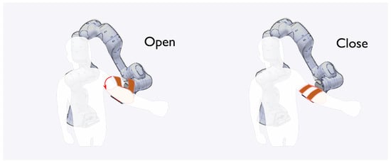
Figure 1.
The soft bending actuators are utilized as straps to envelop the user’s limb by applying air pressure and to exert adequate pressure on the soft tissues, thereby mitigating any potential safety or comfort issues. The left configuration illustrates the user donning their arm onto the interface, whereas the right configuration depicts the user being fully secured to the interface after the straps are actuated by pressurized air.
These actuators are designed for upper arm application, but the designs can be expanded for lower limbs. The presented actuators were designed following the same architecture as the PneuNets technique [16]. Similarly to [14,17], the concept of PneuNets will be used and a set of requirements will be defined to automatically enclose the upper limb. Indeed, compared with previous works where these soft bending actuators are used in human–robot interaction for flexion–extension for the fingers for instance, our soft bending actuator does need a strong curvature to close the interface efficiently and interact with specific zones of the human limb to not compromise comfort.
The manuscript is structured as follows. In Section 2.1, we establish the necessary requirements for enclosing the upper arm and implement them within a finite element analysis software (ABAQUS CAE 2022 version 6.22-1, Dassault Systemes, Vélizy-Villacoublay, France). Next, in Section 2.3, we obtain from the simulation key outputs of interest, including bending curvature, pressure, material, and geometry. In Section 2.4, the manufacturing and fabrication processes of the soft bending actuators are also described. Subsequently, the experimental protocol using the manufactured actuator is presented. Thereafter, in Section 3, the results of the simulation and the prototype are presented and the discussion of all the results is depicted in Section 4. Finally, we present the conclusions at the end of the manuscript.
2. Materials and Methods
2.1. Actuator Requirements
The purpose of the presented soft bending actuator is to enclose an upper limb that represents a 95th percentile male/female arm to a physical interface to couple to either an exoskeleton or rehabilitation robot.
The following outlines the requirements necessary for achieving an automatically closing strap mechanism that prioritizes both optimal comfort and safety for rehabilitation tasks. All requirements are summarized in Table 1.

Table 1.
Requirements of the designed soft bending actuator.
- The bending angle is the amount of curvature or bending that occurs in the actuator when it is subjected to a load or pressure. In other words, it is the angle between the original, unbent position of the actuator and its bent position. The soft actuator that is designed in this paper should be able to achieve a range from 0 to 180° maximum (see angle convention in Figure 2). In the field of soft robotics, the half-angle convention is frequently utilized to determine the bending angle of an actuator. This convention entails dividing the angle by two, thereby accounting for the curved shape of the actuator’s bending motion rather than a linear one.
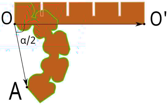 Figure 2. Bending angle of soft pneumatic bending actuators. The vectors are defined by the node at each end of the actuator and therefore an angle can be obtained. When measuring the bending angle, we use the half-angle convention, which means that the angle is divided by 2. This convention is commonly used in the field of soft robotics to account for the fact that the actuator bends in a curved shape rather than a straight line.Indeed, since the active straps will run from one end of a rigid shell (i.e., the physical interface) to the other, the bending angle should be defined such that a limb can be inserted into the interface when it is open, and that the strap can be completely closed once the limb is inside (see Figure 3). Nevertheless, given that the actuator merely needs to reach the highest point at the opposite end of the interface to establish the enclosure, a bending angle of roughly 145° is the minimum required to guarantee the closure of the interface.
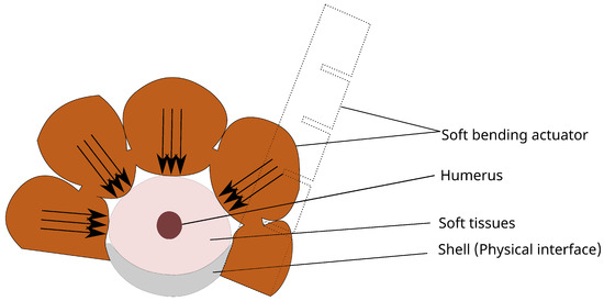 Figure 3. Cross-sectional view of a soft bending actuator enclosing an upper arm. The dotted actuator shows the strap in the initial position without any actuation and the colored actuator shows the strap when fully actuated enclosing the limb of interest. The bottom wall of the chambers compresses the soft tissue of the user. The maximum bending angle allowed in this design is 180° to let the actuator go from one side to another and to enclose the limb, while 145° is the minimum required bending angle to enclose the limb, taking into account the highest point of the interface. Emphasizing the importance of the grip force in the PneuNets design, our primary goal is to first enclose the limb. To secure the strap, we will utilize an alternative mechanism, such as a locking mechanism, which will be discussed in future work and activated upon full enclosure within the actuator.
 - Any additional air put into the system after completing the desired angle (after enclosing the limb) will primarily serve to deform the chambers inside the actuator and especially to bulge out the one at the base of the actuator, where the soft tissues are (see Figure 3). This approach applies pressure on the soft tissue, depending on the region where the interaction between the soft tissue and the actuator is transpiring. In theory, the optimal solution would entail an infinite number of chambers to distribute the pressure uniformly from the bottom walls to the soft tissues. However, increasing the number of chambers decreases the amount of pressure each can individually sustain, and raises the probability of leaks and failures, which eventually undermines reliability and durability over time. Thus, we would rather prioritize the maximization of each chamber’s area to avert any potential leakages. Additionally, employing 3D printing for the manufacturing process would result in a considerable increase in printing time as the number of chambers grows. Therefore, the number of chambers in the design for a fixed length of the actuator should be as minimal as possible to achieve a maximum area where the forces are applied to the soft tissues.
- The compressed air that we need to apply to the active strap should be minimized. Since the soft bending actuator will be in direct contact with the soft tissues from the bottom, an increase in the pressure applied to the straps will be directly reflected in an increase in pressure on the soft tissues. It is then important to define the range of possible pressure to stay within safe limits [7]. We targeted a pressure actuation up until 15 kPa to close the limb from one end to another of the interface, which is considered as a low pressure compared to other designs, where 50 kPa is necessary to complete their bending requirements [14].
- The selection of material for the pneumatic soft actuator will be of utmost importance, as it directly influences all other requirements. Indeed, the behavior of the system is determined not only by the design but also by mechanical properties of the material chosen [18]. The stiffness of the material will determine the pressure required to flex the straps to achieve a desired bending angle. Hence, the material selection should be carefully considered in alignment with the other two requirements, i.e., pressure and bending angle. Moreover, a softer material is more versatile in the sense that it is capable of complying with any form of geometry, i.e., any disruption that comes into play, such as voluntary and involuntary muscle contractions or differences in soft tissue characteristics between users.
- The active straps should be open initially for easy donning (see Figure 3, where some stiffness allows the actuator to resist gravity; without any additional stiffness, the actuator would hang against gravity due to the nature of the material, which is very soft). This would require an additional amount of stiffness at the base of the actuator to hold the strap open initially while keeping the compliant behavior of the whole system from the soft material.
- Additionally, there are geometric requirements that need to be defined. PneuNets are typically made as parts of a gripper, with dimensions similar to those of a finger. In our case, the actuators should be long enough to completely enclose the limb and wide enough to cover as much area as possible. The length of the strap was determined based on the circumference of a typical upper arm [19]. For men between 18 and 74 years old in the United States, the 95th percentile circumference is 32.5 cm, and, for women, it is 27.4 cm. Since we only need to enclose the upper part of the arm, which is where the biceps brachii muscle contraction takes place, we determined that the length target should be more than half of the circumference. Therefore, we decided to use 17.4 cm as a basis for the length, which is suitable for both men and women. Finally, the dimensions of the chambers will highly influence how the actuator bends. We want to minimize the inflation of each chamber to avoid over-deformation, and this will depend on the ratio of air to silicone in each direction.
2.2. PneuNets
The principle of PneuNets is depicted in Figure 4. The design consists of a main body where all connected chambers are uniformly inflated with air. A limiting strain layer is included in the bottom part to prevent the soft material from deforming axially and to force it to bend instead. While an extra layer of soft material is sufficient for some designs, this solution cannot be considered if maximum compliance is desired at the bottom of the actuator. Furthermore, while some researchers have employed multi-material designs utilizing both stiffer and more elastic materials [20], for the sake of simplicity, we opted to use only one material. Paper material is often used as a strain-limiting layer in other designs, but it tends to break faster due to fatigue after several cycles of inflation than woven fabric [21]. Therefore, in this design, inextensible fabric was used to counteract the fatigue life of paper, and we hypothesize that it maintain compliance at the bottom of the actuator as seen at the right of the figure. The fabric was tested in tension using the ASTM D5034 standard to obtain its Young’s modulus, and the Poisson’s ratio was determined by averaging typical textile ratios. The density was calculated by scaling the fabric sample of known geometry and dimensions to find the volume. To provide stiffness inside the design to hold the straps in a specific initial position, small strips of PLA (160 mm × 6 mm × 1 mm) were inserted in the bottom part of the actuator just below the strain-limiting fabric.
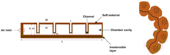
Figure 4.
Principle of the soft bending actuator used as Pneunets. (Left): The different components of the actuator with some specific parameters, including (h) height of the cavity, (H) height of the whole actuator, (w) width of the cavity, (W) width of the whole chamber, (n) height of the channel, (L) length of the whole actuator, (l) distance between two chambers, and (t) thickness of the bottom layer. (Right): Configuration when actuated. Using pressurized air, the actuator’s inner cavities tend to inflate in all directions. Due to the inextensible layer, the length of the finger is constrained on both sides, allowing it to bend and to deflect to its normal direction, allowing the bottom wall to inflate.
2.3. Finite Element Analysis
Finite element analysis (FEA) is a powerful computational tool used to simulate the behavior of complex engineering systems, such as the soft non-linear material that is under study here. It is widely used in engineering design and optimization to predict how structures and materials will perform under various loads and conditions. In the context of soft bending pneumatic actuators, FEA is crucial for understanding their behavior and optimizing their design. Indeed, one can test different design parameters, such as the thickness and shape of the actuator, and optimize their performance for specific applications.
2.3.1. Abaqus Inputs
A finite element analysis was conducted using Abaqus−Computer-aided engineering option to simulate various CAD models designed in Autodesk Inventor (Inventor 2022 Professional, Autodesk, San Francisco, CA, USA). The objective was to understand how the models behave using different material properties and validate the chosen design after fabrication and molding. The model that best meets the requirements specified in Table 1 will be selected for testing and validation.
The assembly model was divided into five parts, including one top part with chambers and a channel, two bottom parts to close the top part, defining the non-extensible layer at the junction of two surfaces, and two PLA strips attached to the bottom of the actuator. The top and two bottom parts were assigned as solids with hyperelastic properties, while the intersection of the two surfaces of both bottom parts and the intersection between the PLA strip and the second bottom layer were defined as a shell with a thickness of 0.1 mm. The hyperelastic properties were determined using coefficients calculated in the study by Marechal [22], which employed, amongst others, the Yeoh model as a hyperelastic constitutive model to describe the mechanical behavior of soft materials. This model is widely used due to its accuracy with a limited number of coefficients and is used in this manuscript as well. The strain energy function of the Yeoh model for incompressible material can be written as the following Equation (1):
where is the first principal invariant of the strain tensor and , , and are material parameters that can be determined experimentally.
Some of the soft materials that were examined in the finite element analysis software as well as the material properties for PLA and the fabric are presented in summary form within Table 2.
Table 2.
Mechanical properties of the PLA, the fabric, and example of soft materials used for testing on Abaqus.
Regarding the loads, gravitational forces directed downwards on the actuator and the uniform pressure expanding inside the chambers were defined. Moreover, contact interaction between adjacent chambers was defined to make the simulation as realistic as possible. Finally, one end of the actuator was entirely constrained in all directions to simulate the experiment where the actuator hangs vertically against gravity without falling.
Each model simulated in ABAQUS has its own parametric changes from the material to geometrical parameters such as the height of the chambers, the thickness of the lateral walls, the number of chambers in the actuator to study their influence on the bending, and also the pressure needs, as well as the amount of inflation of the chambers.
2.3.2. Data Acquisition and Post-Processing
The outputs obtained from the simulation were processed using Matlab (Matlab 2021b, Mathworks, Natick, MA, USA) to find the design that gives the required bending angle, pressure, material compliance, and inflation of the chambers.
- Bending angle: To characterize the bending angle, the displacement over time of 2 nodes, located at each end of the actuator, was monitored from 0 kPa to the desired pressure. Using the vector in the initial state and the vector in the final state , where O is the origin of the vector, the coordinate of the point at the tip of the actuator in the initial state, and A the coordinate of the node at the other end of the actuator in the final state (see Figure 2), the bending angle was calculated according to the following Equation (2):
- Inflation of the bottom wall of the chambers: The calculation is analogous to that of the bending angle. However, in this case, we monitored the displacement of the node located at the middle of the designated chamber’s bottom wall (indicated by a red dot in Figure 5). As the inflation does not act along a single axis (the actuator is bending and deforming in the XY plane, which is defined by the plane formed by the points O, , and A in Figure 2, with Z being perpendicular to this plane and pointing towards the reader), the coordinates of the top and the bottom walls were monitored to compute the norm of the vector created from both coordinates independently of the actuator’s orientation.
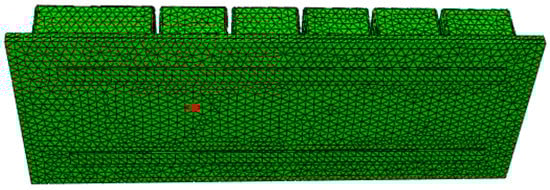 Figure 5. The inflation of the first chamber’s bottom wall was monitored by measuring the displacement of the node (indicated by the red dot). The node was chosen at the middle of one of the chambers to represent the maximum deflection of the bottom wall and to assess the actuator’s capability to interact with the soft tissues of the user wearing the robotic rehabilitation or exoskeleton.
2.4. Fabrication of the Soft Bending Actuator
After identifying a model that closely satisfies the requirements specified in Table 1, the fabrication process takes place. The actuator was cast in 3D-printed PLA molds (Ultimaker B.V., Utrecht, The Netherlands), as depicted in Figure 6. An exploded view of the different molds can be seen in Figure 7. The molds were divided into two parts: a top mold to create the PneuNets and chambers, and a bottom mold to close the actuator and insert the fabric layer and PLA strips. After printing, the soft material Ecoflex 00−30 (Smooth−on, Macungie, PA, USA), that was chosen as the soft material since it meets best the requirements defined (see Section 3.1), was mixed for 3 min using the two parts A and B with a ratio of 1:1 according to the datasheet. After the two silicone parts were mixed, the mixture was placed in a vacuum chamber for 10 to 15 min to remove excessive air bubbles that could create weak spots in the design. Afterward, the silicone was poured into the top mold as the first step and placed in an oven at around 50 °C to decrease the curing time by half (2 h instead of 4 h). The reason we did not go higher in temperature is that the maximum allowed temperature for the PLA molds is approximately 50 °C, limiting our range of temperature for good operation. Whenever the top mold was cured, the same process was performed for the bottom mold. As an additional step, the pouring process included the insertion of the PLA strips after a first layer of Ecoflex 00−30 was applied to the bottom mold, and the insertion of the fabric after a second layer of Ecoflex 00−30 was poured above the PLA strips. Finally, the top mold part was assembled with the bottom part after adding a third and last layer of silicone above the fabric with again a heat treatment to speed up the curing process.
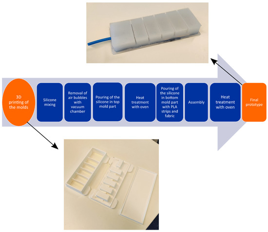
Figure 6.
Fabrication procedure of the PneuNets. The actuator was cast in 3D-printed PLA molds, with the molds comprising a top mold for creating PneuNets and chambers and a bottom mold for closing the actuator and inserting the fabric layer and PLA strips. Ecoflex 00−30 was mixed for 3 min with the two parts A and B in a ratio of 1:1. After proper mixing, the mixture was placed in a vacuum chamber for 10 to 15 min to remove air bubbles. Subsequently, the silicone was poured into the top mold, followed by curing in an oven at 50 °C to reduce the curing time to 2 h. The same process was repeated for the bottom mold, including the insertion of PLA strips and fabric layers. Finally, the top mold was assembled with the bottom mold, with a third layer of silicone added above the fabric with last heat treatment process.
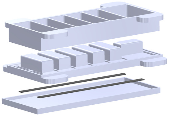
Figure 7.
Exploded view of the different CAD molds to fabricate the PneuNets. From top to bottom: the two first parts are meant to shape the PneuNets chambers and cavities. The third part is the PLA strips and the fourth part is the bottom mold to completely seal the PneuNets from the bottom and especially insert the fabric and PLA strips.
2.5. Experimental Protocol of the Designated Actuator
The purpose of the experimental protocol is to determine whether the soft actuator designed in the Abaqus simulation environment matches the real model. To achieve this, a test bench similar to the one presented by Ferrentino et al. [23] was built, which enables controlling the inner pressure and the characterization of the actuator using motion tracking (Figure 8) thanks to an RGBD camera installed to track the position of red markers on the actuator during bending (Number 1 in Figure 8). The test bench consists of a 3−way proportional pressure regulator VEAB−L−26−D7−Q4−A4−1R1 (Festo, Esslingen am Neckar, Germany—Number 3) where the inlet is connected to compressed air available in the lab and where the outlet is connected to the actuator (Number 4) with a PCB (Number 2 in Figure 8). The PCB serves to control the valve, which is equipped with a pressure sensor that is monitored by the PCB. The primary function of the PCB is to regulate the setpoint of the pressure, thereby determining the pressure–time profile to be applied. The actuator is hanging from a 3D-printed interface attached to a plexiglass box measuring 30 cm × 50 cm × 50 cm. The FEA model, which includes the Yeoh model, was validated by comparing the position of the markers on the actuator with the selected nodes in the FEA simulation and by calculating the bending angle between them. To estimate the position of the markers, the camera was first calibrated using the Zhang calibration method [23], after which the images from the camera were processed through a segmentation algorithm that highlights the red markers in white against a black background. The resulting frames were then sent to a clustering algorithm, which recognizes the number of markers on the pneumatic actuator and calculates their centroid positions using the camera calibration.
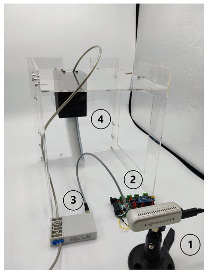
Figure 8.
The experimental setup. (1) An RGBD camera used to track the red markers drawn on the side of the actuator and deduced bending angle; (2) a PCB to control the valve; (3) a 3−way proportional pressure regulator where the inlet pressure is converted to a desired outlet pressure; (4) the actuator attached to an interface to check the validity of the FEA.
3. Results
3.1. FEM Results
Multiple sets of different parameters were tested in Abaqus by varying the number of chambers, the geometry of the PneuNets (as shown in Figure 4), and the material, while keeping the properties of PLA and fabric and the overall length and width of the actuator constant. The results of the FEM using Abaqus are shown in Figure 9. These results were obtained with the Ecoflex 00−30 material at a total pressure of 15 kPa and using five effective chambers to achieve the closest bending possible as defined in the requirements without exceeding the pressure threshold in Table 1. Note that the first chamber, where the boundary conditions have been defined, only serves the purpose of inserting the tube as an inlet for the fabrication process and does not influence the bending performance. Although the PLA strips and fabric support the major stresses in the design, their stress limits are not exceeded.
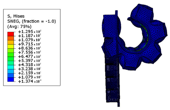
Figure 9.
The results of the final design in Abaqus at 15 kPa indicate that the actuator exhibits good performance under required pressure. The simulation was conducted using Ecoflex 00−30 as the soft material, PLA for the strips, and fabric for the inextensible layer. The simulation ran from 0 to 15 kPa and showed that the actuator is capable of withstanding pressure, with good resistance observed in the chambers on one side, as well as the PLA strips and the fabric layer. These findings suggest that the actuator is suitable for use in active strapping procedure.
3.1.1. Bending Performance
Figure 10 shows the bending performance of the actuator using Equation (2) with a pressure of 15 kPa that increases linearly over time. At the beginning of the simulation, where there is no pressure in the system, the actuator bends due to the effects of gravity and its own weight, along with its hyperelastic properties. Next, a linearly increasing pressure is applied to actively bend the actuator. The actuator exhibits a linear response within the pressure range of 0 to 5 kPa, which is attributed to the predominance of PLA over the actuator’s bending behavior. However, for pressures beyond this range, the actuator shows a non-linear response due to the compliant behavior taking over the PLA strips. The maximum bending angle obtained from the FEM simulation is 150 degrees, which is sufficient to enclose the limb in the configuration proposed in Figure 3.
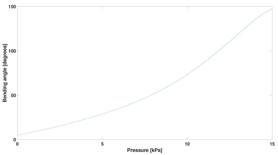
Figure 10.
Bending angle retrieved after post-processing in Matlab. The behavior of the actuator shows a linear response from 0 to 5 kPa explained by the dominance of the PLA over the bending behavior of the actuator and a non-linear response for remaining pressure explaining the compliant behavior taking over the PLA strips. The maximum bending of the actuator reaches 150°.
3.1.2. Bottom Wall Inflation
Figure 11 shows the inflation of the bottom wall using the method explained in Section 2.3.2, which is meant to be in contact with the soft tissues. Naturally, compared to the bending angle where there was an initial bending effect with no pressure, there is no inflation when no pressure is applied. When applying pressure, the bottom wall inflates until 1.4 cm, which is enough to efficiently compress the soft tissues. The approximated linear behavior of the inflation, without any plateau at high pressure, suggests that the bottom layer still has room for further deflection, potentially allowing for higher pressure demands. This inflation is a crucial outcome of the design as it determines the interaction of the actuator with the soft tissues of the user, as shown in Figure 3. High inflations can lead to popping out the PLA strips and the fabric layer located at the bottom of the actuator as well, whereas too low inflation may not interact sufficiently with the user’s soft tissues.
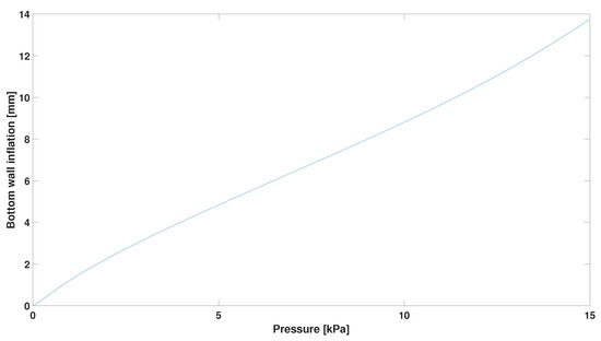
Figure 11.
Bottom wall inflation retrieved after post-processing in Matlab. The results indicate that, at 15 kPa, the maximum inflation is 1.4 cm. The approximated linear behavior of the inflation suggests that the bottom layer can still deflect further, allowing for higher-pressure demands. This is crucial for the actuator’s interaction with the user’s soft tissues. High inflations can pop out the PLA strips and fabric layer, whereas low inflation may not sufficiently interact with the soft tissues.
According to the results seen in Figure 9, Figure 10 and Figure 11, the design meeting all requirements is the one with parameters summarized in Table 3. This set of parameters allows us to achieve the requirements defined in Table 1 in terms of bending performance, pressure need, and constraints for geometry.
Table 3.
Final parameters used for validation following parameters defined in Figure 4.
3.2. Experimental Results
3.2.1. Bending Performance
Figure 12 displays the final configuration of the actuator at 15 kPa, captured by the RGB camera to detect and isolate the red dots in order to determine the bending angle. The experimental conditions encompassed quasi-static conditions for the whole experiment. Quasi-static conditions promote stability and safety in our design by neglecting dynamic effects and simplifying analysis through the assumption of slow changes, in contrast to transient behavior. The resemblance in the behavior between Figure 9 and Figure 12 is noticeable. The PLA strips and fabric layer can withstand the stresses created from the bending motion, as shown by the simulation.
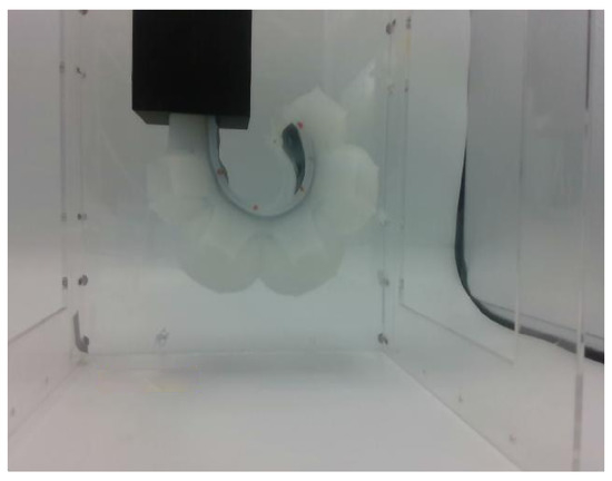
Figure 12.
Maximum bending obtained with our strap by inflating with 15 kPa. The RGB camera detects the red dots at the side of the actuator and allows for computing the bending angle. The PLA strips and the fabric demonstrate good endurance against the stresses generated from the bending motion, as confirmed by the simulation results.
As per the simulation, the pressure, depicted in blue, rises linearly from 0 to 15 kPa in 60 s resulting in a rate of 0.25 kPa/s as shown in Figure 13. The bending angle in red begins gradually, similar to the pressure response. A noticeable response time can be observed at the beginning of the experiment, likely due to possible friction inside the tube connecting the air source to the actuator and the opening of the valves. Following this initial response time, the controller successfully achieves a controlled linear flow rate. Subsequently, the bending angle intensifies as the pressure steadily increases over time.
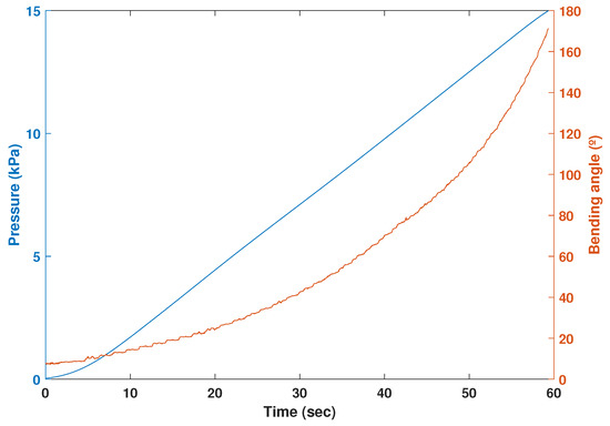
Figure 13.
The temporal progression of both pressure and bending angle. The bending angle, in red, initiates in a gradual manner, exhibiting a similar pattern to the response of the pressure, in blue. At the beginning of the experiment, an initial response time becomes evident, which is likely attributed to potential friction within the tube that links the air source to the actuator, as well as the opening of the valves. After this initial response time, the controller effectively achieves a controlled linear flow rate. Consequently, the bending angle amplifies as the pressure gradually and consistently rises over the course of time.
3.2.2. Bottom Wall Inflation
As shown in Figure 14 and as expected, when the actuator is pressurized, the air not only deforms the chambers to create a bending effect, but also applies pressure to the bottom wall of the actuator, where they will interact with soft tissues of the user’s arm when inserted into the physical interface. Moreover, the PLA strips appear to not conflict with the inflation of the bottom wall if properly placed. Finally, the hypothesis presented in Section 2.2 regarding the fabric layer at the bottom of the actuator, which allows for stiffness along its length and compliance in its normal direction, was confirmed by the simulation results and once again during the experiment.
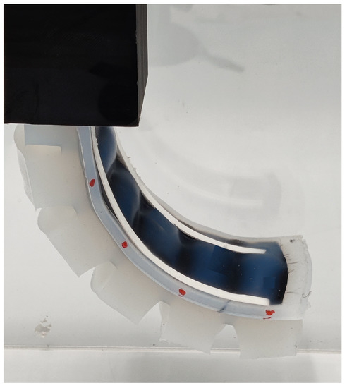
Figure 14.
Inflation obtained for the bottom walls. On one hand, PLA does not interfere with the inflation of the bottom wall. On the other hand, the hypothesis relating the fabric layer located at the bottom of the actuator, which enables stiffness along its length while exhibiting compliance in its normal direction, was verified by both the simulation outcomes and the experimental results.
3.2.3. Comparison between Simulation and Experiment
Figure 15 shows the differences in terms of bending angles between the simulation performed in Abaqus and the experimental data computed, both using Equation (2). The data were low pass filtered to cut out high-frequency image processing noises. The real model has nearly the same initial bending angle as the simulation and has a final bending angle at 15 kPa of 167°. Since the root mean square error between the simulation and experiment could not be found directly (both curves have different sample sizes), the curve fitting tool from Matlab was first used to fit each curve and then to compare these two fitting curves to extract the root mean square error. Quantitatively, the simulation data show great fitness in terms of bending angles, with a root mean square error of 3.4°. The observed discrepancies between the simulation and experimental data, particularly between the 10–15 kPa range, can be attributed to the tendency of the PLA strips to rip the Ecoflex after multiple cycles, leading to changes in the bending angle behavior. Additionally, after several cycles, the PLA strips have a propensity to shift slightly from their original position toward the outside, which further alters the bending capability of the actuators. Furthermore, the observed differences between the bending angles retrieved from the real and simulation models can be attributed to the non-identical positioning of the red dots.
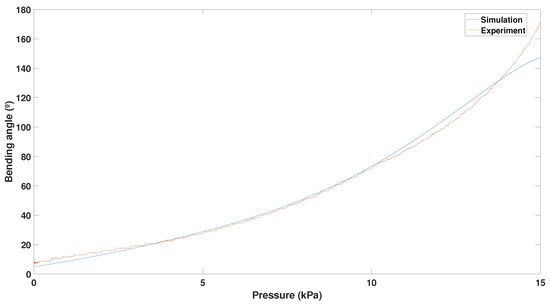
Figure 15.
Comparison between the experimentally obtained and simulated bending angles of the PneuNets is presented. The root mean square error between the two is 3.4°, which was obtained by fitting two curves and comparing them quantitatively to obtain the errors. The disparities between simulation and experimental data, particularly in the 10–15 kPa range, result from PLA strip tearing in Ecoflex after multiple cycles, altering bending angles. Additionally, the PLA strips shift slightly outward after several cycles, further impacting actuator bending. Differences in bending angles between real-world and simulation models stem from varying red dot positioning.
4. Discussion and Future Works
The strapping procedure is a critical aspect that ensures both comfort and safety within the physical interface of exoskeletons and rehabilitation robots. Undoubtedly, the process of attaching the physical interface necessitates a certain degree of skills and experiences from therapists, which may be both costly and impractical in the long term. This presents a significant obstacle for individuals with motor disabilities, who encounter difficulty in donning the straps and adjusting their tightness due to their motor limitations or sensory impairment. Although a few active physical interfaces exist, almost none of them have proposed a closing system to be implemented in rehabilitation robots. Moreover, the potential of soft actuators has been evaluated in terms of comfort, flexibility, and low weight, among others, but their potential remains underexplored for rehabilitation robotics employing a physical interface. This paper demonstrates that a strapping system using soft pneumatic actuators could be a promising solution for the automated donning and doffing of exoskeletons and other wearables.
Indeed, in this paper, we contributed to designing a new way to attach users to a robot for rehabilitation purposes using soft bending pneumatic actuators. Multiple simulations were performed to find a design that achieves the requirements defined at the beginning of the study, where the geometry with different parameters was investigated. The pressure of 15 kPa required to actuate the soft strap is notably low for achieving the target bending angles ranging between 145° and 180°. Regarding the strain and deformation during actuation, the actuators demonstrate high compliance in the chambers to deflect and generate the bending behavior of the strap, creating bulges in the bottom walls that are significant for interacting with the user’s soft tissues. Additionally, the number of chambers in the designed actuator was minimized to maximize the interaction area between the actuator and the soft tissues.
After selecting the most promising design based on the simulations run in Abaqus, an experimental protocol was carried out. While we were able to run simulations to investigate the bottom wall inflation, we were not able to obtain experimental data using the proposed protocol. Nevertheless, we plan to conduct further experiments with healthy users to better understand the interaction between the straps and the users. Concerning the bending angle, a root mean square error of 3.4° was reached, which shows a good correlation between the simulation and experiment. The main factors that explain some discrepancy between the simulation and experimental data, especially between 10 and 15 kPa, come from the fact that the PLA strips, after different cycles, rip the Ecoflex and then change the behavior of the bending angle. Moreover, the PLA strips have the tendency after several cycles to slightly migrate from their initial position toward the outside, again changing the behavior of the actuators’ bending capability. These can be alleviated by adding extra Ecoflex where higher-pressure zones can be found in the simulation environment (see Figure 9, where the stresses are depicted at the level of the PLA strips). Another solution is to investigate the use of other material with a high tensile stiffness but low bending stiffness, such as wires. The red dots used to retrieve the bending angle from the real and simulation models are not located at exactly the same position, which explains some differences, particularly near 15 kPa.
In this manuscript, we also chose an arbitrary pressure rate of 0.25 kPa/s increasing in a linear way. However, one critical consideration pertains to the response time of these actuators, which could significantly influence their performance. Factors such as material compliance, viscoelasticity, and flow rate contribute to the actuator’s finite response time. When subjected to rapid pressure variations, the actuator may experience limitations in instant adaptation and complete responsiveness to the changes. Consequently, a temporal delay can arise between the applied pressure and the subsequent bending motion, leading to deviations from the desired response. In addition to response time, rapid pressure variations can induce pressure losses within the actuator due to factors such as fluid leakage or flow dynamics. These losses can detrimentally affect the overall performance and stability of the actuator. To mitigate these effects, it is essential to consider appropriate sealing techniques and implement effective fluid control mechanisms, ensuring consistent and reliable actuation.
As for the length of the straps, a length of 17.4 cm was used as a basis for the design, representing the 95th percentile of the upper arm circumference. While this length represents most arms, it may be necessary to define other lengths to fit the 95th percentile population that could use the active straps. One solution could be to define the range of arm circumference and normalize it for each range (small, medium, large). Another solution is to add a customized solution where every user could inherit a personalized physical interface with customized straps, since the concept can be easily scaled for different circumferences. Additionally, the defined circumference is taken for healthy users and may not be relevant for patients needing rehabilitation therapy. In the case of arm impairment, the biceps brachii will be atrophied due to the lack of muscle involvement. As cost-effective and easily manufacturable materials were used, the production of individualized straps for each patient would be a feasible task.
Future works will be dedicated to implementing the active straps designed for healthy users to investigate the effect of constant pressure in a first step and see whether the active straps hold the user inside the interface. With this path, we envision using the automatic enclosing system and strapping pressure combined with the pressure monitored inside a customized interface [24]. Indeed, to assess comfort and safety during rehabilitation, it is common to monitor the pressure on soft tissues inside the physical interface. As part of our future work, we plan to investigate locking mechanisms or materials that can effectively secure the strap once it has been wrapped around the arm. This can include exploring the use of a vacuum-based mechanism such as layer jamming to actively change stiffness or other advanced mechanisms that provide reliable and secure attachment [25,26]. By studying and implementing such mechanisms, we can enhance the overall functionality and usability of the soft bending actuator. These investigations will contribute to the development of more advanced and robust solutions for securing the strap in future iterations of the actuator design.
5. Conclusions
In this paper, we designed a soft bending pneumatic actuator to automatically enclose the upper limb of a user. To achieve this, we utilized 3D-printing and molding techniques, drawing inspiration from existing designs such as PneuNets. We performed a complete analysis using finite element analysis in Abaqus to determine the optimal design for our purposes. The bending angle in the simulation reached 150° and, for the experimental data, 167°, with an accuracy of 3.4° root mean square error. These results indicate that our strap model and simulation were successfully developed to meet the specific requirements of our application. The potential advantages of soft bending pneumatic actuators in strapping procedures includes user comfort and safety. Future research could lead to the development of more effective and safe strapping interfaces in wearable robotics, thereby improving the overall performance of these devices and increasing user acceptance.
Author Contributions
Conceptualization, C.v.V., K.L. and T.V.; methodology, C.v.V. and K.L.; software, C.v.V. and P.F.; validation, C.v.V., E.R. and P.F.; formal analysis, C.v.V.; investigation, C.v.V.; resources, T.V. and B.V.; data curation, C.v.V.; writing—original draft preparation, C.v.V.; writing—review and editing, C.v.V., E.R., P.F., F.B.-M., K.L., B.V. and T.V.; visualization, C.v.V.; supervision, T.V.; project administration, T.V.; funding acquisition, T.V. All authors have read and agreed to the published version of the manuscript.
Funding
This research was funded by the Research Council from Vrije Universiteit Brussel (OZR) with grant numbers OZR4007, IRP10_b and by the Federal Public Service Policy & Support (FOD BOSA) with grant number AI_2022_VUB-AI-005. Ellen Roels is a FWO-SB fellow of the Research Foundation-Flanders (FWO) with FWO grant 1S84120N. Kevin Langlois is a postdoctoral fellow of the Research Foundation Flanders (FWO) with FWO grant 1258523N.
Data Availability Statement
The data presented in this study are available on request from the corresponding author.
Conflicts of Interest
The authors declare no conflict of interest.
References
- Young, A.J.; Ferris, D.P. State of the Art and Future Directions for Lower Limb Robotic Exoskeletons. IEEE Trans. Neural Syst. Rehabil. Eng. 2017, 25, 171–182. [Google Scholar] [CrossRef] [PubMed]
- Lenzi, T.; Vitiello, N.; Rossi, S.M.M.D.; Persichetti, A.; Giovacchini, F.; Roccella, S.; Vecchi, F.; Carrozza, M.C. Measuring human–robot interaction on wearable robots: A distributed approach. Mechatronics 2011, 21, 1123–1131. [Google Scholar] [CrossRef]
- He, Y.; Eguren, D.; Luu, T.P.; Contreras-Vidal, J.L. Risk management and regulations for lower limb medical exoskeletons: A review. Med. Devices 2017, 10, 89–107. [Google Scholar] [CrossRef] [PubMed]
- Bessler, J.; Schaake, L.; Kelder, R.; Buurke, J.H.; Prange-Lasonder, G.B. Prototype Measuring Device for Assessing Interaction Forces between Human Limbs and Rehabilitation Robots—A Proof of Concept Study. In Proceedings of the 2019 IEEE 16th International Conference on Rehabilitation Robotics (ICORR), Toronto, ON, Canada, 24–28 June 2019; pp. 1109–1114. [Google Scholar]
- Langlois, K.; Moltedo, M.; Bacek, T.; Rodriguez-Guerrero, C.; Vanderborght, B.; Lefeber, D. Design and Development of Customized Physical Interfaces to Reduce Relative Motion Between the User and a Powered Ankle Foot Exoskeleton. In Proceedings of the 2018 7th IEEE International Conference on Biomedical Robotics and Biomechatronics (Biorob), Enschede, The Netherlands, 26–29 August 2018; pp. 1083–1088. [Google Scholar]
- Gorgey, A.S. Robotic exoskeletons: The current pros and cons. World J. Orthop. 2018, 9, 112–119. [Google Scholar] [CrossRef]
- Langlois, K.; Rodriguez-Cianca, D.; Serrien, B.; De Winter, J.; Verstraten, T.; Rodriguez-Guerrero, C.; Vanderborght, B.; Lefeber, D. Investigating the Effects of Strapping Pressure on Human-Robot Interface Dynamics Using a Soft Robotic Cuff. IEEE Trans. Med. Robot. Bionics 2021, 3, 146–155. [Google Scholar] [CrossRef]
- Hasegawa, Y.; Tayama, M.; Saito, T.; Sankai, Y. Active air mat for comfortable and easy to wear a forearm support system. In Proceedings of the 2011 IEEE/RSJ International Conference on Intelligent Robots and Systems, San Francisco, CA, USA, 25–30 September 2011; pp. 4899–4904. [Google Scholar]
- Yang, S.T.; Ryu, J.W.; Park, S.H.; Lee, Y.B.; Koo, S.H.; Park, Y.L.; Lee, G. An active compression sleeve with variable pressure levels using a wire-fabric mechanism and a soft sensor. Smart Mater. Struct. 2019, 28, 114002. [Google Scholar] [CrossRef]
- Hasegawa, Y.; Hasegawa, T.; Eguchi, K. Pneumatic tubular body fixture for wearable assistive device—Analysis and design of active cuff to hold upper limb—. In Proceedings of the 2014 IEEE/RSJ International Conference on Intelligent Robots and Systems, Chicago, IL, USA, 14–18 September 2014; pp. 2140–2145. [Google Scholar]
- Abidi, H.; Cianchetti, M. On Intrinsic Safety of Soft Robots. Front. Robot. AI 2017, 4, 5. [Google Scholar] [CrossRef]
- Kandasamy, S.; Teo, M.; Ravichandran, N.; McDaid, A.; Jayaraman, K.; Aw, K. Body-Powered and Portable Soft Hydraulic Actuators as Prosthetic Hands. Robotics 2022, 11, 71. [Google Scholar] [CrossRef]
- Xavier, M.S.; Tawk, C.D.; Zolfagharian, A.; Pinskier, J.; Howard, D.; Young, T.; Lai, J.; Harrison, S.M.; Yong, Y.K.; Bodaghi, M.; et al. Soft Pneumatic Actuators: A Review of Design, Fabrication, Modeling, Sensing, Control and Applications. IEEE Access 2022, 10, 59442–59485. [Google Scholar] [CrossRef]
- Polygerinos, P.; Lyne, S.; Wang, Z.; Nicolini, L.F.; Mosadegh, B.; Whitesides, G.M.; Walsh, C.J. Towards a soft pneumatic glove for hand rehabilitation. In Proceedings of the 2013 IEEE/RSJ International Conference on Intelligent Robots and Systems, Tokyo, Japan, 3–7 November 2013; pp. 1512–1517. [Google Scholar]
- Pan, M.; Yuan, C.; Liang, X.; Dong, T.; Liu, T.; Zhang, J.; Zou, J.; Yang, H.; Bowen, C. Soft Actuators and Robotic Devices for Rehabilitation and Assistance. Adv. Intell. Syst. 2022, 4, 2100140. [Google Scholar] [CrossRef]
- Ilievski, F.; Mazzeo, A.D.; Shepherd, R.F.; Chen, X.; Whitesides, G.M. Soft Robotics for Chemists. Angew. Chem. Int. Ed. 2011, 50, 1890–1895. [Google Scholar] [CrossRef] [PubMed]
- Wang, J.; Fei, Y.; Pang, W. Design, Modeling, and Testing of a Soft Pneumatic Glove With Segmented PneuNets Bending Actuators. IEEE/ASME Trans. Mechatron. 2019, 24, 990–1001. [Google Scholar] [CrossRef]
- Ferrentino, P.; Roels, E.; Brancart, J.; Terryn, S.; Van Assche, G.; Vanderborght, B. Finite Element Analysis-Based Soft Robotic Modeling: Simulating a Soft Actuator in SOFA. IEEE Robot. Autom. Mag. 2023, 2–12. [Google Scholar] [CrossRef]
- Bishop, C.W.; Bowen, P.E.; Ritchey, S.J. Norms for nutritional assessment of American adults by upper arm anthropometry. Am. J. Clin. Nutr. 1981, 34, 2530–2539. [Google Scholar] [CrossRef]
- Terryn, S.; Roels, E.; Brancart, J.; Van Assche, G.; Vanderborght, B. Self-Healing and High Interfacial Strength in Multi-Material Soft Pneumatic Robots via Reversible Diels–Alder Bonds. Actuators 2020, 9, 34. [Google Scholar] [CrossRef]
- Dubrovski, P.; Čebašek, P. Analysis of the mechanical properties of woven and nonwoven fabrics as an integral part of compound fabrics. Fibres Text. East. Eur. 2005, 13, 50–53. [Google Scholar]
- Marechal, L.; Balland, P.; Lindenroth, L.; Petrou, F.; Kontovounisios, C.; Bello, F. Toward a Common Framework and Database of Materials for Soft Robotics. Soft Robot. 2021, 8, 284–297. [Google Scholar] [CrossRef]
- Ferrentino, P.; Tabrizian, S.K.; Brancart, J.; Assche, G.V.; Vanderborght, B.; Terryn, S. FEA-Based Inverse Kinematic Control: Hyperelastic Material Characterization of Self-Healing Soft Robots. IEEE Robot. Autom. Mag. 2022, 29, 78–88. [Google Scholar] [CrossRef]
- Langlois, K.; Roels, E.; Van De Velde, G.; Espadinha, C.; Van Vlerken, C.; Verstraten, T.; Vanderborght, B.; Lefeber, D. Integration of 3D Printed Flexible Pressure Sensors into Physical Interfaces for Wearable Robots. Sensors 2021, 21, 2157. [Google Scholar] [CrossRef]
- Plooij, M.; Mathijssen, G.; Cherelle, P.; Lefeber, D.; Vanderborght, B. Lock Your Robot: A Review of Locking Devices in Robotics. IEEE Robot. Autom. Mag. 2015, 22, 106–117. [Google Scholar] [CrossRef]
- Narang, Y.S.; Vlassak, J.J.; Howe, R.D. Mechanically Versatile Soft Machines through Laminar Jamming. Adv. Funct. Mater. 2018, 28, 1707136. [Google Scholar] [CrossRef]


Disclaimer/Publisher’s Note: The statements, opinions and data contained in all publications are solely those of the individual author(s) and contributor(s) and not of MDPI and/or the editor(s). MDPI and/or the editor(s) disclaim responsibility for any injury to people or property resulting from any ideas, methods, instructions or products referred to in the content. |
© 2023 by the authors. Licensee MDPI, Basel, Switzerland. This article is an open access article distributed under the terms and conditions of the Creative Commons Attribution (CC BY) license (https://creativecommons.org/licenses/by/4.0/).