Abstract
In this paper, a new socially assistive robot (SARs) called HBS-1.2 is presented, which uses 6-ply twisted and coiled polymer (TCP) artificial muscles in its hand to perform physical tasks. The utilization of 6-ply TCP artificial muscles in a humanoid robot hand is a pioneering advancement, offering cost effective, lightweight, and compact solution for SARs. The robot is designed to provide safer human–robot interaction (HRI) while performing physical tasks. The paper explains the procedures for fabrication and testing of the 6-ply TCP artificial muscles, along with improving the actuation response by using a Proportional-Integral-Derivative (PID) control method. Notably, the robot successfully performed a vision-based pick and place experiment, showing its potential for use in homecare and other settings to assist patients who suffer from neurological diseases like Alzheimer’s disease. The study also found an optimal light intensity range between 34 to 108 lumens/m2, which ensures minimal variation in calculated distance with 95% confidence intervals for robust performance from the vison system. The findings of this study have important implications for the development of affordable and accessible robotic systems to support elderly patients with dementia, and future research should focus on further improving the use of TCP actuators in robotics.
1. Introduction
The field of robotics has experienced significant growth in recent years, particularly in the area of elderly patient care. With a rising number of elderly patients requiring care, there is an increasing demand for dementia care services [1,2]. As shown in Figure 1, the number of Americans aged 65 and older with Alzheimer’s disease is projected to grow from the current estimated prevalence of 6.2 million in 2021 up to 13.8 million by 2060 [1]. However, the caregiving workforce is diminishing, and most elderly care in the US is provided by informal and unpaid caregivers [3,4]. This care is valued at nearly $256.7 billion, but this cost extends to the family in the form of caregivers’ increased risk for emotional distress and negative effects on mental and physical health [2]. In response, socially assistive robots (SARs) have emerged as a promising solution to support caregivers and healthcare workers in providing care services to patients [5]. SARs are humanoid robots designed to promote healthy cognitive and emotional health and support patients’ physical needs.

Figure 1.
Trend indicating an increase in number of patients suffering from Alzheimer’s Disease, Courtesy of CDC [1,2] Disclaimer: The materials, links, or information referenced in this journal paper, including any citations to the Centers for Disease Control and Prevention (CDC), or any other United States Government website, are used solely for informational purposes. The inclusion of these references does not constitute endorsement or recommendation by the U.S. Government, CDC, or any of its agencies.
To effectively provide health care services that complement health care workers and caregivers, SARs need to perform tasks that can assist elderly patients physically as well as support patients’ cognitive and emotional health. Although current humanoid robots such as Pepper [6], Stevie [7], Care-O-Bot [8] have advanced features to enable improved interactions with humans, they still have limitations for application in a home setting. While SARs can significantly reduce the workload of caregivers and healthcare workers, most current designs have limitations for home use with bulky and expensive DC motors that may intimidate patients. Park et al. [9] successfully demonstrated the use of assistive robots, with general purpose manipulators, as a meal assistant system to promote independent living for patients. However, it was noted that many patients felt intimidated by the large size of the robot and one participant also felt threatened by the thick arm approaching her in the beginning of evaluation for meal assistance. As a result, there is a need to create novel manipulator designs for SARs that enable robots to interact with humans in a more gentle, compliant, and safe manner, while also meeting the diverse requirements of patients. One area of innovation that shows promise in developing low-cost, lightweight, and compact manipulators for SARs is twisted coiled polymer (TCP) actuators.
Humanoid robots such as Buddy [10] and HBS-1 [11] have been designed and developed at the Humanoid, Biorobotics, and Smart systems (HBS) laboratory at UT Dallas, with the aim to make such systems more affordable by utilizing innovative methods of manufacturing, such as custom-made 3D printing and in house manufactured actuators. One of our goals for the robot is to develop it for use as a SAR to provide caregiver support for elderly patients with the intent to provide several benefits, listed in Figure 2, for patients and caregivers. The HBS-1.2 SAR integrates 6-ply TCP muscles in its robotic hand, replacing bulky and expensive servo motors to perform different tasks and actions. TCP muscles have significant benefits, including high force and actuation strain, lightweight, all polymer-based actuation, noise-free actuation, and high-energy density [12,13].These characteristics of TCP actuators, make them an attractive choice for developing soft robotic systems both on land and underwater. Their versatility and capabilities make them suitable for various applications, including crawling robots [14], underwater robotic systems such as robotic fish [15], and bio-inspired designs like robotic jellyfish [16,17,18]. In this article, we show the first-time implementation of 6-ply TCP muscles in a humanoid robot, demonstrating the benefits of TCP muscles for advancing robotic system development. An overview of the 6-ply TCP actuated robot, HBS-1.2, can be found in the Supplementary Video (Supplementary Materials) as well as via the following link: https://youtu.be/fO5xgZ2Z1hM, (accessed on 26 July 2023).
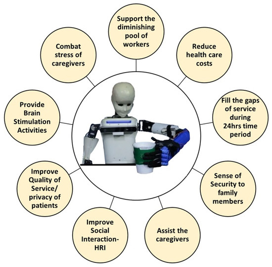
Figure 2.
Goals for HBS-1.2 to serve as SAR and provide various benefits to patients and caregivers.
In this study, we focus on developing a 6-ply TCP actuated robotic hand for use in SARs, examining the fabrication of the TCP actuator and its integration into a robotic hand. We also conduct experiments to test the performance of the TCP actuator in the robotic hand, including its ability to grasp an object. Although we do not integrate the TCP actuator with a PID control system into a robotic arm, we have created and tested both systems independently in this study, providing a foundation for further investigations in this field. The development of TCP actuated robotic hands holds significant implications for the creation of lightweight and flexible manipulators in SARs, particularly with regard to ensuring safer physical interaction between humans and robots in the context of providing care services to elderly patients.
The study is structured into multiple sections, with each section exploring distinct aspects of the design and development of the robot. In Section 2, the fabrication of TCP actuators is presented, along with the investigation of PID control for 6-ply TCP actuators through standalone experiments. Section 3 highlights the implementation of 6-ply TCP actuators in the robotic hand, followed by testing 6-ply TCP actuators in the robot with a vision-assisted pick and place experiment. In Section 4, important aspects in developing SARs are discussed, along with the presentation of survey results conducted at UT Dallas regarding the requirements of a SAR. Finally, Section 5 provides a summary of the study’s findings and concludes the work.
2. Fabrication and Implementation of TCP Actuators in a Robotic Hand
2.1. Fabrication, Annealing, and Training Methods for TCP Actuators: An Overview
The TCP muscles for the robotic hand are fabricated by a process of twisting and coiling of the nylon polymer thread. To fabricate a 6-ply TCP muscle, three threads of equal lengths are needed. To fabricate a muscle of length L, the initial length of the selected threads must be approximately six times the required length (L). The threads are initially suspended vertically by securing one end of the threads to a DC motor and suspending weights at the other end. The weight needed and the speed of the DC motor is finalized based on recommendations from our related works [11,19,20]. Three nylon polymer threads of diameter 0.2 mm [21] each are securely tied to the DC motor to twist the fibers together, and a weight of 525 g is suspended on the other end, as shown in Figure 3.
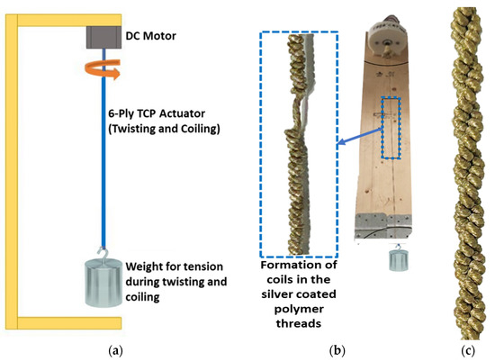
Figure 3.
(a) Schematic of fabrication setup (b) Fabrication setup for the 6-ply TCP actuators (c) Fabricated 6-Ply TCP actuator.
During fabrication, it must always be ensured that the spirals of each individual thread fibers from the spool are oriented in the same direction, and that the DC motor rotates in the same direction as thread spirals to form the new coil. This is an important aspect of fabrication to ensure successful formation of the 6-ply TCP muscles, which can provide consistent performance. Continuous twisting of fibers eventually leads to self-coiling of the threads resulting in the formation of a coiled structure. The coiled polymer is carefully allowed to coil itself again from the middle to form the stable structure. Since this fabrication is a cold working process, it induces stress in the muscle. To release stress, annealing is carried out, which increases durability and improves muscle actuation consistency [16,21]. The complete setup and process for fabrication and annealing of the artificial muscles is provided as the Supplementary File. This process makes the muscle smooth and trains it to become electro-thermally active. This training procedure also improves the strain rate and therefore leads to a higher number of lifecycles the muscle can withstand. Based on this annealing and training of the 6-Ply TCP muscle, the maximum strain rate was found to be around 5% at 8 V input voltage and 2.2 A current for 20 s heating time.
2.2. A Study of 6-Ply TCP Actuator Properties and Performance
To obtain a deeper understanding of the behavior of the 6-ply TCP muscle, new TCP muscles were fabricated and characterized in a standalone setup without being integrated into the hand with results shown in Figure 4.
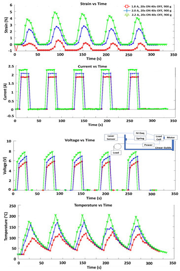
Figure 4.
Force and displacement of the TCP muscle under different weights for 6.5 V, 7.5 V, and 8.5 V.
Characterization tests were performed for 150 mm long muscles using three different input currents of 1.8 A, 2.0 A, and 2.2 A for five actuation cycles., where it is demonstrated that at a load of 900 g, the maximum actuation achieved is ~5–6% of the original length at 2.2 A input current and a voltage of 8 V. When actuated, the actuator’s temperature is around 200 °C throughout.
The following are the observations for the actuation of the muscles as depicted in Figure 4:
- Slow actuation speed as full actuation occurs after 20 s and takes 40 s to cool down and completely return to original position (0.02 Hz and duty cycle 33%). This is not a drawback for this application according to the authors, as grasping requires a hold for more than 5 s.
- During training, power applied during actuation is approximately 22 W (8.5 V at 2.5 A at max). Heating time, Th, is 20 s for full actuation with total energy usage of 425 J.
In the same setup, we performed a lifecycle test of the 6-ply TCP actuator. Figure 5 displays the results of the lifecycle test conducted for a 150 mm long 6-ply TCP actuator, with a pre-stress load of 600 g and an input current of 2 A, with a heating time of 20 s and cooling time of 40 s. The actuation displacement decreases from 10 mm (5.6% strain, considering the loaded length of 170 mm at 600 g load) in the first cycle to ~5 mm (3% strain) after 1150 cycles, and the muscle is damaged after 1474 cycles. The reason for this life cycle might be the high-applied load and high-input current. Other important factors that affect the lifecycles are frequency of actuation and duty cycle. For the decrease in displacement, this is a general behavior of actuator materials. This could be due to friction between the plies (mechanical force) and heat (thermal energy) on the 6-ply that results in failure at 1474 cycles.
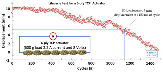
Figure 5.
Lifecycle test for a 6-ply TCP muscle at 600 g load 2.2 A current, 0.02 Hz and 8 Volts.
2.3. Comparison of TCP Actuators Properties with Shape Memory Alloy (SMA) Actuators and Pneumatic Artificial Muscles (PAM)
TCP actuators offer a large actuation range, significant mechanical power, silent operation, and is relatively inexpensive compared to other types of artificial muscles. However, they have low efficiency. SMA actuators consist of nickel and titanium alloy and offer high stress and power density but have low efficiency and varying properties with temperature, making them relatively expensive. PAM actuators offer high strain and output stress but are bulky due to the compressor and have a reduced effective power to weight ratio of the final robot. In comparison, 6-ply TCP artificial muscles are not bulky and can perform effectively while providing flexibility in design, making them advantageous for robotic applications. Table 1 summarizes the properties of these actuators, which can be used in robotics with each having its own advantages and disadvantages.

Table 1.
Comparing properties of the different artificial muscles that can be used in a robotic arm [22,23,24,25].
Advantages of TCP:
- Low volume of muscles makes it advantageous in the limited space of the 3D printed forearms and fingers.
- Light weight actuators do not add overall weight on the structure and results in reduced forces acting on the joints (elbow, shoulders, etc.) The TCP is a polymer-based actuator with a very small coating of silver (~100 nm) on the nylon fiber (0.2 mm yarn precursor).
- More flexible in actions and object manipulation through five fingers actuation with different gestures with the ability to actuate each finger separately.
- Highly compatible with soft robotic (TPU, silicone) applications, capability to embed actuators in flexible skins and grasp complex objects [19].
- Easily replaceable and low cost (price of muscle of 95 mm length is $0.4 [16]) for fabricating 6-ply TCP artificial muscles and the muscles can be manufactured in house or in a lab quickly.
- Highly customizable manufacturing process requiring very few components.
- Powerful (~9 N force from a 6-ply TCP) with a diameter of 2.4 mm having 5% strain for a current of 2.2 A input current and 8 V (Power = 17.6 W) at 0.0167 Hz actuation frequency. With a diameter of 2.4 mm (Stress = 2 MPa), duty cycle = 33%, and frequency of 0.0167 Hz, the muscles sustained lifecycle of ~1500.
- Good for low frequency applications. For example, during prolonged contraction, such as a grasping operation when TCP muscles are used in a robotic hand, we will keep holding an object for a while and release it.
Disadvantages of TCP:
- The current TCP actuated hand has limitations in terms of bending angles, forces, and degrees of freedom, and is limited to picking medium to big and light objects.
- Slow actuation speeds may limit the application of TCP, and more work is needed to reduce actuation time.
- A control system needs to be developed with sensors to determine the amount of actuation or contact with the object and control the finger positions based on feedback received.
2.4. A Study on the Application of PID Control System for 6-Ply TCP Actuators
The Twisted and Coiled Polymer (TCP) muscles with silver coating operate on Joule heating-based actuation. A system model is required to understand the motion of the TCP and use the model to apply control such as Proportional-Integral-Derivative (PID). A grey box system identification method was used to estimate a linear time invariant (LTI) system model. Jafarzadeh et al. [27] used a similar approach to perform system identification for 1-ply TCP actuator, using voltage as input and force as output.
For a better understanding of the TCP muscle displacement, data based on applied voltage and the time needed to reach steady state was collected for system identification. Experimental data was processed to determine the steady-state response gain. However, there are more parameters that affect the TCP muscle’s performance, such as the effect of temperature, strain, thermal capacity, and amount of pre-tension. The study of these other parameters is beyond the scope of this study.
Based on the experimental data collected, using voltage as input and displacement as output, the transfer function for the system was identified. This is shown in Figure 6. Using MATLAB’s System Identification tool, two transfer functions were obtained, namely tf1 (second order), as shown in Equation (1), and tf2 (first order), as shown in Equation (2). The transfer function tf1 provided a slightly better fit than tf2, but it was only marginal. Therefore, it is recommended to use tf2 going forward as it is first order and provides a good fit of 91%.
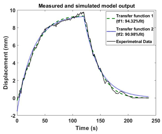
Figure 6.
System identification transfer functions fitness to data based on Steady state response gain for input of 7 V.
As compared to open loop, a common way to shorten the rising time of heating is based on the application of PID and other control methods to the input current [28,29]. To obtain the PID parameters, a Simulink model in MATLAB, shown in Figure 7, with the transfer function tf2, was developed to identify and tune the PID parameters with the PID tuner app in MATLAB, as shown in Equation (3). In the controller design section, the maximum input voltage was limited to 12 V to avoid overheating of TCP actuators. Using a higher voltage may degenerate the TCP actuators, causing them to fail due to overloading.
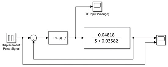
Figure 7.
Simulink model and the simulation of the model with PID parameters tuning.
The experimental setup, shown in Figure 8, involved using a laser distance sensor to track the displacement achieved by the actuator, a 6-ply TCP muscle hanging with a 1 kg weight to apply pre-tension to the actuator, a power supply supplying 12 V to the actuator, an Arduino board that runs the PID program, and the Arduino connected to a PC.
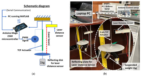
Figure 8.
(a) Schematic setup for conducting experiments with PID control. (b) Experimental setup for conducting experiments with PID control.
The PID control was implemented in MATLAB and sends a signal to the Arduino microcontroller board via a USB for serial communication. The USB connection allows the Arduino to send data and receive commands for Pulse Width Modulation (PWM)-based actuation of TCP with the help of metal-oxide-semiconductor field-effect transistor (MOSFET). The PWM controlled the voltage supplied to the actuator and controlled the actuation to reach the target distance. From Figure 9, we see that the experimental result followed the same voltage to displacement profile, as obtained during the simulation for different target displacements. The PID control was implemented on the 6-ply TCP actuator to shorten the rising time, fasten the output response, and reduce steady-state errors.
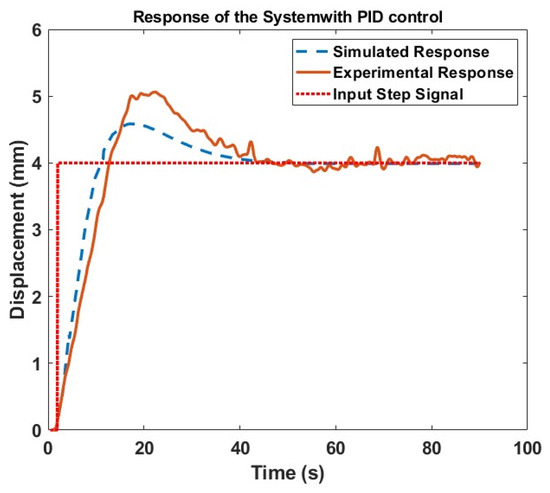
Figure 9.
PID response simulation of the system vs. experimental results of PID control for 6-ply TCP actuator.
The experimental results of the study showed that the implementation of the PID control system significantly improved the actuation response of the 6-ply TCP actuator. This is demonstrated by comparing the performance of the PID-based control with the open-loop control for achieving the same target displacement.
The experimental results in Figure 10 show that when the open loop control was used to achieve the same target displacement, it took approximately 60 s to reach the desired displacement. On the other hand, the PID-based control was able to achieve the target displacement in less than 10 s. This means that the PID control system was able to significantly shorten the rising time by approximately 80% and reduce steady-state errors of the TCP actuator.
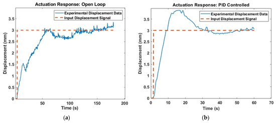
Figure 10.
Actuation response for speed to reach target displacement (a) Open loop vs. (b) PID controlled response.
Another experiment was conducted to investigate the effectiveness of PID control for TCP actuators with various displacement signal inputs. The purpose of this study was to determine how well the PID control could be implemented in TCP to produce different responses. The results of this study, presented in Figure 11, show that the PID control method was able to effectively match the different input signals. In other words, the PID control was able to adjust the TCP actuator response to accurately correspond to the varying input signals, indicating that it is a viable control strategy for TCP actuators.
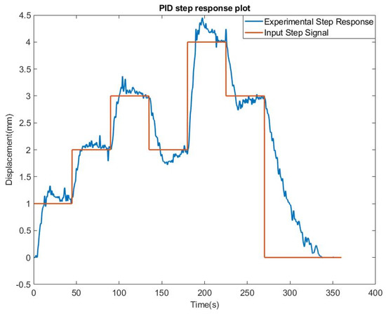
Figure 11.
Actuation response for different displacement input signals.
These results suggest that the use of PID control in TCP actuators provides a promising approach for improving their actuation and displacement capabilities. Furthermore, the results indicate that system identification and control design methods can help optimize the performance of TCP muscles in practical applications.
It should be noted that the PID-based control method is sensitive to parameters and difficult to transfer between different TCPs [28,29], but the process is simple to deploy. A major challenge in future applications of TCP actuators is to speed up their low response rate resulting from the slow cooling speed. TCP actuators are suitable for tasks which do not require a high-response frequency. Employing active cooling methods, such as fan cooling and liquid cooling or Peltier cooling, is a good choice to improve the response speed [30,31,32]. Future works should concentrate on improving the cooling speed. Determining the maximum allowable voltage without damage or failure to TCP may further improve actuation response through control.
The use of PID control in TCP actuators provides a promising approach for improving their actuation and displacement capabilities. System identification and control design methods can help optimize the performance of TCP muscles in practical applications.
3. Testing the 6-Ply TCP Actuators in the Robot
3.1. Development of Compliant TPU 3D Printed Fingers for Safer and Softer Human Interaction
The robotic hand is designed with CAD software and its approximate dimensions, shown in Figure 12, are similar to an adult human hand. Two different materials are used for the fabrication of the robotic hand. The fingers are developed by using flexible TPU (Thermoplastic Polyurethane) material, which eliminates the need to print multiple parts and assemble them to make the fingers. The remaining part of the hand is 3D printed with ABS (Acrylonitrile Butadiene Styrene) plastic material to take advantage of its rigid characteristics. Actuation occurs when the muscle heats up with a supplied voltage. However, it requires time to cool before the next actuation can take place. If the muscle is placed in a closed system, the cooling rate will be slow. The hand is designed with a greater number of holes and free spaces to allow for a faster cooling cycle. While implementing the TCP muscles, the fingers are pre-tensioned so that the TCP remains stiff and immediately responds when power is applied to it. As shown in Figure 12c, TCP muscles are installed close to each other in a tight space, providing actuation for each finger and reducing dependence on the more expensive servo motors. It was found that the maximum actuation angle obtained was 27 degrees for 12 V at a short heating time of 8 s, and 20 degrees at 8.5 V with 20 s heating time.
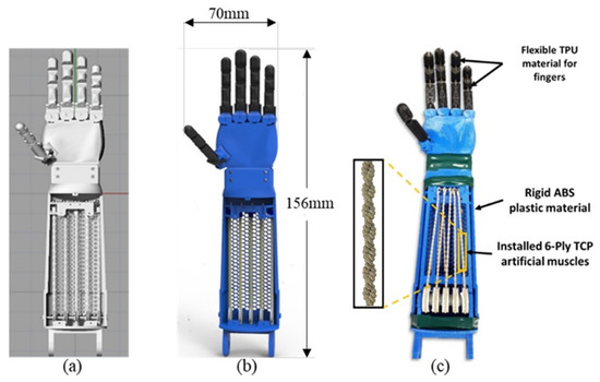
Figure 12.
(a) 3D CAD model (b) Rendered hand model (c) Picture of the 3D printed hand, equipped with 6-ply TCP muscles.
3.2. Description of HBS-1.2 Being Developed at HBS Lab, University of Texas at Dallas
The upper body of the HBS-1.2 consists of Dynamixel servos, SMA actuators, and 3D-printed ABS parts, with a total materials cost of around $10,000–$15,000 [11]. Other actuators, such as 2-ply and 3-ply TCPs, have also been utilized in previous studies [33], while sensing aspects of the HBS robot was discussed in a paper by Jafarzadeh et al. in 2020 [34]. The HBS robot is composed of mechatronic systems with Dynamixel and RC servo motors, and its controller consists of a desktop computer (Intel Core i7) and a microcontroller board (Nucleo STM32F767zi), which communicate through the Universal Asynchronous Receiver Transmitter (UART) [11]. The robot also comprises of additional 3D-vision systems like Sterolabs ZED Camera, and Unibrain Fire-I camera, as shown in Figure 13, However, they are not utilized in this study.
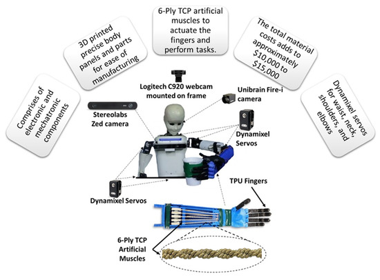
Figure 13.
Components of lightweight socially assistive robot HBS-1.2.
The robot is in an early stage of development and in this study is used for analyzing the implementation of soft artificial polymer-based actuators in the robotic hand. The HBS-1.2 can be developed for a wide range of applications, which include:
- Humanoid research and development: HBS-1.2 can be used in research for the development of actuators and sensors as there are limited humanoids actuated by muscle-like actuators.
- Education: HBS-1.2 can be used as a teaching tool in a robotics course because its modular design allows implementation of various sensors [10]. Additionally, its degrees of freedom (DOF) simplify robotic control (excluding the hand control).
- Medical: HBS-1.2 can be customized to fit the needs of rehabilitating children with autism [35].
- Unsafe conditions: HBS-1.2 can also be used as a tool and can potentially be used in situations that are too dangerous for humans.
3.3. Testing 6-Ply TCP Actuators in Robotic Hands with Vision-Assisted Pick and Place Experiment
To demonstrate a practical application of the 6-ply TCP muscles in a humanoid robot, an experiment was conducted where the HBS robot was used to pick and place an object, with the location of the object being detected using an RGB-based color detection technique. MATLAB was used to program the HBS-1.2 robot and control its motors using a USB2Dynamixel adapter and Pololu mini maestro servo controller [34]. The experiment involved the HBS robot detecting the location of a green cup with a diameter of 70 mm using an image processing technique, with the object’s location being extracted using MATLAB-based image processing techniques. Figure 14 demonstrates the experimental setup with an overhead camera view of the object detection.
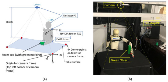
Figure 14.
Vision assisted pick and place experiment: (a) The schematic diagram of the robot and the coordinate system. (b) Picture showing the current setup of the HBS-1.2 robot.
To conduct the experiment, it is important to comprehend the coordinate systems and the procedural steps. The orientation of the axes in the robot frame and camera frame perspectives are detailed in Table 2, and the coordinate system and axis system of the robot frame and camera are illustrated in Figure 14a, which provides a schematic diagram of the setup. Additionally, Figure 14b provides a photograph of the HBS-1.2 robot in the HBS lab setup. The webcam is positioned 850 mm away from the table, which is 800 mm in height from the floor.

Table 2.
Axis orientation for Camera frame and Robot frame.
At the start of the experiment, the HBS robot uses an image processing technique to locate a green cup with a diameter of 70 mm. The location is then used to determine the joint angles required by the robot’s arm to reach the object through the use of inverse kinematics equations. Once the cup is located, the robot grasps it and transfers it to a predetermined location before returning to its original position. To run this experiment, the user must input the coordinates of the four corners of the table surface for both the camera frame (in pixels) and the robot frame (in cm). These coordinates are marked by the red color in Figure 14a. The MATLAB code is used to map the coordinates from the camera frame to the robot frame using a transformation matrix. The code is written in MATLAB and incorporates the axis orientation, as explained earlier, to illustrate the axis system.
3.3.1. Transformation of Coordinates to Robotic Coordinate System
Calibration techniques rely on sets of points whose relative coordinates in global coordinate frame are known, and whose corresponding coordinates in camera frame are also known. P. Corke [36] explains the homogeneous transformation approach, in Section 11.2.1 of the book, that allows the direct estimation of a camera matrix. The elements of the matrix comprise of the camera’s intrinsic and extrinsic parameters. Here, the intrinsic parameters describe the focal length, image center, distortion, and skew, while the extrinsic parameters relate to the camera’s position and orientation in the global frame of reference. Calibration requires a target with N number of points, with known coordinates, in both the target frame and the image frame. By utilizing these points, a matrix equation is formed, which is then solved by using least squares to determine the unknown elements of the camera matrix. Tymchyshyn et al. in [37] also explain the affine transformation of 2D points. Using a similar approach, as explained in [36,37,38], a transformations matrix is calculated for HBS-1.2. A transformation of 2D points can be expressed as Equation (4):
where, is the matrix of the camera coordinates, is the matrix of the robot coordinates, and is the transformation matrix. Four corner points (red circular points, labeled), shown in Figure 14, are recorded in the camera coordinate frame (pixels) as well as the robot coordinate frame (cm). By capturing the set of four points in the camera coordinate frame (pixels), as well as the robot coordinate frame (cm), a matrix Equation (5) is formed to determine the unknown elements of the matrix as follows:
where, the matrix comprises of six vectors of unknowns, , , , and represent the top left, top right, bottom left, and bottom right corner points, respectively, of the camera frame. Similarly, , , , and represent the top left, top right, bottom left, and bottom right corner points, respectively, of the robot frame. The Y coordinate was assumed to be constant as we considered planar pick and place in the X–Z plane.
The above form is useful when the correspondence between the points is known, and parameters of the transformation matrix need to be determined. In this case, the camera frame coordinates are in pixels and the corresponding robot frame coordinates are in cm. The equation is then solved by least squares using MATLAB [36]. In MATLAB, the transformation matrix is calculated by using the syntax , which returns a least-squares solution to the system of equations. Multiplying this transformation matrix to any set of coordinates from the camera’s frame converts it to the coordinates in the robot’s frame of reference. The converted points are then used in inverse kinematic equations to determine the joint angles of the robotic arm and reach the location of the target object. We may also add a safety radius if desired for some experiments, like reaching an object without touching.
3.3.2. Inverse Kinematics to Determine Joint Angles
Based on the robot frame coordinate, joint angles are calculated for the robotic arm to reach the target position. To calculate the joint angle, inverse kinematic equations are used. As seen in Figure 15, we first solve Equation (6) to obtain the value of the joint angles q2 and then use the value for q2 to solve Equation (7) to find the joint angle q1.
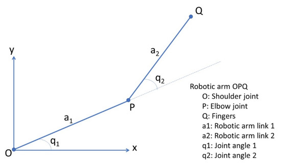
Figure 15.
Schematic diagram of the robotic arm showing the joint angles and links.
These calculated joint angles (q1 and q2), guide the robotic arm to reach the target location (x, y) or an object to perform tasks, like grasping, when instructed. These principles are implemented in a MATLAB code and demonstrated with HBS-1.2 robot by performing a pick and place experiment.
3.3.3. Vision Assisted Pick and Place Experiment and Light Condition
In the experiment, the performance of the HBS-1.2 robot was found to be better under diffused lighting conditions. To determine the optimal light conditions for the robot to process images and locate objects using the Logitech C922 webcam pro, a study of light conditions was conducted as illustrated in Figure 16a. It was observed that light conditions can have a detrimental effect on the robot’s ability to accurately locate an object, resulting in reduced pixel capture of the object, as shown in Figure 16b. The study also tested the minimum size of square green colored blocks that can be recognized and used in image processing, with the largest block measuring 40 mm × 40 mm and the smallest measuring 5 mm × 5 mm. Four blocks with different sizes were used, as shown in Figure 16c, and the smallest block was processed by the robot under ideal light conditions using the Logitech C922 camera. However, the robot’s ability to accurately locate an object remained inconsistent even under those conditions.
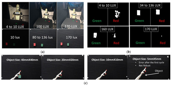
Figure 16.
(a) Light intensity measured using an iOS app designed for measuring light intensities. Any standard light meter can also be used for this purpose (b) Number of pixels captured under different light conditions with Logitech C922 webcam (c) The smallest object size being detected by the vision system.
The variation in calculated distance between two objects (red and green) as shown in Figure 16a, for different light intensities was investigated and normal distribution curves with a 95% confidence interval were plotted, as depicted in Figure 17. The results indicated that light intensities ranging from 34 lumens/m2 to 108 lumens/m2 provided a very small variation in calculated distance at 95% confidence intervals, which was close to the actual value. As the light intensity increased, accuracy decreased, and the variation in calculated distance became worse, particularly for a light intensity of 160 lumens/m2. If the robot’s vision system does not receive precise coordinates from the objects, the calculations made to obtain the robot joint angles will contain errors, and the robot will fail to grip the object. In the pick and place experiment using the 6-ply TCP actuated hand, the location of the cup was obtained by taking a picture using the camera mounted on the frame, and utilizing the RGB-based color detection technique. This allowed for the location of the object to be determined and transformed into the robot’s frame of reference. Once the location was determined, the inverse kinematics equations were utilized to calculate the joint angles of the robotic arm. Based on these calculations, the robot was able to successfully reach and pick up the cup using the PWM technique to actuate the TCP muscles, as illustrated in Figure 18. After picking up the cup, it was placed at a predetermined location, and the robot returned to its original position.
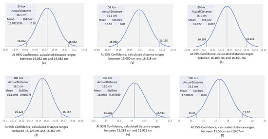
Figure 17.
Normal Distribution Curves for Calculated Distance (cm) between objects for different light intensities at (a) 34 lumens/m2 (b) 53 lumens/m2 (c) 80 lumens/m2 (d) 108 lumens/m2 (e) 136 lumens/m2 and (f) 160 lumens/m2, showing that at higher light intensities, there is larger variation in the calculated distances (cm) between objects due to loss in quality of capturing pixels.

Figure 18.
HBS robot performing the full sequence of picking and placing the object.
The role of the thumb was found to be significant in the ease of grasping the cup, as noted in previous work by Jones et al. [39]. Furthermore, video demonstrations of the functioning of the robot for this experiment are provided in the Supplementary File. Overall, the experiment demonstrates that TCP muscles are effective in robotic hands and fingers and have potential for various applications.
4. Discussion on Critical Factors in the Development of Socially Assistive Robots
A Short Survey on Desired Features of SAR and Its Acceptability by the Users
Prior to advancing the development of the SAR, a survey was conducted at the University of Texas at Dallas to gather insights on the desired features and appearance of a SAR from the perspective of potential users. Figure 19 presents the survey results on the types of features and appearance preferred for the SAR. The survey results revealed the desired individual features such as speech control, physical task performance, and security. Additionally, support for cognitive functions of patients through activities that promote brain simulation is deemed one of the most critical features for the SAR. It is worth highlighting that the appearance of the SAR can significantly affect its acceptability among patients. As such, a child-sized SAR with a friendly appearance would increase the acceptability of the HBS-1.2 SAR.
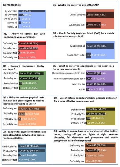
Figure 19.
Survey conducted from students at University of Texas at Dallas, on the design features of HBS-1.2 robot for assisting patients suffering from Alzheimer’s Disease.
While we acknowledge the limitation of the current survey due to the limited age range of participants, we would like to emphasize the valuable insights gained from the responses obtained. Future research will address this limitation and include a wider range of participants to enhance the robustness of our findings. It is important to recognize that our socially assistive robot is designed not only to directly assist Alzheimer’s disease patients but also to provide support to the caregivers and family members who play a significant role in their care. Their active involvement in customizing and tailoring the SAR’s features, such as touch screen input, can contribute to a more effective and personalized care experience for the patients. The opinions and preferences of younger individuals provide meaningful perspectives, particularly in relation to the inclusion of touch screen input as an option on SAR. Additionally, our survey results shed light on the importance of customization and personalization features in SARs, which can significantly impact the well-being and comfort of Alzheimer’s disease patients. We acknowledge the need for more extensive surveys involving a broader age range in future studies to further validate and generalize our findings. The incorporation of responses from older individuals, caregivers, and those with direct experience with Alzheimer’s disease patients will be a crucial step in obtaining a more comprehensive understanding of the requirements and preferences for SAR development.
Humanoid robots such as NAO [40], Bandit [41], and Human Support Robot [42] are some examples that fulfill a variety of personal needs like training and encouraging physical exercise among patients and serving as a companion. MARIO, a companion robot, has also been involved in research to better understand interactions between robots and patients with dementia and determine the challenges faced to guide the future design of SARs [43]. Another study [44] presented a systematic mapping study of application service robots in the assistance of human care and found that entertainment and therapy were the most common applications, and verbal communication was the most common mode of communication to help patients with cognitive impairments. Patients and caregivers expect SARs to support cognitive functions, provide emotional support, and alert them of emergencies. The desired features and capabilities of Socially Assistive Robots (SARs), as requested by patients and caregivers, have been identified through findings and surveys from Human–Robot Interaction (HRI). To aid in the designing of SAR, these desired features and capabilities are summarized in Figure 20.
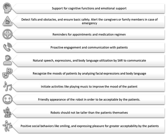
Figure 20.
Desired features of SARs, as requested by patients and caregivers, based on the findings and surveys from Human Robot Interaction (HRI).
The features include detecting obstacles to prevent falls and accidents, as well as ensuring basic safety of the house such as turning off the water, gas and lights, which can help in reducing the workload and providing peace of mind to the caregivers [45,46]. Reminding patients of appointments and medication regimen [47], proactively initiating communication by recognizing moods, and utilizing facial expressions and body language to communicate all enhance the user experience and make SARs more acceptable and likeable to patients [48]. Also, SARs should have a friendly appearance and must not be taller than the patients themselves [47]. A critical review of several different studies conducted by researchers [44] determined that the acceptability of robots by patients suffering from physical and cognitive disabilities can be improved if the robots can have personalized and human-like communication capabilities. Another study [49] explored the factors influencing the acceptability of the social robots and indicated that the perceived usefulness of the robot had significant impact on the acceptability. Positive social behaviors like smiling and expressing pleasure can also help achieve greater acceptability by the patients [46].
5. Mobility Consideration and Artificial Intelligence for SARs
5.1. Mobilizing HBS-1.2
Mobility is a major factor in modern humanoid robotics. The HBS-1 is a modular research robot that is designed to be built with 3D-printed parts and off the shelf components. Although the HBS-1 possesses an ample number of degrees of freedom (DOF), specifically, 51, and incorporates a bipedal structure, there has been limited emphasis placed on its walking capabilities [11]. HBS-1.2 is only the upper body part that is used for manipulation of an object while in a stationary frame [33]. The next step in the HBS-1 project is to integrate a suitable mobile robotic platform to mobilize the HBS-1.2 humanoid robot, similar to Buddy robot [10,11], which is developed in HBS lab at UT Dallas.
In order for the mobile robotic platform to be suitable for the HBS-1, it must meet specific design requirements without limiting the robot’s range of applications. The design criteria of the HBS-1 dictate that it must be anatomically proportional, child-sized, have sufficient degrees of freedom (DOFs). Thus, finding a mobile robotic platform that meets these requirements is crucial. The relative dimensions of the HBS-1 were obtained from Wu et al. [11]. The robot has a pelvis that is 60 mm tall, a height of 58 cm from the thigh to the floor, and a weight of approximately 5 kg (11 lbs). Based on these dimensions, the height of the platform should be 64 cm, with a width of approximately 19 cm and a payload capacity of at least 5 kg.
We have performed an exhaustive search for commercially available mobile bases for integration to robots like HSB 1.2. The mobile robotic platforms were sorted into two categories, commercial/industrial, as shown in Table 3, and open source, as shown in Table 4. Then, a list was compiled containing mobile platforms that were being sold, cost, features, and vendor. Prices range from low ($), medium ($$), high ($$$), and very high ($$$$). Pricing for open-source platforms is relative to only other open-source platforms. Pricing for industrial/commercial platforms is relative to only other industrial/commercial platforms. Additional robots searched in this study have been presented in Supplementary Materials, Appendix A in Table A1 and Table A2.

Table 3.
Industrial/commercial mobile robotic platform [50,51,52,53,54].

Table 4.
Open-source mobile robotic platform [55,56,57,58,59,60].
Upon conducting a thorough search for available mobile platforms that meet the requirements for HBS-1.2, it was discovered that industrial/commercial mobile robotic platforms have high payloads, powerful processors, and capable sensors, but are prohibitively expensive. Conversely, open-source software mobile robotic platforms are affordable but have low payloads, weak processors and sensors, and limited support. Furthermore, no existing open-source hardware and software mobile robotic platforms met the specifications required by the HBS-1. Consequently, an option that warrants further exploration is the design and development of a 3D-printed mobile robotic base, containing only 3D printed and off-the-shelf components. This will allow for greater customizability to adhere to the HBS-1’s exact dimensional and geometric requirements. This will also allow the platform to adhere to the design criteria of the HBS-1 of containing only 3D printed and off-the-shelf parts. Designing and developing a 3D-printed mobile robotic base will allow greater customizability to conform to the exact dimensional and geometric requirements that the HBS-1 needs.
The BUDDY social robot, intended for indoor applications and assistive care, serves as an example of a custom-built mobile platform tailored specifically for assistive robots. It is built with 3D-printed parts and off-the-shelf components. The robot has successfully demonstrated its ability to pick up and place objects in a lab setting. Its mobile platform is anatomically proportional, has sufficient degrees of freedom, and is composed entirely of 3D-printed and off-the-shelf components. The robot has uniquely designed soft grippers that enable it to travel around indoor spaces to perform pick and place tasks with objects.
The BUDDY social robot successfully completed different pick and place tests, including both short-distance (6 ft) and long-distance (25 ft 8 in) pick and place trials, demonstrating its capability to successfully complete these tasks. Furthermore, the BUDDY social robot has demonstrated its ability to perform a hard-coded, closed-loop routine around the lab after picking an object and placing it back after completing the lap, as illustrated in Figure 21. The robot traversed through tight hallways with cords and bumps, retrieving and delivering objects along an 87 ft × 6 in trajectory, which featured four distinct straight sections measuring 24 ft—20 in, 16 ft—70 in, 24 ft—96 in, and 8 ft. Overall, the BUDDY social robot showcases the potential of 3D-printed and off-the-shelf components to create capable robots for indoor applications.
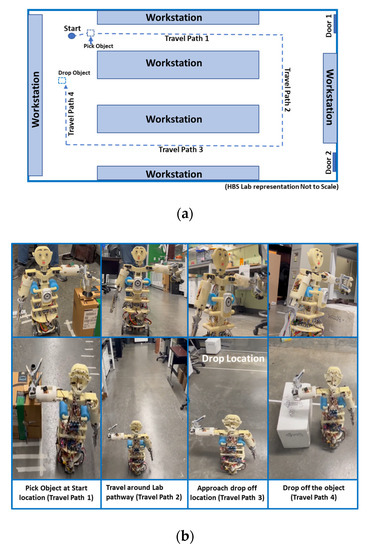
Figure 21.
(a) Layout of the HBS lab where BUDDY social robot was tested for one lap around the lab pathway (b) BUDDY Robot performing the pick and place task in the lab pathway.
The mobile platform options presented in the study reveal that the available commercial mobile platforms either fail to meet the comprehensive requirements of the HBS robot or come at prohibitively high costs. Drawing from the case of the BUDDY social robot, it becomes evident that a custom-built mobile platform, specifically tailored to suit the needs of the HBS robot, is essential. By adopting a design approach that incorporates 3D printing and utilizes off-the-shelf components, the development of such a custom mobile platform becomes feasible, effectively mitigating expenses and ensuring a cost-effective solution for the HBS robot.
5.2. Incorporation of Artificial Intelligence and IoT Devices
Artificial intelligence (AI) is a wide branch of computer science that deals with giving computers decision making or problem-solving capabilities. Currently, robots such as Boston Dynamics Spot uses AI technologies to traverse difficult terrain and prevent collisions in its path [61]. Social robots, such as Sophia, developed by Hanson Robotics, utilizes natural language processing, a subset of ML, to communicate with users [62]. Robots like Sophia can be used in nursing homes as a companion to elderly people. We have predicated the emergence of humanoid robots in solving societal problems more than a decade ago and we are seeing this effect in the last few years [63,64], particularly during the global pandemic.
ML technologies, such as computer vision and natural language processing, can be implemented on the HBS-1.2 robot to increase its capabilities and versatility. Applying natural language processing algorithms to the HBS-1.2 will provide the robot with the ability to listen and understand the user’s speech. Recently, our group, Jafarzadeh et al. [65], demonstrated the use of natural language processing (NLP) in end-to-end control of the robotic arm by running deep neural networks to process speech. Additionally, computer vision can be used to enable the HBS-1.2 to pay attention to the user, providing the robot with more human-like traits. The multiple types of cameras on the HBS-1.2 robot, as mentioned previously, when fully integrated with the help of advanced machine learning techniques and computer vision algorithms, can enable it to recognize obstacles in its path and the location of objects for pick and place maneuvers.
Keeping track of medications, giving reminders, as well as supporting emotionally through playing music, or engaging in games, and practicing meditation are some examples of how patients can remain engaged and active [66]. These kinds of activities can also remove the effects of loneliness, as it will be possible to communicate with the robot or connect to family members and friends with the help of IoT devices. Jafarzadeh et al. developed a versatile and affordable sensor vest to be used in social humanoid robots. The vest is equipped with touch, temperature, gesture, distance, vision sensors, and a wireless communication module [34]. The following are the key components: (1) Adafruit MPR121 capacitive touch sensor, (2) IoT communication module Gesture sensing, (3) VL53L0X Range sensor, (4) SRF02 sonar proximity sensor- Ultrasound range sensing, (5) MCP9808 sensor-Temperature. Adding these features to the HBS-1.2 robot will further enhance its capabilities and make it possible to perform actions like controlling light switches, gas stoves, and capability to connect to emergency services to increase the safety of the patients.
Incorporating AI and IoT devices can significantly increase the capabilities and versatility of the HBS-1.2 robot. With AI technologies, natural language processing and computer vision algorithms can be implemented to provide the robot with the ability to listen and understand speech, recognize obstacles in its path, and have more human-like traits. Adding IoT devices like a sensor vest can further enhance its capabilities, such as controlling household appliances, tracking medications, and connecting to emergency services, making it an excellent companion for elderly people in nursing homes. This study provides valuable insights into the potential use of AI and IoT technologies in social humanoid robots like the HBS-1.2, which could have significant impacts on solving societal problems.
6. Summary and Conclusions
In conclusion, the HBS-1.2 robot that utilizes 6-ply TCP artificial muscles is a promising solution to address the physical, emotional, and cognitive needs of patients with dementia. Moreover, the robot’s design is versatile and can be customized for other purposes like military or airport medical scanning. Using 6-ply TCP artificial muscles in the robot’s fingers and hands offers significant advantages over conventional actuators, such as servo motors, including reduced weight, cost, and design complexity.
This paper provides a detailed explanation of the fabrication, annealing, and training process for the 6-ply TCP artificial muscles, along with experimental results demonstrating their performance. The PID control method has shown a significant improvement in the actuation response of the 6-ply TCP actuator, reducing the time to reach a target displacement from 60 s to less than 10 s. It is noteworthy that a 95 mm long 6-ply TCP actuator costs approximately $0.4.
In the pick and place experiment conducted on a 70 mm diameter cup, the 6-ply TCP muscles were successfully implemented in the fingers of the HBS-1.2 humanoid robot for the first time, demonstrating their effectiveness in actuation. Although the experiment did not employ PID control, it serves as a precursor to future endeavors aimed at refining the robot’s hand and augmenting the performance of the 6-ply TCP actuators in a robotic hand. An ideal range of light intensity of between 34 lumens/m2 and 108 lumens/m2 provides marginal variation in calculated distance at 95% confidence intervals, and minimum object size is identified for the best performance of the robot in vision-assisted pick and place experiments. The 6-ply TCP muscles are affordable, offer high-force output, and can operate silently for 1000 cycles at full capacity, making them a reliable and cost-effective option.
To enhance the HBS-1.2 robot’s versatility, future developments will include the integration of a mobile platform to provide comprehensive solutions for patients. The survey results reveal important features that need to be included, such as speech control, physical task performance, and security in a SAR. Additionally, the implementation of IoT and artificial intelligence can help fulfill the needs of Alzheimer’s disease patients and further enhance the robot’s capabilities and effectiveness. Deployment of the robot in a medical or nursing home setting will be conducted to evaluate its effectiveness and identify areas for improvement in future iterations. Overall, the HBS-1.2 robot that utilizes 6-ply TCP artificial muscles has the potential to revolutionize the way we care for patients with dementia and other conditions, significantly improving their quality of life.
Supplementary Materials
The following supporting information can be downloaded at: https://www.mdpi.com/article/10.3390/act12080312/s1, HBS-1.2: HBS Robot Actuated by 6-ply TCP as Lightweight Socially Assistive Robot. The movie is also available on our official YouTube Channel. https://youtu.be/fO5xgZ2Z1hM, (accessed on 26 July 2023).
Author Contributions
Conceptualization, A.P.S. and Y.T.; methodology, A.P.S., D.P., O.A. and P.S.M.; software, A.P.S., D.P. and T.L.; validation, A.P.S., D.P., O.A., P.S.M. and Y.T.; formal analysis, A.P.S., D.P., O.A., P.S.M. and Y.T.; investigation, A.P.S., D.P., O.A. and P.S.M.; resources, Y.T.; data curation, A.P.S., D.P., O.A. and P.S.M.; writing—original draft preparation, A.P.S., D.P., O.A., P.S.M., T.L., T.N. and Y.T.; writing—review and editing, A.P.S., D.P., O.A., P.S.M., T.L., T.N. and Y.T.; visualization, A.P.S., D.P., O.A. and P.S.M.; supervision, Y.T.; project administration, Y.T.; funding acquisition, Y.T. All authors have read and agreed to the published version of the manuscript.
Funding
This research received no external funding. It was supported by internal funding from Yonas Tadesse’s Research Enhancement Fund.
Data Availability Statement
Data is available upon request.
Conflicts of Interest
The authors declare no conflict of interest.
Appendix A

Table A1.
More mobile option from Industrial/commercial mobile robotic platform.
Table A1.
More mobile option from Industrial/commercial mobile robotic platform.
| Company | Fetch Robotics | Clearpath Robotics | Waypoint Robotics |
|---|---|---|---|
| Robot Name | Freight100 | Boxer | Vector 3D |
| Weight | 68 kg | 127 kg | N/A |
| Base Height | 14 in | 12 in | 20 in |
| Base Dimensions | 22 in diameter | 29.5 × 21.6 in | 30 × 20 in |
| Payload | 100 kg | 100 kg | 136 kg |
| Top Speed (mph) | 4.47 | 4.47 | 2.68 |
| Battery | 12 V SLA | Lithium Ion 24 V | 1 kWh LiFePO4 |
| Battery Life | 9 h | 12 h | 8+ h |
| Charge Time | 3 h | 4 h | N/A |
| Usage Environment | Indoors | Indoors | Industrial |
| Sensors | 2D laser 25 m 220°, 3D depth 2x Realsense D435 | Lidar 10 m, Stereo camera, rear sonar, odometery | 3D liDAR 360° FOV 90 m RANGE, camera |
| Computing: | i3 Haswell, 8 GB RAM, 120 GB SSD, Wifi, Bluetooth | N/A | N/A |
| Software | Ubuntu Linux LTS, ROS | Web-based, ROS Kinetic | Proprietary |
| Applications | ROS Navigation, Joystick Teleop, calibration | Gazebo, Light Control, Rviz, URDF Support | Remote Teleop |
| Price (USD) | $$$$ | $$$$ | $$$$$ |

Table A2.
More mobile option from Open-source mobile robotic platform.
Table A2.
More mobile option from Open-source mobile robotic platform.
| Company | Turtlebot | Ubiquity Robotics | Turtlebot | NASA JPL |
|---|---|---|---|---|
| Robot Name | Waffle | Magni- Silver | Turtlebot 2 | Open-Source-Rover |
| Weight | 1.8 kg | 13 kg | 6.3 kg | 12.7 kg |
| Base Height | 5.5 in | 10.43 in | 16.5 in | 12.0 in |
| Base Dimensions | 11.06 × 12.05 in | 17.29 × 16.43 in | 14 × 14 in | 24 × 14 in |
| Payload | 30 kg | 100 kg | 2 kg | N/A |
| Top Speed (mph) | 0.58 | 2.2 | 1.56 | 3.91 |
| Battery | LiPo 11.1 V 1800 mAh | N/A | LiPo 4400 mAh | 5200 mAh |
| Battery Life | 2 h | N/A | 4–6 h | 5 h |
| Charge Time | 2.5 h | N/A | 2–3 h | ~1.7 h |
| Usage Environment | Indoors | Indoors | Indoors | Indoors and Outdoors |
| Sensors | 3 axis gyro, accelerometer, magnetometer, 360° LiDAR, camera | Camera, Hall sensor, sonar | Intel RealSense 3D camera, ORBBEC camera, accelerometer, gyro, compass, bumper sensor, edge detection | N/A |
| Computing: | Raspberry Pi 3 | Raspberry Pi 4 | Intel NUC, 8 GB RAM, 120 GB SSD, WIFI | Raspberry Pi 3 |
| Software | DYNAMIXEL SDK | Ubuntu, ROS Kinetic, Core Magni Packages | DYNAMIXEL SDK | N/A |
| Applications | ROS | ROS | ROS | N/A |
| Link | www.robotis.us/turtlebot-3-waffle-pi/, (accessed on 27 July 2023) | store.ubiquityrobotics.com/, (accessed on 27 July 2023) | www.trossenrobotics.com/, (accessed on 27 July 2023) | github.com/nasa-jpl/open-source-rover, (accessed on 27 July 2023) |
| Price (USD) | $$ | $$ | $$$ | $$$ |
References
- Alzheimer’s Association. 2021 Alzheimer’s disease facts and figures. Alzheimer’s Dement. 2021, 17, 327–406. [Google Scholar] [CrossRef]
- Centers for Disease Control and Prevention. U.S. Burden of Alzheimer’s Disease, Related Dementias to Double by 2060. Centers for Disease Control and Prevention. Available online: https://www.cdc.gov/media/releases/2018/p0920-alzheimers-burden-double-2060.html (accessed on 20 June 2021).
- Campbell, S. New Research: 7.8 Million Direct Care Jobs Will Need to Be Filled by 2026. Available online: https://phinational.org/ (accessed on 20 June 2021).
- Friedman, E.M.; Shih, R.A.; Langa, K.M.; Hurd, M.D.; Boustani, M.; Alder, C.A.; Solid, C.A.; Reuben, D. US prevalence and predictors of informal caregiving for dementia. Health Aff. 2015, 34, 1637–1641. [Google Scholar] [CrossRef]
- Vitanza, A.; D’Onofrio, G.; Ricciardi, F.; Sancarlo, D.; Greco, A.; Giuliani, F. Assistive Robots for the Elderly: Innovative Tools to Gather Health Relevant Data. In Data Science for Healthcare; Springer: Berlin/Heidelberg, Germany, 2019; pp. 195–215. [Google Scholar]
- Pandey, A.K.; Gelin, R. A Mass-Produced Sociable Humanoid Robot: Pepper: The First Machine of Its Kind. IEEE Robot. Autom. Mag. 2018, 25, 40–48. [Google Scholar] [CrossRef]
- McGinn, C.; Bourke, E.; Murtagh, A.; Donovan, D.; Patrick, L.; Cullinan, M.F.; Kelly, K. Meet Stevie: A Socially Assistive Robot Developed Through Application of a ‘Design-Thinking’ Approach. J. Intell. Robot. Syst. 2020, 98, 39–58. [Google Scholar] [CrossRef]
- Kittmann, R.; Fröhlich, T.; Schäfer, J.; Reiser, U.; Weißhardt, F.; Haug, A. Let me introduce myself: I am Care-O-bot 4, a gentleman robot. In Proceedings of the Mensch und Computer 2015, Stuttgart, Germany, 6–9 September 2015. [Google Scholar]
- Park, D.; Hoshi, Y.; Mahajan, H.P.; Kim, H.K.; Erickson, Z.; Rogers, W.A.; Kemp, C.C. Active robot-assisted feeding with a general-purpose mobile manipulator: Design, evaluation, and lessons learned. Robot. Auton. Syst. 2020, 124, 103344. [Google Scholar] [CrossRef]
- Potnuru, A.; Jafarzadeh, M.; Tadesse, Y. 3D printed dancing humanoid robot “Buddy” for homecare. In Proceedings of the 2016 IEEE International Conference on Automation Science and Engineering (CASE), Fort Worth, TX, USA, 21–25 August 2016; IEEE: Manhattan, NY, USA, 2016; pp. 733–738. [Google Scholar]
- Wu, L.; Larkin, M.; Potnuru, A.; Tadesse, Y. HBS-1: A modular child-size 3D printed humanoid. Robotics 2016, 5, 1. [Google Scholar] [CrossRef]
- Bao, J.; Ho, C.; Xu, H.; Wu, Y.; Yan, B.; Lin, Y.; Chen, K.; Xu, J. Fast Actuating Multi-Helically Heated Twisted and Coiled Polymer Actuator. IEEE Robot. Autom. Lett. 2023, 8, 1547–1554. [Google Scholar] [CrossRef]
- Piao, C.; Jang, H.; Lim, T.; Kim, H.; Choi, H.R.; Hao, Y.; Suk, J.W. Enhanced dynamic performance of twisted and coiled soft actuators using graphene coating. Compos. Part B Eng. 2019, 178, 107499. [Google Scholar] [CrossRef]
- Wu, C.; Zhang, Z.; Zheng, W. A twisted and coiled polymer artificial muscles driven soft crawling robot based on enhanced antagonistic configuration. Machines 2022, 10, 142. [Google Scholar] [CrossRef]
- You, T.L.; Rossiter, J.; Philamore, H. Robotic Fish driven by Twisted and Coiled Polymer Actuators at High Frequencies. In Proceedings of the 2023 IEEE International Conference on Soft Robotics (RoboSoft), Singapore, 3–7 April 2023; IEEE: Manhattan, NY, USA, 2023; pp. 1–6. [Google Scholar]
- Hamidi, A.; Almubarak, Y.; Rupawat, Y.M.; Warren, J.; Tadesse, Y. Poly-Saora robotic jellyfish: Swimming underwater by twisted and coiled polymer actuators. Smart Mater. Struct. 2020, 29, 045039. [Google Scholar] [CrossRef]
- Matharu, P.S.; Ghadge, A.A.; Almubarak, Y.; Tadesse, Y. Jelly-Z: Twisted and coiled polymer muscle actuated jellyfish robot for environmental monitoring. Acta IMEKO 2022, 11, 1–7. [Google Scholar] [CrossRef]
- Matharu, P.S.; Gong, P.; Guntaka, K.P.R.; Almubarak, Y.; Jin, Y.; Tadesse, Y.T. Jelly-Z: Swimming performance and analysis of twisted and coiled polymer (TCP) actuated jellyfish soft robot. Sci. Rep. 2023, 13, 11086. [Google Scholar] [CrossRef] [PubMed]
- Almubarak, Y.; Tadesse, Y.; Maly, N.X. Fully embedded actuators in elastomeric skin for use in humanoid robots. In Proceedings of the SPIE: Electroactive Polymer Actuators and Devices (EAPAD) XX, Online, 27 April–8 May 2018; Volume 1059416, p. 1059416. [Google Scholar]
- Saharan, L.; Tadesse, Y. Novel twisted and coiled polymer artificial muscles for biomedical and robotics applications. In Materials for Biomedical Engineering; Elsevier: Amsterdam, The Netherlands, 2019; pp. 45–75. [Google Scholar]
- Saharan, L.; Tadesse, Y. Fabrication parameters and performance relationship of twisted and coiled polymer muscles. In Proceedings of the ASME International Mechanical Engineering Congress and Exposition, Columbus, OH, USA, 30 October–3 November 2016; Volume 50688, p. V014T11A028. [Google Scholar]
- Haines, C.S.; Lima, M.D.; Li, N.; Spinks, G.M.; Foroughi, J.; Madden, J.D.W.; Kim, S.H.; Fang, S.; de Andrade, M.J.; Göktepe, F.; et al. Artificial muscles from fishing line and sewing thread. Science 2014, 343, 868–872. [Google Scholar] [CrossRef] [PubMed]
- Tadesse, Y. Electroactive polymer and shape memory alloy actuators in biomimetics and humanoids. In Proceedings of the Electroactive Polymer Actuators and Devices (EAPAD) 2013, Denver, CO, USA, 4–7 March 2019; Volume 8687, p. 868709. [Google Scholar]
- Liang, W.; Liu, H.; Wang, K.; Qian, Z.; Ren, L.; Ren, L. Comparative study of robotic artificial actuators and biological muscle. Adv. Mech. Eng. 2020, 12, 1687814020933409. [Google Scholar] [CrossRef]
- Zhang, J.; Sheng, J.; O’Neill, C.T.; Walsh, C.J.; Wood, R.J.; Ryu, J.-H.; Desai, J.P.; Yip, M.C. Robotic artificial muscles: Current progress and future perspectives. IEEE Trans. Robot. 2019, 35, 761–781. [Google Scholar] [CrossRef]
- Matharu, P.S.; Wang, Z.; Costello, J.H.; Colin, S.P.; Baughman, R.H.; Tadesse, Y.T. SoJel—A 3D printed jellyfish-like robot using soft materials for underwater applications. Ocean Eng. 2023, 279, 114427. [Google Scholar] [CrossRef]
- Jafarzadeh, M.; Wu, L.; Tadesse, Y. System identification of force of a silver coated twisted and coiled polymer muscle. In Proceedings of the ASME International Mechanical Engineering Congress and Exposition, Tampa, FL, USA, 3–9 November 2017; Volume 58387, p. V04BT05A027. [Google Scholar]
- Yip, M.C.; Niemeyer, G. On the control and properties of supercoiled polymer artificial muscles. IEEE Trans. Robot. 2017, 33, 689–699. [Google Scholar] [CrossRef]
- Arakawa, T.; Takagi, K.; Tahara, K.; Asaka, K. Position control of fishing line artificial muscles (coiled polymer actuators) from nylon thread. In Electroactive Polymer Actuators and Devices (EAPAD) 2016; SPIE: Washington, DC, USA, 2016; Volume 9798, pp. 545–556. [Google Scholar]
- Song, H.; Hori, Y. Force control of twisted and coiled polymer actuators via active control of electrical heating and forced convective liquid cooling. Adv. Robot. 2018, 32, 736–749. [Google Scholar] [CrossRef]
- Takagi, K.; Arakawa, T.; Takeda, J.; Masuya, K.; Tahara, K.; Asaka, K. Position control of twisted and coiled polymer actuator using a controlled fan for cooling. In Electroactive Polymer Actuators and Devices (EAPAD) 2017; SPIE: Washington, DC, USA, 2017; Volume 10163, pp. 566–573. [Google Scholar]
- Singh, R.; Mohapatra, S.; Matharu, P.S.; Tadesse, Y. Twisted and coiled polymer muscle actuated soft 3D printed robotic hand with Peltier cooler for drug delivery in medical management. Acta IMEKO 2022, 11, 1–6. [Google Scholar] [CrossRef]
- Tadesse, Y.; Wu, L.; Karami, F.; Hamidi, A. Biorobotic systems design and development using TCP muscles. In Proceedings of the Electroactive Polymer Actuators and Devices (EAPAD) XX, Online, 27 April–8 May 2018; Volume 10594, p. 1059417. [Google Scholar]
- Jafarzadeh, M.; Brooks, S.; Yu, S.; Prabhakaran, B.; Tadesse, Y. A wearable sensor vest for social humanoid robots with GPGPU, IoT, and modular software architecture. Robot. Auton. Syst. 2020, 139, 103536. [Google Scholar] [CrossRef]
- Burns, A.; Tadesse, Y. The mechanical design of a humanoid robot with flexible skin sensor for use in psychiatric therapy. In Proceedings of the Electroactive Polymer Actuators and Devices (EAPAD) 2014; SPIE: Washington, DC, USA, 2014; Volume 9056, p. 90562H. [Google Scholar]
- Corke, P. Robotics, Vision and Control: Fundamental Algorithms in MATLAB® Second, Completely Revised; Springer: Berlin/Heidelberg, Germany, 2017. [Google Scholar]
- Tymchyshynm, V.B.; Andrii, K. Beginner’s guide to mapping simplexes affinely. ResearchGate 2019, 4. [Google Scholar] [CrossRef]
- Goshtasby, A.A.A. Advances in Computer Vision and Pattern Recognition; Springer: Berlin/Heidelberg, Germany, 2012; pp. 7–66. [Google Scholar]
- Shiota, K.; Kokubu, S.; Tarvainen, T.V.; Sekine, M.; Kita, K.; Huang, S.Y.; Yu, W. Enhanced Kapandji test evaluation of a soft robotic thumb rehabilitation device by developing a fiber-reinforced elastomer-actuator based 5-digit assist system. Robot. Auton. Syst. 2019, 111, 20–30. [Google Scholar] [CrossRef]
- Shamsuddin, S.; Ismail, L.I.; Yussof, H.; Zahari, N.I.; Bahari, S.; Hashim, H.; Jaffar, A. Humanoid robot NAO: Review of control and motion exploration. In Proceedings of the 2011 IEEE International Conference on Control System, Computing and Engineering, Penang, Malaysia, 25–27 November 2011. [Google Scholar] [CrossRef]
- Fasola, J.; Matarić, M.J. A Socially Assistive Robot Exercise Coach for the Elderly. J. Human-Robot Interact. 2013, 2, 3–32. [Google Scholar] [CrossRef]
- Yamamoto, T.; Terada, K.; Ochiai, A.; Saito, F.; Asahara, Y.; Murase, K. Development of Human Support Robot as the research platform of a domestic mobile manipulator. ROBOMECH J. 2019, 6, 4. [Google Scholar] [CrossRef]
- Kouroupetroglou, C.; Casey, D.; Raciti, M.; Barret, E.; D’Onofrio, F.; Giuliani, F.; Greco, A.; Sancarlo, D.; Mannion, A.; Whelan, S.A.; et al. Interacting With Dementia: The MARIO Approach. Stud. Health Technol. Inform. 2017, 242, 38–47. [Google Scholar] [PubMed]
- Whelan, S.; Murphy, K.; Barrett, E.; Krusche, C.; Santorelli, A.; Casey, D. Factors affecting the acceptability of social robots by older adults including people with dementia or cognitive impairment: A literature review. Int. J. Soc. Robot. 2018, 10, 643–668. [Google Scholar] [CrossRef]
- Pilotto, A.; D’Onofrio, G.; Benelli, E.; Zanesco, A.; Cabello, A.; Nargeli, M.C.; Wanche-Politis, S.; Seferis, K.; Sancarlo, D.; Kilias, D. Information and communication technology systems to improve quality of life and safety of Alzheimer’s disease patients: A multicenter international survey. J. Alzheimer’s Dis. 2011, 23, 131–141. [Google Scholar] [CrossRef]
- Pino, M.; Boulay, M.; Jouen, F.; Rigaud, A.-S. “Are we ready for robots that care for us?” Attitudes and opinions of older adults toward socially assistive robots. Front. Aging Neurosci. 2015, 7, 141. [Google Scholar] [CrossRef]
- Korchut, A.; Szklener, S.; Abdelnour, C.; Tantinya, N.; Hernández-Farigola, J.; Ribes, J.C.; Skrobas, U.; Grabowska-Aleksandrowicz, K.; Szczęśniak-Stańczyk, D.; Rejdak, K. challenges for service robots—Requirements of elderly adults with cognitive impairments. Front. Neurol. 2017, 8, 228. [Google Scholar] [CrossRef]
- Tapus, A.; Tapus, C.; Mataric, M.J. The use of socially assistive robots in the design of intelligent cognitive therapies for people with dementia. In Proceedings of the 2009 IEEE International Conference on Rehabilitation Robotics, Kyoto, Japan, 23–26 June 2009; pp. 924–929. [Google Scholar]
- Saari, U.A.; Tossavainen, A.; Kaipainen, K.; Mäkinen, S.J. Exploring factors influencing the acceptance of social robots among early adopters and mass market representatives. Robot. Auton. Syst. 2022, 151, 104033. [Google Scholar] [CrossRef]
- Wise, M.; Ferguson, M.; King, D.; Diehr, E.; Dymesich, D. Fetch and freight: Standard platforms for service robot applications. In Proceedings of the IJCAI’16 Workshop on Autonomous Mobile Service Robots, New York, NY, USA, 12 July 2016. [Google Scholar]
- Waypoint-Robotics. Vector™—Industrial Strength, OmniDirectional, Autonomous Mobile Robot. Waypoint Robotics. Available online: https://waypointrobotics.com/vector-robotic-mobility-platform/ (accessed on 20 June 2021).
- ClearpathRobotics. Robots. Clearpath Robotics. Available online: https://clearpathrobotics.com/jackal-small-unmanned-ground-vehicle/ (accessed on 27 July 2023).
- Mobile-Industrial-Robots. MiR100. Mobile Industrial Robots. Available online: https://www.mobile-industrial-robots.com/solutions/robots/mir100/ (accessed on 20 June 2021).
- Festo. Robotino 4: For Research and Education. Festo. Available online: https://ip.festo-didactic.com/InfoPortal/Robotino/Overview/EN/index.html (accessed on 20 June 2021).
- JPL-NASA. JPL’s Open Source Build-It-Yourself Rover. NASA. Available online: https://github.com/nasa-jpl/open-source-rover (accessed on 27 June 2023).
- Trossen-Robotics. Turtlebot 2i Mobile ROS Platform. Available online: https://www.turtlebot.com/turtlebot2 (accessed on 10 June 2021).
- Ubiquity-Robotics. Meet Magni. Available online: https://www.ubiquityrobotics.com/product/magni-silver/ (accessed on 27 July 2023).
- Robotis. Turtlebot 3 Waffle Pi. Available online: https://www.robotis.us/turtlebot-3-waffle-pi/ (accessed on 27 July 2023).
- Robotis. Turtlebot 3 Burger. Available online: https://www.robotis.us/turtlebot-3-burger-us/ (accessed on 27 July 2023).
- E.E.S. Agency. 3D Print Your Own MARS Rover with ExoMy. Available online: https://www.esa.int/Enabling_Support/Space_Engineering_Technology/3D_print_your_own_Mars_rover_with_ExoMy (accessed on 30 June 2021).
- Boston-Dynamics. Spot Transformative Mobility. Available online: https://www.bostondynamics.com/spot (accessed on 30 June 2021).
- Parviainen, J.; Coeckelbergh, M. The political choreography of the Sophia robot: Beyond robot rights and citizenship to political performances for the social robotics market. AI Soc. 2020, 36, 715–724. [Google Scholar] [CrossRef]
- Hanson, D.; Bergs, R.; Tadesse, Y.; White, V.; Priya, S. Enhancement of EAP actuated facial expressions by designed chamber geometry in elastomers. In Proceedings of the Smart Structures and Materials 2006: Electroactive Polymer Actuators and Devices (EAPAD), San Diego, CA, USA, 22 March 2006; Volume 6168, pp. 49–57. [Google Scholar]
- Tadesse, Y.; Priya, S.; Stephanou, H.; Popa, D.; Hanson, D. Piezoelectric actuation and sensing for facial robotics. Ferroelectrics 2006, 345, 13–25. [Google Scholar] [CrossRef]
- Jafarzadeh, M.; Tadesse, Y. Convolutional Neural Networks for Speech Controlled Prosthetic Hands. arXiv 2019, arXiv:1910.01918. [Google Scholar]
- Clabaugh, C.; Matarić, M. Escaping oz: Autonomy in socially assistive robotics. Annu. Rev. Control. Robot. Auton. Syst. 2019, 2, 33–61. [Google Scholar] [CrossRef]
Disclaimer/Publisher’s Note: The statements, opinions and data contained in all publications are solely those of the individual author(s) and contributor(s) and not of MDPI and/or the editor(s). MDPI and/or the editor(s) disclaim responsibility for any injury to people or property resulting from any ideas, methods, instructions or products referred to in the content. |
© 2023 by the authors. Licensee MDPI, Basel, Switzerland. This article is an open access article distributed under the terms and conditions of the Creative Commons Attribution (CC BY) license (https://creativecommons.org/licenses/by/4.0/).