Article

5G-Based Industrial Wireless Controller: Protocol Adaptation, Prototype Development, and Experimental Evaluation

1
Key Laboratory of Networked Control Systems, Chinese Academy of Sciences, Shenyang 110016, China
2
State Key Laboratory of Robotics, Shenyang Institute of Automation, Chinese Academy of Sciences, Shenyang 110016, China
3
Institutes for Robotics and Intelligent Manufacturing, Chinese Academy of Sciences, Shenyang 110169, China
4
College of Electronic and Information Engineering, Liaoning Technical University, Huludao 125105, China
5
College of Information Engineering, Shenyang University of Chemical Technology, Shenyang 110142, China
*
Authors to whom correspondence should be addressed.
Actuators 2023, 12(2), 49; https://doi.org/10.3390/act12020049
Submission received: 2 January 2023 / Revised: 19 January 2023 / Accepted: 19 January 2023 / Published: 21 January 2023
(This article belongs to the Section Control Systems)

Abstract

:
As a promising industrial wireless network technology, 5G URLLC is playing a key role in industrial control systems which employ different kinds of industrial control protocols. This leaves a significant challenge in how to adapt 5G URLLC with existing industrial control protocols and develop novel industrial wireless controllers. Motivated by this, this paper investigates the protocol adaptation and experimental evaluations for the development of a 5G-based industrial wireless controller prototype. Specifically, using the globally used industrial protocol Modbus as an example, we first deeply analyze the characteristics of the data packet format and the communication time sequence of Modbus RTU, Modbus TCP, and 5G protocols. Then, we propose a protocol resolution and conversion scheme for the protocol adaptation between Modbus RTU/Modbus TCP and 5G. Furthermore, we develop a wireless programmable logic controller (PLC) prototype system based on 5G. To evaluate the protocol adaptation scheme and the developed prototype, we perform extensive experiments to test the reliability and latency. The results demonstrate that the latency of the protocol adaptation scheme is smaller than that of protocol transparent transmission without resolution and conversion, while the reliability loss is not large. Moreover, the speed and reliability for the protocol adaptation between Modbus TCP and 5G are better than those between Modbus RTU and 5G.

1. Introduction

With the move towards Industry 4.0, manufacturing and production in the industrial field are evolving towards digitalization and intelligence [1]. As an important cornerstone of intelligent factories, industrial control networks (ICNs) play a key role in industrial control systems and are an important research area. Generally, ICNs must meet the strict requirements of strong real-time, high reliability, and low jitter [2]. Currently, ICNs can be classified into three categories: Fieldbus, industrial Ethernet, and industrial wireless network (IWN).
As the most traditional communication modes in the industrial field, it is known that Fieldbus and industrial Ethernet protocols have perfect real-time and reliability. It has been found that the maximum transmission rate of the PROFIBUS protocol is 12 Mbps, and the real-time is about 10 ms. Furthermore, for the EtherCAT protocol and PROFINET protocol with a transmission rate of 100 Mbps, the real-time of the former is lower than 10 μs, while the latter has variations in real-time from 100 ms to 31.25 μs in different application scenarios [3]. Furthermore, there are also advantages for wired ICN protocols, such as complicated wiring, poor flexibility, and high maintenance costs. In order to avoid the inconvenience caused by the wired ICN protocol, IWN has been proposed.
Currently, IWN protocols mainly include WirelessHART, WIA-PA and ISA100.11a, which are mainly oriented to industrial process automation with about a 250 Kbps transmission rate. Furthermore, the WIA-FA protocol has been developed for factory automation, and can achieve a transmission rate of 54 Mbps and end-to-end delay of less than 10 ms [2]. Generally, existing IWN protocols can satisfy the communication requirements of process automation, but there is still a big gap to satisfy the emerging strict requirements of factory automation.
Along with the rapid development of 5G technology, the international telecommunication union (ITU) and the third-generation partnership project (3GPP) are working towards ultra-reliable and low-latency communication (URLLC) for industrial control applications [4]. The 5G URLLC technology promises an advanced index of 1 ms air interface access delay and 99.999% reliability. More recently, based on the air-interface of 5G URLLC, WIA-NR has been proposed to achieve 1 ms delay and 99.999% reliability over the unlicensed bands [5].
Therefore, we introduce 5G technology into industrial automation production. It is expected to break the “pyramid” mode of the existing stacked heterogeneous industrial control system and realize the flattening of the network. Nevertheless, we know that 5G technology still lacks the knowledge precipitation of industrial application and cannot completely replace the existing industrial control protocols. Hence, we strive to study the protocol adaptation scheme and realize the interconnection between 5G and the existing industrial protocols. For this reason, through the investigation of the relevant literature, we select the most widely used industrial control protocol, Modbus, to investigate the protocol adaptation, prototype development and experimental evaluation of a 5G-based industrial wireless controller.
Specifically, there are different versions of the Modbus protocol, such as Modbus remote terminal unit (RTU) and Modbus transmission control protocol (TCP) [6,7,8]. Thus, we first analyze the frame structure characteristics of Modbus RTU, Modbus TCP and 5G. Then, we propose a protocol adaptation scheme with protocol resolution and conversion between Modbus RTU/Modbus TCP and 5G. To evaluate the effectiveness of the proposed scheme, we further design a prototype system for a wireless programmable logic controller (PLC) based on 5G. Both hardware architecture and software design are introduced in detail. In order to illustrate the feasibility of the protocol adaptation scheme and developed prototype, we carry out extensive experiments in the system environment. The results show that the latency of the proposed protocol adaptation scheme is smaller than that of the protocol transparent transmission without resolution and conversion. For the same length of data, the latency and reliability for Modbus TCP and 5G are smaller than those for Modbus RTU and 5G.
The main contributions of this paper are as follows:
  • We focus on the Modbus protocol, which is the most widely used in industry, and propose a protocol adaptation scheme with protocol resolution and conversion for both Modbus RTU and Modbus TCP. Meanwhile, we compare the proposed protocol adaptation scheme with the transparent transmission scheme.
  • We develop a wireless PLC prototype system based on commercial 5G for the end-to-end transmission of Modbus RTU or Modbus TCP, where the network address translation is realized for the automatic matching of 5G.
  • We perform extensive experiments to evaluate the effectiveness and superiority of the proposed scheme and developed prototype system.
The remaining of this paper is given as follows. In Section 2, we briefly introduce the relevant research on the multi-protocol fusion, the combination of industrial control protocols and wireless technology, and the 5G experimental platforms. In Section 3, we analyze the frame structure of the 5G and Modbus protocol. In Section 4, we propose the protocol adaptation scheme between 5G and Modbus RTU/Modbus TCP in detail. In Section 5, we develop the wireless PLC prototype system based on the commercial 5G. Furthermore, the experimental evaluations for a 5G-based industrial wireless controller are given in Section 6. Finally, we summarize the full text and expound with regard to further research in Section 7.

2. Related Work

Nowadays, the industrial field is becoming more intelligent, and the industrial Internet of things is also becoming more scaled, but there are still many incompatible protocols. Therefore, researchers are conducting in-depth studies on this issue. The study by [9] proposes an architecture for WIA-PA and WirelessHART which are connected to IPv6 Internet. In [10], the author integrates HTTP, MQTT, LoRaWAN and OPC UA into the Internet of things platform for intelligent power applications to solve the multi-application scenario problem. Reference [11] proposes a software architecture for data format conversion between different industrial protocols. Similarly, Ref. [12] implements the industrial Internet of things based on MQTT and OPC UA. In addition, Ref. [13] designs a prototype of an Internet of things gateway which bridges the traditional Modbus RTU equipment to MQTT. Although [9,10,11,12,13] extend traditional industrial networks to industrial Internet of things, they all depend on low-rate network protocols and cannot satisfy industrial control applications.
In addition, researchers often combine Fieldbus and industrial Ethernet protocols with wireless technology to meet the requirement of a better quality of service (QoS). Before the maturity of 5G technology, industrial control protocols were mostly combined with mature wireless technologies. In this regard, Refs. [14,15] both propose a PROFIBUS industrial wireless gateway based on ZigBee technology. Moreover, Ref. [16] designs an embedded gateway based on FPGA, which combines the 4G technology with the PROFIBUS-DP industrial protocol. Additionally, Ref. [17] realizes the mutual communication between the EtherCAT protocol as well as IEEE 802.11/802.15.4 wireless standards. In Ref. [18], the fail-safe protocol in EtherCAT is implemented on IEEE 802.11. In another study, Ref. [19] explores the possibility of interconnecting PROFINET with wireless standards such as IEEE 802.11 by a bridge or gateway. Furthermore, Ref. [20] designs an industrial control system based on ZigBee technology to transmit data from multiple Modbus slave stations to the controller. Obviously, Refs. [17,18,19,20] interconnect industrial Ethernet with IWN. However, the speed and reliability are not comprehensively tested for in industrial control applications.
With the rapid development of 5G technology, some researchers deeply integrate the time-sensitive network (TSN) technology with 5G in order to achieve low latency and high reliability in the industrial Internet. Among them, Ref. [21] proposes a new uplink transmission method to provide TSN service for a 5G industrial Internet of things prototype system, while [22] builds a test platform for a TSN industrial control system based on 5G. Similarly, [23] proposes a technology for flow conversion between 5G and TSN, and evaluates it by industrial examples. References [21,22,23] combine 5G and TSN to meet more accurate time and data transmission requirements in industrial automation environments, and test network performance. However, the practical application of TSN is just beginning and there is still a long way to go before applying 5G-TSN in real factories.
Some researchers have also evaluated and verified the 5G functions in industrial applications based on real situations. In particular, the industrial 5G test and development platforms are recognized by the 5G alliance for connected industries and automation (5G-ACIA). Moreover, Ref. [24] changes the physical layer structure of the industrial protocol to realize URLLC and tests it in a simulated factory environment. Further, Ref. [25] evaluates 5G prototype systems in an industrial environment that uses the PROFINET protocol. Reference [26] tests industrial and other vertical industries through the 5G test platform built in the UK. Similarly, Ref. [27] evaluates the 5G wireless performance in a real industrial production environment. As we can see from [24,25,26,27], the physical experiments on 5G protocol adaptation are still missing.
To summarize, few existing works systematically evaluate protocol adaptation, prototype development and experimental evaluation. This motivates the work in this paper. Through the study of this paper, we present our testing results regarding 5G for industrial automation, which can help promote the application of 5G in vertical industries.

3. Protocol Analysis on Modbus and 5G

3.1. Modbus Protocol

The Modbus protocol is a master–slave mode industrial control protocol for message transmission to the application layer and supports a wide variety of wiring modes. The Modbus protocol includes three different protocol versions: Modbus RTU, Modbus TCP and Modbus ASCII [28]. Among them, Modbus RTU and Modbus TCP are the most widely used industrial control protocols. Thus, we mainly adapt 5G to Modbus RTU and Modbus TCP protocols.

3.1.1. Modbus RTU Protocol

The serial bus is used to transmit Modbus RTU data, where the application data unit (ADU) of Modbus RTU is divided into four fields, including 1 byte address code, 2 bytes cyclic redundancy check (CRC) check code, 1 byte function code, and N bytes data. We can determine the only destination device based on the address code and ensure the reliability of data transmission according to the CRC check code. The frame structure of the Modbus RTU in the data link layer is shown in Figure 1.

3.1.2. Modbus TCP Protocol

Ethernet is used to transmit Modbus TCP data, where the ADU of Modbus TCP is divided into three fields, including 7 bytes Modbus application protocol (MBAP), 1 byte function code, and N bytes data. We not only determine unique destination device by the IP address but also ensure the reliability of data transmission through high reliability of the TCP/IP protocol itself. The frame structure of the Modbus TCP data link layer is shown in Figure 2.

3.1.3. 5G Protocol

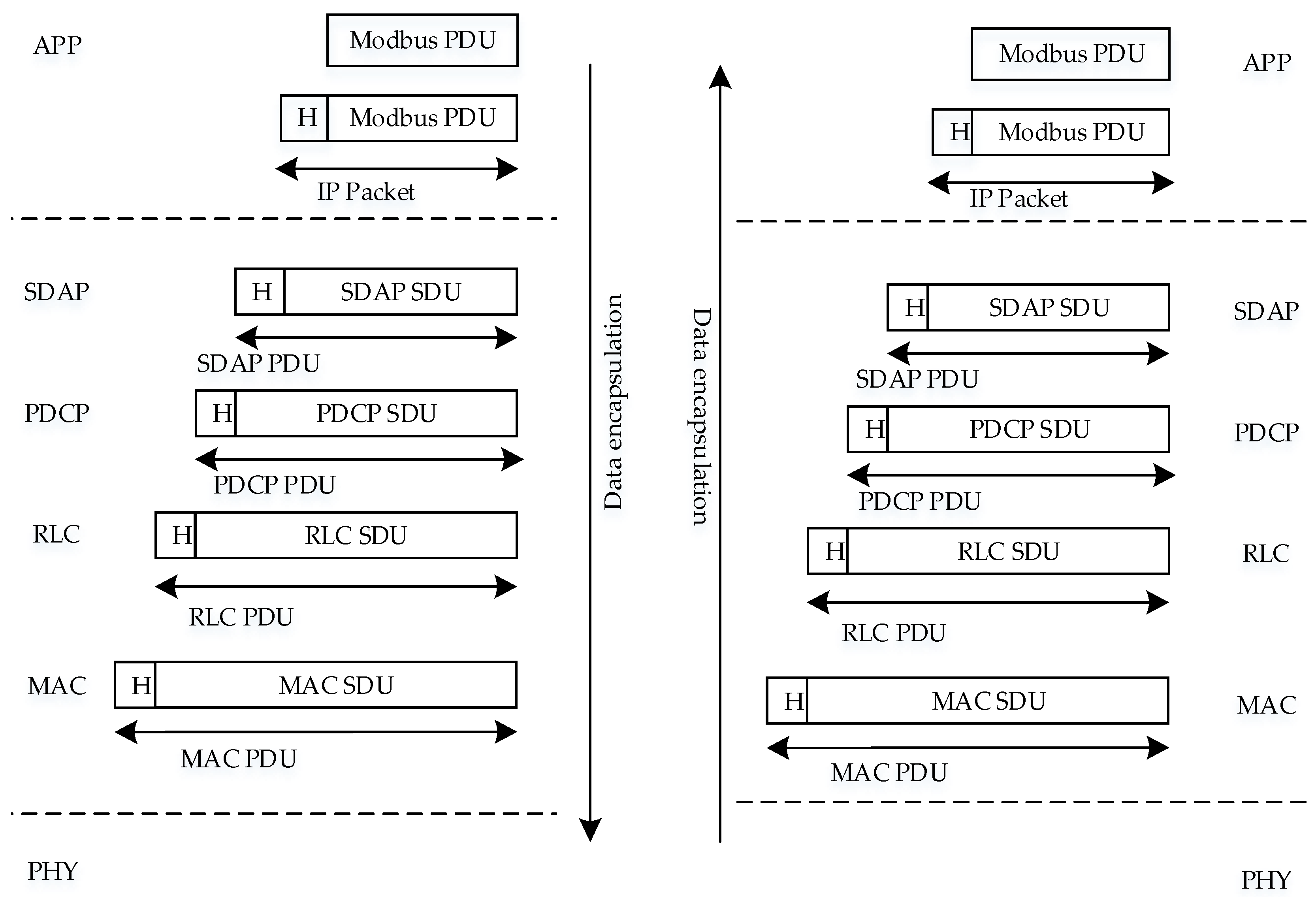
A wireless channel is used to transmit 5G data, where the ADU of 5G is divided into multiple fields according to the complex protocol stack. The 5G New Radio (NR) protocol stack is divided into the control plane protocol stack and the user plane protocol stack [29]. Therefore, we sent data from terminal side to the service data application protocol (SDAP) sublayer of the data link layer in the user plane protocol stack through the TCP/IP protocol. The uplink frame structure of the data link layer in the user plane protocol stack is illustrated in Figure 3. The SDAP frame is divided into four fields, including 1 bit protocol data unit (PDU) type identifier, 1 bit reserved bit, 6 bits QoS flow identifier, and N bits data. Other sublayer fields are divided in the same way. Then, we make data successively pass through the packet data aggregation protocol (PDCP) sublayer, radio link control (RLC) sublayer, media access control (MAC) sublayer, and physical layer (PHY).
In general, the physical layer frame structure of wireless communication technology is a fixed structure because the previous application environment does not have high requirements for frame structure. Nowadays, 5G technology is required to be used in various services. In order to cope with various complex scenarios, researchers have redefined the physical layer frame structure of the 5G NR and combined fixed subframes with variable time slots to meet dynamic business development needs and improve network utilization [30].

4. Protocol Adaptation for Modbus and 5G

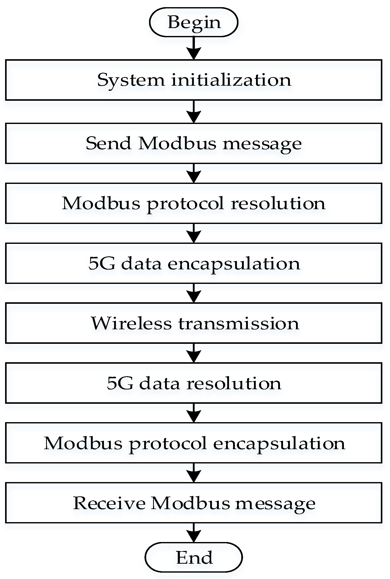
By analyzing the characteristics for the frame structure of Modbus RTU, Modbus TCP and 5G in Section 3, we propose the protocol adaptation scheme in Figure 4 to establish the end-to-end link for Modbus and 5G. Specifically, we first judge the message’s frame structure and screen out the valid data. Then, we resolve the valid data and extract part of the data for storage. After that, we encapsulate and transmit the stored data. Lastly, we decapsulate the 5G packet and recover the complete frame structure of the Modbus protocol.
In the following, we will introduce the protocol adaptation process for Modbus RTU and Modbus TCP in detail.

4.1. Protocol Adaptation for Modbus RTU and 5G

According to the basic process in Figure 4, the protocol adaptation between Modbus RTU and 5G further includes Modbus RTU frame structure judgment, message data resolution and storage, 5G data encapsulation and decapsulation, and Modbus RTU frame structure recovery.
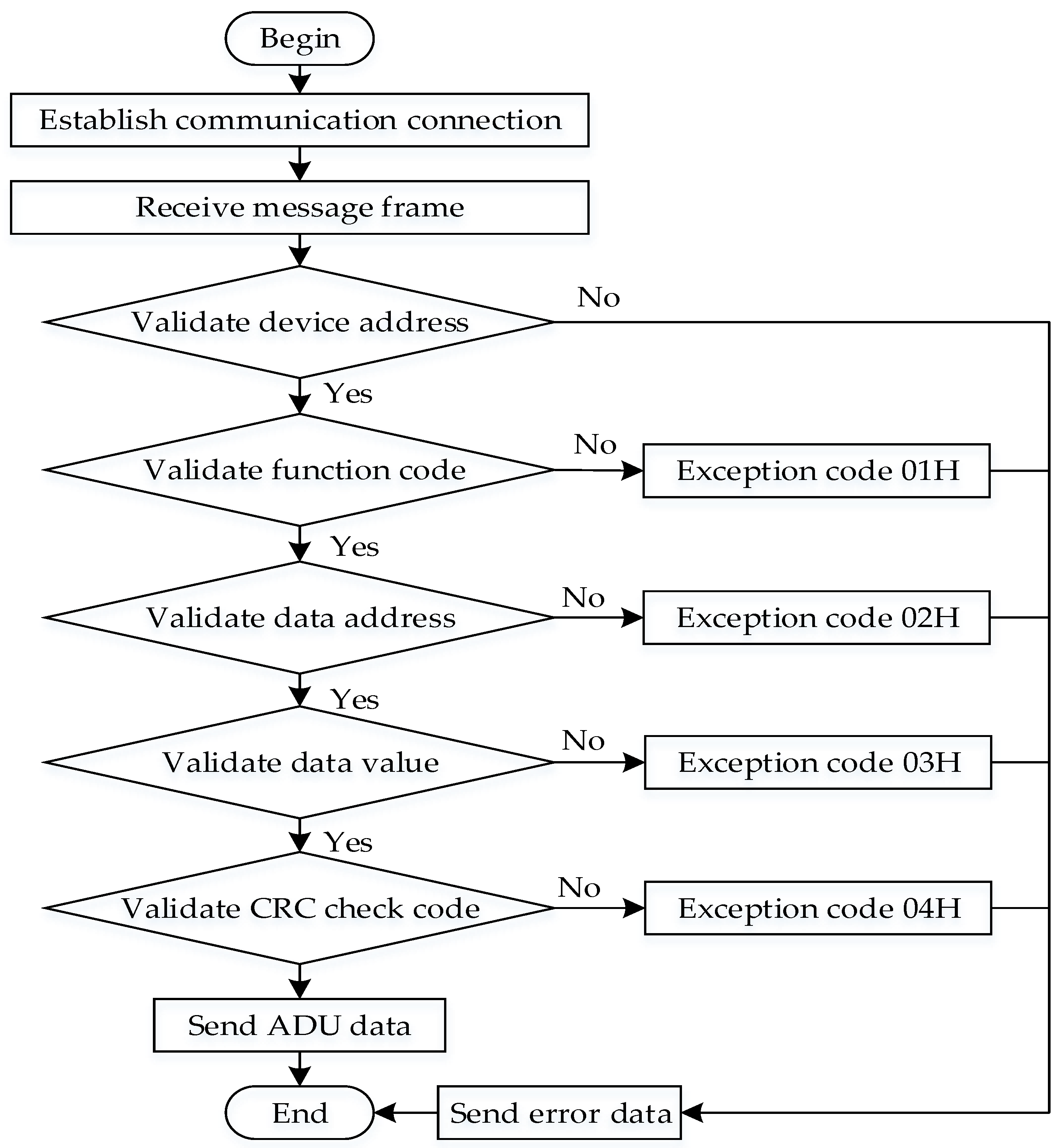
Figure 5 depicts the Modbus RTU data judgment process.
The first step is to judge the Modbus RTU message frame. First of all, we must judge the correctness of the device address. If it is not correct, the message is discarded. Otherwise, we continue judging the function code. If the function code is unable to perform any function, we send an exception response with the exception code 01. Then, we confirm the data address. If the data address is not allowed by the slave device, we send an exception response with the exception code 02. Next, for the value of the data area which does not conform to the normal data range of the device, the exception code 03 is sent. If it is on the contrary, we continue judging the check code. Finally, the CRC check code in the message is consistent with the check code generated by logical operation; we try to execute different operation tasks according to the function code. If not, we send an exception response with the exception code 04, meaning that the slave device makes an unrecoverable error when we execute various tasks.
The second step is to resolve the valid message. First, we resolve the frame structure according to number of bytes each field occupies. After that, we can obtain the destination device address code, PDU data, and CRC check code in Modbus RTU. Then, we separately extract and store the PDU data.
The third step is to encapsulate the resolved data by the 5G protocol stack and transmit it through the wireless channel. In the fourth step, we resolve the PDU data of the 5G data package in the receiver according to the reverse process of the 5G data encapsulation. In the fifth step, we add the missing Modbus RTU frame structure field. We need to add the destination device address to the PDU data first and then perform a logical operation on the device address and the PDU data to obtain the CRC check code of the last 2 bytes.

4.2. Protocol Adaptation for Modbus TCP and 5G

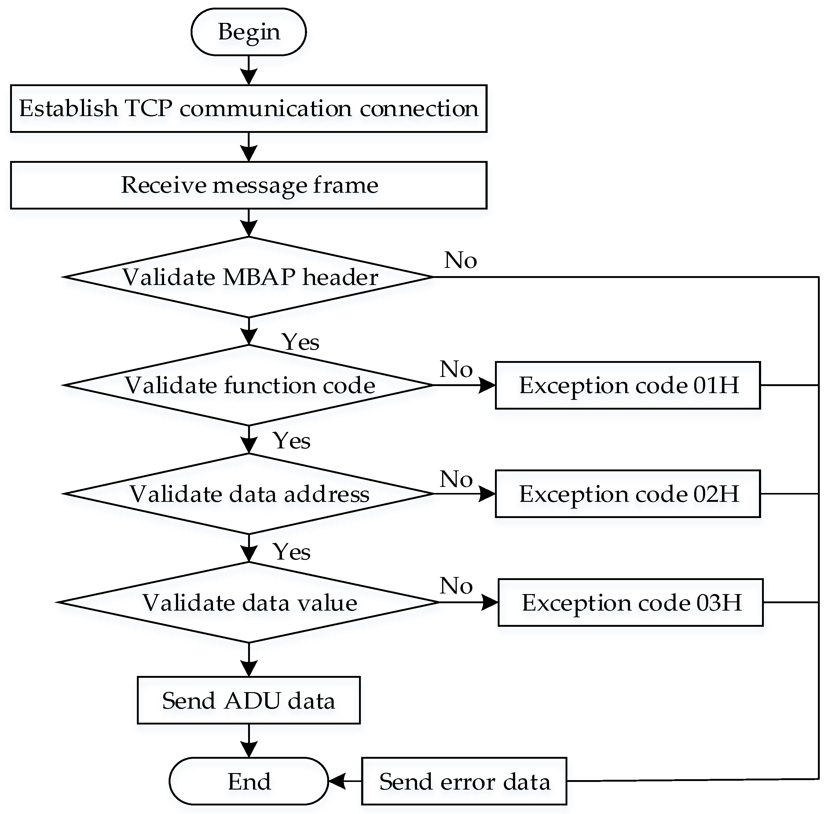
In the same way, we detail the protocol adaptation between Modbus TCP and 5G. The Modbus data judgment process is shown in Figure 6. In the first step, we judge that the transaction identifier, protocol identifier, and unit identifier in the MBAP belong to the Modbus TCP protocol. Otherwise, we discard this data and wait for the next frame message. Then, we verify the correctness of the function code, data address, and data scope in turn. If not correct, we send the 01, 02, and 03 exception codes with the same meaning as Modbus RTU. Secondly, we resolve the valid data into the MBAP message header and PDU data. Thereafter, we separately extract and store the PDU data. In the third step, we encapsulate the resolved data by the 5G protocol stack and transmit it through the antenna. Fourth, we resolve the PDU data of the 5G data package in the receiver, according to the reverse process of 5G data encapsulation. The fifth step is to add the missing MBAP field.
In the above processes, we convert the Modbus data into the 5G data according to the 5G NR protocol stack. We obtain the Modbus PDU data sequentially through the SDAP sublayer, PDCP sublayer, RLC sublayer, MAC sublayer, and physical layer in the user plane protocol stack data link layer. The 5G data encapsulation and decapsulation process is presented in Figure 7. First, we send the Modbus PDU data to the application layer through a TCP/IP protocol. After that, we observe that each IP packet is given a label and perform the mapping of QoS flows to radio bearers in the SDAP [31] sublayer. Subsequently, the data are transmitted to the PDCP sublayer, which compresses, encrypts and protects the IP header [31]. Next, the data are added to the RLC header and sent in sequence according to different logical channels. We can also request to retransmit erroneous data. Afterward, we transmit the data to the MAC sublayer for selecting the transmission blocks and ensuring the instantaneous rate according to the link adaptive mechanism [32]. Ultimately, we encode, modulate, and check the wrong data.

5. Prototype Development for Wireless PLC

As can be seen from Section 3, we use two protocols to combine with 5G, but the transmission interfaces used by these two protocols lack conformity. Therefore, we design 5G-based wireless PLC prototype systems for both Modbus RTU and Modbus TCP.

5.1. Hardware Architecture

The industrial wireless control system includes three parts: the PLC controller, the 5G-based protocol adapter, and the actuator. The PLC controller transmits and receives the Modbus messages. The protocol adapter resolves and converts the protocol between 5G and Modbus. The actuator receives the instruction of the PLC controller and realizes the corresponding operation through the instruction.
As Modbus RTU and Modbus TCP utilize different transmission media, we choose the PLC controller containing the RS-485 serial port and the Ethernet port. Fully considering the advantages of smaller size, lower power consumption, lower cost and higher performance, we use ARM Cortex-A72 architecture as the system on a chip (SoC), where the Linux operating system is utilized as the underlying driver. Additionally, the 5G module in the protocol adapter is an industrial-level module. In other words, we have a 5G module that uses the sub-6GH band with strong signal penetration, which also supports LTE-A and WCDMA bands at the same time. It has two modes of non-standalone (NSA) networking and standalone (SA) networking. Theoretically, the maximum uplink and downlink transmission rates in 5G SA mode are 1 Gbps and 2 Gbps, respectively. In contrast, the maximum uplink and downlink transmission rates in 5G NSA mode are 575 Mbps and 2.2 Gbps, respectively. We also choose equipment with small volume, large power, and low noise as the actuator.

5.1.1. Prototyping for Modbus RTU

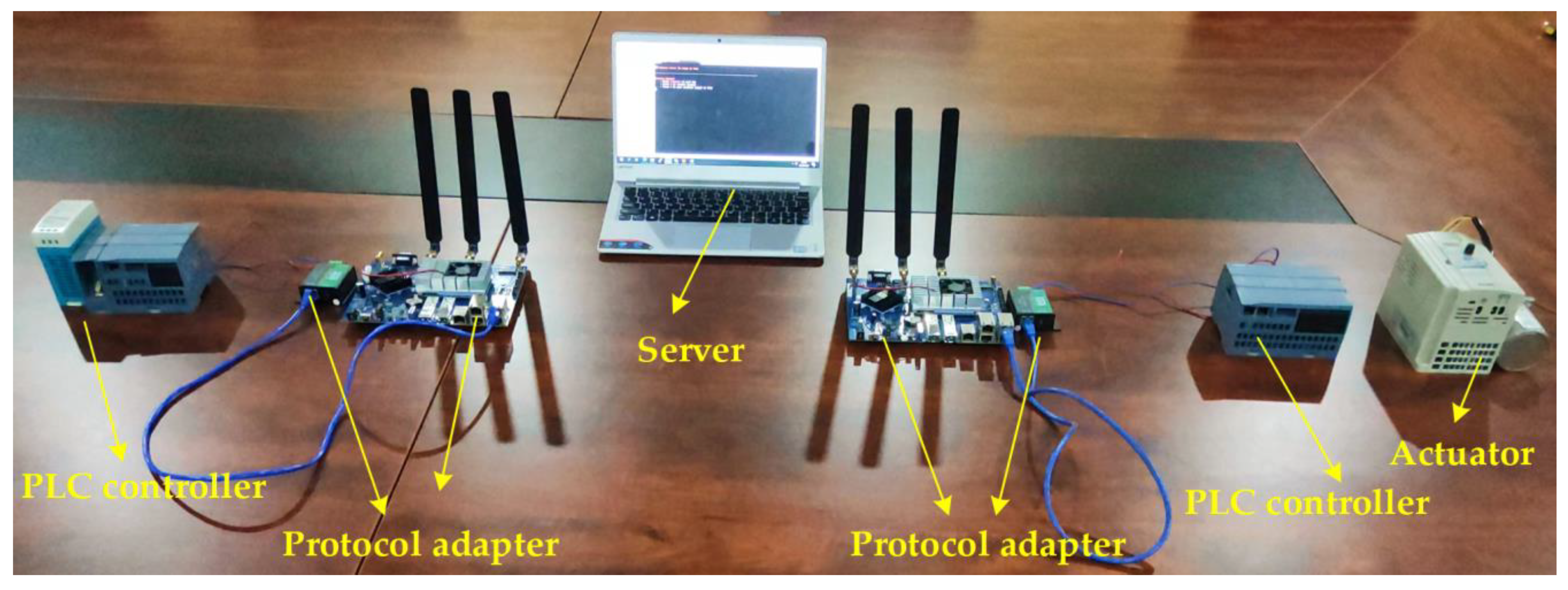
The structure of the wireless PLC for Modbus RTU is presented in Figure 8 and Figure 9. In this system, we connect a transmitter PLC controller with the protocol adapter and connect a receiver PLC controller with the protocol adapter and the actuator by the RS-485 bus. The protocol adapter consists of a RS-485 bus to the Ethernet module, Ethernet port, storage unit, 5G module and radio frequency unit. That is, we use the RS-485 bus to the Ethernet module as the medium to convert Modbus RTU data and the storage unit to store, read, and write data. We also make the 5G module encapsulate and decapsulate data, and we use the radio frequency unit for transmitting data to the 5G base station.

5.1.2. Prototyping for Modbus TCP

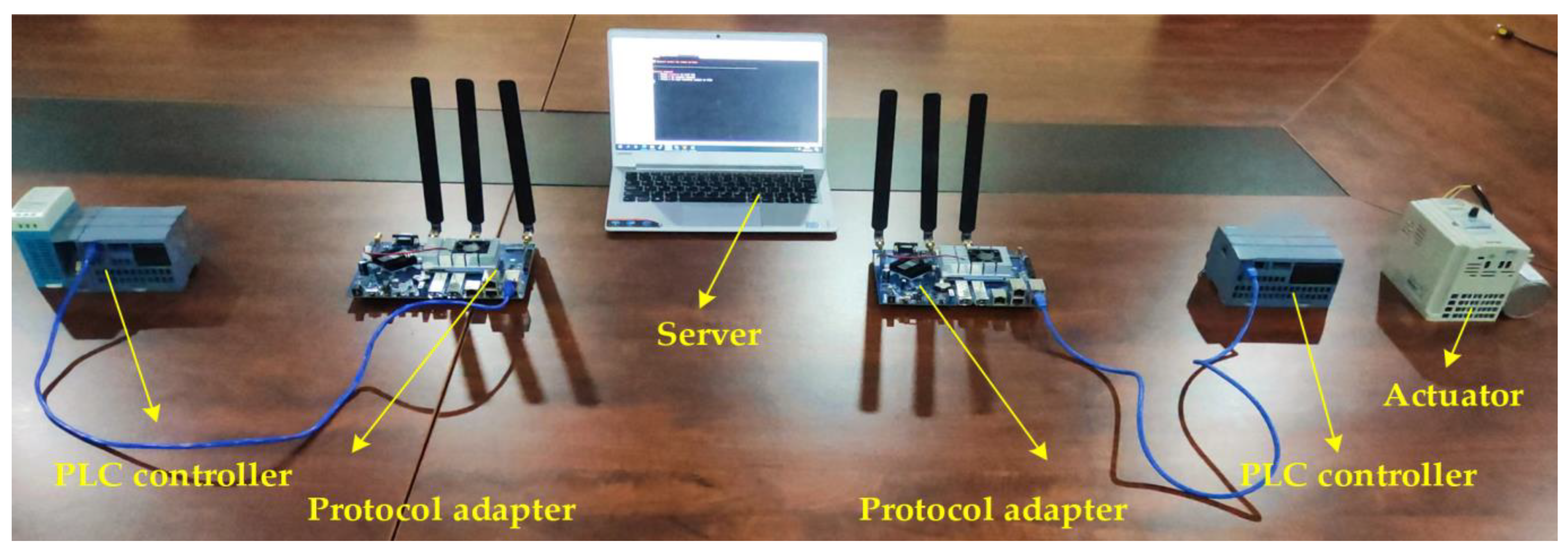
The structure of the wireless PLC for Modbus RTU is depicted in Figure 10 and Figure 11. In the same way, we connect the transmitter PLC controller with the protocol adapter and connect the receiver PLC controller with the protocol adapter and the actuator by the Ethernet cable. However, we design the prototype system structure of Modbus TCP differently from the prototype system structure of Modbus RTU. The protocol adapter only consists of the Ethernet port, storage unit, 5G module, and radio frequency unit. Similarly, we also use the whole protocol adapter for completing the functions of data reception, data resolution, data storage, data transmission, data encapsulation, and data decapsulation.
Comparing Figure 8 with Figure 10, we can observe that the main difference for Modbus RTU and Modbus TCP lies in the application of the RS-485 to Ethernet module. This is mainly because the existing 5G module does not own the RS-485 port, which demands the conversion between RS-485 and Ethernet.

5.2. Software Design

The software implementation of protocol adaptation is an important step to complete the functions of the whole 5G system. Therefore, based on the hardware system architecture designed in Section 5.1, the overall architecture of the software implementation is built on an Ubuntu system. Thus, we realize register configuration and cache read-write function under the driver of the bottom layer. Then, the functions of the Modbus protocol data link layer and application layer are realized. Next, we convert the Modbus data into the 5G data in the data link layer. Finally, we use network address translation technology to automatically match the IP address and realize the two-way transmission of the data stream. The software architecture of the PLC wireless prototype system is shown in Figure 12.
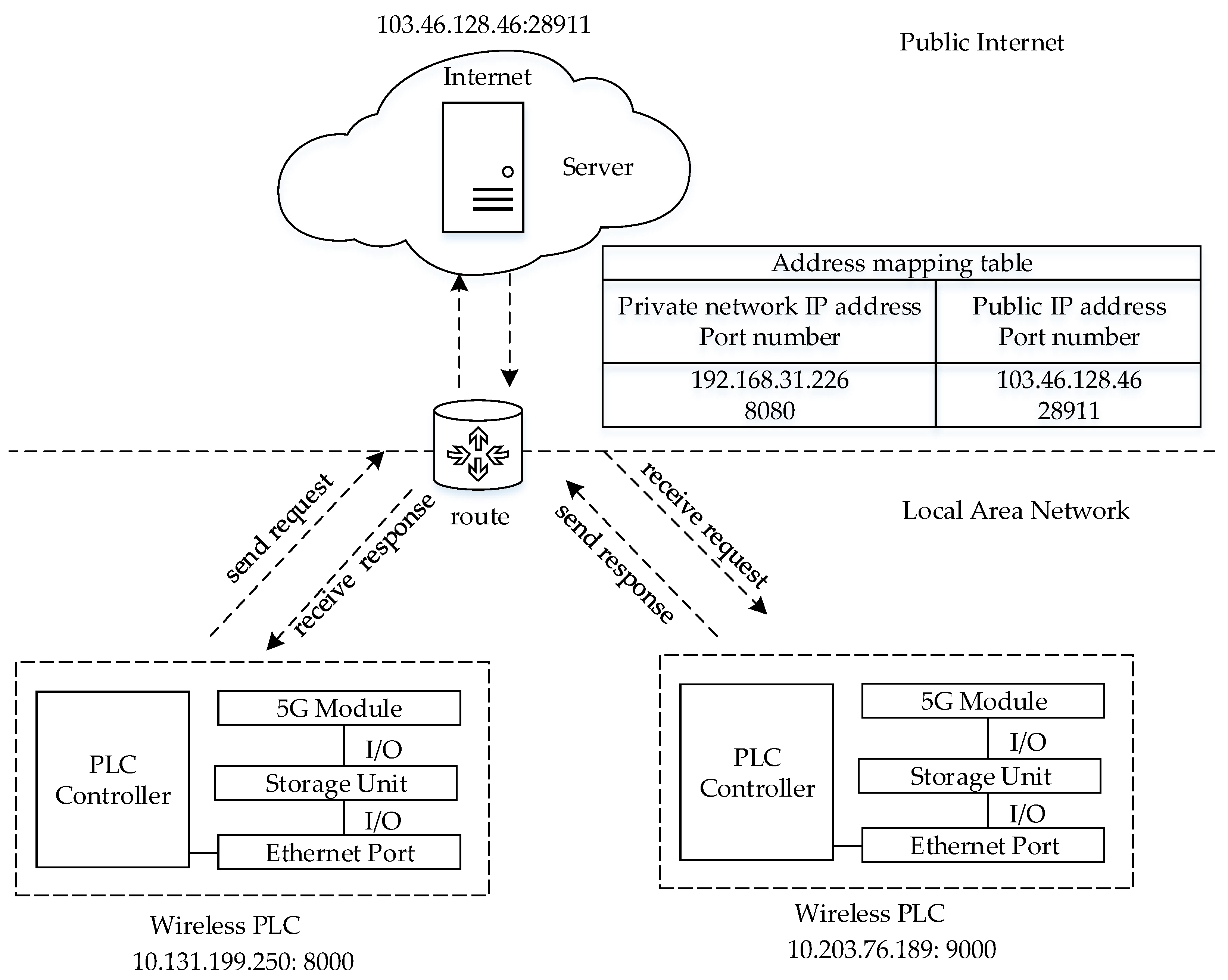
The network address translation technology mentioned above can automatically match the 5G modules of the sender and the receiver. That is, the local area network IP address is converted into the public network IP address. In this paper, we convert the private IP address and port number of a fixed terminal into the public IP address and port number. Next, we send a connection request to the public network, and the router receives the request message from the public network. Later, the router automatically queries the address mapping table and converts the IP address and port number of the public network message into the IP address and port number of the fixed terminal. Eventually, we can establish the connection of the terminals with the server, and the server is used as a transfer station to realize the mutual communication between terminals. The network address translation process of the system is presented in Figure 13.
As mentioned earlier, we need to realize the software of the two systems respectively.
(1)
Modbus TCP data. The first step is that we use the bind function to make the slave protocol adapter bind the local IP address and port number and the master protocol adapter bind the IP address and port number of the slave PLC controller. In the second step, we use the address mapping function to apply for memory to store register values. In the third step, we use the monitor function to make the slave protocol adapter wait for the connection of the master PLC controller and use the connection function to establish the connection of the master protocol adapter and the slave PLC controller. Afterward, we use the analysis function to resolve the Modbus TCP data and store the PDU data into a storage unit. The next step is to convert the Modbus PDU data into the 5G data through 5G modules. Then, we resolve the 5G data with analysis function. Next, we add the MBAP field to the Modbus PDU data and use the register write function to store data into the hold register of the PLC controller by the master protocol adapter. Figure 14 illustrates the implementation process of the Modbus TCP software.
(2)
Modbus RTU data; the protocol adapter is connected to the PLC controller through the Ethernet conversion module. Therefore, we use the socket form to realize data reception, data resolution, data storage, data conversion, and data transmission.
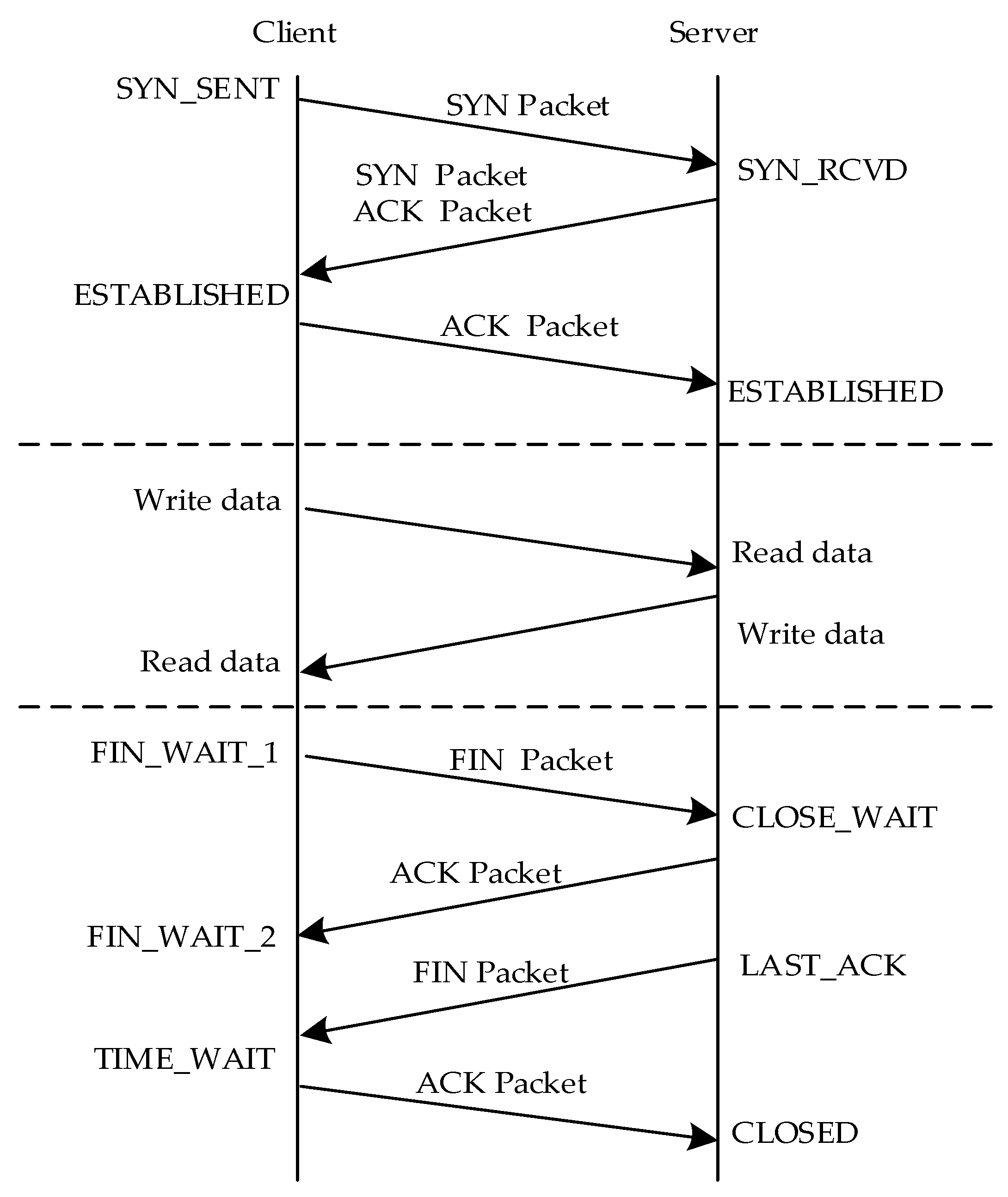
Specifically, we use the 5G module to send and receive data in the socket form based on the TCP/IP protocol, which does not affect the communication quality or change the original data content. Under normal circumstances, it is a single-process transmission, but the system has multiple clients. As a result, the system creates multi-thread transmission, in which data are processed in a sub-thread, and the main thread is only responsible for monitoring the connection of the client. Additionally, there is a time interaction sequencer between the client and the server in the process of data transmission. Figure 15 shows the data transmission sequence process.

6. Experimental Evaluation

6.1. Experiment Setup

This section conducts physical experiments and results analysis on the 5G-based wireless PLC prototype. The whole test process is carried out in an indoor environment. Without loss of generality, we choose the SIMATIC S7-1215C as the PLC controller. When the PLC controller is used to transmit Modbus TCP protocol, its port number is set to 502. The protocol adapter uses the Layerscape 1046 A multi-core communication processor which supports four Cortex-A72 cores. The 5G module is an industrial-level RM500U-CN module supporting Release 16 standard, with rich network protocols, and multiple industrial standard interfaces. We use a China Mobile SIM card for dial-up Internet access and use the VFD-M model with the RS-485 port and the Modbus protocol as the actuator. The actuator has four state variations, namely operation, speed 1000 r/min, speed 6000 r/min, and stop. By observing the variation of the actuator state, we can judge the success of instruction.
Under different protocol adaptation systems, we respectively carry out four groups of comparison experiments on end-to-end delay and reliability. These experiments compare the protocol adaptation scheme with protocol transparent transmission without resolution and conversion. For the end-to-end delay, we calculate the differential value of the timestamp between the test node of the transmitter PLC controller and the receiver PLC controller. For the reliability test, we calculate the ratio of the number of messages received by the receiver PLC controller to the number of messages sent by the transmitter PLC controller by changing the cycle time of instructions. In the end, by analyzing the results, the one with better performance in the four groups of experiments is compared.

6.2. Result Analysis

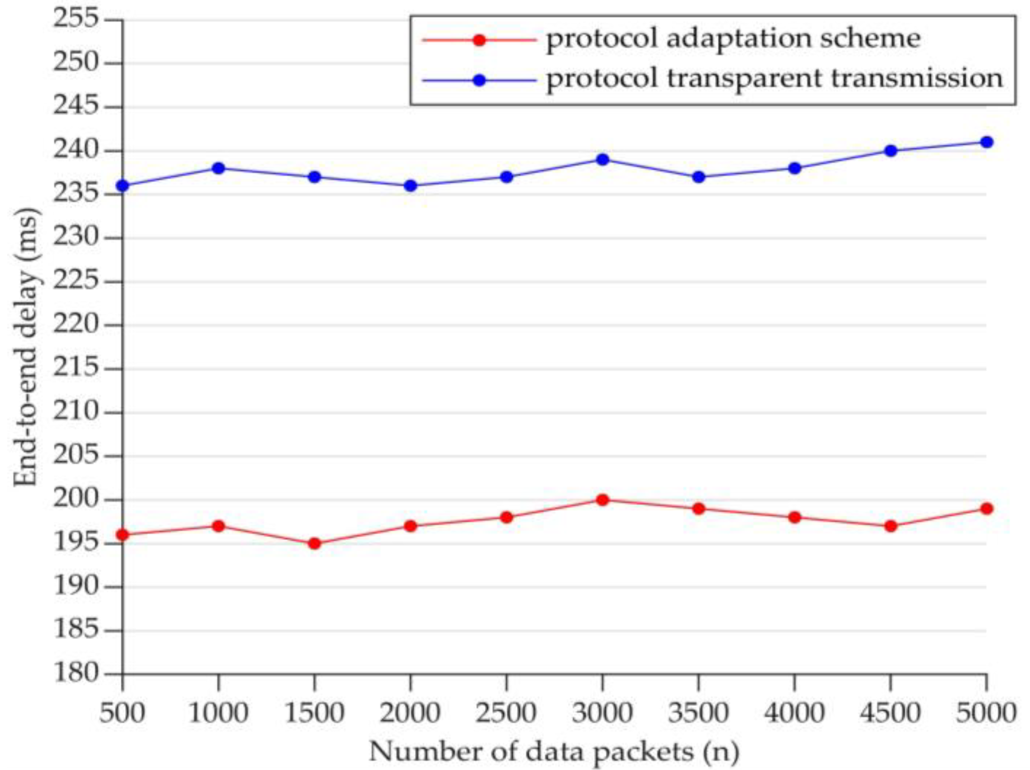
Figure 16 compares the end-to-end delay for Modbus RTU and 5G by the protocol adaptation scheme and transparent transmission. It can be seen from the figure that the end-to-end delay of using the protocol adaptation scheme is lower than that of using protocol transparent transmission.
Figure 17 compares the end-to-end delay for Modbus TCP and 5G by the protocol adaptation scheme and transparent transmission. As observed from the figure, the end-to-end delay of using the protocol adaptation scheme is also lower than that of using protocol transparent transmission.
Furthermore, by comparing Figure 16 and Figure 17, it can be found that the end-to-end delay fluctuates up and down. This instability may be caused by server congestion as a transfer station or instability of commercial 5G. Moreover, when we transmit the same magnitude packets, the end-to-end delay differential value of Modbus RTU data transmitted by two methods is smaller than that of Modbus TCP data transmitted by two methods. The reason should be that the Modbus RTU data resolved by the protocol adaptation scheme has a 3 bytes differential value compared with the original Modbus RTU data. However, the Modbus TCP data resolved by the protocol adaptation scheme have a 7 bytes differential value compared with the original Modbus TCP data.
Figure 18 presents the end-to-end delay comparison results of the protocol adaptation scheme between Modbus RTU/Modbus TCP and 5G. From the figure, it can be observed that the end-to-end delay of transmitting Modbus TCP in the protocol adaptation scheme is lower than that of transmitting Modbus RTU in the protocol adaptation scheme when we transmit the same data length. Accordingly, by analyzing and comparing the end-to-end delay of four groups of experiments, it can be found that the end-to-end delay of the protocol adaptation scheme is the best between Modbus TCP and 5G.
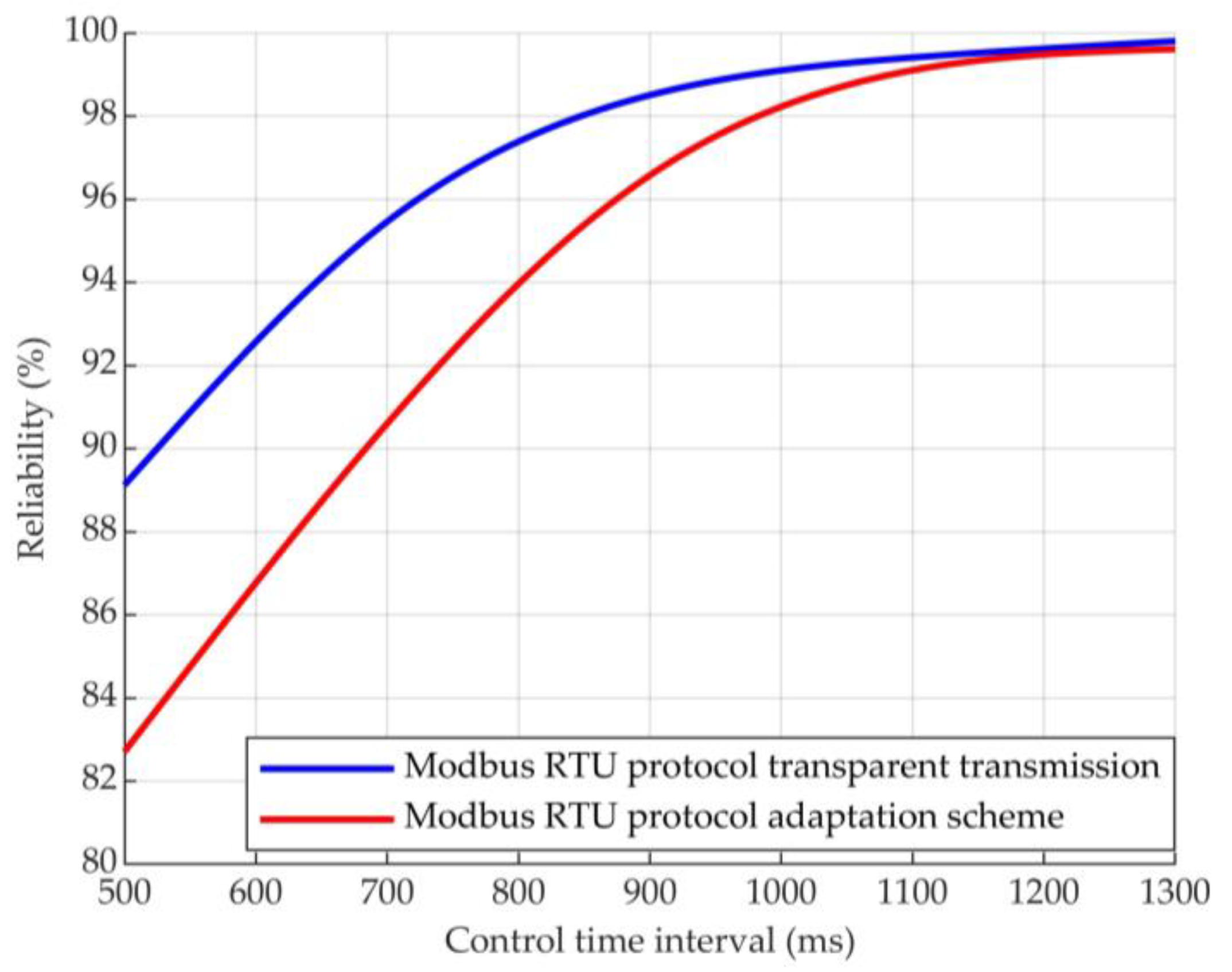
To test the reliability of the wireless PLC prototype, we fit the discrete data of five known test nodes into a curve by the smoothing spline function. By fitting, we can obtain the estimated values of other unknown test nodes. Figure 19 illustrates the reliability comparison results of Modbus RTU and 5G protocol adaptation. According to this figure, the reliability of the Modbus RTU protocol adaptation scheme is lower than that of the Modbus RTU protocol transparent transmission. This is mainly because transparent transmission does not resolve the protocol data and directly encapsulate the data as 5G data.
Figure 20 depicts the reliability comparison results of Modbus TCP and 5G protocol adaptation. Likewise, the reliability of the Modbus TCP protocol adaptation scheme is lower than that of the Modbus TCP protocol transparent transmission.
Moreover, based on the overall comparison of Figure 19 and Figure 20, it can be found that with the increase of sending instructions time interval, the reliability is higher.
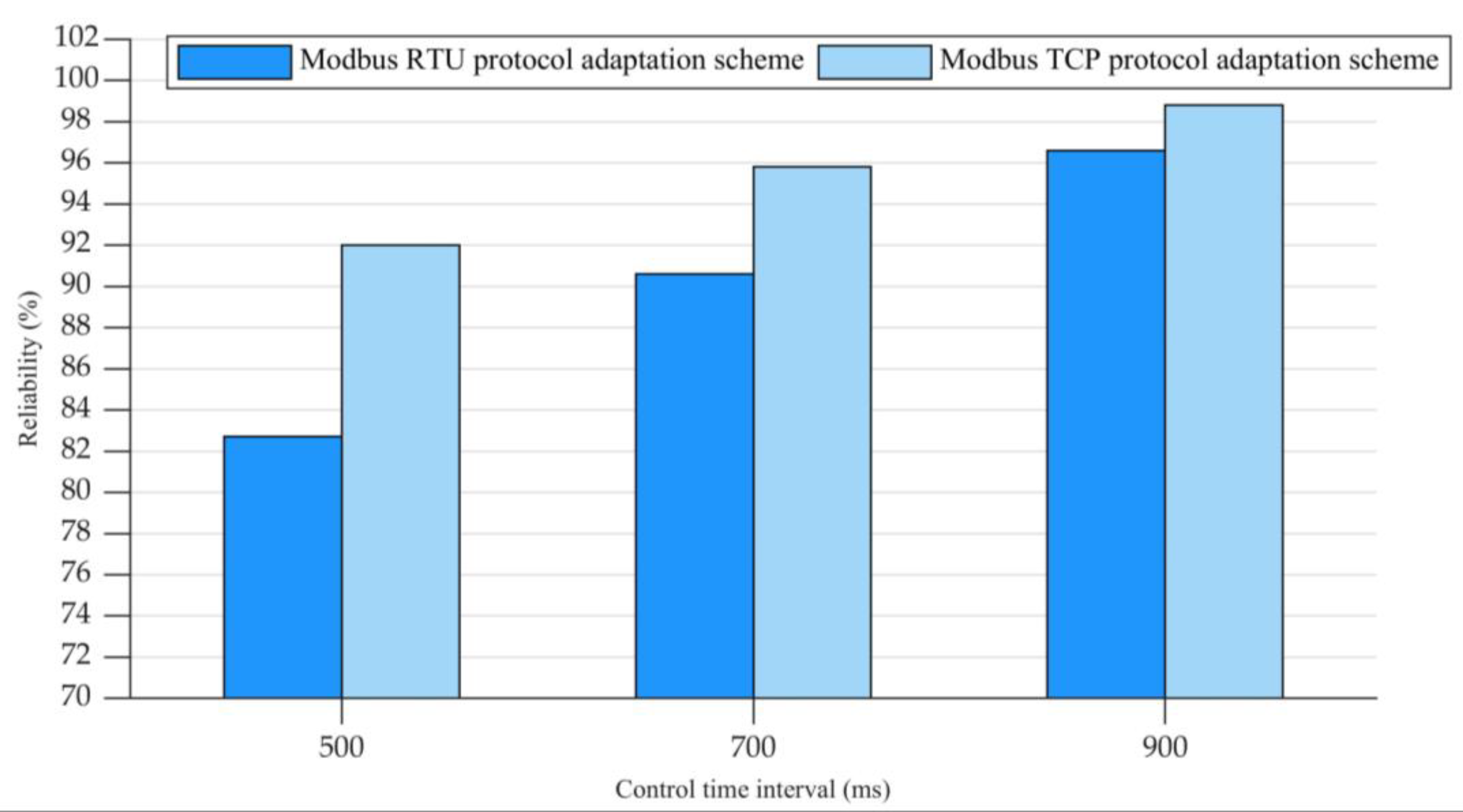
To further analyze the reliability, we take three test nodes to compare the reliability of the protocol adaptation scheme between Modbus RTU/Modbus TCP and 5G. As can be observed from Figure 21, the reliability of the Modbus TCP protocol adaptation scheme is higher than that of the Modbus RTU protocol adaptation scheme. By analyzing and comparing the reliability of four groups of experiments, it can be found that the reliability of the protocol transparent transmission is the highest between Modbus TCP and 5G.

7. Conclusions

In this paper, with the analysis of the network structure and the protocol characteristics of Modbus and 5G protocols, we proposed a protocol adaptation scheme that resolves the Modbus protocol and converts the data between Modbus and 5G. On this basis, we designed a wireless PLC prototype and performed extensive experiments to evaluate the end-to-end delay and reliability. The results showed that the latency of the protocol adaptation is smaller than that of the protocol transparent transmission, while there is a small reliability loss. Meanwhile, both the speed and reliability of Modbus TCP adaptation are better than those of Modbus RTU adaptation. Generally, the performance of the wireless PLC prototype can meet the basic requirements as a Modbus-based wired PLC, such as remote control and automated production.
However, there are still some challenges that should well addressed in future works. First, the configuration of the wireless PLC prototype should be further optimized since automation engineers generally do not have extensive knowledge on Linux programming. Second, the current wireless PLC prototype completely depends on commercial 5G modules and must be operated on a licensed band. Thus, we can develop a software-defined prototype to operate on unlicensed band for self-organized networking. Third, the prototype should be tested in a practical factory with hash environment. Only in this way can the wireless PLC prototype really be utilized to enhance intelligent manufacturing while accelerating the applications of 5G. Last but not least, with 5G, the energy supplements and energy efficiency should be considered, which will enable wireless PLC to achieve flexible deployments. Furthermore, the wireless PLC prototype with respect to latency, reliability, spectrum, and energy efficiency should be continuously optimized to satisfy critical industrial control applications in the 6G era.

Author Contributions

Conceptualization, C.X. (Chi Xu); methodology, X.D., Y.T.; software, X.D., Y.T.; validation, X.D., Y.T.; formal analysis, X.D., X.J.; investigation, X.L., L.L.; Writing—Original draft preparation, X.D., C.X. (Chi Xu); Writing—Review and editing, C.X. (Changqing Xia); supervision, C.X. (Chi Xu), X.L. All authors have read and agreed to the published version of the manuscript.

Funding

This research was funded by National Key Research and Development Program of China under Grant 2020YFB1710900, National Natural Science Foundation of China under Grants 62173322, 92267108, 62133014, 61972389, 61903356, and Youth Innovation Promotion Association CAS under Grants 2019202, 2020207, Y2021062.

Data Availability Statement

Not applicable.

Conflicts of Interest

The authors declare no conflict of interest.

Abbreviations

3GPP3th Generation Partnership Project
5G-ACIA5G Alliance for Connected Industries and Automation
ADUApplication Data Unit
FSoEFailSafe Over EtherCAT
ICNsIndustrial Control Networks
IWNIndustrial Wireless Network
ITUInternational Telecommunication Union
MBAPModbus Application Protocol
MACMedia Access Control
NRNew Radio
NSANon-Standalone
PLCProgrammable Logic Controller
PDUProtocol Data Unit
PDCPPacket Data Convergence Protocol
PHYPhysical Layer
QoSQuality of Service
RTURemote Terminal Unit
RLCRadio Link Control
SDAPService Data Adaption Protocol
SoCSystem on Chip
SAStandalone
TCPTransmission Control Protocol
URLLCUltra-Reliable and Low-Latency Communication

References

  1. Diao, Z.; Sun, F. Application of Internet of Things in Smart Factories under the Background of Industry 4.0 and 5G Communication Technology. Math. Probl. Eng. 2022, 2022, 4417620. [Google Scholar] [CrossRef]
  2. Yu, H.; Zeng, P.; Xu, C. Industrial Wireless Control Networks: From WIA to the Future. Engineering 2022, 8, 18–24. [Google Scholar] [CrossRef]
  3. Müller, T.; Doran, H.D. Protecting PROFINET cyclic real-time traffic: A performance evaluation and verification platform. In Proceedings of the 2018 14th IEEE International Workshop on Factory Communication Systems (WFCS), Imperia, Italy, 13–15 June 2018; pp. 1–4. [Google Scholar]
  4. Au, E. A Short Update on 3GPP Release 16 and Release 17 [Standards]. IEEE Veh. Technol. Mag. 2020, 15, 160. [Google Scholar] [CrossRef]
  5. Xu, C.; Zeng, P.; Yu, H.; Jin, X.; Xia, C. WIA-NR: Ultra-reliable low-latency communication for industrial wireless control networks over unlicensed bands. IEEE Netw. 2021, 35, 258–265. [Google Scholar] [CrossRef]
  6. Jaloudi, S. Communication protocols of an industrial Internet of things environment: A comparative study. Future Internet 2019, 11, 66. [Google Scholar] [CrossRef] [Green Version]
  7. González, I.; Calderón, A.J.; Portalo, J.M. Innovative multi-layered architecture for heterogeneous automation and monitoring systems: Application case of a photovoltaic smart microgrid. Sustainability 2021, 13, 2234. [Google Scholar] [CrossRef]
  8. Brito, I.B.; Jr, R.T. Development of an open-source testbed based on the Modbus protocol for cybersecurity analysis of nuclear power plants. Appl. Sci. 2022, 12, 7942. [Google Scholar] [CrossRef]
  9. Wei, M.; Li, C.; Li, C. An IPv6 Internet Accessing Architecture and Approach for Industrial Wireless Network. In Proceedings of the 2020 14th International Conference on Ubiquitous Information Management and Communication (IMCOM), Taichung, Taiwan, 3–5 January 2020; pp. 1–6. [Google Scholar]
  10. Gil, S.; Zapata-Madrigal, G.D.; García-Sierra, R.; Cruz Salazar, L.A. Converging IoT protocols for the data integration of automation systems in the electrical industry. J. Electr. Syst. Inf. Technol. 2022, 9, 1. [Google Scholar] [CrossRef]
  11. Kulik, V.; Kirichek, R. The Heterogeneous Gateways in the Industrial Internet of Things. In Proceedings of the 2018 10th International Congress on Ultra Modern Telecommunications and Control Systems and Workshops (ICUMT), Moscow, Russia, 5–9 November 2018; pp. 1–5. [Google Scholar]
  12. Shi, H.; Niu, L.; Sun, J. Construction of Industrial Internet of Things Based on MQTT and OPC UA Protocols. In Proceedings of the 2020 IEEE International Conference on Artificial Intelligence and Computer Applications (ICAICA), Dalian, China, 27–29 June 2020; pp. 1263–1267. [Google Scholar]
  13. Silva, C.R.M.; Silva, F.A.C.M. An IoT Gateway for Modbus and MQTT Integration. In Proceedings of the 2019 SBMO/IEEE MTT-S International Microwave and Optoelectronics Conference (IMOC), Aveiro, Portugal, 10–14 November 2019; pp. 1–3. [Google Scholar]
  14. Botero, J.G.Z.; Cuartas, J.A.H.; Garces, S.I.S. Communication Profibus-ZigBee using low cost gateway. In Proceedings of the 2015 IEEE 20th Conference on Emerging Technologies & Factory Automation (ETFA), Luxembourg, 8–11 September 2015; pp. 1–4. [Google Scholar]
  15. Ye, Y.t.; Lei, H.d. Wireless industrial communication system based on Profibus-DP and ZigBee. In Proceedings of the 2016 11th International Conference on Computer Science & Education (ICCSE), Nagoya, Japan, 23–25 August 2016; pp. 666–669. [Google Scholar]
  16. Zhou, Y.; Xiao, W.; Liu, M.; Li, X. Design of the embedded gateway for 4G and PROFIBUS-DP based on FPGA. In Proceedings of the 2017 3rd IEEE International Conference on Computer and Communications (ICCC), Chengdu, China, 13–16 December 2017; pp. 748–752. [Google Scholar]
  17. Wu, X.; Xie, L. On the Wireless Extension of EtherCAT Networks. In Proceedings of the 2017 IEEE 42nd Conference on Local Computer Networks (LCN), Singapore, 9–12 October 2017; pp. 235–238. [Google Scholar]
  18. Morato, A.; Vitturi, S.; Cenedese, A.; Fadel, G.; Tramarin, F. The Fail Safe over EtherCAT (FSoE) protocol implemented on the IEEE 802.11 WLAN. In Proceedings of the 2019 24th IEEE International Conference on Emerging Technologies and Factory Automation (ETFA), Zaragoza, Spain, 10–13 September 2019; pp. 1163–1170. [Google Scholar]
  19. Wu, X.; Xie, L. On the Wireless Extension of PROFINET Networks. In Proceedings of the 2019 IEEE VTS Asia Pacific Wireless Communications Symposium (APWCS), Singapore, 28–30 August 2019; pp. 1–5. [Google Scholar]
  20. Trancă, D.C.; Pălăcean, A.V.; Mihu, A.C.; Rosner, D. ZigBee based wireless modbus aggregator for intelligent industrial facilities. In Proceedings of the 2017 25th Telecommunication Forum (TELFOR), Belgrade, Serbia, 21–22 November2017; pp. 1–4. [Google Scholar]
  21. Yang, M.; Lim, S.; Oh, S.M.; Shin, J. An Uplink Transmission Scheme for TSN Service in 5G Industrial IoT. In Proceedings of the 2020 International Conference on Information and Communication Technology Convergence (ICTC), Jeju-do, Republic of Korea, 21–23 October 2020; pp. 902–904. [Google Scholar]
  22. Nikhileswar, K.; Prabhu, K.; Cavalcanti, D.; Regev, A. Time-Sensitive Networking Over 5G for Industrial Control Systems. In Proceedings of the 2022 IEEE 27th International Conference on Emerging Technologies and Factory Automation (ETFA), Stuttgart, Germany, 6–9 September 2022; pp. 1–8. [Google Scholar]
  23. Satka, Z.; Pantzar, D.; Magnusson, A.; Ashjaei, M.; Fotouhi, H.; Sjödin, M.; Daneshtalab, M.; Mubeen, S. Developing a Translation Technique for Converged TSN-5G Communication. In Proceedings of the 2022 IEEE 18th International Conference on Factory Communication Systems (WFCS), Pavia, Italy, 27–29 April 2022; pp. 1–8. [Google Scholar]
  24. Jiang, X.; Pang, Z.; Zhan, M.; Dzung, D.; Luvisotto, M.; Fischione, C. Packet Detection by a Single OFDM Symbol in URLLC for Critical Industrial Control: A Realistic Study. IEEE J. Sel. Areas Commun. 2019, 37, 933–946. [Google Scholar] [CrossRef] [Green Version]
  25. Khoshnevisan, M.; Joseph, V.; Gupta, P.; Meshkati, F.; Prakash, R.; Tinnakornsrisuphap, P. 5G Industrial Networks With CoMP for URLLC and Time Sensitive Network Architecture. IEEE J. Sel. Areas Commun. 2019, 37, 947–959. [Google Scholar] [CrossRef]
  26. Ghassemian, M.; Muschamp, P.; Warren, D. Experience Building a 5G Testbed Platform. In Proceedings of the 2020 IEEE 3rd 5G World Forum (5GWF), Bangalore, India, 10–12 September 2020; pp. 473–478. [Google Scholar]
  27. Ansari, J.; Andersson, C.; de Bruin, P.; Farkas, J.; Grosjean, L.; Sachs, J.; Torsner, J.; Varga, B.; Harutyunyan, D.; König, N.; et al. Performance of 5G Trials for Industrial Automation. Electronics 2022, 11, 412. [Google Scholar] [CrossRef]
  28. Raditya, M.; Darwito, P.A.; Fahmi, Z.N.; Cikadiarta, A.; Putra, A.P.; Wicaksana, S.S. Multiple Linear Guide Actuator (LGA) Controller Based on Modbus RTU. In Proceedings of the 2021 3rd International Conference on Research and Academic Community Services (ICRACOS), Surabaya, Indonesia, 9–10 October 2021; pp. 209–213. [Google Scholar]
  29. Dawid, K.; Helka-Liina, M. Network Architecture and NR Radio Protocols. In 5G New Radio: A Beam-based Air Interface; Wiley: Hoboken, NJ, USA, 2020; pp. 25–93. [Google Scholar]
  30. Le, T.K.; Salim, U.; Kaltenberger, F. An Overview of Physical Layer Design for Ultra-Reliable Low-Latency Communications in 3GPP Releases 15, 16, and 17. IEEE Access 2021, 9, 433–444. [Google Scholar] [CrossRef]
  31. Rinaldi, F.; Raschellà, A.; Pizzi, S. 5G NR system design: A concise survey of key features and capabilities. Wirel. Netw. 2021, 27, 5173–5188. [Google Scholar] [CrossRef]
  32. Mwakwata, C.B.; Malik, H.; Mahtab Alam, M.; Le Moullec, Y.; Parand, S.; Mumtaz, S. Narrowband Internet of Things (NB-IoT): From Physical (PHY) and Media Access Control (MAC) Layers Perspectives. Sensors 2019, 19, 2613. [Google Scholar] [CrossRef] [PubMed]
Figure 1. The frame structure of the Modbus RTU in the data link layer.
Actuators 12 00049 g001
Figure 2. The frame structure of the Modbus TCP in the data link layer.
Actuators 12 00049 g002
Figure 3. The uplink frame structure of the user plane in the data link layer.
Actuators 12 00049 g003
Figure 4. The protocol adaptation process between 5G and Modbus.
Actuators 12 00049 g004
Figure 5. The judgment process of Modbus RTU data.
Actuators 12 00049 g005
Figure 6. The judgment process of Modbus TCP data.
Actuators 12 00049 g006
Figure 7. The encapsulation and decapsulation process of 5G data.
Actuators 12 00049 g007
Figure 8. Hardware structure of wireless PLC for Modbus RTU.
Actuators 12 00049 g008
Figure 9. The internal connection of the wireless PLC prototype for Modbus RTU.
Actuators 12 00049 g009
Figure 10. Hardware structure of wireless PLC for Modbus TCP.
Actuators 12 00049 g010
Figure 11. The internal connection of the wireless PLC prototype for Modbus TCP.
Actuators 12 00049 g011
Figure 12. The software architecture of wireless PLC prototype.
Actuators 12 00049 g012
Figure 13. The network address translation of wireless PLC prototype.
Actuators 12 00049 g013
Figure 14. The software implementation process for Modbus TCP.
Actuators 12 00049 g014
Figure 15. The data transmission time sequence.
Actuators 12 00049 g015
Figure 16. The end-to-end delay comparison between protocol adaptation and prototype transparent transmission for Modbus RTU.
Actuators 12 00049 g016
Figure 17. The end-to-end delay comparison between protocol adaptation and prototype transparent transmission for Modbus TCP.
Actuators 12 00049 g017
Figure 18. The end-to-end delay comparison between Modbus RTU and Modbus TCP for protocol adaptation.
Actuators 12 00049 g018
Figure 19. The reliability comparison between protocol adaptation and prototype transparent transmission for Modbus RTU.
Actuators 12 00049 g019
Figure 20. The reliability comparison between protocol adaptation and prototype transparent transmission for Modbus TCP.
Actuators 12 00049 g020
Figure 21. The reliability comparison between Modbus RTU and Modbus TCP for protocol adaptation.
Actuators 12 00049 g021
Disclaimer/Publisher’s Note: The statements, opinions and data contained in all publications are solely those of the individual author(s) and contributor(s) and not of MDPI and/or the editor(s). MDPI and/or the editor(s) disclaim responsibility for any injury to people or property resulting from any ideas, methods, instructions or products referred to in the content.