Article

Development and Analysis of a Novel Magnetic Levitation System with a Feedback Controller for Additive Manufacturing Applications

by
Parichit Kumar
and
Mir Behrad Khamesee
*
Department of Mechanical and Mechatronics Engineering, University of Waterloo, Waterloo, ON N2L 3G1, Canada
*
Author to whom correspondence should be addressed.
Actuators 2022, 11(12), 364; https://doi.org/10.3390/act11120364
Submission received: 7 November 2022 / Revised: 25 November 2022 / Accepted: 30 November 2022 / Published: 3 December 2022
(This article belongs to the Special Issue Conventional and Micromachined Electromagnetic Levitation Actuators)

Abstract

:
The primary goal of this study is to create a magnetic levitation system for additive manufacturing (AM) applications. The emphasis of this research is placed on Laser Directed Energy Deposition via Powder Feeding (LDED-PF). The primary benefit of using a magnetic levitation system for AM applications is that the levitated geometry is expected to be a portion of the final part manufactured, thus eliminating the need for a substrate and reducing the post-processing operation requirement. Two novel levitation systems were designed, optimized, and manufactured. The design, optimization, and analysis were first conducted in the simulation environment using ANSYS Maxwell and then tested with experiments. The newly developed systems depicted a much-improved performance compared to the first prototype developed in a previous article written by the authors. The newly developed systems had an increase in levitation height, the surface area for powder deposition activities, the time available for AM operations, and the ability to support additional mass within the limits of allowable inputs. The compatibility of the levitation system with AM applications was also verified by testing the impact of powder deposition and the ability of the levitated disc to support added mass as a function of time with minimal loss in performance. This article also highlights the development of a novel feedback PID controller for the levitation system. To improve the overall performance of the controller, a feedforward controller was added in conjunction with the PID controller. Finally, the levitation system was shown to highlight control over levitation height and maintain constant levitation height with the addition of an added mass using the feedback controller.

1. Introduction

Magnetic levitation’s non-contact nature has been a critical point of emphasis within the research environment. For example, Ref. [1] highlights the contamination associated with the use of conventional crucibles for melting metals and the associated advantages of harnessing electromagnetic induction for suspension and melting applications. Within the transportation of assembly lines, contact forces can result in potential damage due to deformations caused by contact forces. Ref. [2] develops a two DOF suspension system using two rotation actuators to produce non-contact forces to facilitate transportation within the assembly lines. Ref. [3] highlights the use of noncontact eddy current forces to despin and detumble uncontrolled satellites. Ref. [4] also highlights the use of noncontact forces to manipulate a magnetized object on a table with six DOF control. Ref. [5] highlights the development of a contactless process to transfer conductive rods between stages during the manufacturing process using an electrodynamic wheel, which is composed of several permanent magnets rotating to produce the electrodynamic force for contactless manipulation of the workpiece. Ref. [6] presents the development of a spindle system using magnetic bearings, resulting in contactless rotation of up to 200,000 rpm for micro-machining applications. Ref. [7] depicts the development of a magnetic levitation system to facilitate the levitation of diamagnetic graphite. The magnetic force field of the levitation system is controlled to achieve the desired motion of the levitated material.
The primary focus of this research is Metal Additive Manufacturing (MAM), which relies on the delivery of metallic feedstock materials, melting of material and subsequent solidification to build a part layer by layer [8]. Direct Energy Deposition (DED), also known as Laser Directed Energy Deposition via Powder Feeding (LDED-PF) Additive Manufacturing, is a MAM process that uses a coaxial powder feed to an energy source (such as a laser) to build a part through layer-by-layer deposition, melting, and subsequent solidification of the metal powder. Conventional DED systems typically include a laser system, a powder feeding component and a movable worktable [9] or robotic arm [10]. DED has been actively used for repair and reconditioning applications [11], manufacturing of biomedical implants [12], manufacturing of dental devices [13], aerospace applications [14] amongst several others.
The concept has been previously discussed in a patent [15]. The patent highlights a high-level description of the development of an apparatus for the free-form fabrication of 3D parts using principles of additive manufacturing. Here, a nugget is suspended upon which material can be added for 3D activities. Two different approaches for levitation are discussed: magnetic levitation and acoustic levitation. First, the concept of supercooling to make a superconductor and subject it to a magnetic field to repel the part to facilitate magnetic levitation. Second, the use of acoustic standing waves using sound pressure force to facilitate acoustic levitation. The article also describes the use of multiple print heads to facilitate faster fabrication times.
We have taken a different approach, using two coils carrying current in opposite directions to facilitate stable suspension of a levitated disc and discussing the initial viability of the approach [16]. We subsequently developed a novel levitation system with the prime point of emphasis being placed on compatibility with AM operations. The levitation experiment was deemed a success and the initial viability with AM operation was verified [17]. The performance of the levitation system developed, while satisfactory, had significant potential for improvement. This research article presents the development of these improved systems.
A critical consideration for the analysis was the selection of a core type. As explained in Section 2.2, the core material is the high magnetic permeability material within the core the coils will be fixed to improve magnetic focusing capability. According to [18], cores exposed to time-varying magnetic fields are vulnerable to induced eddy currents. The laminated cores are used to ensure that these induced currents are minimized and maximize efficiency. That serves as the primary reasoning for using laminated cores. Ref. [19] focuses on the study of transformer core constructions. A transformer core is used to provide the path for the magnetic field to maximize the induction of current in the secondary coil. The induction of eddy currents causes significant heat losses within the core. Laminated cores are used to minimize these induced currents. Refs. [
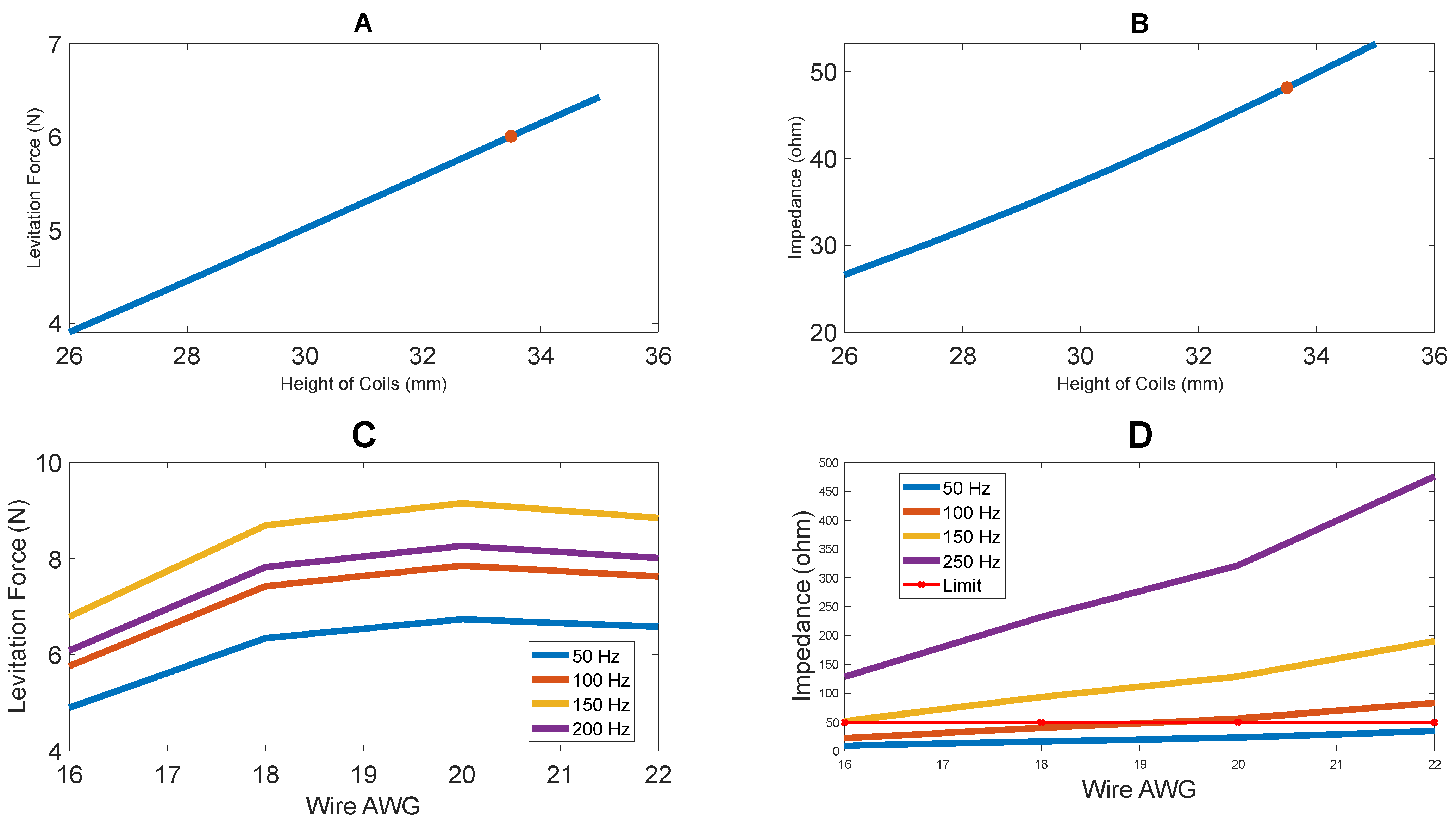
20,21] study the impact of laminated cores on the impedance experienced by the system as a function of frequency. From the results presented, it is evident that laminated cores contribute to increasing the impedance of the system at high frequencies. However, at low frequencies (50 Hz to 1000 Hz), the impact of laminated cores on impedance is minimal.
The development of a feedback controller to facilitate steady state levitation is also an important consideration. Ref. [22] highlights the development of a passive levitation system for transportation applications, which includes no electrical components installed within the carrier. The key emphasis is placed on control of the system using Least Quadratic Regulator (LQR) control. The work was further extended in [23] by placing an emphasis on the design and optimization of the maglev carrier system for transportation purposes. Conrtoller2 highlights the levitation and suspension of a metallic ball using an electromagnetic coil. An IR sensor is used to provide positional feedback and an optimized PID controller is developed to facilitate steady state levitation. Ref. [24] highlights the use of feedforward control within industrial processes. The article highlights two specific approaches to feedforward control: First, the use of feedforward modeling of anticipated/expected disturbances and accounting for these variations within the control system to improve the overall system accuracy and efficiency. Second, the use of estimating the output of the controller using the inverse plant model working in conjunction with the closed-loop control model. Finally, the article highlights the example of a feedforward controller implemented within the plasma etching chamber of a semiconductor manufacturer.
The research presented in this article highlights the successful development of two novel levitation systems with a significant improvement in performance compared to the prototype previously developed by the authors in [17]. The newly developed systems saw a 77% increase in levitation height (from 4.5 mm in [17] to 8 mm in this article), a 476% increase in the surface area for powder deposition activities (from 1963 mm 2 in [17] to 11,309 m2 in this article), and assuming a powder deposition rate of 1 g/min, at least a 346% increase in time available for AM operations (from 15.2 min in [17] to 67 min in this article) by having the ability to support 340% additional mass (from 15.2 g in [17] to 66.74 g in this article) within the limits of allowable inputs. The improvement in the performance of the newly developed levitation systems highlights the significant enhancement for performance with AM operations, therefore highlighting the contributions of this article.
The article also highlights the implementation of a feedback controller to facilitate stable suspension at the desired set point. Two different approaches were undertaken in this article. The first was the development of a PID controller. The PID controller performs quite well, with a rise of 7.52 s, a settling time of 12.56 s, and an overshoot of 1.934 mm for the desired setpoint of 1.468 mm. Finally, a feedforward controller was added in conjunction with the PID controller. The final levitation system has a rise time of 3.68 s, a settling time of 3.9 s, and a 0% overshoot. This marks the first implementation of a feedback controller for a magnetic levitation system with compatibility with AM operations in mind.

2. Theory

2.1. Working Principle

The working principle has been described in our previous work [16,17]. It is discussed here as well. The analytical models were studied through [25].
First, Ampere’s law stated that time-varying currents in a current-carrying conductor will produce magnetic fields that are variable with time. The magnetic fields will have axial (z-axis) and radial (x, y-axis) components. This is given by Equation (1).
B · d l = J · d A
where B is the magnetic field generated, l is the length of the current-carrying conductor under consideration, J is the current density, and A is the conductor’s cross-sectional area. Next, according to Faraday’s law, time-varying magnetic fields generate an electric potential (and subsequent current flow known as eddy currents) in a conductor within the magnetic field’s sphere of influence. This is given analytically by (2).
1 σ J . d l = d d t B . d A
where σ is the conductivity of the levitated geometry material, J is the induced current in accordance with Faraday’s law and B is the time-varying magnetic field. Finally, Lorentz’s law states that the induced currents interact with the source magnetic field to produce the forces in the axial and radial axes to facilitate stable suspension. This is given by the Equation (3).
F = J × B

2.2. Levitation System Description

The overall structure of the levitation system remains unchanged from the first iteration of the prototype developed [17]. The levitation system is made up of two current-carrying coils that carry current in opposite directions. The lift force in the z-axis is provided by the inner coil to allow levitation over the coils. The outer coil is in charge of producing forces in the XY plane in order to keep the disc at the desired equilibrium point.
To facilitate magnetic focusing, the coils are embedded within a highly magnetized core material. Two different alternative cores are considered—a laminated core system and a solid core system. As explained in more detail in Section 4, a laminated core is comprised of thin sheets made of high-permeability material. These sheets have a layer of insulation to ensure that minimal eddy currents are produced within the core. This results in reduced losses due to eddy current production within the core. However, due to the gaps within the laminated core geometry, there is a decline in the performance of the system. A solid core, on the other hand, is comprised of a solid geometry made of a high-permeability material. This results in higher losses due to eddy current. However, the overall performance of the system is expected to be better due to no gaps within the core.

2.3. Electro Magnetic (EM) Coils as RLC Circuit

As explained in [17], the impedance of the EM Coils, which is the overall resistance offered by the levitation system is a combination of its DC resistance, inductive reactance, and capacitive reactance is given by the Equation (4).
Z = R D C 2 ( X L X C ) 2
where X L is the inductive reactance, X C is the capacitive reactance, R D C is the DC resistance and Z is the impedance of the levitation system. The inductive and capacitive reactance is given by Equation (5).
X L = 2 π f L , X C = 1 2 π f C
where L is the inductance of the coils, C is the system’s parasitic capacitance, and f is the frequency on input.

2.4. Analytical Modelling of RLC Circuit

Figure 1 represents the RLC circuit modeling of the levitation system. The levitation system is made up of two coils. Each coil can be treated as an inductor with some internal resistance. The interaction of the magnetic field between the two coils also results in the induction of mutual inductance between the two coils.
Using Kirchhoff’s voltage loop rule, the circuit can be represented in Equation (6).
V 1 + I . R 1 + j . ω . L 1 . I j . ω . L 12 . I j . ω . L 21 . I + j . ω . L 2 . I + I . R 2 = 0
Here, R 1 is the internal resistance of the inner coil (coil 1), R 2 is the internal resistance of the outer coil (coil 2), L 1 is the self-inductance of coil 1, L 2 is the self-inductance of coil 2, L 12 and L 21 is the mutual inductance between the two coils, ω is the angular frequency 2 . π . Frequency), j is the imaginary unit.
The coil characteristics can be measured and the Equation (6) can be solved to determine the current through the coil for given voltage input. Since ANSYS Maxwell calculates the input current from the voltage definition, using the analytical model is an excellent strategy to double-check whether the simulation inputs defined are correct.

3. Need for New Systems

A working prototype of the levitation system capable of supporting AM operations has been developed, as highlighted in [17]. The performance and compatibility with AM applications of the prototype were verified from a preliminary perspective.
Despite producing satisfactory performance and results, it was discovered that there were several avenues of improvement of performance. First, as established in [17], because they carry current in opposite directions, the inner and outer coil strengths (product of the number of turns times current through the coils) are in conflict. The strength of the outer coil was much higher, which resulted in high restoration forces in the lateral axes, however, not sufficient levitation forces in the axial axis. In order to reduce the strength of the outer coil, a resistor was added in parallel to drive the current away from the outer coil. This resulted in a significant current (2.9 A RMS) passing through the resistor and significant power (261.22 W) that is dissipated within resistors. This can be seen as wasted power, therefore reducing the efficiency of the system. As highlighted in Table 1, the prototypes developed in this article do not require any adjustments to the strength of coils. Thus, there is no current supplied to a resistor in parallel to the outer coil, therefore, resulting in no wasted energy.
In addition, the first prototype was also only capable of levitating a disc with a radius of 25 mm. Thus, the surface area available for AM operations was also relatively low. Furthermore, the first prototype was only capable of supporting the weight of the levitated disc and 15.2 g of added mass. Assuming a mass flow rate of 1 g/min [26], the available time for material deposition is restricted to 15.2 min. This would result in significant limitations in geometry that can be built using this method.
Finally, the levitation height, which is the steady state position of the disc as a function of time, is limited to 4.5 mm. There is significant potential to improve the system’s performance.
These avenues for improvements have been highlighted in Table 1. The development of 2 distinct levitation systems has been outlined in this article. However, the final performance improvements have also been highlighted in Table 1. As it can be seen, the new systems are capable of producing much better results.

4. Laminated Core Levitation System

Laminated cores are comprised of sheets coated with insulated materials stacked together to form the core. Laminated cores are used to prevent the induction of eddy currents within the core, therefore minimizing the losses occurring due to the induced eddy currents.

4.1. Optimization

Laminated sheets are usually available in pre-defined dimensions. It is possible to cut custom-sized sheets to build the core. However, the process of cutting hundreds of sheets to a custom size would be too time-consuming, and existing lamination sheet sizes can also produce satisfactory system performance. Thus, in order to facilitate fast fabrication, pre-defined lamination sheets are used for the research. A thin film on the laminated sheets prevents conductor-to-conductor contact. This results in insignificant eddy current induction within the core and subsequently results in reduced core losses. The laminated sheets are held together with the addition of epoxy.

4.1.1. Selection of Lamination Sheet Size

Three different options of lamination sheet sizes were obtained from a local manufacturer’s catalog and have been presented in Figure 2. Figure 2A highlights the pertinent variables differentiating the options and Figure 2B highlights the variations of the parameters for all options. Only the E-stamped sheets were required for the application. These laminated sheets were then subjected to simulation analyses using ANSYS Maxwell. It should be noted that all these laminated sheets were stacked around the z-axis. A central hole of 23 mm was added to all alternatives to maintain consistency. 18 AWG (with a current carrying capacity of 5 A) was used within all lamination core systems. The levitation force on a disc of 60 mm radius and 5 mm height made of aluminum and placed 2 mm above the levitation system was studied and plotted. The input supplied to the system is 5 A at 60 Hz. A stacking factor, which is the ratio of the volume of lamination sheets within the assembly to the total volume available, of 0.7 was considered and a fill factor, which is the area of copper wires in coils to the total area available, of 0.7 was considered for the simulations.
Sizes of lamination sheets smaller than these alternatives produced very low levitation forces, with forces <1 N for 1 mm levitation height which is lower than the weight of the disc (1.49 N). Sizes higher than these produced a very high impedance (over 60 ohms), therefore losing the ability to provide a 5 A current input to the coils with a 300 V voltage input.
Figure 3 highlights the output specifications of the laminated core system. The number of turns, calculated based on the methodology presented in Appendix A, has been presented in Figure 3A. As expected, alternative 2 has the highest number of turns for both the inner and outer coil. However, as highlighted in Figure 3B,C, the output inductance and impedance of the alternative 3 are the highest as well. Most notable, however, the levitation force of alternative 2 is the highest, as highlighted in Figure 3D. With all parameters considered, alternative 2 was pursued in this application.

4.1.2. Wire AWG Selection

For the initial phase, the wire AWG was selected arbitrarily as 18 AWG but applied to all alternatives to maintain consistency. However, several important considerations such as the number of turns of coils, the strength of coils, which is the product of the difference in the number of turns of the outer and inner coils to the current through the coils, inductance, impedance, and levitation force are contingent on the wire AWG. Thus, a deeper analysis was conducted for the wire AWG selection using ANSYS Maxwell. For the analysis, 16–20 AWG wires were considered.
Figure 4A highlights the number of turns of the inner and outer coils for the various wire sizes. It should be noted that the fill factor used for the analysis was 0.7. The current carrying capacity of these wire AWG alternatives is presented in Figure 4B. The maximum current was capped at 10 A, based on the maximum current output of the hardware used. With the development of the number of turns and maximum current carrying capacity, the strength of the two coils was calculated and presented in Figure 4C. As can be seen, the use of 20 AWG produces the best strength of coils. The performance of the different wires was also studied in ANSYS Maxwell. While 20 AWG wire has the highest impedance, as shown in Figure 4D, the impedance is still low enough to facilitate the supply of 5 A with 300 V input. The levitation force produced with 20 AWG wire was also the highest. Thus, 20 AWG was pursued this application.

4.2. Experiment with Laminated Core Levitation System

4.2.1. Simulation vs. Experiment Comparison

For the comparison of simulation data when compared to experimental data, two different approaches were taken. First, the current measured through simulations, analytical modeling, and experiments was compared. Since input current determines other relevant factors such as a magnetic field, levitation force, etc., it was deemed best to compare the performance of the simulation using the same. For the analysis, the coils were connected in series and carrying current in the opposite direction.
The specifications of the levitation system were also subjected to the analytical model developed in Section 2.4. The self-inductance of the inner coil ( L 1 ), the outer coil ( L 2 ), and the total inductance of the two coils in series and oriented to carry current in the opposite direction ( L t o t ) were measured using a Keysight U1732B LCR meter. The measured values are:
  • L 1 = 0.05286 H, L 2 = 0.08549 H, L t o t = 0.1229 H;
  • R 1 = 2.115 Ω , R 2 = 3.372 Ω .
As shown in Figure 5A, the simulation data, the analytical model data, and the experimental data are in close agreement, with a maximum error of 3.84%. This error can be attributed to meshing errors associated with simulation using FEA. This verifies the validity of the simulation data studied so far.
The second approach was to compare the steady state position of the levitated disc obtained experimentally to the steady state position obtained through simulation. Figure 5B highlights the steady state position with a 5 A at 50 Hz input observed experimentally. BK9832B power supply has been used to supply the AC current to the levitation coils. The position of the disc is observed to be 7 mm above the levitation system. The simulation data highlighting the variation of the position of the disc as a function of time, as presented in Figure 5C, is in close agreement with the experimental data.

4.2.2. Levitation Experiment

The experiment was also repeated with 60 mm radius and 4 mm and 6 mm height at 75 Hz and 90 Hz. Figure 6 highlights the results of these levitation experiments. Figure 6A,B highlights the levitation experiment at 75 Hz and Figure 6C,D highlight the levitation experiment at 90 Hz. Thus, the ability of the laminated core levitation system to stably suspend a disc has been clearly established.

4.3. Compatibility with Additive Manufacturing Experiment

The primary objective of this experimental apparatus is to support AM operations. To test the feasibility of the same, it was critical to highlight and test certain performance criteria. This includes the system’s ability to support additional payload and the lateral and axial stability following powder deposition.

4.3.1. Suspension of Additional Payload

As explained in [17], a critical objective of the levitation system is to support additional mass as a function of time. This is because of the mass added due to powder deposition to build geometries using AM. Thus, it is integral for the levitation system to support additional mass as time goes on. Figure 7B highlights the system’s ability to support an additional payload of 15.2 g during levitation. Figure 7C highlights the addition of a 66.74 g mass on the levitated disc.

4.3.2. Impact of Powder Deposition

The impact of powder deposition is another crucial phenomenon that needs to be verified to ensure the satisfactory performance of the levitation system. Assuming a mass flow rate of 1 g/min [26], the velocity of powder of 2 m/s [27] and a nozzle angle of 60-degree [26], the calculator impact force of powder deposition as a worst-case scenario analysis was found to be 0.01 N in [17] within the axial axis. Adding this as an additional force in the negative axial axis, the levitation force and levitation position are studied as a function of time using the transient mode of ANSYS Maxwell.
The resulting levitation force vs. time and position of disc vs. time plots obtained from ANSYS Maxwell has been presented in Figure 8A,B, respectively. As can be seen, the levitation height reduces from 9.1 mm to 8.97 mm, which is a 1.3% reduction in levitation height. Thus, the incorporation of the powder deposition force does not significantly impact the overall stability of the levitated disc. Thus, the compatibility of the levitation system has been highlighted effectively.

5. Solid Core Levitation System

Following the development and successful implementation of the laminated core system, it was also deemed relevant to develop a levitation system comprised of a solid core system. The use of a solid core offers significantly more flexibility with the optimization of dimensions, resulting in a potential improvement of the system. This is because the laminated core sheets were selected from preexisting and pre-cut lamination sheets to facilitate cheaper and faster fabrications. However, the solid core system would offer significantly more control over design variables, offering avenues for improved performance.

5.1. Optimization of the System

For the optimization of the solid core, the direct substitution method was employed. This optimization strategy has been employed for the development of the first iteration of the levitation system developed by the authors [17]. For the optimization, the selected dimensions of the laminated core system were taken as the initial parameters. The dimensions of the coils are subjected to the optimization process. The initial parameters have been listed in Table 2. The critical constraint placed on the system was that the impedance should not exceed 60 ohms, to ensure a 5 A current input with a 300 V input at 50 Hz.

5.1.1. Optimization of Coil Widths

Figure 9A,B highlights the variation of levitation force and impedance as a function of the width of the inner coil (coil 1) and outer coil (coil 2), respectively. It should be noted that the number of turns for both coils is adjusted in accordance with the dimension. For dimensions of coil width greater than 14 mm, the impedance of the system is higher than 60 ohms, resulting in the input current being lower than 5 A, which is the current carrying capacity of 18 AWG wire. As it can be seen, the width of both the inner coil and outer coil produces the highest levitation force and an acceptable impedance is obtained at a width of 14 mm.

5.1.2. Optimization of Radial Placement of Coils

Figure 9C,D highlights the variation of levitation force and impedance of the system as a function of the inner radius of the coils, respectively. With the coil width determined, the determination of the inner radius of the coils determines the radius placement of the coils. The optimized radial placement results in the inner radius of coil 1 as 31 mm and the inner radius of coil 2 as 67 mm, as highlighted in Figure 9C,D.

5.1.3. Optimization of Height of Coils

The height of the levitation system has been varied and the resulting levitation force (Figure 10A) and impedance (Figure 10B) has been obtained. It should be noted that the number of turns for both coils is adjusted in accordance with the dimension. As it can be seen in Figure 10B, for coil heights greater than 33.5 mm, the impedance of the system is higher than 50 ohms. Thus, the ideal height was taken to be 33.5 mm and was pursued.

5.1.4. Wire AWG Selection

Figure 10C,D highlights the variation of levitation force and impedance, respectively, for different wire diameters. Previously, the analysis was restricted to low-frequency inputs. However, the analysis was extended to higher frequency inputs as well. When restricted to relatively low frequencies such as 50 Hz, the use of 20 AWG wires would be feasible, as highlighted previously. However, as shown in Figure 10C, there is a significant increase in levitation force for all wire diameters. However, the impedance goes above the 60-ohm resistance limit for all wire AWG except 16 AWG. Thus, for the solid core system, 16 AWG wire was selected.

5.2. Experiment with Levitation System

5.2.1. Simulation vs. Experimental Data Comparison

As explained in Section 4.2.1, measurement of current has been used to compare the data obtained from simulation, analytical modeling, and experiment.
As conducted previously in the laminated core system, the specifications of the levitation system were also subjected to the analytical model developed in Section 2.4. The measured coil parameters are:
  • L 1 = 0.005 H, L 2 = 0.0084 H, L t o t = 0.0956 H;
  • R 1 = 0.65 Ω , R 2 = 1.14 Ω .
As it can be seen in Figure 11A, the current measurement using simulation analyses, analytical modeling, and experiment are in close agreement with each other, with a maximum error of less than 10%. Thus, the validity of the simulation data has been verified.
Further verification of the simulation data was conducted through the comparison of the steady state position of the levitated disc measured experimentally and using the transient mode of ANSYS Maxwell, which is a mode of simulation that provides a variation of parameters as a function of time. Figure 11B,C highlights the steady state position observed experimentally (Figure 11B) and using the transient mode of ANSYS Maxwell (Figure 11C). As can be seen, the simulation data are in close agreement with the experimental data.

5.2.2. Levitation Experiment

The levitation experiment was conducted with a 60 mm radius disc and 4 mm and 6 mm height, respectively. The experiment was run at 150 Hz and 250 Hz. The results of the experiment have been presented in Figure 12.

5.3. Compatibility with Additive Manufacturing Operations

As previously stated, the primary goal of the system developed through this research is to facilitate AM operations by utilizing the principles of magnetic levitation and suspension. As with the laminated core system, the compatibility of the solid core system with AM applications is tested.

5.3.1. Levitation with Additional Payload

Figure 13 highlights the ability of the solid core system to support added payload as a function of time. This experiment highlights the solid core system’s ability to handle/cope with payload variation as a function of time. This variation occurs primarily due to the mass deposition activities encountered within the AM environment.
With the ability to support 66.74 g of aluminum in addition to the levitated disc with minimal loss of functionality and performance, it has been clearly highlighted that the solid core system can sustain additional payloads as a function of time.

5.3.2. Stability within the Lateral Axes

Figure 14 highlights the solid core systems stability within the lateral axes. As can be seen, in timestep 1, the disc has been provided a large displacement (about 30 mm) on the x-axis. However, timestep 2-timestep 4 highlight the system’s ability to bring the levitated disc back to the center with only the forces imposed on the disc from the levitation system. Thus, it has been highlighted that the system will retain its stability within the lateral axis.

5.3.3. Impact of Powder Deposition

As stated in Section 4.3.2, the impact force of powder deposition of 0.01 N was fed in ANSYS Maxwell, and the stability of the levitation system was studied using ANSYS Maxwell.
Figure 15A highlights the levitation force as a function of time. The levitation force is much higher than the impact force of powder deposition. Thus, it is safe to assume the retention of stability despite powder deposition. Figure 15B highlights the position of the disc as a function of time. As noted, the levitation height at a steady state was very similar despite the introduction of powder deposition force. Thus, the performance of the levitation system has been verified.

6. The Need for a Feedback Controller

The following analysis is only conducted for the solid core system. Since the working principles and factors affecting performance are similar for both systems, the conclusions of this analysis can be extended to the laminated core system as well.
Figure 16 highlights the eddy currents produced with the identical input (100 V RMS at 50 Hz) with only the disc and the disc with the added payload. The added payload is an aluminum disc of 45 mm radius and 4 mm height with a total mass of 67 g. The initial disc is 60 mm in radius and 6 mm in height with a total mass of 121 g. The added payload is conductive; therefore, there is an increase in volume within which eddy currents are produced. At 50 Hz, the skin depth, i.e., the characteristic length within which eddy currents are produced, is 11.6 mm [28]. The sum of the height of the added payload and the initial disc is less than the skin depth. Therefore, significantly more eddy currents are produced with the added payload.
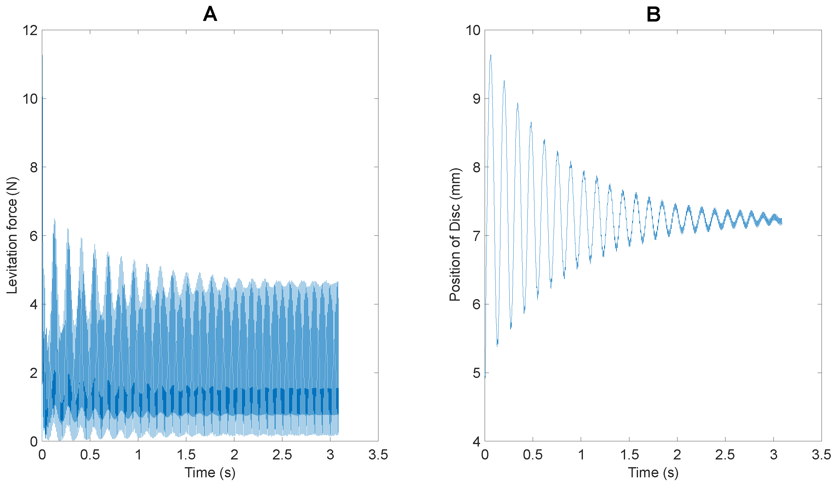
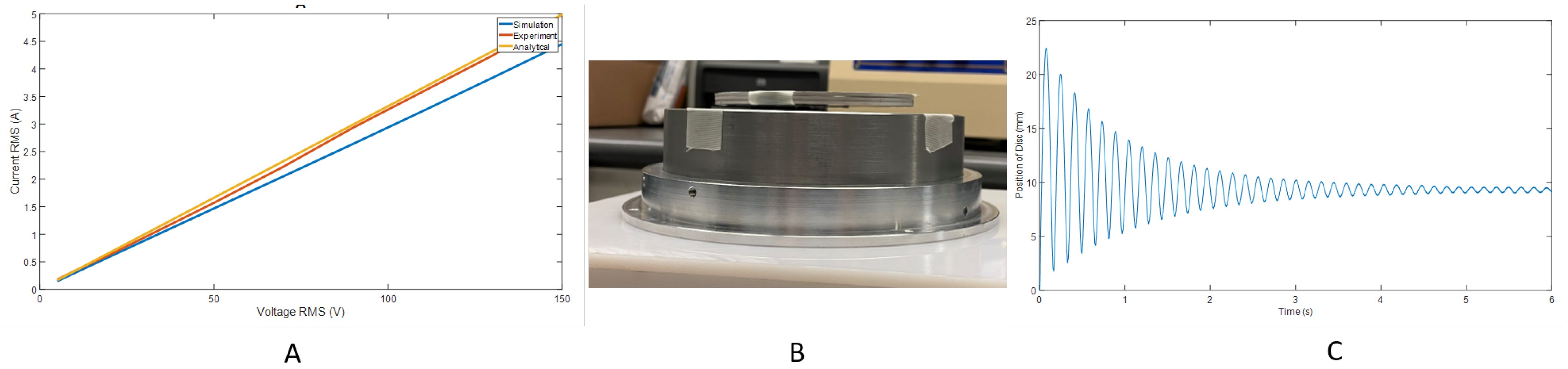
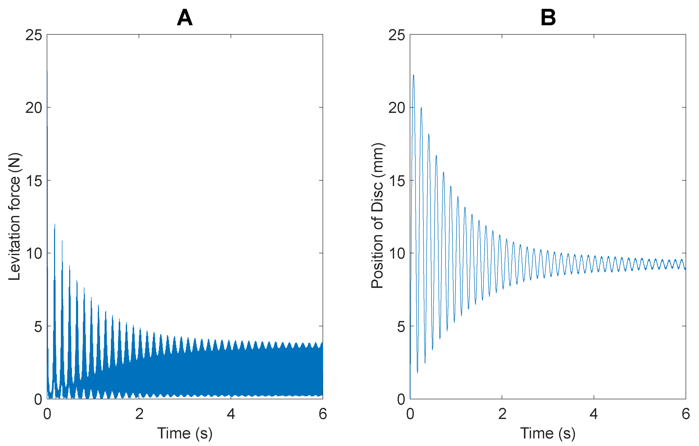
This would explain why the addition of 45% of the initial mass, results in a reduction of 13% reduction in levitation height (From 9.1 mm to 7.85 mm). These data were obtained using the transient mode of ANSYS Maxwell, the performance of which has been verified previously. The resulting comparison of levitation force and position of the disc for the two scenarios has been presented in Figure 17. As can be seen in Figure 17A, there is an increase in levitation force with the addition of the aluminum payload, confirming the claim presented previously.
Within the scope of realistic AM operations, the added mass is going to be much more gradual. With a powder deposition rate of 1 g/min, the calculated powder deposition force of 0.01 N has been incorporated. The comparison of the levitation of only the disc and the disc with powder deposition activities is presented in Figure 17C,D. Again, the data were obtained from ANSYS Maxwell. From the study of the position of the disc vs. time, it can be noted that there is only a decrease of 0.13 mm (1.4%) after 6 seconds of continuous operation. However, complete positional stability is a critical consideration for incorporated LDED-PF AM operations. Thus, the inclusion of a feedback controller to adjust the input current to maintain consistent and stable suspension of the levitated disc is critical to the anticipated implementation of the system.

7. Design of a PID Controller for the Levitation System

The feedback controller mechanism chosen is the proportional-integral-derivative (PID) controller. A PID controller is a feedback-based control loop that is frequently employed in industrial control systems and a wide range of other applications that call for continuously modulated control. When the desired setpoint (SP) and a measured process variable (PV) diverge, a PID controller constantly calculates an error value and makes a correction based on proportional, integral, and derivative terms (denoted P, I, and D, respectively). This type of feedback controller is incorporated within the levitation system to improve the system’s characteristics.
The PID control approach is chosen for this application owing to its simplicity in implementation, the widescale adoption of the control strategy in magnetic levitation applications [29,30,31] and the satisfactory performance produced by the controller, as highlighted in subsequent sections. The proposed controller is first analyzed in MATLAB/Simulink. The optimal gains for the controllers were obtained using the in-built Simulink PID tuner. Subsequently, the controller is implemented within the hardware infrastructure. Through experimental trial and error, the performance of the tuned parameters obtained from Simulink tuner were verified. The controller implementation has been restricted to the laboratory setting.

7.1. Closed Loop Controller Using Position Feedback—Simulation

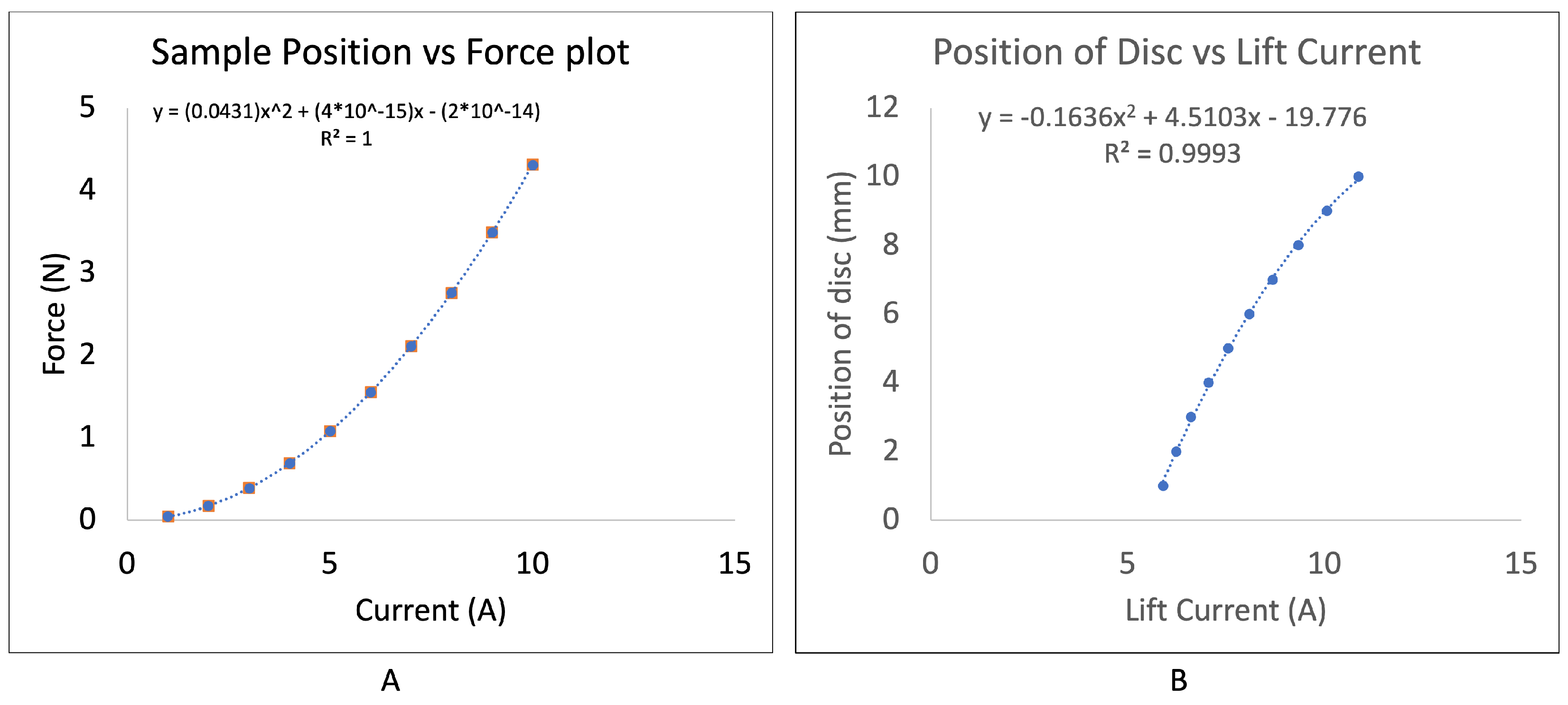
For the position feedback controller, a relationship between the input current and the output force was developed using the principle of curve fitting, keeping the position of the disc constant. The developed relationship was then used to calculate the lift current, i.e., the minimum RMS current required to stably levitate the disc at a given position [16]. The lift current was calculated for positions from 1–10 mm above the levitator, with a sample plot shown in Figure 18A. Again, using the principle of curve fitting, a relationship between the position of the disc and the lift current previously calculated was developed. Thus, the governing equation relating the relevant output (position of the disc above the levitation system) and the pertinent input (input current to coil to stably levitate the disc at a given position) was developed, as shown in Figure 18B.
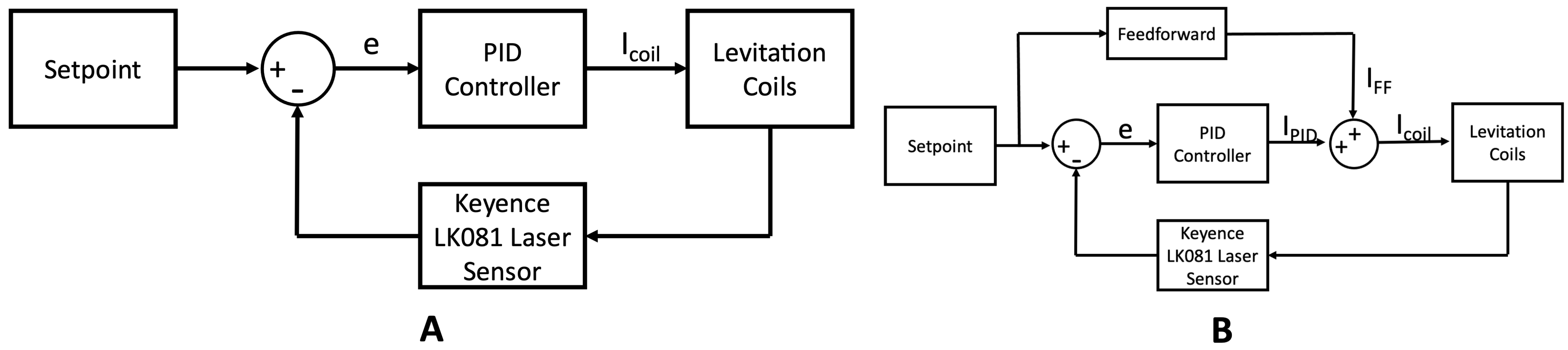
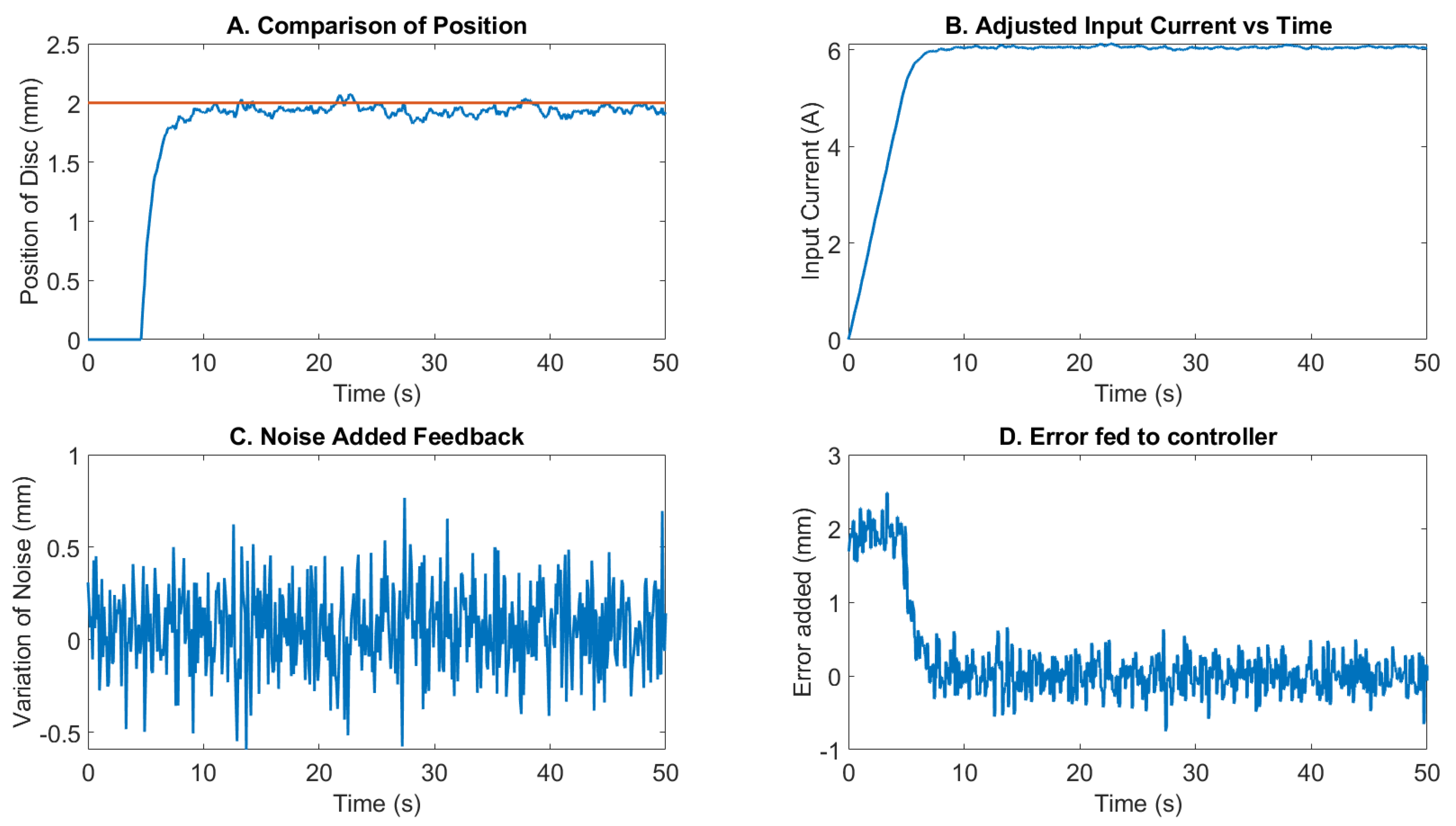
A simple 1-D PID controller was developed using Simulink. The Simulink model highlights the operation of the controller with each output parameter presented as well. The Gaussian noise with a mean of 0.05 and variance of 0.05 was added to mimic noise encountered with sensor feedback. The overall controller diagram has been highlighted in Figure 19A.
The controller is developed at 120 Hz frequency input. The set point, i.e., the desired position of the disc, was set at 2 mm above the levitation system. The critical controller parameters were obtained using the inbuilt Simulink PID tuning. The tuned parameters were K p = 0 , K d = 0 and K i = 0.5 . The Gaussian noise added to mimic sensor feedback noise has been highlighted in Figure 20C, resulting in the error fed to the PID controller, as shown in Figure 20D.
The key controller performance parameters from the simulation results are calculated from the data presented in Figure 20A. The rise time (7.33 s), the settling time (9.043 s), the overshoot (0%), and RMS steady state oscillation (53 μm) are the critical controller performance parameters. As it can be seen in Figure 20B, since the input current is 0 at the time t = 0, the controller takes significantly longer to grow to achieve the steady state position.

7.2. Incorporation of a Feedforward Controller—Simulation

The large rise time and settling time of the controller are a result of the tuned PID controller being purely integral. This results in the controller requiring significant time to grow the input current from 0 to the desired output. However, through the incorporation of a feedforward forward, this performance can be improved significantly, as highlighted in Figure 19B.
The first critical step in the analysis of the feedforward controller is to estimate the desired output to achieve the relevant setpoint. The output estimation is conducted by modeling the plant and using the model’s inverse to determine the output. However, the output is not going to be perfect. To overcome residual error, the feedback controller will be used in conjunction with the feedforward controller. The updated Simulink model presents the incorporation of a feedforward element estimating the desired input for stable levitation and also accepting the feedback controller’s adjustments to account for any process-based errors.
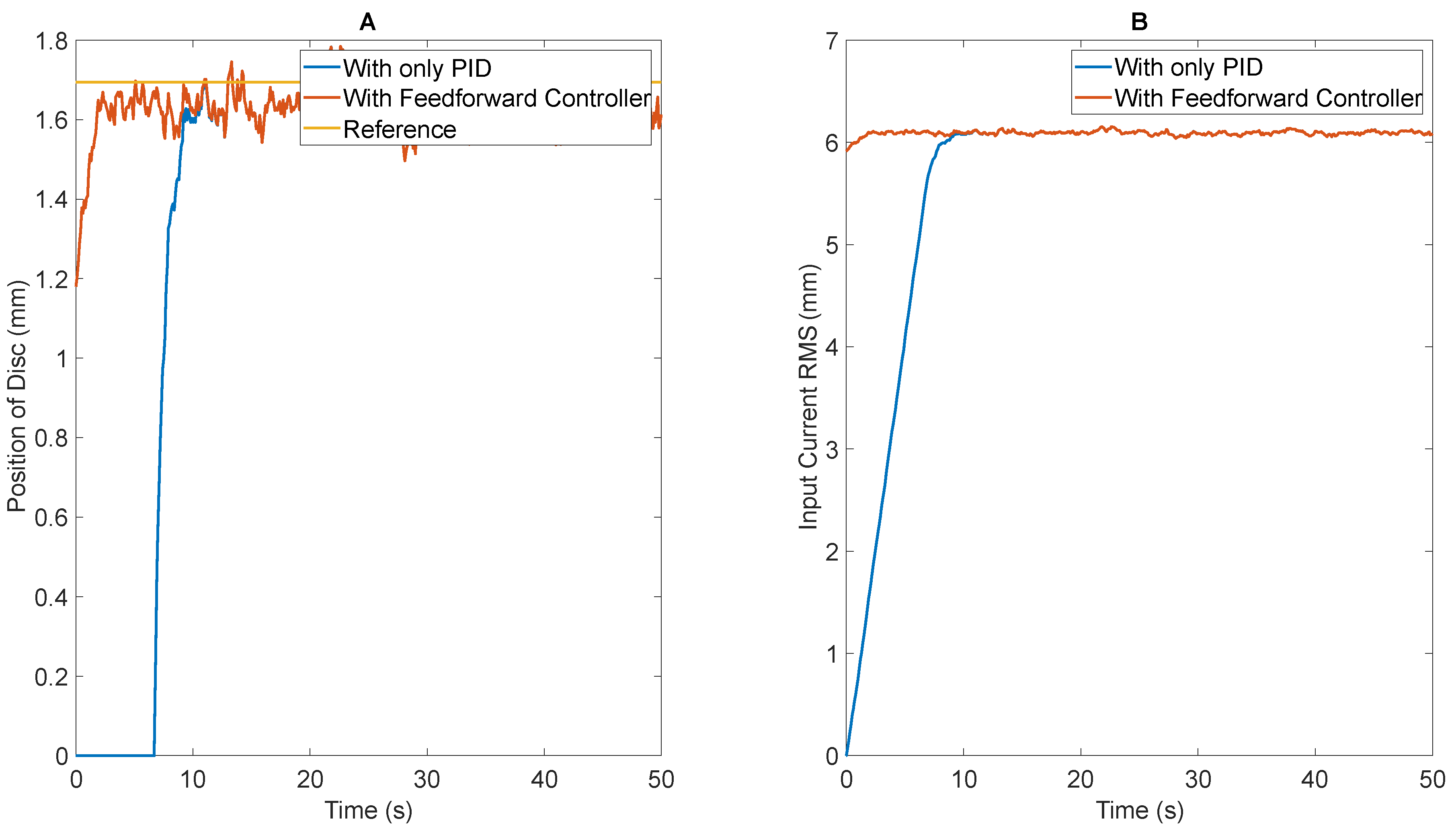
Figure 21A highlights the variation of the position of disc vs. time using the conventional PID controller and the incorporated feedforward controller in conjunction with the controller. The impact of the feedforward controller is more evident in Figure 21B, where the initialization of the input current results in a significant improvement in the performance of the controller.
Quantifiably, there is a 77% reduction in rising time (from 7.33 s to 1.71 s) and a 67% reduction in settling time (from 9.043 s to 3.04 s) with no significant impact on the steady-state RMS error and the overshoot of the system. Thus, the improvements offered by the feedforward levitation system have been highlighted through the simulation environment.

7.3. Closed Loop Controller Using Position Feedback—Experiment

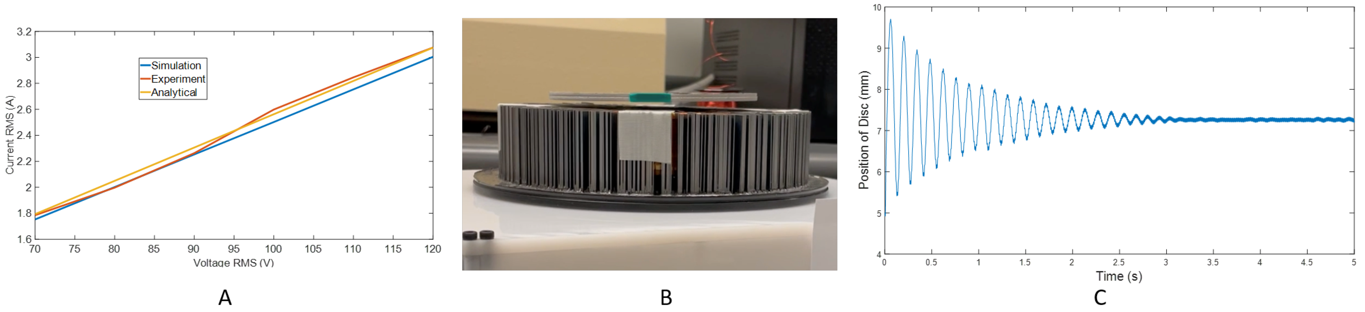
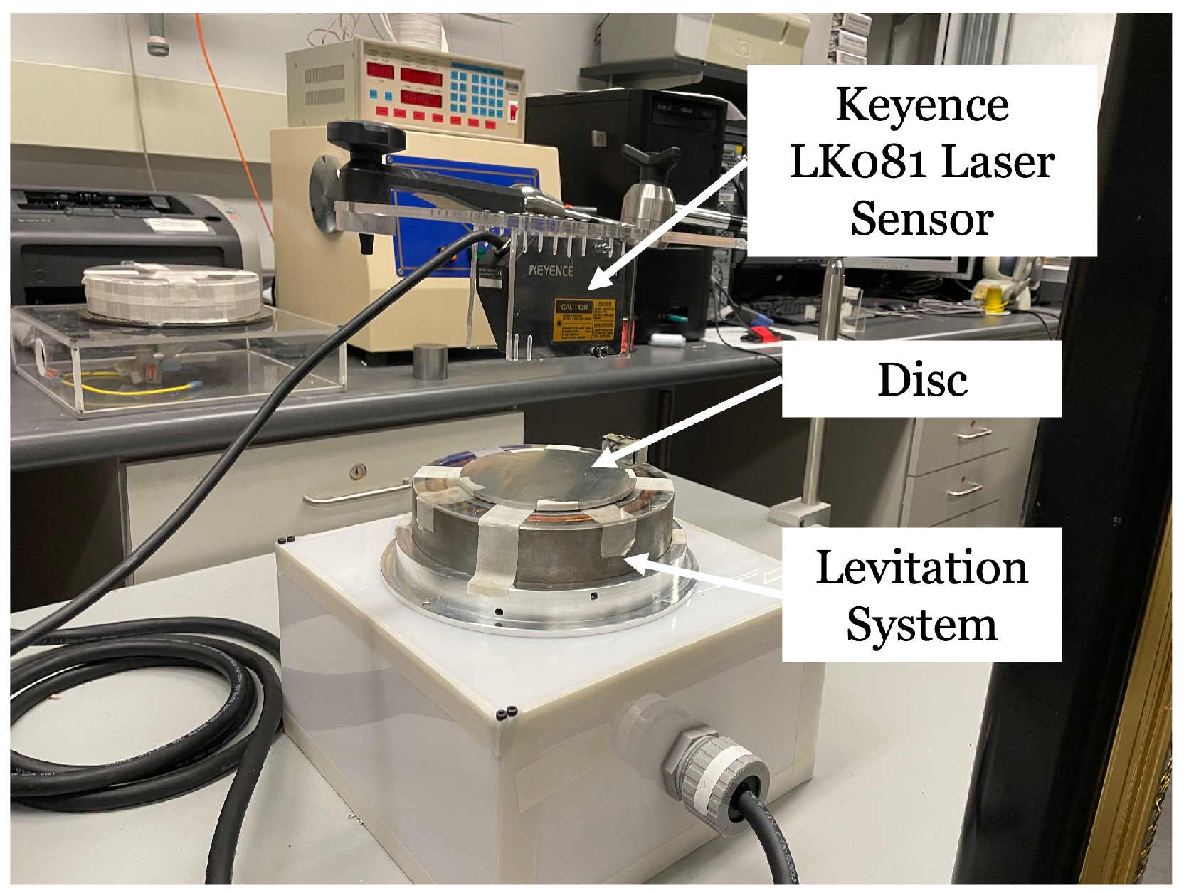
The tuned PID controller is implemented experimentally. The controller is implemented within the laboratory setting. The experimental apparatus has been shown in Figure 22. The laser sensor used for the analysis is the Keyence LK 081 with an analog output resolution of 3 μm/mV and a sampling frequency of 976 Hz. The power supply utilized is the same BK Precision 9832B presented previously. The power supply accepts analog input to adjust the output voltage for improved controllability of the system. A simple Arduino Uno controller is used for the analysis. The Arduino Uno reads the analog input, processes it, and updates the input to the power supply at a frequency of 125 Hz.
The estimation of the desired input current to coils is computed through modeling the output of the Arduino Uno (controller) to the input current to the coils (actuator) experimentally using the principle of curve fitting. The relationship developed is utilized for the estimation of the input current.
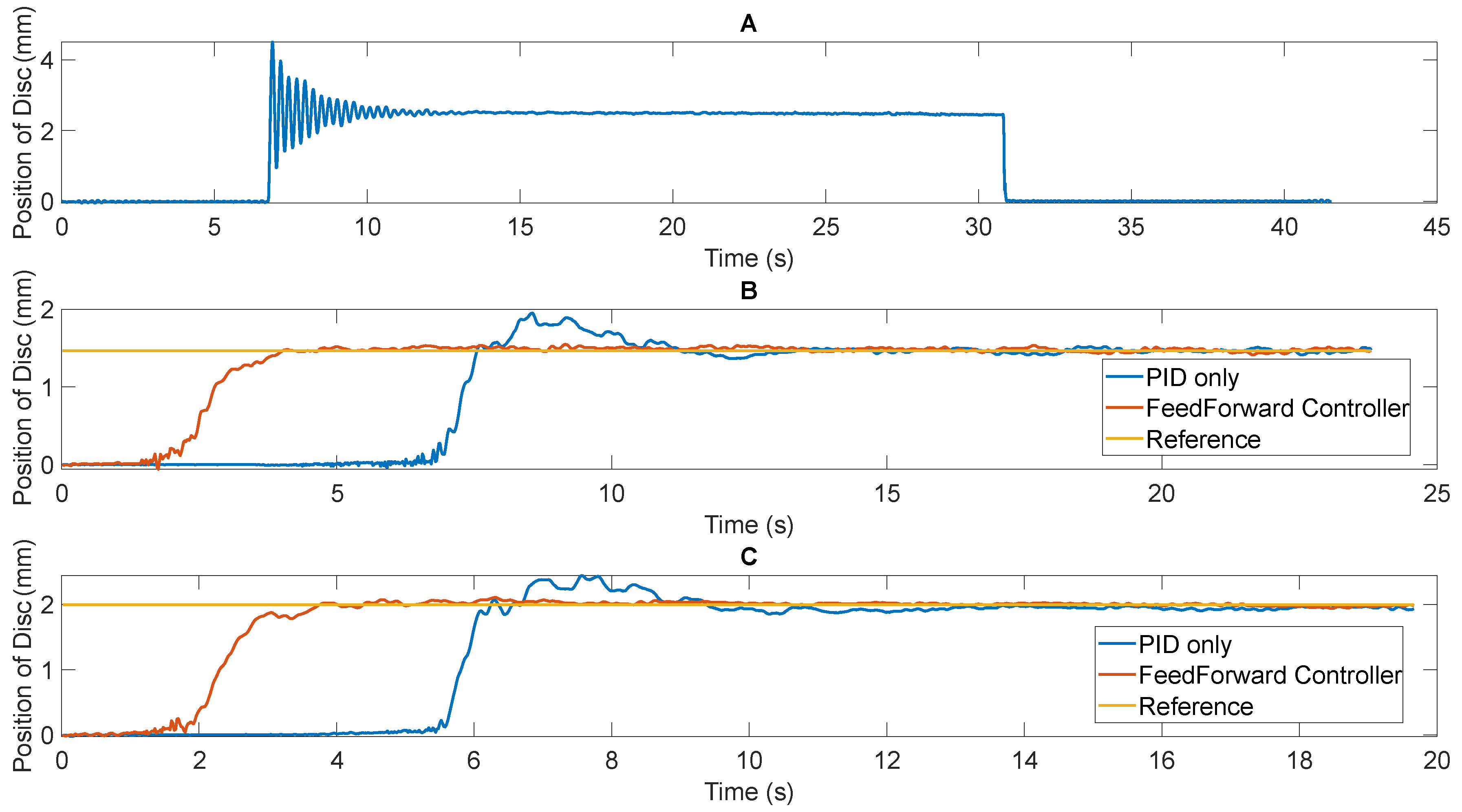
Figure 23A highlights the variation of the position of disc vs. time with no closed loop controller. As can be seen, the steady state value is 2.5 mm above the levitator, with a maximum overshoot of 4.97 mm (198.8% of steady state value) and a settling time of about 4.1625 s. At a steady state, the maximum amplitude of the oscillation measured is 25 μm.
Figure 23B,C highlights the variation of the position of the disc vs. time with a tuned PID controller (shown in blue). The PID controller parameters are the tuned parameters obtained using the Simulink inbuilt tuner (Kp = 0, Ki = 0.5, Kd = 0). Two distinct setpoints were studied—1.468 mm (Figure 23B) and 2 mm (Figure 23C). Figure 23B,C also highlights the incorporation of the feedforward controller (highlighted in orange). The comparison of the performance of the PID controller with and without the feedforward controller is shown in Table 3. Due to the low integral gain for the PID controller, the changes to the input current is slow based on the feedback from the laser sensor. This results in high rise time, settling time, and overshoot errors. However, at steady state, the controller maintains desired set point position satisfactorily. Through initialization of the current to a non-zero initial value, the slow growth of the current serves as an asset to eliminate overshoot errors and significantly reduce rising time and settling time of the controller.
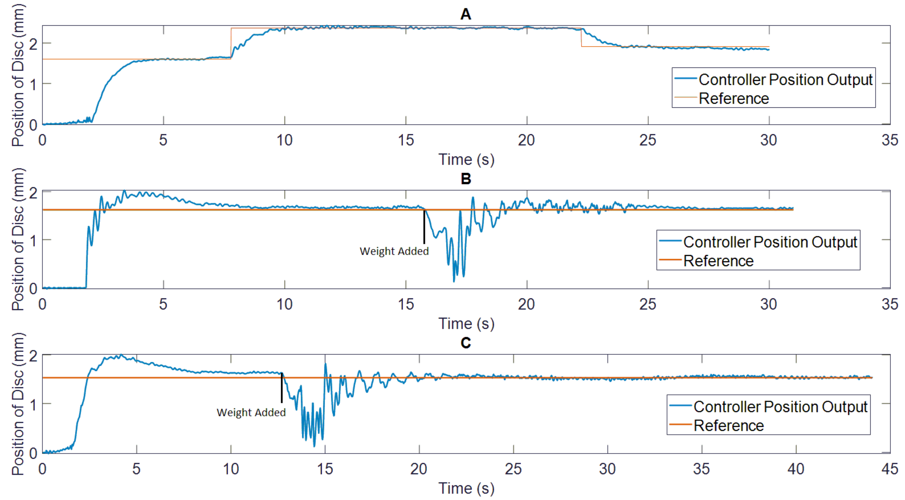
Next, the ability of the levitation control system to adjust the height of the levitation was tested. 
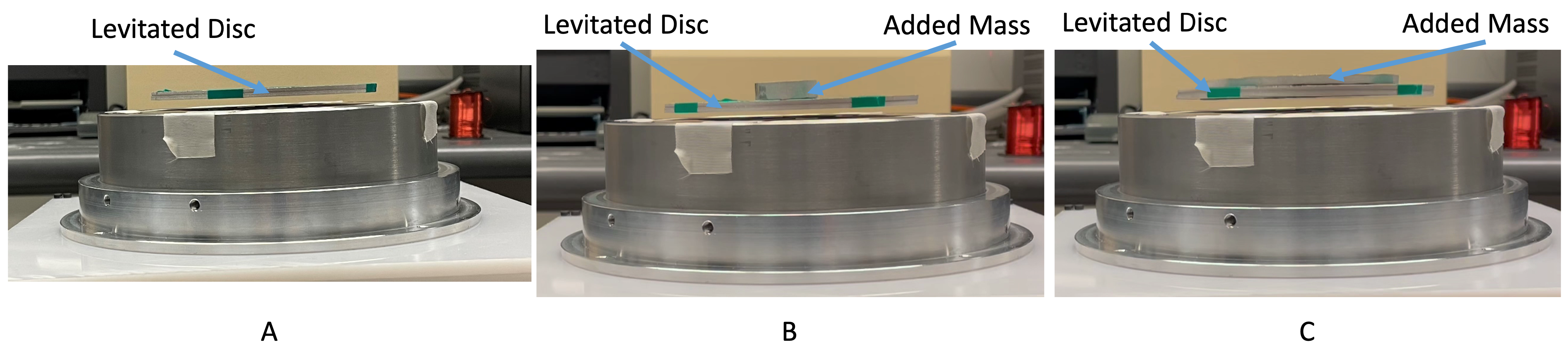
Figure 24A highlights the system performance at multiple heights. For the analysis, the height was first set to 1.6 mm, following which the height was increased to 2.37 mm and finally the height was reduced to 1.9 mm. The system performance is in line with expectations. Next, the performance of the levitated disc to maintain the desired height after the addition of an added payload was tested. First, the levitated disc was allowed to achieve the desired height. Following the achievement of steady-state levitation, a 15.6 g and 26 g aluminum disc was added to the levitated disc. As it can be seen in Figure 24B,C, the levitation system is able to maintain stable levitation with the added payload as well.

8. Conclusions and Future Work

The development of two distinct new levitation systems has been presented in this article. The two systems offer variations in dimension, wire AWG employed for coil development, and the core type.
The first system is developed within a laminated core system. The design decisions to select the optimum system have been presented. The comparison of simulation data is presented with experimental data, with a variation in current measurement restricted to 3.84%. The steady-state levitation position of the disc observed experimentally and through simulation is also in close agreement. The levitation experiment is deemed a success, with levitation height as high as 8 mm offered at 90 Hz. The compatibility of the levitation system with AM operations was also tested. The levitation system also offers the ability to levitate a disc with 66.74 g of added payload, therefore highlighting the system’s ability to cope with added payload as a function of time. The impact force of powder deposition was also tested using simulation analyses. With the addition of the impact force in the negative axial axis, the steady state levitation height reduces by a mere 0.1 mm, therefore highlighting the system’s ability to retain stability despite powder deposition activities.
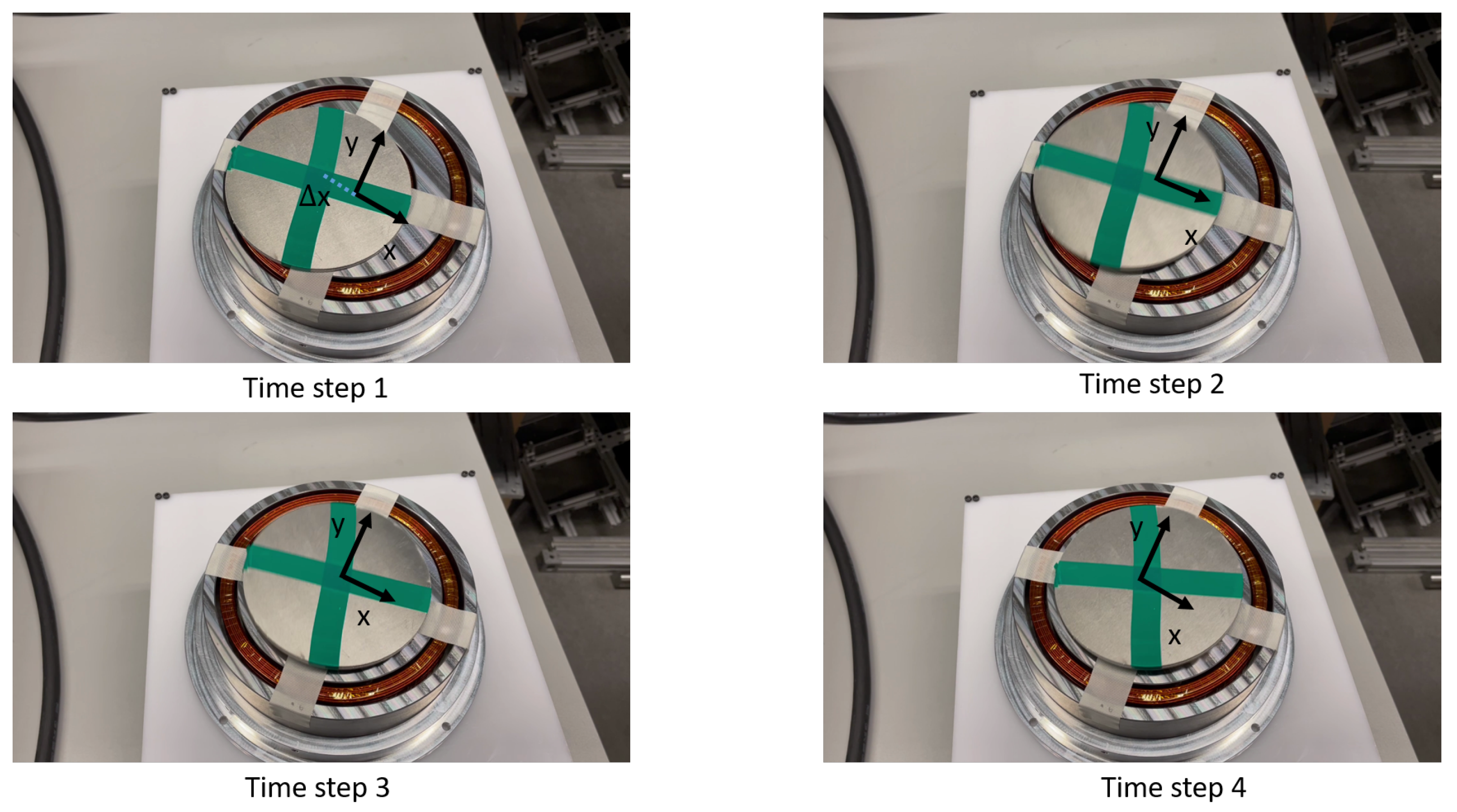
The second system developed is embedded within a solid low-carbon steel system. The optimization and design decisions with the system development have been presented. As in the case with the laminated core system, the simulation and experimental data were compared and observed to be in close agreement, within 10% of one another. The levitation experiment was also successful at multiple frequencies, offering levitation heights as high as 8 mm at 150 Hz. Again, the compatibility of the system was tested with AM operations. First, the system’s ability to cope with added payload as a function of time. The system displayed the ability to support 66.74 g of added mass with no loss in stability. Next, the stability within the lateral axis was also tested. A high initial displacement of 30 mm was provided to the disc. The system displayed the ability to bring the disc back to the equilibrium point with only the non-contact magnetic forces offered by the levitation system. The impact of powder deposition was also tested with the solid core levitation system. The system retained stability and the steady state position was reduced by 0.14 mm with the incorporation of powder deposition forces.
Next, to further improve the performance of the system to maintain stable steady state levitation to support AM applications, a one-dimensional controller was developed to adjust the input current. A conventional PID controller was developed that was able to significantly reduce the overshoot, however, the settling time and rise time of the PID controller were very high. Through the incorporation of a feedforward element to estimate the desired input to work in conjunction with the PID controller, a 51% reduction in rising time, 69% reduction in settling time, 31% reduction in overshoot, and 37% reduction in steady-state RMS error was observed. The system’s ability to support levitation height controllability and the ability to support added mass without losing any levitation height has also been highlighted. The developed controller is only implemented in the laboratory setting.
Through these analyses, two new systems which possess an improved ability to support AM operations have been developed. As outlined in our previous article [17], the critical next step is to test the newly developed levitation systems within the AM environment. The testing of the levitation system is to be conducted within the DMD IC-106, an industrial-scale metal 3D printer. The critical considerations to ensure safe operations are:
  • Development of a set of process parameters to build a new geometry on the levitated disc
  • The levitation system is protected from the AM machine enclosure environment. This includes protection of the coils and associated electronics from the conductive dust, protection from the environment within the AM enclosure, and protection from the heat and thermal stresses offered by the laser during AM operations
  • No collision occurs between the levitation system and the AM machine infrastructure
  • No laser back reflection (LBR) occurs. This is to ensure that the laser is not damaged during the operation
  • Testing the compatibility of the laser sensor presented in this article and other sensors such as cameras and IR sensors within the DMDIC106 machine.
The implementation of the controller mechanism developed is also to be tested within the AM machine. Currently, a laser sensor has been used to provide the feedback input to the controller. However, the powder particles expected within the AM machine will result in significant noise with a laser sensor. This will make the laser sensor output less reliable. In addition, the laser sensor is currently placed above the levitated disc. Its current placement prevents the interaction of the material nozzle and laser and the levitated disc, therefore preventing successful deposition activities. This prevents the use of a laser sensor within the AM machine to facilitate the feedback controller.
The selection of a sensor with higher feasibility within the AM machine and the subsequent implementation within the AM machine are the pertinent next steps. The use of cameras coupled can serve as a viable alternative sensor input, as highlighted by [32,33].
The performance of the feedback controller can be subjected to further improvement. Using other feedback control techniques with precedence with magnetic levitation systems can result in further improvement in performance. This includes techniques such as Linear–Quadratic Regulator (LQR) [34] and Pole Placement Controller (PPC), [35] amongst others.

Author Contributions

Manufacturing, methodology, analysis, investigation, data collection, formal analyses, and preparation of the first draft: P.K. Conceptualization, methodology, supervision, funding acquisition, project administration, review, and editing: M.B.K. All authors have read and agreed to the published version of the manuscript.

Funding

This work was by the umbrella of the Holistic Innovation in Additive Manufacturing (HI-AM) Network through the Natural Sciences and Engineering Research Council of Canada (NSERC) and Canada Foundation for Innovation (CFI).

Institutional Review Board Statement

Not applicable.

Informed Consent Statement

Not applicable.

Data Availability Statement

Data available from the authors upon request.

Conflicts of Interest

The authors declare no conflict of interest.

Appendix A. Methodology to Calculate Number of Turns

The number of turns is calculated from a coil winding perspective, with the fill factor kept in mind. The governing equations are:
N a x i a l = h d w , N r a d i a l = r o r i d w , N t o t a l = N r a d i a l . N a x i a l . η
where h is the height of the coil, r o is the outer radius of the coil, r i is the inner radius of the coil, d w is the wire diameter, and η is the winding efficiency. This approach was used to calculate the number of turns for wire AWG selection.

References

  1. Okress, E.; Wroughton, D.; Comenetz, G.; Brace, P.; Kelly, J. Electromagnetic levitation of solid and molten metals. J. Appl. Phys. 1952, 23, 545–552. [Google Scholar] [CrossRef]
  2. Yamamoto, K.; Oka, K.; Harada, A. Non-contact suspension system by rotation mechanism using multiple permanent magnets. In Proceedings of the 2020 23rd International Conference on Electrical Machines and Systems (ICEMS), Hamamatsu, Japan, 24–27 November 2020; pp. 50–53. [Google Scholar]
  3. Liu, X.; Lu, Y.; Zhang, Q.; Zhang, K. An Application of Eddy Current Effect on the Active Detumble of Uncontrolled Satellite With Tilt Air Gap. IEEE Trans. Magn. 2019, 55, 1–11. [Google Scholar] [CrossRef]
  4. Zhang, X.; Trakarnchaiyo, C.; Zhang, H.; Khamesee, M.B. MagTable: A tabletop system for 6-DOF large range and completely contactless operation using magnetic levitation. Mechatronics 2021, 77, 102600. [Google Scholar] [CrossRef]
  5. Jung, K.S.; Won, K.M. Contactless transfer of conductive rod using an electrodynamic wheel. Int. J. Precis. Eng. Manuf. 2011, 12, 741–744. [Google Scholar] [CrossRef]
  6. Park, J.K.; Kyung, J.H.; Shin, W.C.; Ro, S.K. A magnetically suspended miniature spindle and its application for tool orbit control. Int. J. Precis. Eng. Manuf. 2012, 13, 1601–1607. [Google Scholar] [CrossRef]
  7. Kang, S.; Kim, J.; Pyo, J.B.; Cho, J.H.; Kim, T.S. Design of magnetic force field for trajectory control of levitated diamagnetic graphite. Int. J. Precis. Eng. Manuf.-Green Technol. 2018, 5, 341–347. [Google Scholar] [CrossRef]
  8. Toyserkani, E.; Sarker, D.; Ibhadode, O.O.; Liravi, F.; Russo, P.; Taherkhani, K. Metal Additive Manufacturing; John Wiley & Sons: Hoboken, NJ, USA, 2021. [Google Scholar]
  9. Alimardani, M.; Toyserkani, E.; Huissoon, J.P.; Paul, C.P. On the delamination and crack formation in a thin wall fabricated using laser solid freeform fabrication process: An experimental–numerical investigation. Opt. Lasers Eng. 2009, 47, 1160–1168. [Google Scholar] [CrossRef]
  10. Manoharan, M.; Kumaraguru, S. Path Planning for Direct Energy Deposition with Collaborative Robots: A Review. In Proceedings of the 2018 Conference on Information and Communication Technology (CICT), Jabalpur, India, 26–28 October 2018; pp. 1–6. [Google Scholar]
  11. Rittinghaus, S.K.; Schmelzer, J.; Rackel, M.W.; Hemes, S.; Vogelpoth, A.; Hecht, U.; Weisheit, A. Direct energy deposition of TiAl for hybrid manufacturing and repair of turbine blades. Materials 2020, 13, 4392. [Google Scholar] [CrossRef] [PubMed]
  12. Ryu, D.J.; Ban, H.Y.; Jung, E.Y.; Sonn, C.H.; Hong, D.H.; Ahmad, S.; Gweon, B.; Lim, D.; Wang, J.H. Osteo-compatibility of 3D titanium porous coating applied by direct energy deposition (DED) for a cementless total knee arthroplasty implant: In vitro and in vivo study. J. Clin. Med. 2020, 9, 478. [Google Scholar] [CrossRef] [Green Version]
  13. Barro, Ó.; Arias-González, F.; Lusqui nos, F.; Comesa na, R.; del Val, J.; Riveiro, A.; Badaoui, A.; Gómez-Ba no, F.; Pou, J. Improved commercially pure titanium obtained by laser directed energy deposition for dental prosthetic applications. Metals 2020, 11, 70. [Google Scholar] [CrossRef]
  14. Tepylo, N.; Huang, X.; Patnaik, P.C. Laser-based additive manufacturing technologies for aerospace applications. Adv. Eng. Mater. 2019, 21, 1900617. [Google Scholar] [CrossRef]
  15. Harkness, W.A.; Goldschmid, J.H. Free-Form Spatial 3-D Printing Using Part Levitation. US Patent 9,908,288, 6 March 2018. [Google Scholar]
  16. Kumar, P.; Huang, Y.; Toyserkani, E.; Khamesee, M.B. Development of a Magnetic Levitation System for Additive Manufacturing: Simulation Analyses. IEEE Trans. Magn. 2020, 56, 1–7. [Google Scholar] [CrossRef]
  17. Kumar, P.; Malik, S.; Toyserkani, E.; Khamesee, M.B. Development of an Electromagnetic Micromanipulator Levitation System for Metal Additive Manufacturing Applications. Micromachines 2022, 13, 585. [Google Scholar] [CrossRef]
  18. Laminated, T. Transformer: Why Is the Core Laminated? Available online: https://www.cyberphysics.co.uk/topics/magnetsm/electro/Transfromer/laminated.htm (accessed on 1 April 2021).
  19. Engineering, E.M. Impact on Efficiency of Core Materials. Available online: https://www.electricmotorengineering.com/impact-on-efficiency-of-core-materials/ (accessed on 1 April 2021).
  20. Kącki, M.; Ryłko, M.S.; Hayes, J.G.; Sullivan, C.R. A study of flux distribution and impedance in solid and laminar ferrite cores. In Proceedings of the 2019 IEEE Applied Power Electronics Conference and Exposition (APEC), Anaheim, CA, USA, 17–21 March 2019; pp. 2681–2687. [Google Scholar]
  21. Boniface, C.; Barendse, P. Impedance Behavioural Study of Silicon Steel Laminated Core Inductor. In Proceedings of the 2020 International SAUPEC/RobMech/PRASA Conference, Cape Town, South Africa, 29–31 January 2020; pp. 1–6. [Google Scholar]
  22. Park, J.W.; Kim, C.H.; Park, D.Y.; Ahn, C. Controller design with high fidelity model for a passive maglev tray system. Int. J. Precis. Eng. Manuf. 2014, 15, 1521–1528. [Google Scholar] [CrossRef]
  23. Li, S.E.; Park, J.W.; Lim, J.W.; Ahn, C. Design and control of a passive magnetic levitation carrier system. Int. J. Precis. Eng. Manuf. 2015, 16, 693–700. [Google Scholar] [CrossRef]
  24. Liu, L.; Tian, S.; Xue, D.; Zhang, T.; Chen, Y. Industrial feedforward control technology: A review. J. Intell. Manuf. 2019, 30, 2819–2833. [Google Scholar] [CrossRef]
  25. Thompson, M. Eddy current magnetic levitation. Models and experiments. IEEE Potentials 2000, 19, 40–44. [Google Scholar] [CrossRef]
  26. Huang, Y.; Khamesee, M.B.; Toyserkani, E. A comprehensive analytical model for laser powder-fed additive manufacturing. Addit. Manuf. 2016, 12, 90–99. [Google Scholar] [CrossRef]
  27. Carty, S.; Owen, I.; Steen, W.; Bastow, B.; Spencer, J. Catchment efficiency for novel nozzle designs used in laser cladding and alloying. In Laser Processing: Surface Treatment and Film Deposition; Springer: Berlin/Heidelberg, Germany, 1996; pp. 395–410. [Google Scholar]
  28. Circuits, A.A. Skin Depth Calculator—Electrical Engineering & Electronics Tools. Available online: https://www.allaboutcircuits.com/tools/skin-depth-calculator/ (accessed on 1 June 2021).
  29. Ghosh, A.; Krishnan, T.R.; Tejaswy, P.; Mandal, A.; Pradhan, J.K.; Ranasingh, S. Design and implementation of a 2-DOF PID compensation for magnetic levitation systems. ISA Trans. 2014, 53, 1216–1222. [Google Scholar] [CrossRef]
  30. Yadav, S.; Verma, S.; Nagar, S. Optimized PID controller for magnetic levitation system. Ifac-PapersOnLine 2016, 49, 778–782. [Google Scholar] [CrossRef]
  31. Swain, S.K.; Sain, D.; Mishra, S.K.; Ghosh, S. Real time implementation of fractional order PID controllers for a magnetic levitation plant. AEU-Int. J. Electron. Commun. 2017, 78, 141–156. [Google Scholar] [CrossRef]
  32. Reutzel, E.W.; Nassar, A.R. A survey of sensing and control systems for machine and process monitoring of directed-energy, metal-based additive manufacturing. Rapid Prototyp. J. 2015, 21, 159–167. [Google Scholar] [CrossRef]
  33. Nassar, A.R.; Reutzel, E.W.; Brown, S.W.; Morgan, J.P., Jr.; Morgan, J.P.; Natale, D.J.; Tutwiler, R.L.; Feck, D.P.; Banks, J.C. Sensing for directed energy deposition and powder bed fusion additive manufacturing at Penn State University. In Proceedings of the Laser 3D Manufacturing III, San Francisco, CA, USA, 6 April 2016; Volume 9738, pp. 77–90. [Google Scholar]
  34. Anurag, K.; Kamlu, S. Design of LQR-PID controller for linearized magnetic levitation system. In Proceedings of the 2018 2nd International Conference on Inventive Systems and Control (ICISC), Coimbatore, India, 19–20 January 2018; pp. 444–447. [Google Scholar]
  35. Hypiusová, M.; Rosinová, D. Discrete-time robust LMI pole placement for magnetic levitation. In Proceedings of the 2018 Cybernetics & Informatics (K&I), Lazy pod Makytou, Slovakia, 31 January 2018; pp. 1–6. [Google Scholar]
Figure 1. Circuit modeling of 2 concentric coils carrying current in the opposite direction.
Actuators 11 00364 g001
Figure 2. Lamination sheet options compared. (A) The design variables considered for each option (B) Values of design variables for each option.
Actuators 11 00364 g002
Figure 3. Performance of lamination sheet alternatives: (A) number of turns of inner and outer coil for all alternatives; (B) inductance of both coils in series for all alternatives; (C) impedance of both coils in series for all alternatives; (D) levitation force on disc for all alternatives; (E) input voltage for 5 A input for all alternatives; (F) output power for all alternatives (optimized value highlighted with red circle for all plots).
Actuators 11 00364 g003
Figure 4. Performance of different wire AWG: (A) number of turns of inner and outer coil for all alternatives; (B) inductance of both coils in series for all alternatives; (C) impedance of both coils in series for all alternatives; (D) levitation force on disc for all alternatives; (E) current carrying capacity of all alternatives; (F) strength of coils (optimized value highlighted with red circle for all plots).
Actuators 11 00364 g004
Figure 5. Comparison of simulation vs. experiment (A) Measured current comparison (B) Observed steady state position experimentally (C) Steady state position measured through simulation.
Actuators 11 00364 g005
Figure 6. Successful levitation experiment: (A) 4 mm height of disc, 75 Hz; (B) 6 mm height of disc, 75 Hz; (C) 4 mm height of disc, 90 Hz; (D) 6 mm height of disc, 90 Hz.
Actuators 11 00364 g006
Figure 7. Levitation with added payload: (A) no added mass; (B) 15.2 g of added mass. (C) 66.74 g of added mass.
Actuators 11 00364 g007
Figure 8. Effect of impact of powder deposition (A) Levitation force vs. time (B) Position of disc vs. time.
Actuators 11 00364 g008
Figure 9. Optimization of coils: (A) levitation force vs. width of coils; (B) impedance vs. width of coils; (C) levitation force vs. inner radius of coils; (D) impedance vs. radial placement of coils (optimized value highlighted with red circle for all plots).
Actuators 11 00364 g009
Figure 10. Optimization of Coils (cont.) (A) Levitation force vs. height of coils (B) Impedance vs. height of coils (C) Levitation force vs. wire gauge at different frequencies (D) Impedance vs. wire gauge at different frequencies Optimized Value Highlighted with Red Circle).
Actuators 11 00364 g010
Figure 11. Comparison of simulation vs. experiment: (A) current measurement using simulation and experiment; (B) steady-state position observed experimentally; (C) steady-state position measured through simulation.
Actuators 11 00364 g011
Figure 12. (A) 4 mm height of disc, 150 Hz; (B) 6 mm height of disc, 150 Hz; (C) 4 mm height of disc, 250 Hz; (D) 6 mm height of disc, 250 Hz.
Actuators 11 00364 g012
Figure 13. Levitation experiment with added payload: (A) no added mass; (B) 15.2 g of added mass (C) 66.74 g of added mass.
Actuators 11 00364 g013
Figure 14. Self-adjustment to center with an initial displacement of 30 mm.
Actuators 11 00364 g014
Figure 15. Impact of powder deposition using ANSYS Maxwell: (A) levitation force vs. time (B) position of disc vs. time.
Actuators 11 00364 g015
Figure 16. Comparison of Eddy Current Production (A) With only disc (B) With added payload: ANSYS Maxwell.
Actuators 11 00364 g016
Figure 17. Comparison of performance of the levitation system—with added payload, no payload, with powder deposition and no powder deposition: (A) levitation force comparison—with and without payload—ANSYS Maxwell; (B) position of disc comparison—with and without payload—ANSYS Maxwell; (C) levitation force—comparison with only disc an disc with powder deposition; (D) position of disc—comparison with only disc an disc with powder deposition.
Actuators 11 00364 g017
Figure 18. Development of the system model: (A) depiction of a sample lift current calculation with the disc 1 mm above levitation system; (B) position of disc vs. input lift current model.
Actuators 11 00364 g018
Figure 19. System block diagram: (A) conventional PID controller; (B) incorporation of a feedforward controller.
Actuators 11 00364 g019
Figure 20. Controller analysis in simulation environment: (A) position output of controller vs. time; (B) the adjustments to the RMS value of sinusoidal input current vs. time; (C) noise added to the position feedback; (D) error fed to the PID controller vs. time.
Actuators 11 00364 g020
Figure 21. Simulation of controller performance: (A) position of disc vs. time; (B) RMS input current vs. time.
Actuators 11 00364 g021
Figure 22. Experimental apparatus for control system.
Actuators 11 00364 g022
Figure 23. Performance of levitation system: (A) with no controller; (B) only feedback PID controller and feedforward controller—set point = 1.468 mm; (C) only feedback PID controller and feedforward controller—set point = 2 mm.
Actuators 11 00364 g023
Figure 24. Performance of controller: (A) levitation height control; (B) impact of added aluminum disc 15.6 g; (C) impact of added aluminum disc 26 g.
Actuators 11 00364 g024
Table 1. Quantification of need for new system.
ParameterValue from
First Iteration
Laminated CoreSolid Core
Surface area of Levitated
disc ( mm 2 )
196311,309.73
(476.15% increase)
11,309.73
(476.15% increase)
Supported added mass (g)15.266.74
(339.8% increase)
66.74
(339.8% increase)
Mass deposition time for
AM (assuming m = 1 g/min) (min)
15.26767
Levitation height (mm)4.58
(77% increase)
8
(77% increase)
Table 2. Initial and constant parameters.
ParameterValue
Input Current (A)5
IR1 (mm)34
IR2 (mm)67
Radius of Hole (mm)23
Height of Coils (mm)33.5
N1Appendix A
N2Appendix A
Levitated MaterialAluminum
Height of Disc (mm)2
Frequency (Hz)50
Wire AWG18
Core MaterialLow Carbon Steel
Table 3. Performance comparison of PID controller with and without a feedforward element.
ParameterPID ControllerFeedforward PID Controller
Setpoint = 1.468 mm
Rise Time (s)7.523.68
Settling Time (s)12.563.9
Overshoot (mm)1.9340
RMS error at
steady state (μm)
3623
Setpoint = 2 mm
Rise Time (s)6.042.88
Settling Time (s)8.653.6
Overshoot (mm)2.440
RMS error at
steady state (μm)
41.3527
Publisher’s Note: MDPI stays neutral with regard to jurisdictional claims in published maps and institutional affiliations.

