Figure 1.
Hydra Technologies UAS-S4 Ehecalt.
Figure 1.
Hydra Technologies UAS-S4 Ehecalt.
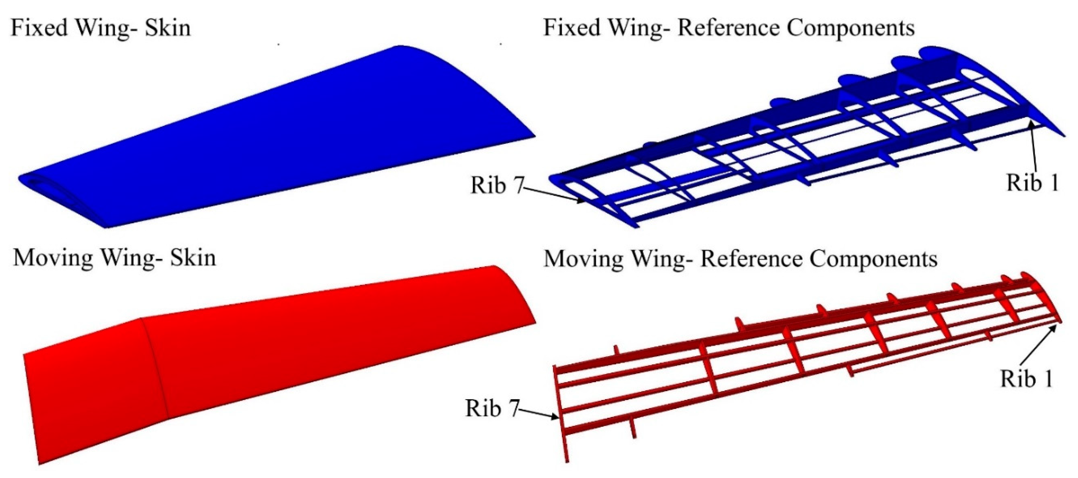
Figure 2.
Configuration outline of fixed and moving segments with allocated wing components based on topology optimization.
Figure 2.
Configuration outline of fixed and moving segments with allocated wing components based on topology optimization.
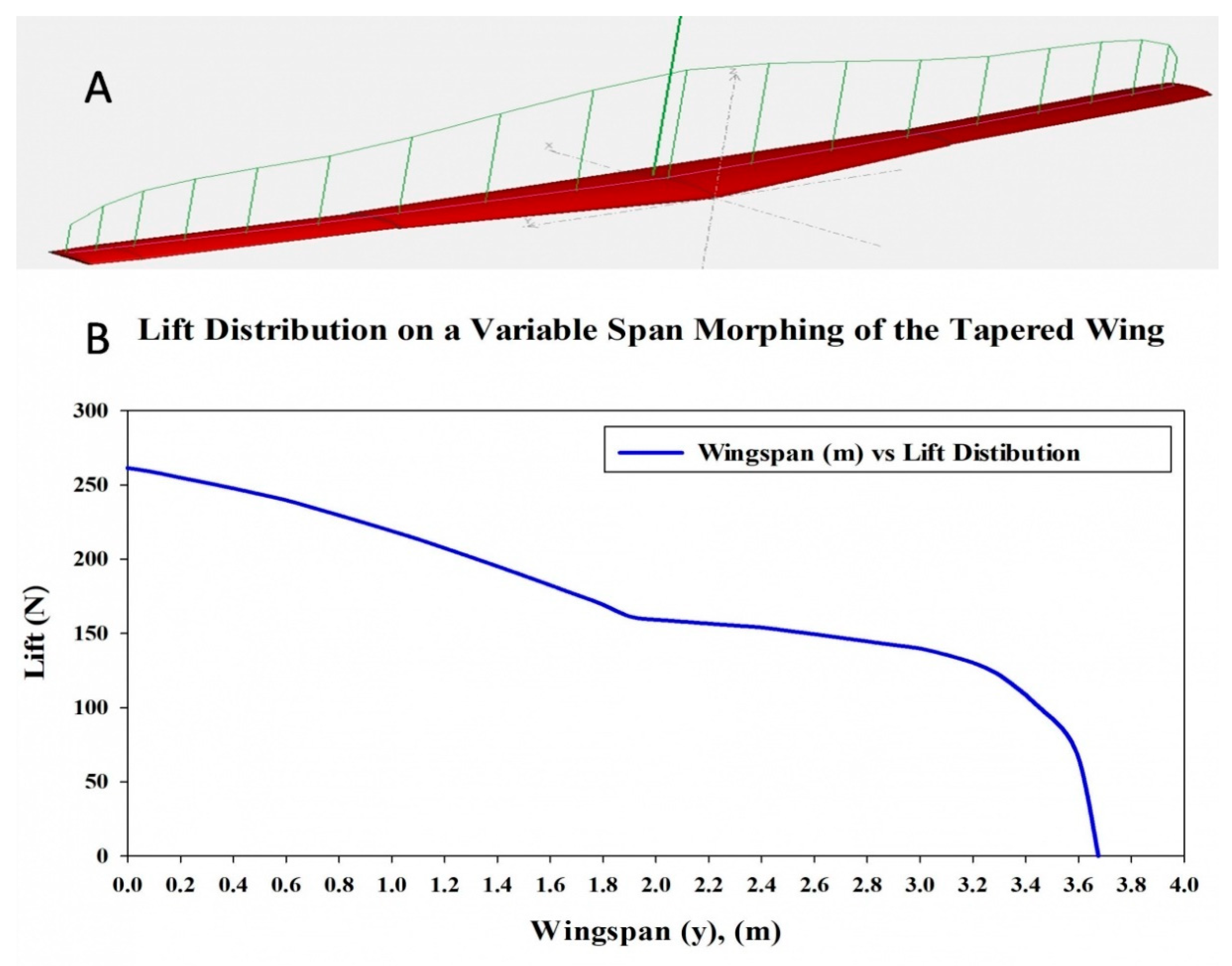
Figure 3.
(A) Lift distributions for the MVSTW calculated using Fluent XFLR5 code; (B) lift force distribution chart.
Figure 3.
(A) Lift distributions for the MVSTW calculated using Fluent XFLR5 code; (B) lift force distribution chart.
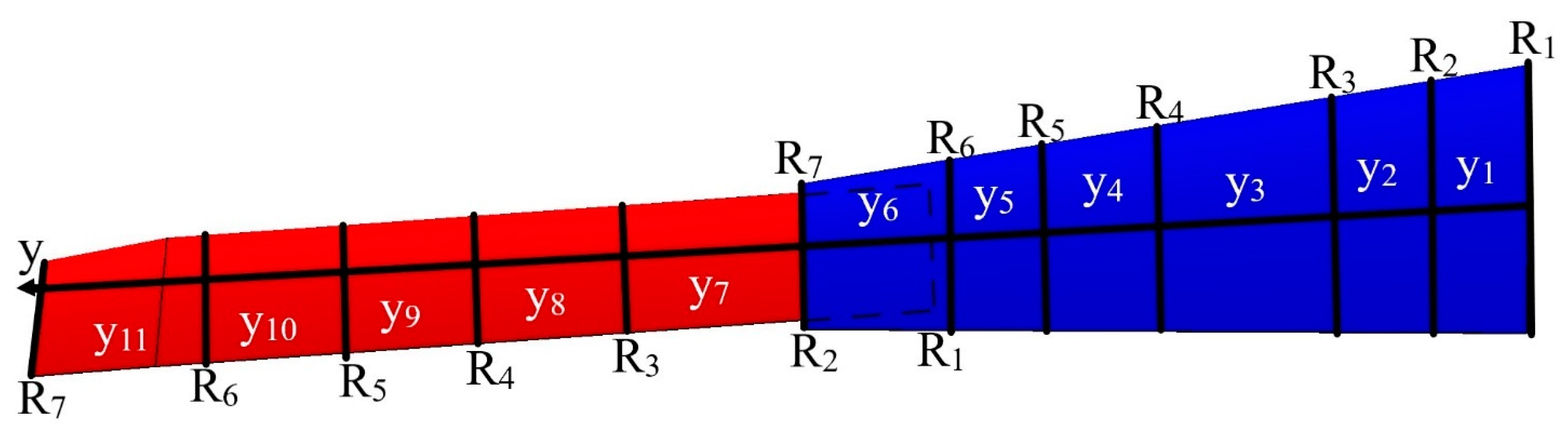
Figure 4.
General scheme of an MVSTW with span sections (yn) and chord numbers ].
Figure 4.
General scheme of an MVSTW with span sections (yn) and chord numbers ].
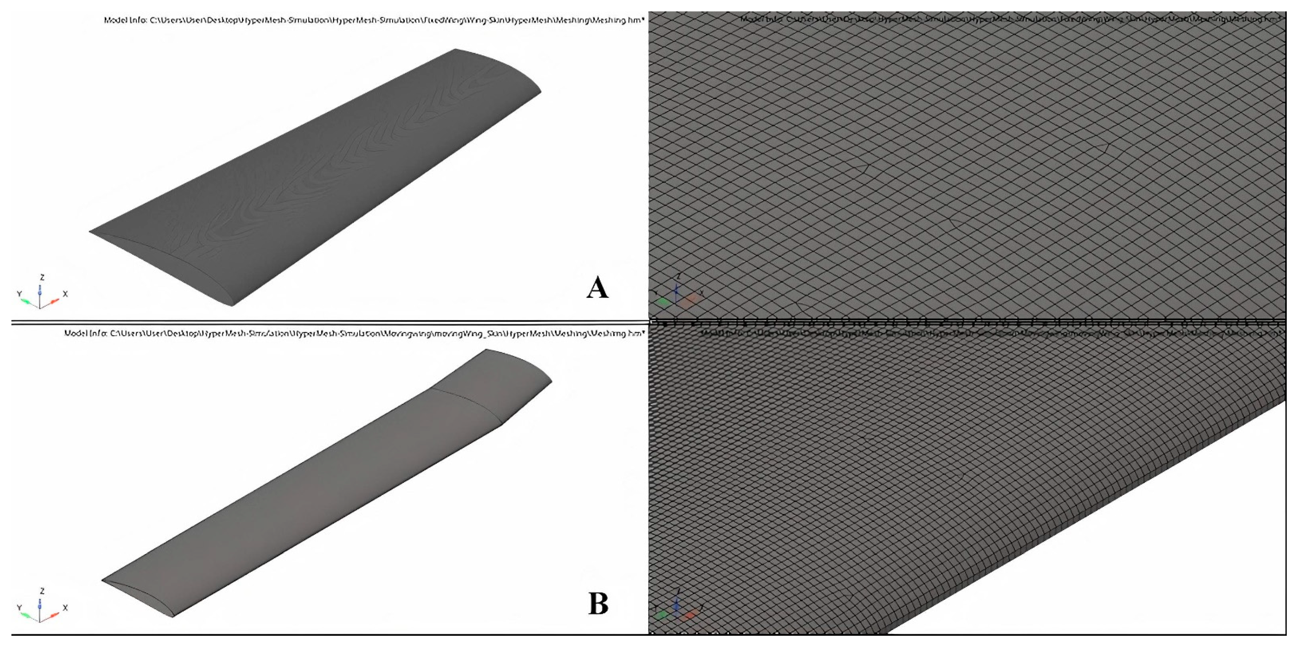
Figure 5.
Meshing method for (A) fixed wing and (B) moving wing.
Figure 5.
Meshing method for (A) fixed wing and (B) moving wing.
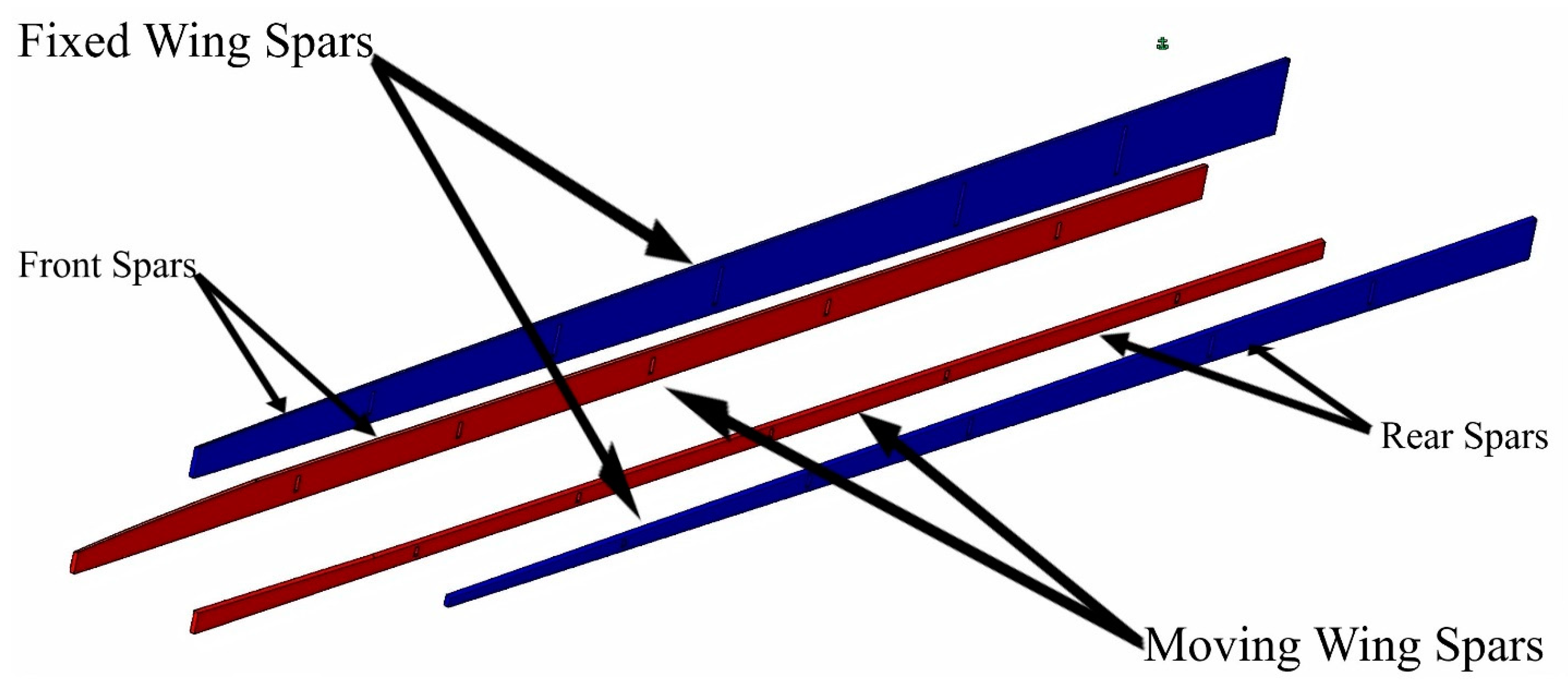
Figure 6.
Baseline geometrical shape for morphing wing spars at their initial position for fixed and moving segments.
Figure 6.
Baseline geometrical shape for morphing wing spars at their initial position for fixed and moving segments.
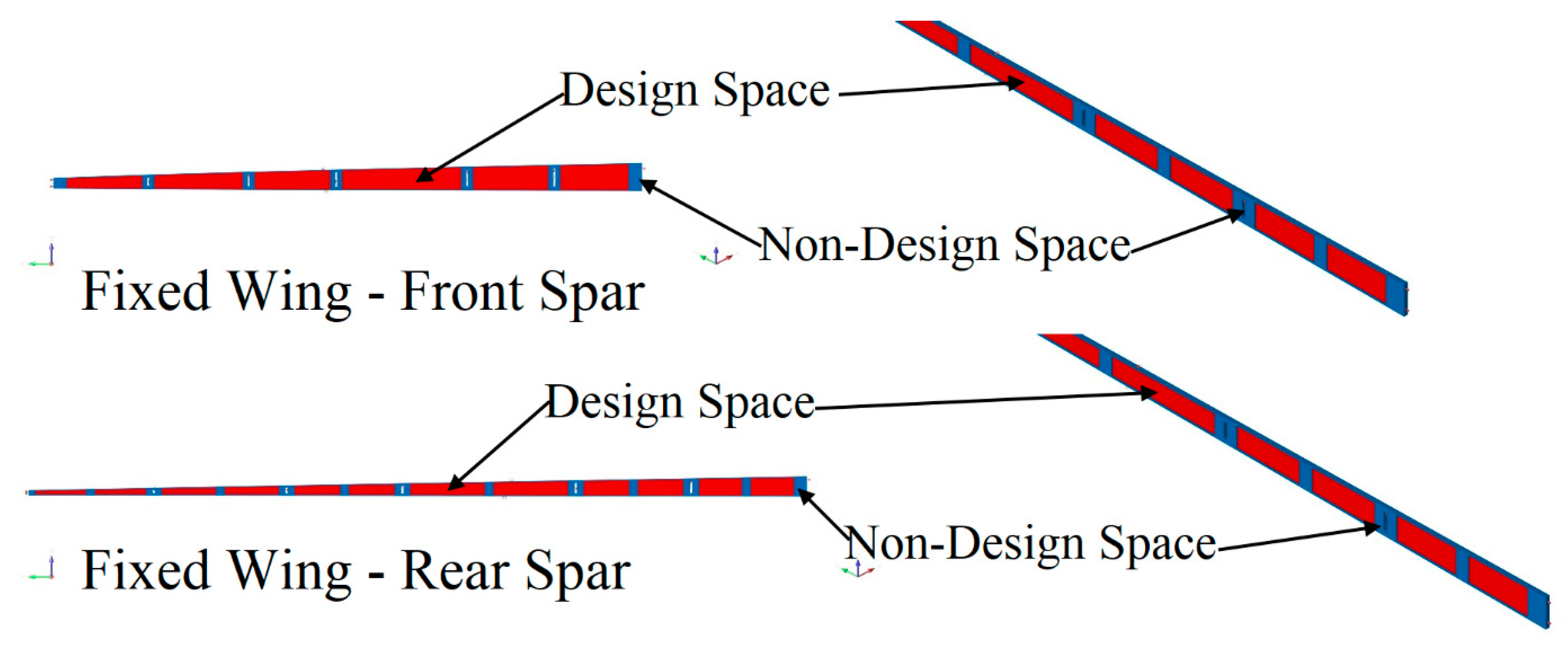
Figure 7.
Boundary conditions with design and non-design spaces for the front and rear spars of a fixed wing.
Figure 7.
Boundary conditions with design and non-design spaces for the front and rear spars of a fixed wing.
Figure 8.
Boundary conditions with design and non-design spaces for the front and rear spars of a moving wing.
Figure 8.
Boundary conditions with design and non-design spaces for the front and rear spars of a moving wing.
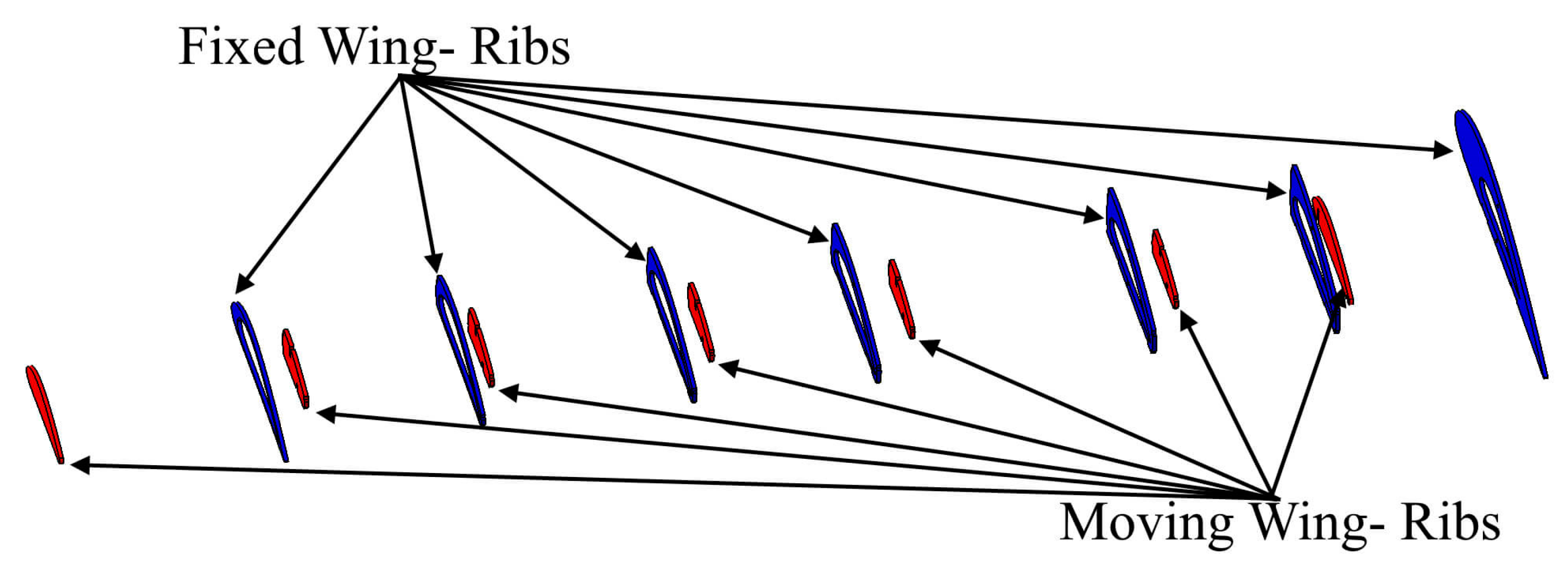
Figure 9.
The geometric shape of morphing wing ribs for fixed and moving wings.
Figure 9.
The geometric shape of morphing wing ribs for fixed and moving wings.
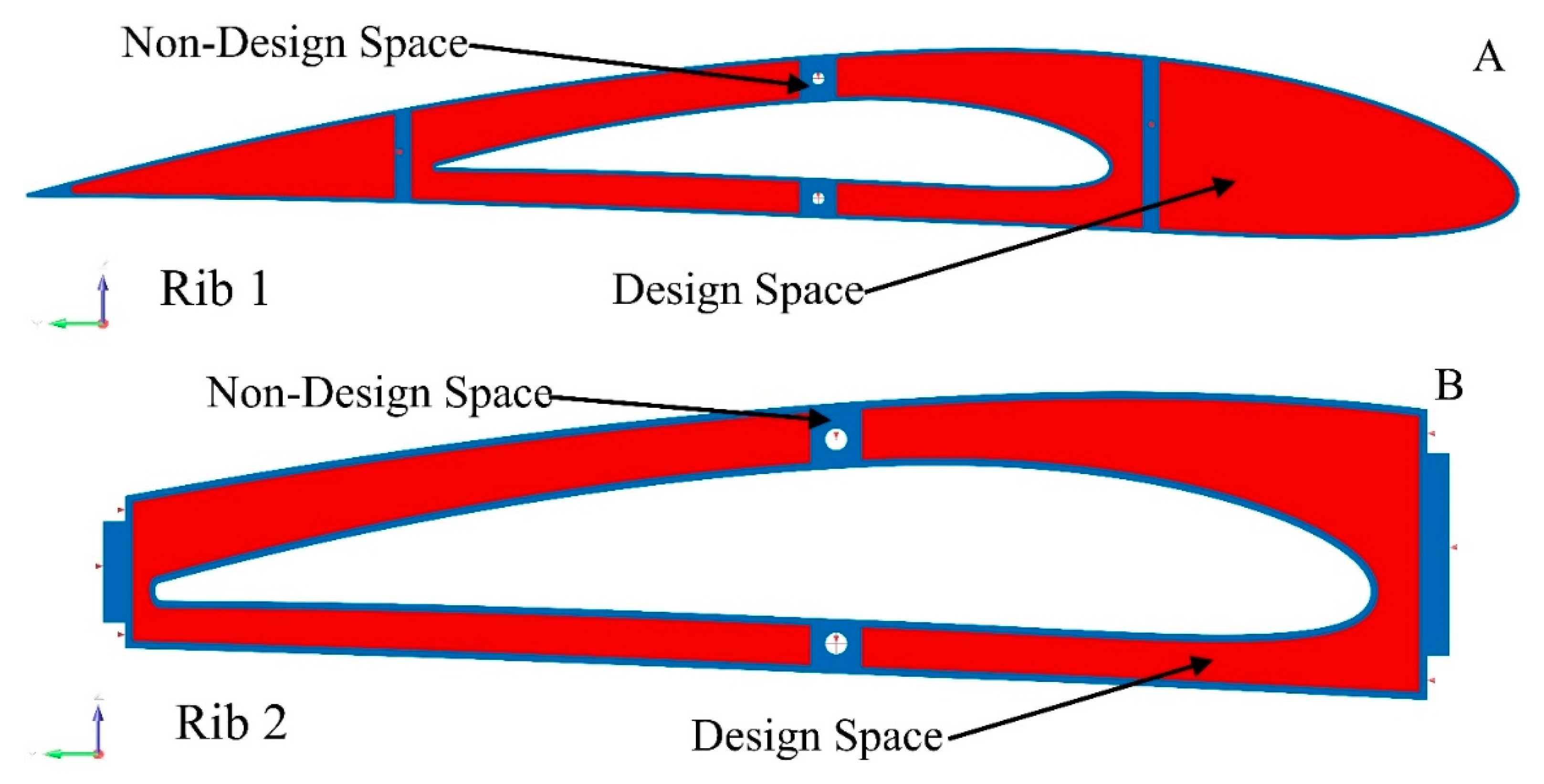
Figure 10.
Examples of the boundary conditions, designable space, and non-designable space for ribs 1 and 2 of the fixed wing.
Figure 10.
Examples of the boundary conditions, designable space, and non-designable space for ribs 1 and 2 of the fixed wing.
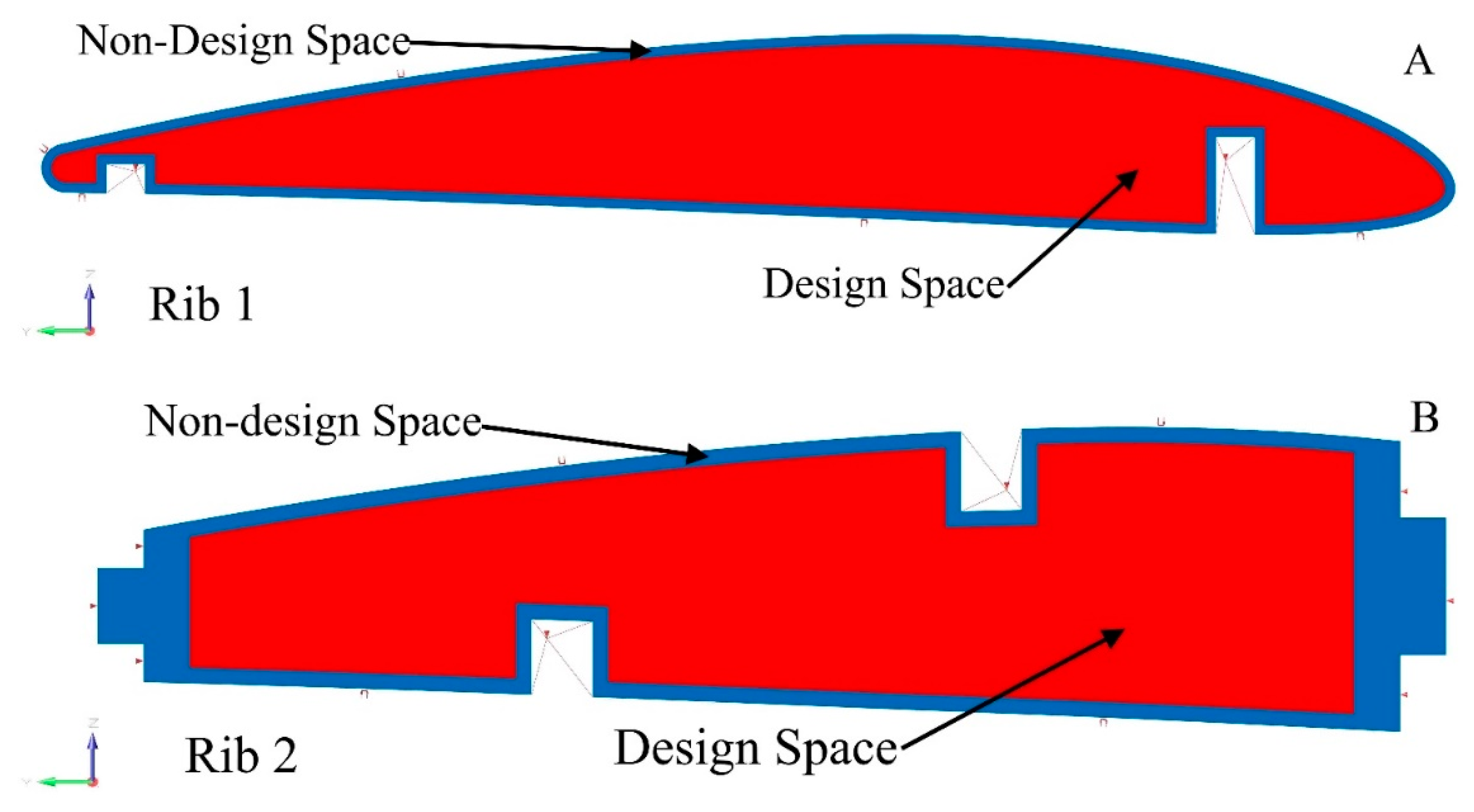
Figure 11.
Examples of the boundary conditions, designable space, and non-designable space of ribs 1 and 2 of the moving wing as an example.
Figure 11.
Examples of the boundary conditions, designable space, and non-designable space of ribs 1 and 2 of the moving wing as an example.
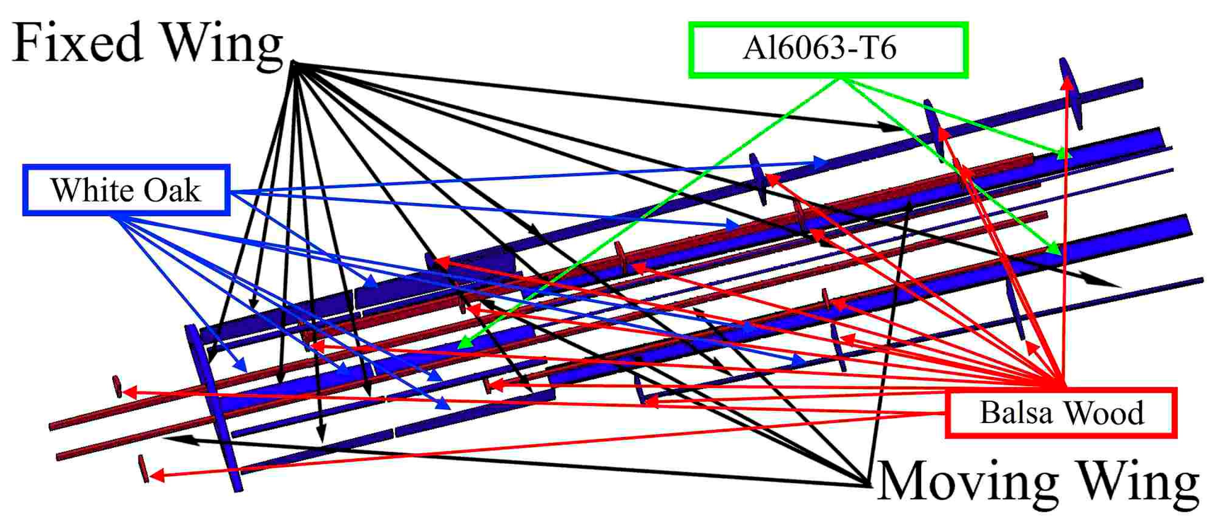
Figure 12.
Support elements with their materials for each wing component for fixed and moving wings at their original positions.
Figure 12.
Support elements with their materials for each wing component for fixed and moving wings at their original positions.
Figure 13.
Boundary conditions, designable space, and non-designable space as examples for support elements (leading-edge rib 1, trailing-edge rib 1, and bottom support plate between ribs 5 and 6) for a fixed wing.
Figure 13.
Boundary conditions, designable space, and non-designable space as examples for support elements (leading-edge rib 1, trailing-edge rib 1, and bottom support plate between ribs 5 and 6) for a fixed wing.
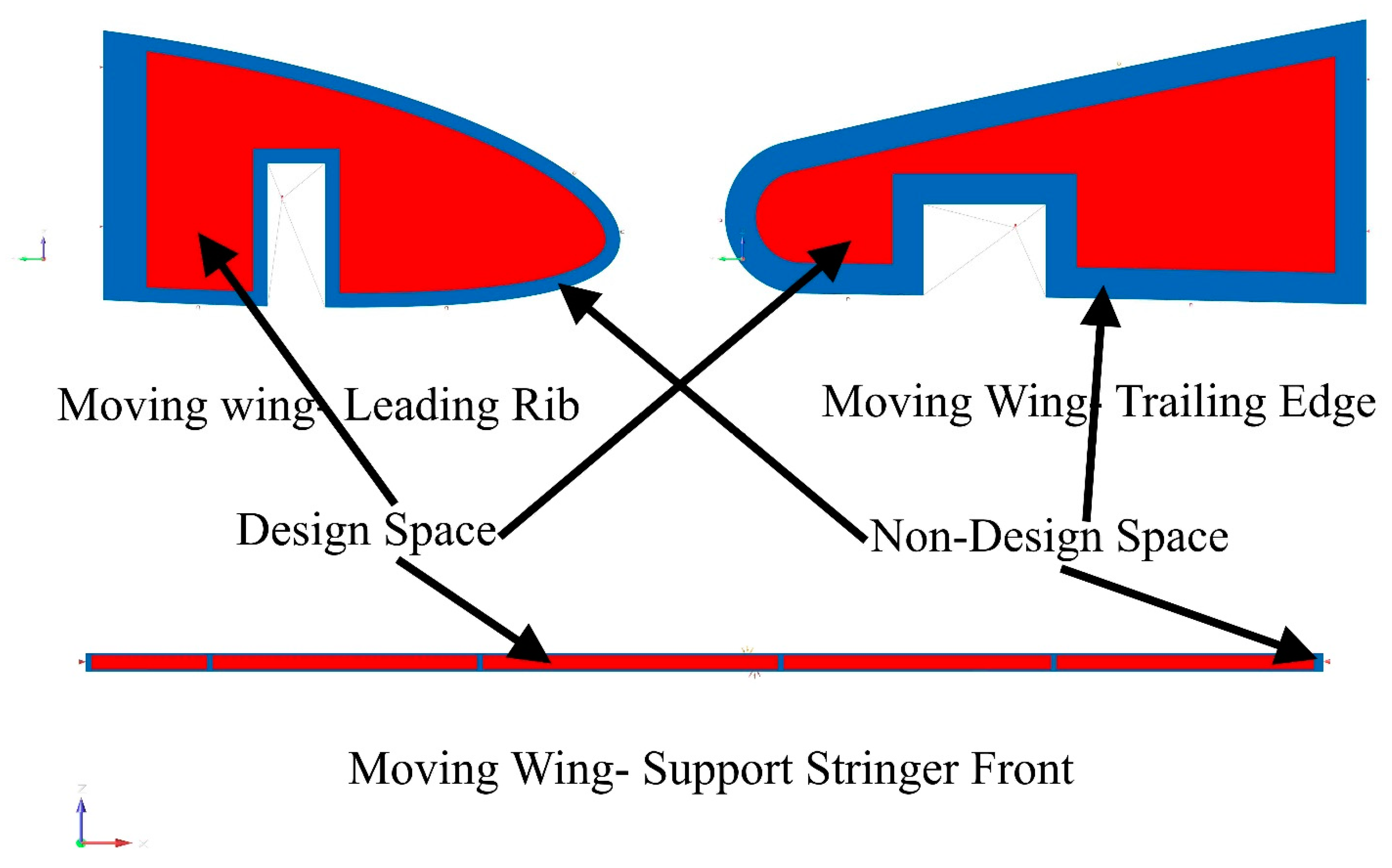
Figure 14.
Boundary conditions, designable space, and non-designable space as examples for support elements (leading-edge rib, trailing-edge rib, and support stringer front) for a moving wing.
Figure 14.
Boundary conditions, designable space, and non-designable space as examples for support elements (leading-edge rib, trailing-edge rib, and support stringer front) for a moving wing.
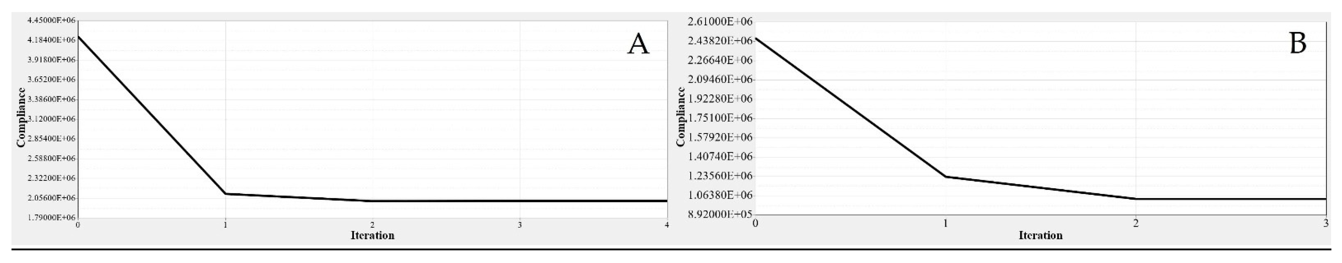
Figure 15.
The objective function convergence graphs for (A) fixed wing skin and (B) moving wing skin.
Figure 15.
The objective function convergence graphs for (A) fixed wing skin and (B) moving wing skin.
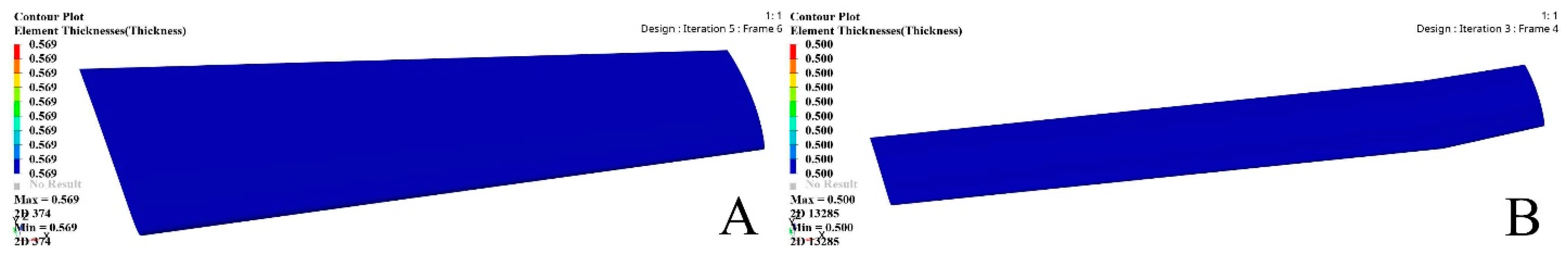
Figure 16.
The thickness obtained based on sizing optimization (SO) results for (A) fixed wing and (B) moving wing.
Figure 16.
The thickness obtained based on sizing optimization (SO) results for (A) fixed wing and (B) moving wing.
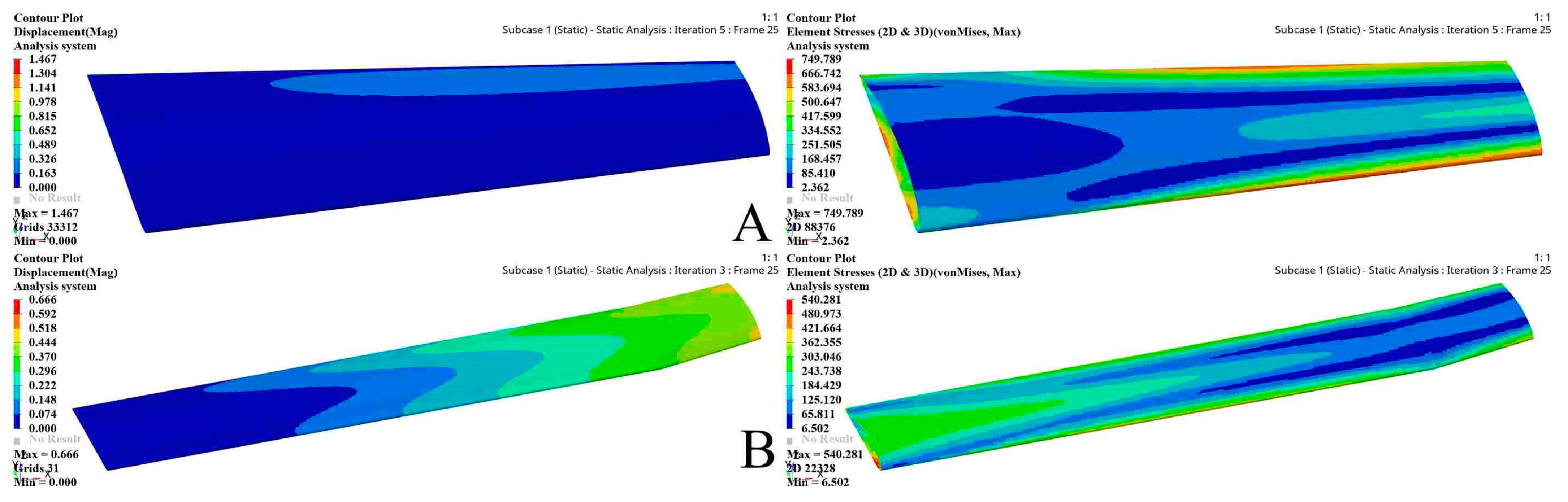
Figure 17.
The sizing optimization problem FEM results for fixed (A) and moving (B) wing segments.
Figure 17.
The sizing optimization problem FEM results for fixed (A) and moving (B) wing segments.
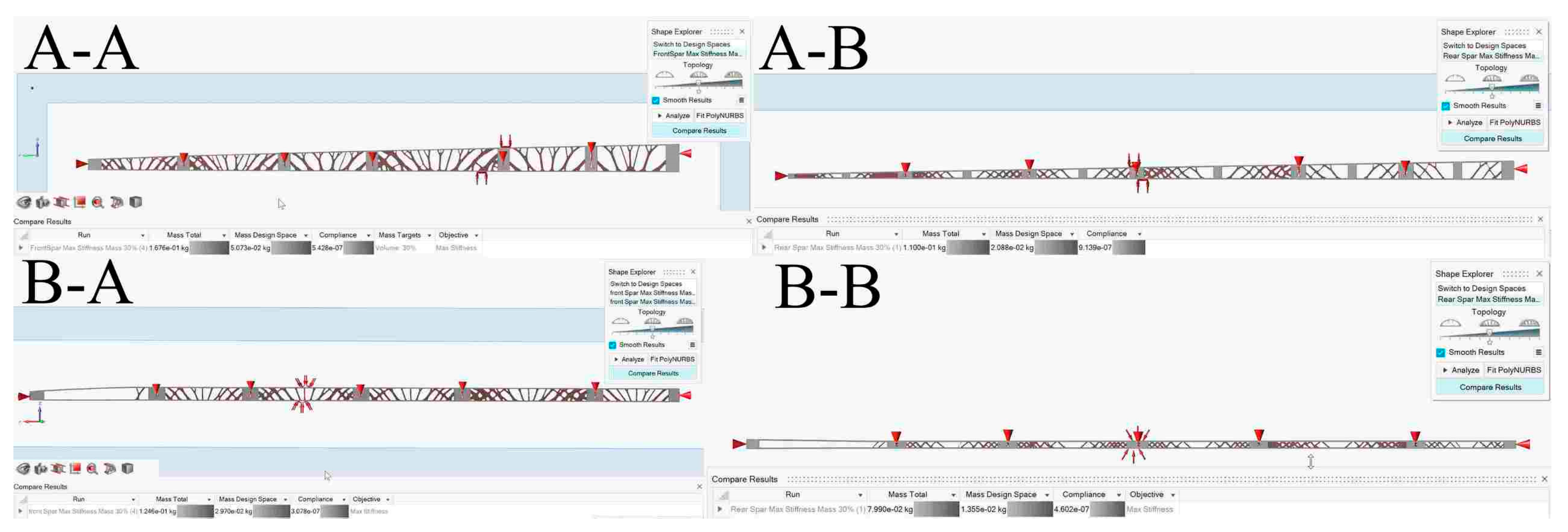
Figure 18.
Variation in element density obtained using the TO for (A-A) fixed wing front spar, (A-B) fixed wing rear spar, (B-A) moving wing front spar, and (B-B) moving wing rear spar.
Figure 18.
Variation in element density obtained using the TO for (A-A) fixed wing front spar, (A-B) fixed wing rear spar, (B-A) moving wing front spar, and (B-B) moving wing rear spar.
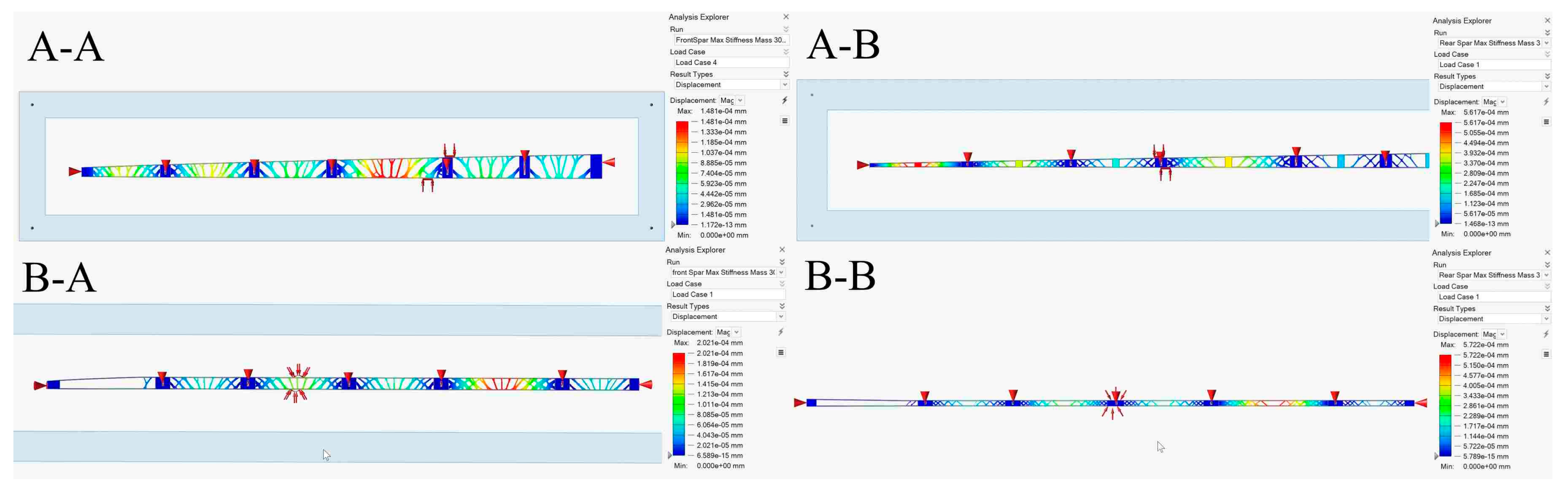
Figure 19.
Displacement values obtained using the TO for (A-A) fixed wing front spar, (A-B) fixed wing rear spar, (B-A) moving wing front spar, and (B-B) moving wing rear spar.
Figure 19.
Displacement values obtained using the TO for (A-A) fixed wing front spar, (A-B) fixed wing rear spar, (B-A) moving wing front spar, and (B-B) moving wing rear spar.
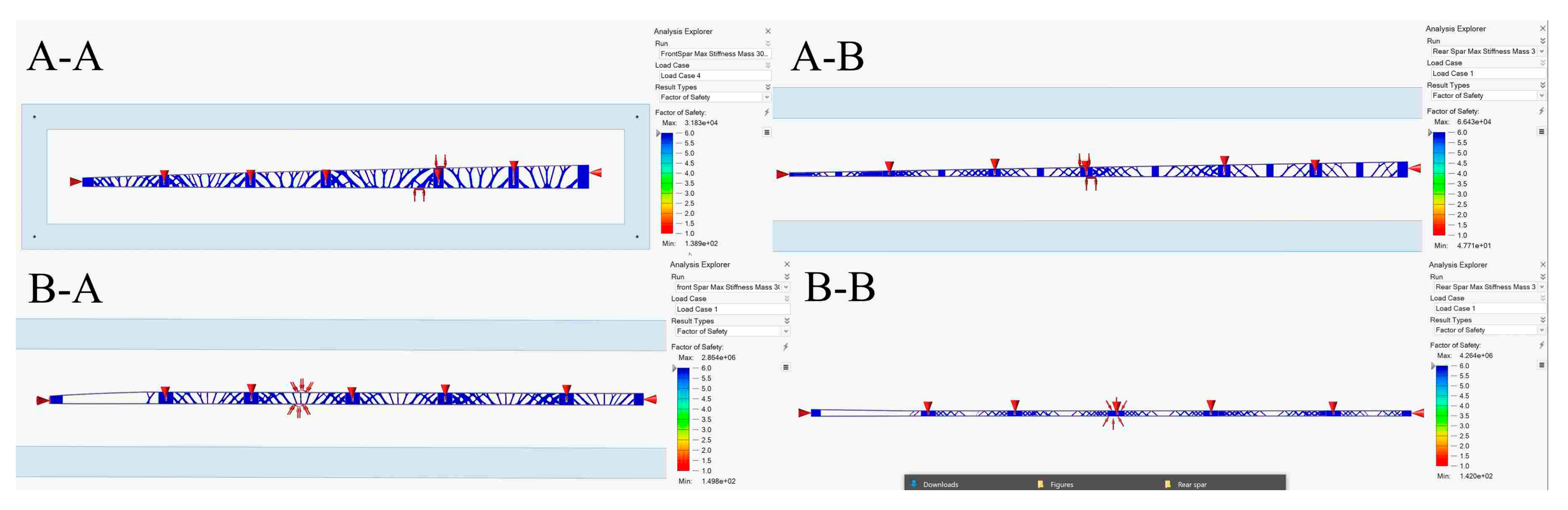
Figure 20.
Safety factor evaluations obtained using the TO for (A-A) fixed wing front spar, (A-B) fixed wing rear spar, (B-A) moving wing front spar, and (B-B) moving wing rear spar.
Figure 20.
Safety factor evaluations obtained using the TO for (A-A) fixed wing front spar, (A-B) fixed wing rear spar, (B-A) moving wing front spar, and (B-B) moving wing rear spar.
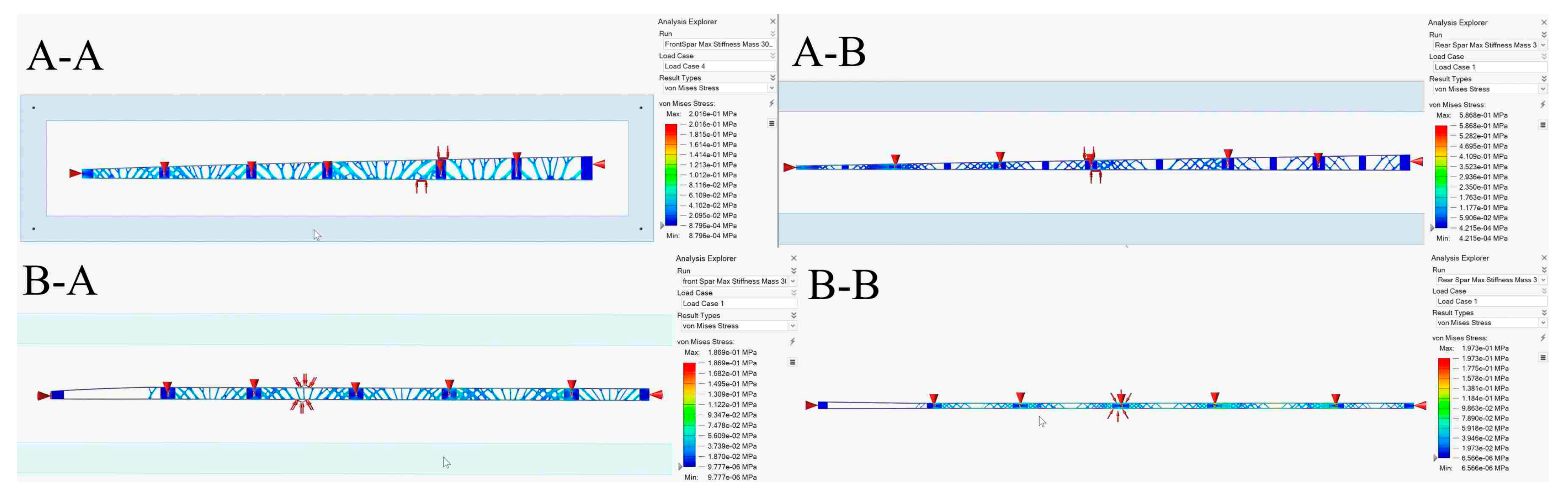
Figure 21.
Von mises stress values obtained using the TO for (A-A) fixed wing front spar, (A-B) fixed wing rear spar, (B-A) moving wing front spar, and (B-B) moving wing rear spar.
Figure 21.
Von mises stress values obtained using the TO for (A-A) fixed wing front spar, (A-B) fixed wing rear spar, (B-A) moving wing front spar, and (B-B) moving wing rear spar.
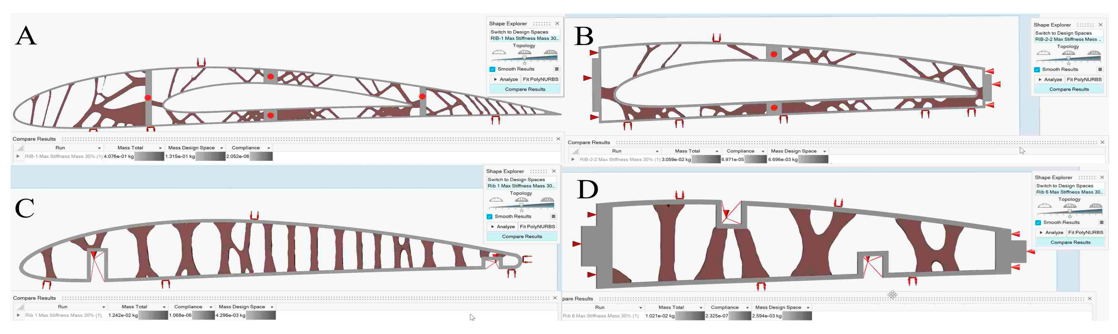
Figure 22.
Variation in element density obtained using TO for (A) fixed wing rib 1, (B) fixed wing rib 2, (C) moving wing rib 1, and (D) moving wing rib 6.
Figure 22.
Variation in element density obtained using TO for (A) fixed wing rib 1, (B) fixed wing rib 2, (C) moving wing rib 1, and (D) moving wing rib 6.
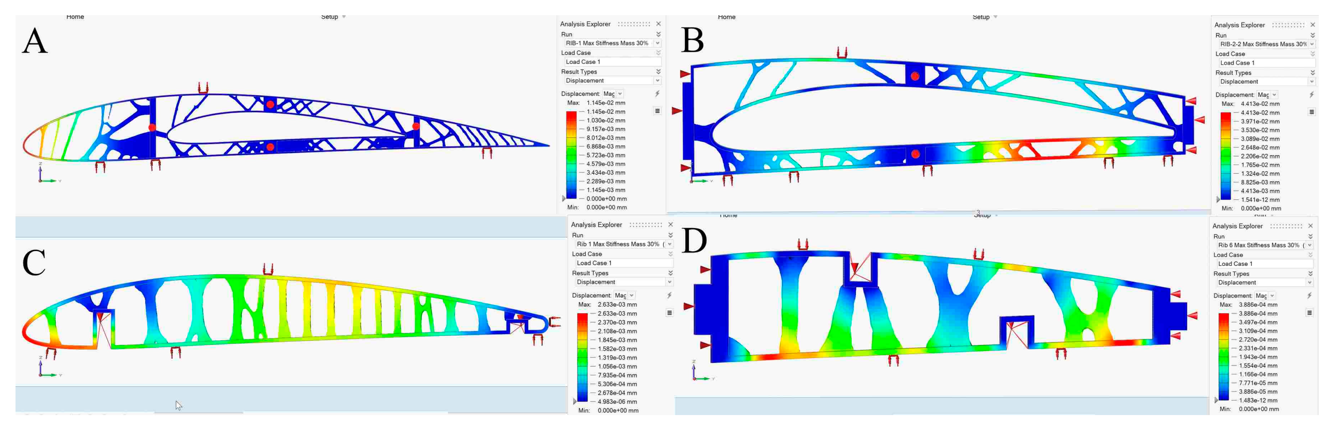
Figure 23.
Displacement values obtained using TO for (A) fixed wing rib 1, (B) fixed wing rib 2, (C) moving wing rib 1, and (D) moving wing rib 6.
Figure 23.
Displacement values obtained using TO for (A) fixed wing rib 1, (B) fixed wing rib 2, (C) moving wing rib 1, and (D) moving wing rib 6.
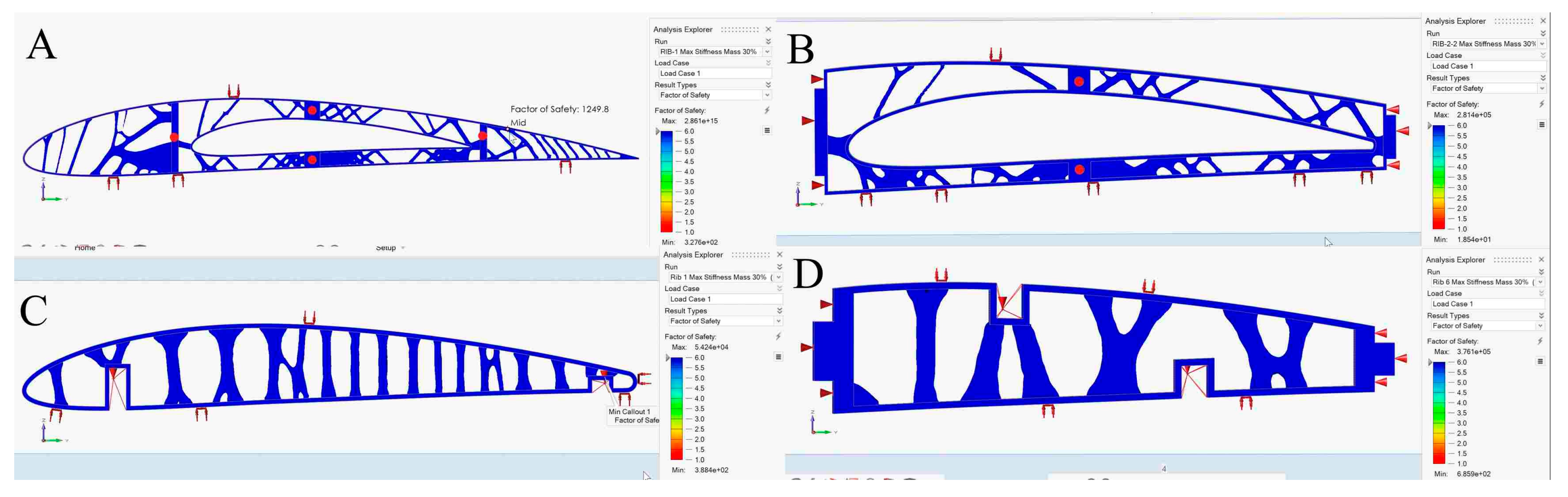
Figure 24.
Safety factor evaluations obtained using TO for (A) fixed wing rib 1, (B) fixed wing rib 2, (C) moving wing rib 1, and (D) moving wing rib 6.
Figure 24.
Safety factor evaluations obtained using TO for (A) fixed wing rib 1, (B) fixed wing rib 2, (C) moving wing rib 1, and (D) moving wing rib 6.
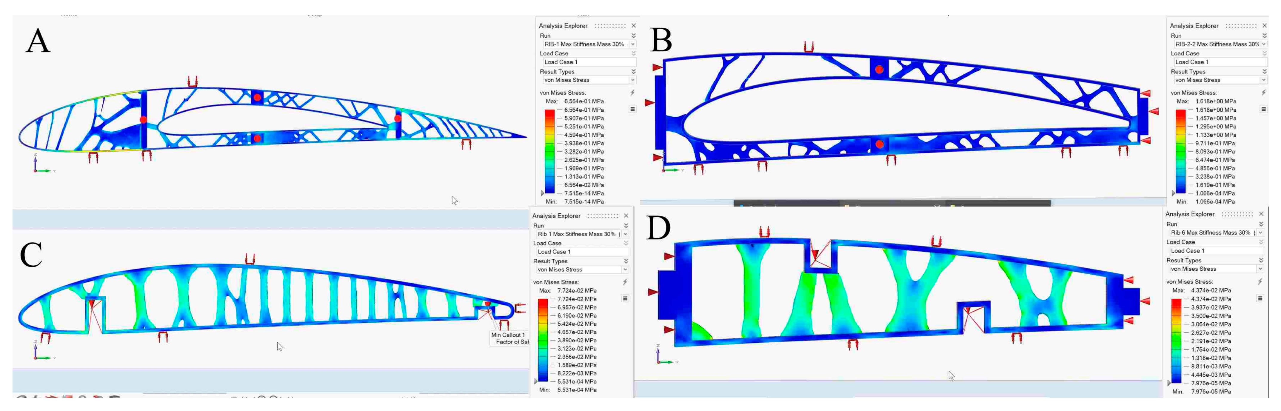
Figure 25.
Von mises stress values obtained using TO for (A) fixed wing rib 1, (B) fixed wing rib 2, (C) moving wing rib 1, and (D) moving wing rib 6.
Figure 25.
Von mises stress values obtained using TO for (A) fixed wing rib 1, (B) fixed wing rib 2, (C) moving wing rib 1, and (D) moving wing rib 6.
Figure 26.
Variation in element density in relation to TO results of a fixed wing: (A) leading edge of rib 1, (B) trailing edge of rib 1, (C) bottom support surface between rib 6 and rib 7, and (D) front spar support.
Figure 26.
Variation in element density in relation to TO results of a fixed wing: (A) leading edge of rib 1, (B) trailing edge of rib 1, (C) bottom support surface between rib 6 and rib 7, and (D) front spar support.
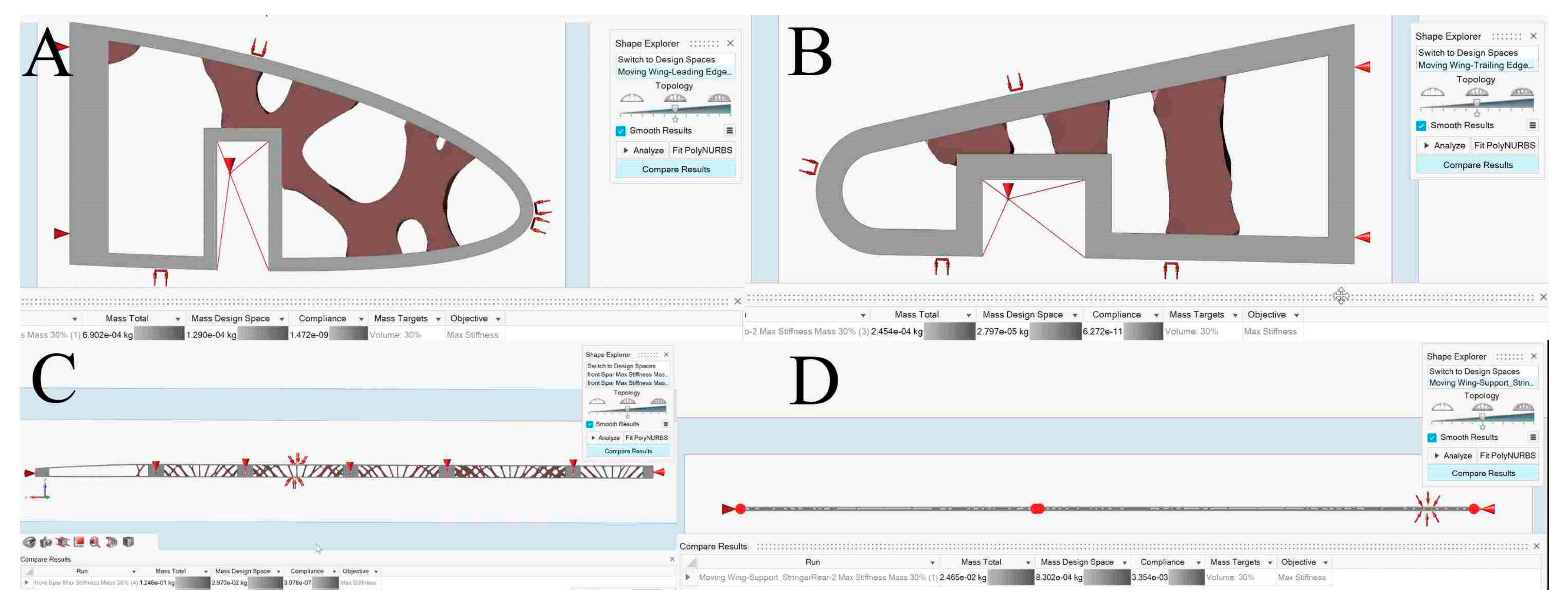
Figure 27.
Variation in element density obtained using TO for a moving wing: (A) leading edge of rib 1, (B) trailing edge of rib 1, (C) support stringer of a front spar, and (D) support stringer of a rear spar.
Figure 27.
Variation in element density obtained using TO for a moving wing: (A) leading edge of rib 1, (B) trailing edge of rib 1, (C) support stringer of a front spar, and (D) support stringer of a rear spar.
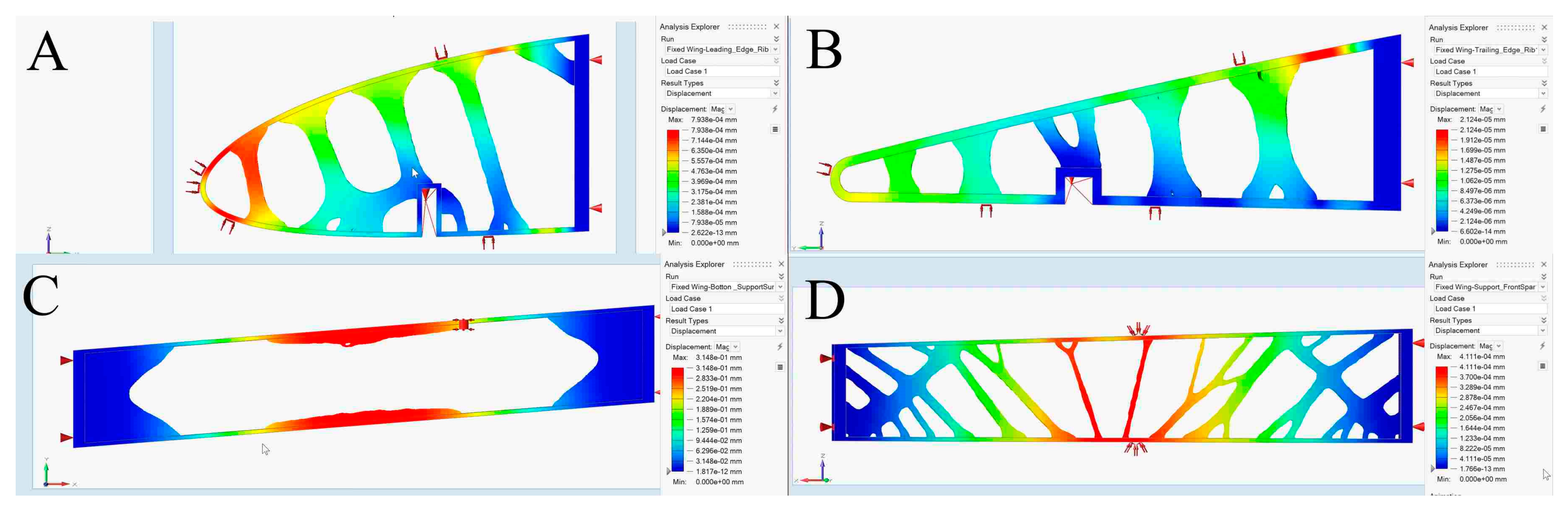
Figure 28.
Displacement values in relation to topology optimization results of a fixed wing: (A) leading edge of rib 1, (B) trailing edge of rib 1, (C) bottom support surface between ribs 6 and 7, and (D) support of a front spar.
Figure 28.
Displacement values in relation to topology optimization results of a fixed wing: (A) leading edge of rib 1, (B) trailing edge of rib 1, (C) bottom support surface between ribs 6 and 7, and (D) support of a front spar.
Figure 29.
Safety factor evaluations obtained using TO for a fixed wing: (A) leading edge of rib 1, the (B) trailing edge of rib 1, (C) bottom support surface between ribs 6 and 7, and (D) support of a front spar.
Figure 29.
Safety factor evaluations obtained using TO for a fixed wing: (A) leading edge of rib 1, the (B) trailing edge of rib 1, (C) bottom support surface between ribs 6 and 7, and (D) support of a front spar.
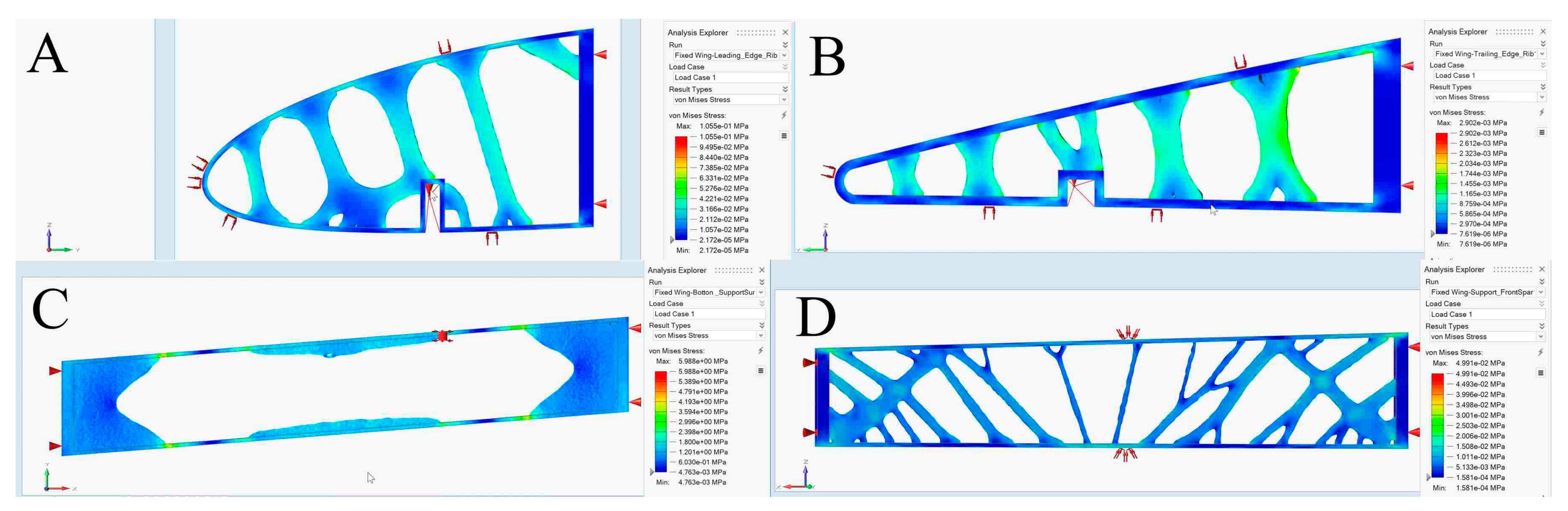
Figure 30.
Von mises stress values obtained using TO for a fixed wing: (A) leading edge of rib 1, (B) trailing edge of rib 1, (C) bottom support surface between ribs 6 and 7, and (D) support of a front spar.
Figure 30.
Von mises stress values obtained using TO for a fixed wing: (A) leading edge of rib 1, (B) trailing edge of rib 1, (C) bottom support surface between ribs 6 and 7, and (D) support of a front spar.
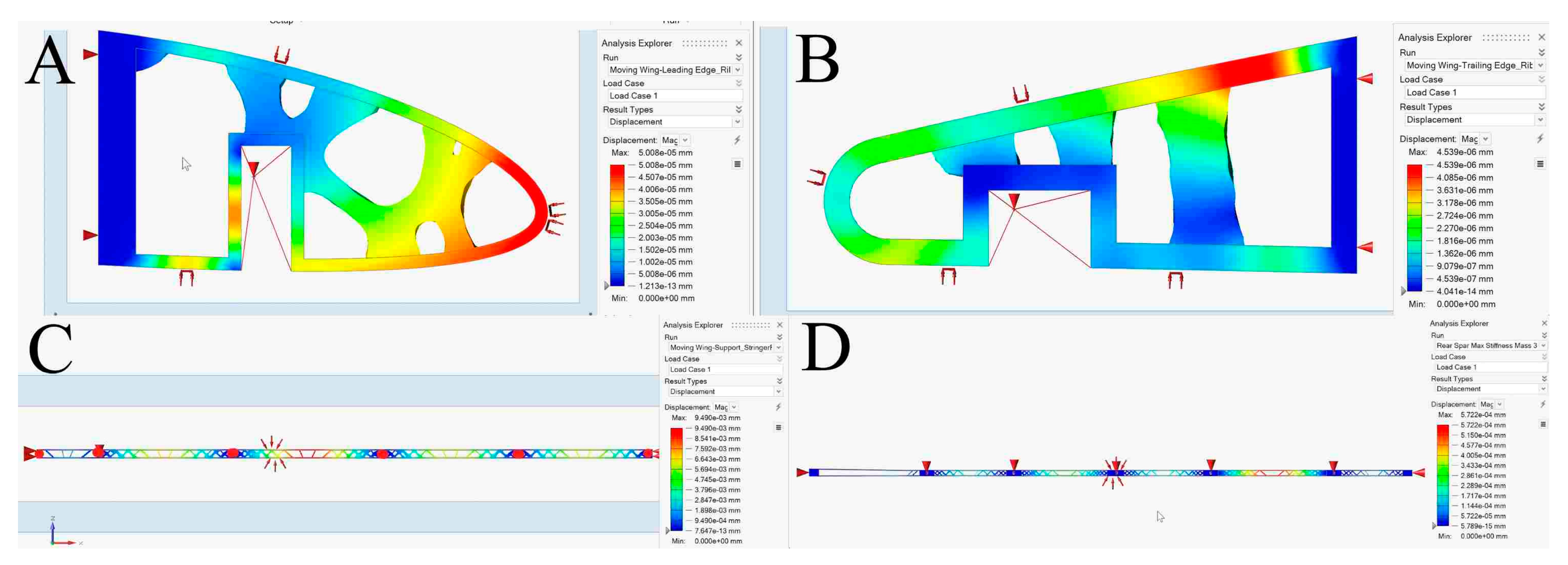
Figure 31.
Displacement values obtained using TO for a moving wing: (A) leading edge of rib 1, (B) trailing edge of rib 1, (C) support stringer of a front spar, and (D) support stringer of a rear spar.
Figure 31.
Displacement values obtained using TO for a moving wing: (A) leading edge of rib 1, (B) trailing edge of rib 1, (C) support stringer of a front spar, and (D) support stringer of a rear spar.
Figure 32.
Safety factor evaluations obtained using TO for a moving wing: (A) leading edge of rib 1, (B) trailing edge of rib 1, (C) support stringer of a front spar, and (D) support stringer of a rear spar.
Figure 32.
Safety factor evaluations obtained using TO for a moving wing: (A) leading edge of rib 1, (B) trailing edge of rib 1, (C) support stringer of a front spar, and (D) support stringer of a rear spar.
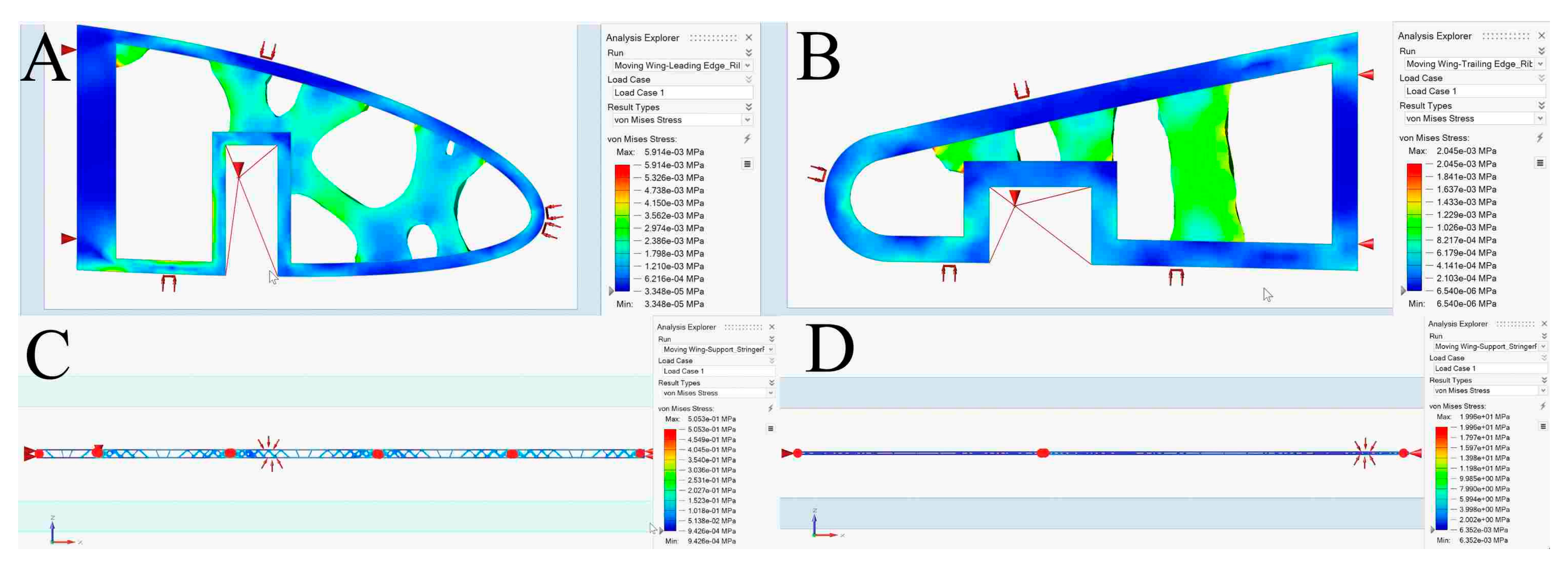
Figure 33.
Von mises stress values obtained using TO for a moving wing: (A) leading edge of rib 1, (B) trailing edge of rib 1, (C) support stringer of a front spar, and (D) support stringer of a rear spar.
Figure 33.
Von mises stress values obtained using TO for a moving wing: (A) leading edge of rib 1, (B) trailing edge of rib 1, (C) support stringer of a front spar, and (D) support stringer of a rear spar.
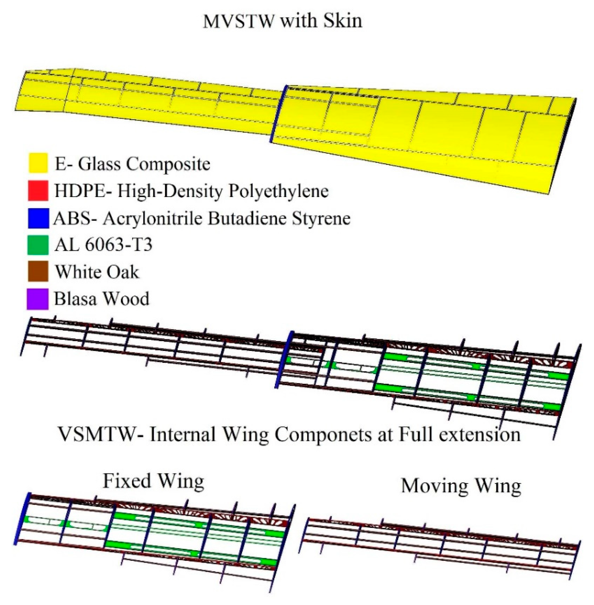
Figure 34.
MVSTW remodeled in detail, using composite materials for its components.
Figure 34.
MVSTW remodeled in detail, using composite materials for its components.
Table 1.
The characteristics of the UAS-S4.
Table 1.
The characteristics of the UAS-S4.
| Geometrical Data | Values |
|---|
| Wing Span | 4.2 m |
| Wing Area | 2.3 m2 |
| Total length | 2.5 m |
| Mean Aerodynamic Chord (MAC) | 0.57 m |
| Empty weight | 50 kg |
| Maximum Take-off Weight (MTOW) | 80 kg |
| Loitering Airspeed | 35 knots |
| Maximum Speed | 135 knots |
| Service Ceiling | 15,000 ft |
| Operational Range | 120 km |
Table 2.
Proposed wing rib locations for fixed and moving segments, as measured for reference rib no. 1.
Table 2.
Proposed wing rib locations for fixed and moving segments, as measured for reference rib no. 1.
| Rib No. | Fixed Wing | Moving Wing |
|---|
| 1. | 0 mm reference | 0 mm reference |
| 2. | 269 mm | 245 mm |
| 3. | 534 mm | 626 mm |
| 4. | 932 mm | 919 mm |
| 5. | 1198 mm | 1234 mm |
| 6. | 1503 mm | 1502 mm |
| 7. | 1800 mm | 1875 mm |
Table 3.
Lifting loads computed for each section of an MVSTW.
Table 3.
Lifting loads computed for each section of an MVSTW.
| Section Number | Lift Load (N) | Ultimate Load |
|---|
| y1 | 257.36 | 1158.1 |
| y2 | 243.77 | 1096.97 |
| y3 | 232.15 | 1044.65 |
| y4 | 213.325 | 959.96 |
| y5 | 198.29 | 892.28 |
| y6 | 175.96 | 791.8 |
| y7 | 158.62 | 713.77 |
| y8 | 152.7 | 687.15 |
| y9 | 147.12 | 662.04 |
| y10 | 134.61 | 605.75 |
| y11 | 79.11 | 355.995 |
Table 4.
Material properties of E-glass composite applied in the Sizing Optimization of the wing skin.
Table 4.
Material properties of E-glass composite applied in the Sizing Optimization of the wing skin.
| Parameter | Value |
|---|
| Young’s modulus (quasi-isotropic) | 30.578 GPa |
| Poisson’s ratio | 0.138 |
| Yield strength | 901.097 MPa |
| Ultimate strength | 1351.645 MPa |
| Density | |
Table 5.
Material properties of HDPE applied in the topology optimization of the wing spars.
Table 5.
Material properties of HDPE applied in the topology optimization of the wing spars.
| Parameter | Value |
|---|
| Young’s modulus | 1250 MPa |
| Poisson’s ratio | 0.4 |
| Yield strength | 28 MPa |
| Ultimate strength | 48 MPa |
| Density | 0.95 |
Table 6.
Material properties of ABS applied in the topology optimization of the wing ribs.
Table 6.
Material properties of ABS applied in the topology optimization of the wing ribs.
| Parameter | Value |
|---|
| Young’s modulus | 2000 MPa |
| Poisson’s ratio | 0.36 |
| Yield strength | 30 MPa |
| Ultimate strength | 36 MPa |
| Density | |
Table 7.
Material properties of balsa wood applied in the topology optimization of the wing support elements.
Table 7.
Material properties of balsa wood applied in the topology optimization of the wing support elements.
| Parameter | Value |
|---|
| Young’s modulus | 3.4 GPa |
| Poisson’s ratio | 0.23 |
| Yield strength | 21.6 MPa |
| Ultimate strength | 21.6 MPa |
| Density | |
Table 8.
Material properties of white oak applied in the topology optimization of the wing support elements.
Table 8.
Material properties of white oak applied in the topology optimization of the wing support elements.
| Parameter | Value |
|---|
| Young’s modulus | 12.27 MPa |
| Poisson’s ratio | 0.369 |
| Yield strength | 104.8 MPa |
| Ultimate strength | 104.8 MPa |
| Density | |
Table 9.
Material properties of aluminum alloy 6063-T6 applied in the topology optimization of the wing support elements.
Table 9.
Material properties of aluminum alloy 6063-T6 applied in the topology optimization of the wing support elements.
| Parameter | Value |
|---|
| Young’s modulus | 68.9 GPa |
| Poisson’s ratio | 0.33 |
| Yield strength | 214 MPa |
| Ultimate strength | 241 MPa |
| Density | |
Table 10.
Evaluations obtained via SO and FEM for the wing skins for both wing segments.
Table 10.
Evaluations obtained via SO and FEM for the wing skins for both wing segments.
| | Iterations | Deformation | Stress | Original Skin
Thickness | Optimized Skin
Thickness | Weight Reduction
Ratio |
|---|
| Fixed Wing | 5 | 1.47 mm | 749.79 MPa | 2 mm | 0.569 mm | 81.45% |
| Moving Wing | 3 | 0.67 mm | 540.29 MPa | 2 mm | 0.500 mm | 81.80% |
Table 11.
The parameters of the wing segments for spars were determined by TO using Finite Element Analysis (FEA).
Table 11.
The parameters of the wing segments for spars were determined by TO using Finite Element Analysis (FEA).
| | Fixed Wing | Moving Wing |
|---|
| Front Spar | Rear Spar | Front Spar | Rear Spar |
|---|
| Initial Weight | 0.29 kg | 0.16 kg | 0.19 kg | 0.59 kg |
| Optimized Weight | 0.17 kg | 0.11 kg | 0.12 kg | 0.08 kg |
| Weight reduction Ratio | 41.4% | 31.3% | 36.8% | 86.4% |
| Displacement | 0.00015 mm | 0.00056 mm | 0.00020 mm | 0.00057 mm |
| Stress | 0.2016 MPa | 0.3191 MPa | 0.1869 MPa | 0.1973 MPa |
| Safety Factor | 31,830 | 66,130 | 2,864,000 | 4,264,000 |
Table 12.
Topology optimization according to Finite Element Analysis yielded these wing segment parameters for the ribs.
Table 12.
Topology optimization according to Finite Element Analysis yielded these wing segment parameters for the ribs.
| | Initial Weight | Optimized Weight | Weight Reduction Ratio | Deformation | Min Factor of Safety | Stress |
|---|
| Fixed Wing | Rib 1 | 0.094 kg | 0.054 kg | 42.6% | 1.02 mm | 47.5 | 6.31 MPa |
| Rib 2 | 0.0459 kg | 0.0305 kg | 32.6% | 0.0044 mm | 18.5 | 1.62 MPa |
| Rib 3 | 0.042 kg | 0.029 kg | 31% | 0.05 mm | 38.9 | 0.77 MPa |
| Rib 4 | 0.035 kg | 0.026 kg | 25.7% | 0.094 mm | 35.7 | 0.84 MPa |
| Rib 5 | 0.031 kg | 0.024 kg | 22.6% | 0.15 mm | 30.7 | 0.98 MPa |
| Rib 6 | 0.029 kg | 0.026 kg | 10.3% | 2.07 mm | 8.9 | 3.38 MPa |
| Rib 7 | 0.033 kg | 0.033 kg | 0 | 0 | | 0 |
| Moving Wing | Rib 1 | 0.022 kg | 0.012 kg | 70.1% | 0.0026 mm | 38.8 | 0.078 MPa |
| Rib 2 | 0.016 kg | 0.01 kg | 37.5% | 0.00078 mm | 310.9 | 0.097 MPa |
| Rib 3 | 0.016 kg | 0.01 kg | 37.5% | 0.00078 mm | 310.9 | 0.097 MPa |
| Rib 4 | 0.016 kg | 0.01 kg | 37.5% | 0.00078 mm | 310.9 | 0.079 MPa |
| Rib 5 | 0.016 kg | 0.01 kg | 37.5% | 0.00037 mm | 68.6 | 0.032 MPa |
| Rib 6 | 0.016 kg | 0.01 kg | 37.5% | 0.00037 mm | 68.6 | 0.027 MPa |
| Rib 7 | 0.044 kg | 0.044 kg | 0 | 0 | | 0 |
Table 13.
Comparison of optimized VSMTW and UAS-S4 wing in terms of aerodynamic performance and weight.
Table 13.
Comparison of optimized VSMTW and UAS-S4 wing in terms of aerodynamic performance and weight.
| | | Aerodynamic Performance | Weight |
|---|
| Lift | Drag | L/D |
|---|
| UAS-S4 wing | | 347.02 N | 16.34 N | 21.2 | 6.5 kg |
| VSMTW at full wing extension | Alu 2024-T3 | 1509.89 N | 45.59 N | 33.1 | 12.4 kg |
| Composite material | 1509.89 N | 45.59 N | 33.1 | 5.5 kg |


