Article

Energy-Harvesting Characteristics of a Dual-Mode Magnetic Suspension for Vehicles: Analysis and Experimental Verification

1
Mechanical Systems Engineering Major, Nippon Institute of Technology, Saitama 345-8501, Japan
2
School of Mechanical Engineering, Shenyang University of Technology, Shenyang 110870, China
3
Shenyang Machine Tool Group Company of Limited Liability, Shenyang 110041, China
4
Department of Mechanical Engineering, Nippon Institute of Technology, Saitama 345-8501, Japan
*
Author to whom correspondence should be addressed.
Actuators 2022, 11(12), 363; https://doi.org/10.3390/act11120363
Submission received: 14 November 2022 / Revised: 29 November 2022 / Accepted: 1 December 2022 / Published: 3 December 2022
(This article belongs to the Special Issue Advanced Theory and Application of Magnetic Actuators)

Abstract

:
The advantages of the proposed dual-mode magnetic suspension are it having a high level of safety and a compact structure compared with the previous studies. However, the structure parameters can affect the energy harvesting of the suspension system. Therefore, this paper aims to analyze the energy-harvesting characteristics of the proposed dual-mode magnetic suspension. Firstly, the structure and working principle of the proposed suspension are introduced. Then, the influences of the various parameters for the actuator on the energy regeneration characteristics are analyzed by the finite element method, such as the magnetic ring, the fixed plug thickness, the heat dissipation, and the air gap, and the actuator parameters are defined by the orthogonal analysis method. Furthermore, the numerical results of the energy harvesting are calculated. Finally, the vibration experimental setup is manufactured, and the simulation analysis is verified by the experiment. The results demonstrate that the excitation amplitude is 3.1 mm, the frequency is 18 Hz, and the maximum induced EMF is 8.8 V. Additionally, compared with passive suspension, the energy harvesting of the proposed suspension has been verified in the laboratory, which lays the foundation for the design and analysis of the dual-mode magnetic suspension in a real vehicle.

1. Introduction

In energy-harvesting suspension, a set of energy regeneration devices is used to replace the traditional damper to alleviate the impact of the road surface and recover the vibration energy of the suspension caused by the road surface excitation during the running of the vehicle. In order to recover and reuse this part of the energy, various forms of energy-harvesting suspensions have been proposed. Since the end of the 1970s, scholars began to theoretically calculate and analyze the feasibility of vibration energy regeneration for vehicle suspension. The current energy-harvesting suspension types mainly include mechanical energy-harvesting suspension [1,2], electro-hydraulic energy harvester [3,4] and electromagnetic energy-harvesting suspension [5,6]. In the energy-harvesting system, the harvested energy from the suspension vibration is transformed into electrical energy to power the electronic equipment, which is a self-powered technology [7,8], and the generated reaction force from the harvester can reduce the vibration of the system.
The energy-harvesting and active control technologies from the vehicle suspension system have been widely investigated, and different energy-harvesting suspension structures have been proposed. Zhang et al. [9] proposed a ball screw-type energy regenerative active suspension, and they established the mathematical model of the energy regenerative actuator. Florean-Aquino et al. [10] investigated semi-active modern control for a quarter-vehicle suspension with a magnetorheological damper. Yang et al. [11] designed a hybrid vehicle suspension system that can regenerate energy from vibrations, and they verified its energy-harvesting performance. The structure of regenerative suspension combined with the linear generator was considered by Kim et al. [12], and the maximum power and the average power were 586.43 W, and 214.98 W, respectively. Arroyo et al. [13] designed and tested a new electromagnetic generator, and the vibration energy harvesting process with a nonlinear energy extraction circuit was optimized. Sapiński et al. [14,15] designed an energy-harvesting linear MR damper that can harvest energy from the excitations, and the performance of the energy-harvesting and damping processes were investigated and analyzed. A compact stiffness controllable magnetorheological damper was proposed and prototyped by Zhu et al. [16], which can achieve self-powered capacity. Firoozy et al. [17] investigated quasiperiodic energy harvesting in a nonlinear vibration-based harvester. A novel hydraulic energy-regenerative shock absorber was presented by Zou et al. [18], which was applied to the vehicle suspension to generate electrical power. An electromagnetic actuator that concurrently realizes two working functions of vibration suppression and energy regeneration was proposed by Wei et al. [19]. Beltran-Carbajal et al. [20] introduced an active vibration control approach from an online estimation perspective of unavailable feedback signals for a quarter-vehicle suspension system. According to the relevant technologies of the maglev rotor [21,22], a magnetic energy-harvesting suspension was presented by Zhou et al. [23], and the energy-harvesting and self-powered characteristics of the suspension were investigated [24]. However, based on the above research, most of the studied energy-harvesting devices have complex conversion mechanisms, which convert the linear motion into the rotary motion, which can make the structure complex and easy to wear down. Moreover, these energy-harvesting devices replace the damper of the traditional passive suspension, which can decrease the driving safety of vehicles when the energy-harvesting device fails, and the devices have the issues of a complex structure and difficulty in maintaining them.
Based on these, this paper proposes a new dual-mode magnetic suspension with energy harvesting and active control; it has the characteristics of a simple structure, it is easy to control, a quick response time, and a high level of safety. The original passive suspension structure is retained, and a new type of direct-driving actuator is designed based on the principle of Lorentz force. The actuator can obtain linear motion without the intermediate conversion mechanism, and it has a fast response speed, uniform thrust, and it is easy to maintain. The content of this paper is organized as follows: Section 2 introduces the structure and working principle of the dual-mode magnetic suspension. Section 3 analyzes the energy-harvesting characteristics for the dual-mode magnetic suspension. In Section 4, the theoretical model of the induced electromotive force (EMF) is established, and the simulation results of the induced EMF are analyzed. In Section 5, the experiments are carried out to validate the energy-harvesting characteristics of the suspension system. The conclusion is presented in Section 6.

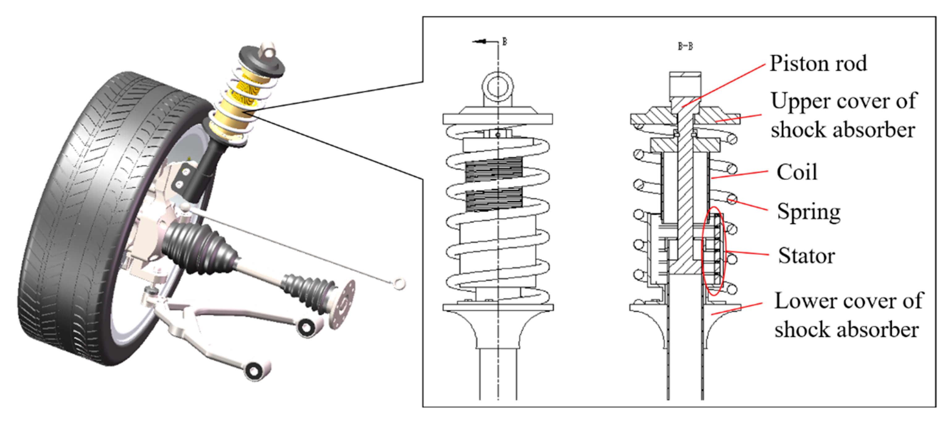
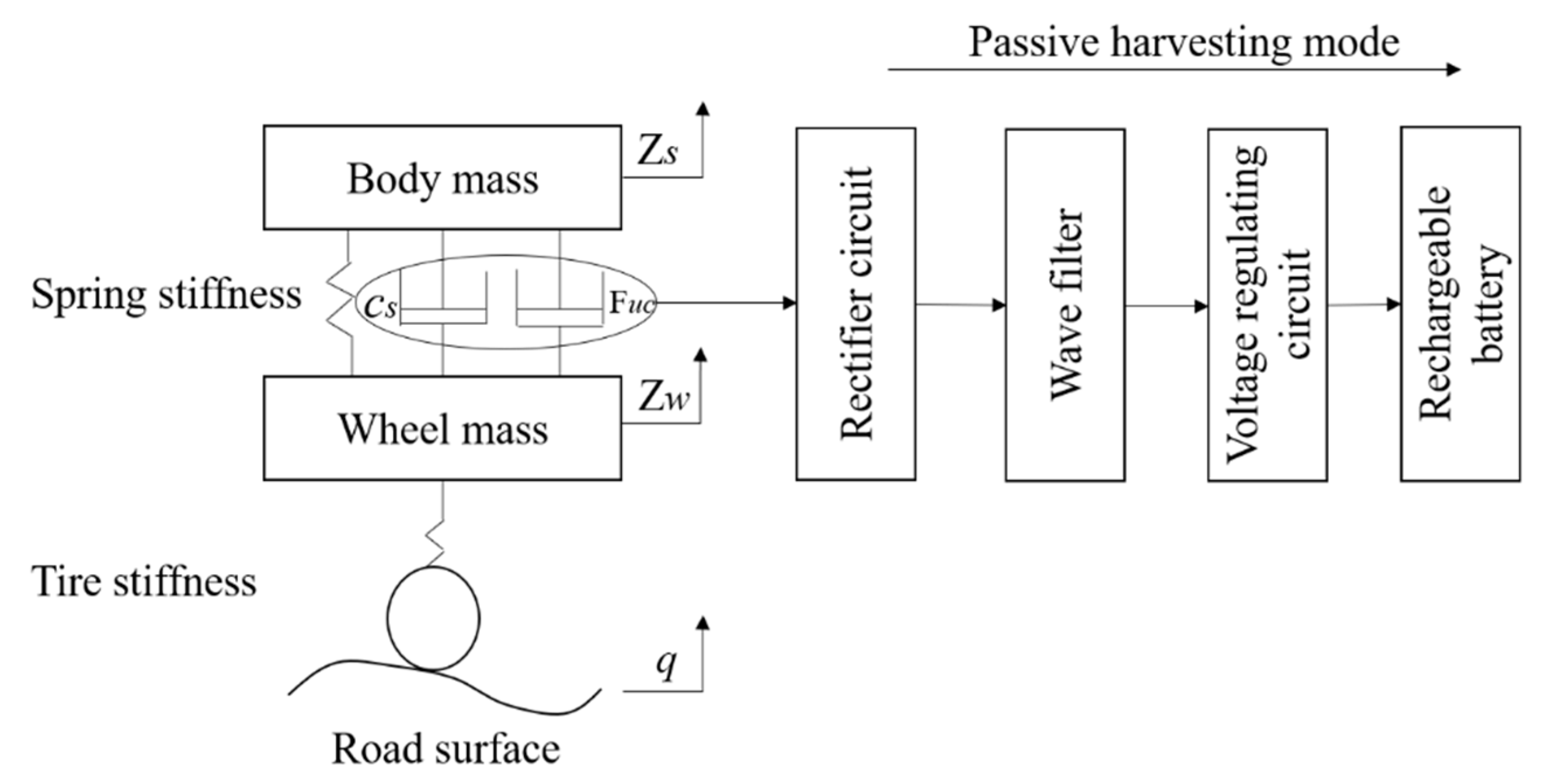
2. Structure and Working Principle of the Dual-Mode Magnetic Suspension
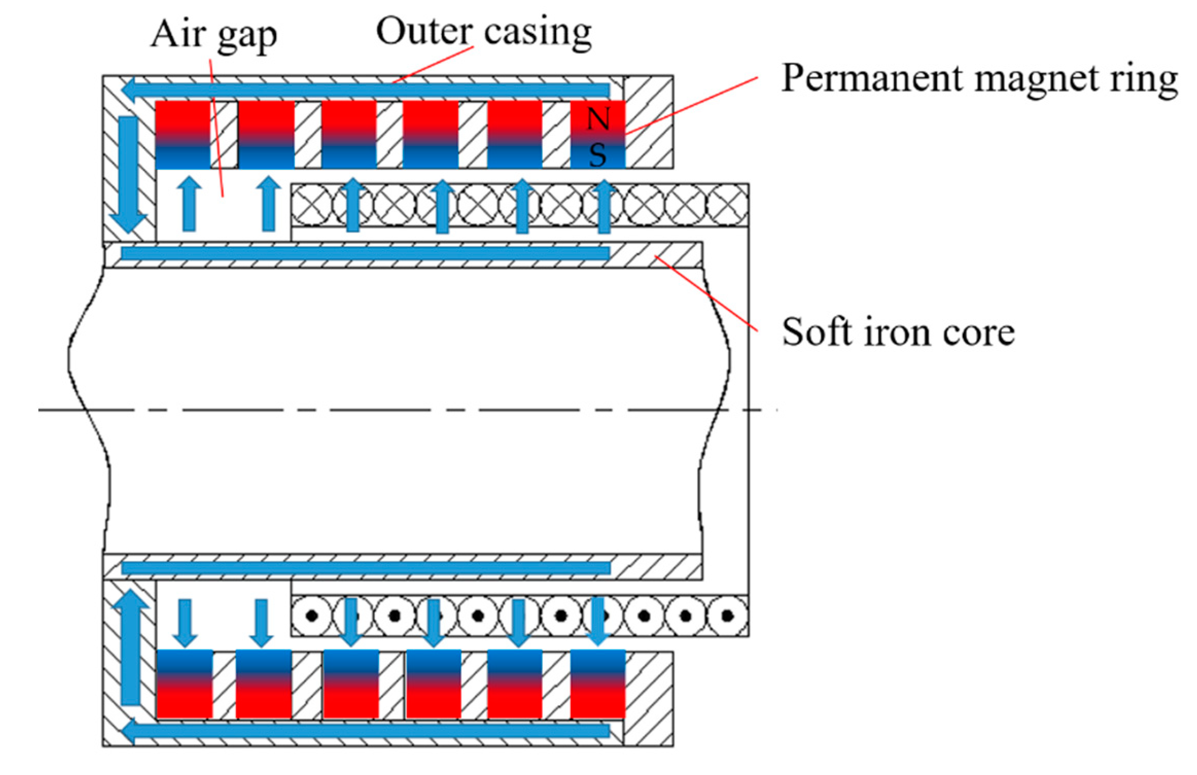
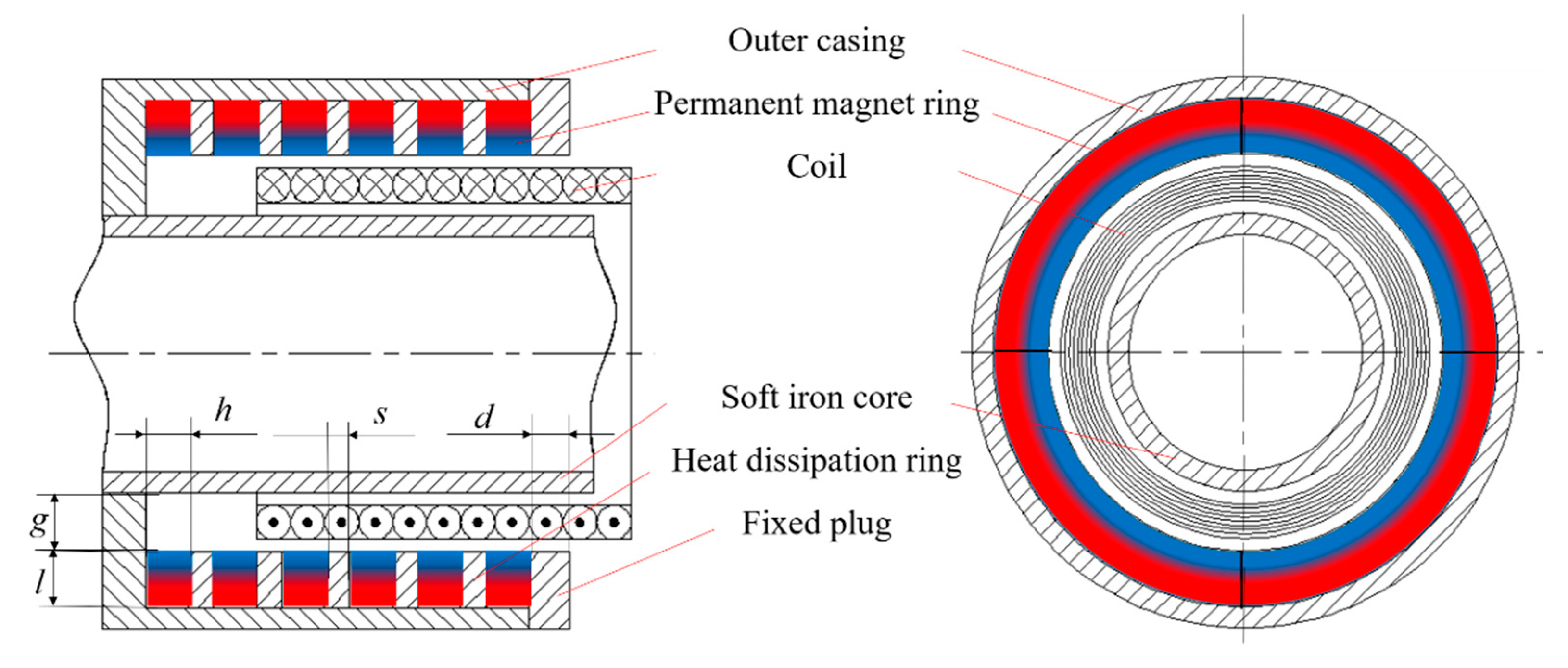
2.1. Structure

The structure of the dual-mode magnetic suspension is shown in Figure 1. The dual-mode magnetic suspension mainly consists of an actuator and a passive suspension assembly. The actuator structure is designed based on the voice coil motor structure, and the actuator includes two parts: a stator and a mover; the stator is mainly composed of the fixed plug, the permanent magnet ring, the heat dissipation ring, the soft iron core, and the outer casing. The mover part is mainly a regeneration energy coil. The actuator is installed in the air gap between the spring and the damper rod. The stator is connected to the wheel through the lower cover, and the mover is connected to the vehicle body through the upper cover. The actuator, the damper, and the spring are ensured to have concentricity during installation. The permanent magnet ring is formed by tiling-type permanent magnets, and the magnetization mode of the magnet is radial magnetization. Therefore, the permanent magnet ring, the air gap, the outer casing, and the soft iron core form the closed loop of the magnetic induction lines, as shown in Figure 2. A uniform parallel magnetic field perpendicular to the axial direction of the damper is formed in the air gap between the soft iron core and the outer casing. The permanent magnet ring and the heat dissipation ring are alternately arranged, and the plug is used to fix the permanent magnet rings and the heat dissipation rings.

2.2. Working Principle

As shown in Figure 3, when the body and the wheel move relative to each other, the relative motion of the regeneration coil and the actuator stator is generated. According to Faraday’s law of electromagnetic flux density, the coil can generate positive and negative alternating induced EMFs when it is performing the cutting magnetic induction lines motion. The rectifier circuit rectifies the induced EMF in a single direction. A filter filters out the high-frequency components in the unidirectional EMF and outputs a smoother DC EMF. After the filter process, the voltage stabilizing circuit is added, and the stable EMF is input into the rechargeable battery to realize energy regeneration. In this process, the induced current will generate the damping force that constantly blocks the relative motion of the regeneration coil and the stator of the actuator, and the actuator is equivalent to a damper.

3. Analysis of the Effects of the Stator on the Energy-Harvesting Characteristics

3.1. Effects of the Stator Parameters on the Energy-Harvesting Characteristics

When the structure parameters of the mover are constant, the effects of the stator parameters on the magnetic flux density B in the air gap of the actuator are analyzed by the simulation software.
According to the magnetic flux density model of the stator, the main parameters that affect the magnetic flux density B are the permanent magnet ring’s axial height h, the permanent magnet ring’s radial thickness l, the fixed plug’s thickness d, the heat dissipation ring’s thickness s, and the air gap g, as shown in Figure 4. Because many factors affect the magnetic flux density, to turn the problem of multiple factors into multiple single-factor problems, this paper uses the control variable method to analyze the effects of the stator parameters on the magnetic flux density.

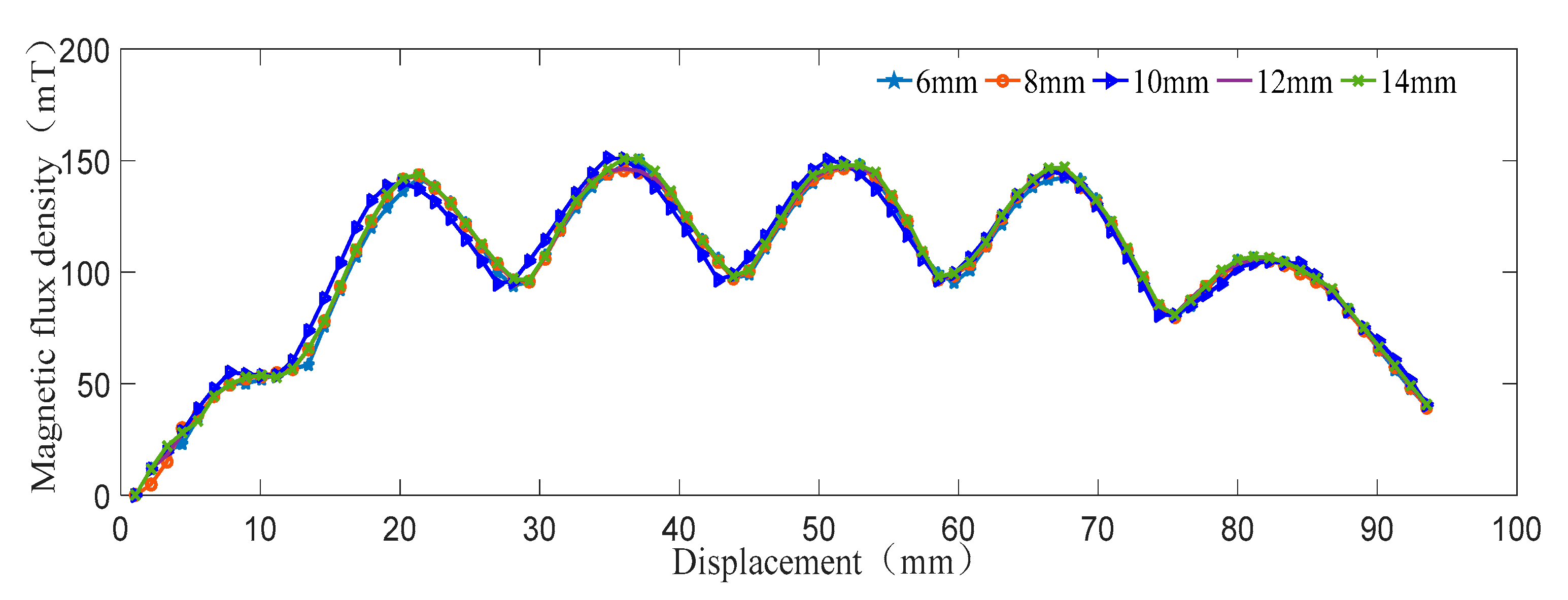
3.1.1. Effect of the Permanent Magnet Ring on the Energy Harvesting Characteristic

There are six permanent magnet rings in the actuator stator, and the magnetic flux density is strongest near the permanent magnet ring, thus, they will produce six peaks. Additionally, the material of the magnetic ring is neodymium iron boron. The investigated range of the magnetic ring radial thickness is from 6 mm to 14 mm, and the increment is 2 mm. Meanwhile, the other conditions are unchanged. The effect of the magnetic ring radial thickness on the magnetic flux density is shown in Figure 5.
According to the analysis above, the magnetic flux density trend of the five groups of magnetic rings is the same. The permanent magnet ring radial thickness is proportional to the magnetic flux density, and the magnetic flux density of the 14-mm-thick magnetic ring is the largest. The simulation range of the magnetic ring axial height is 8–14 mm, as shown in Figure 6.
It can be seen from the figure that as the magnetic ring axial height increases, the axial dimension of the actuator also changes with it. The thicker the magnetic ring is, the greater the corresponding magnetic flux density is. The 14-mm-thick magnetic ring has the maximum magnetic flux density in the air gap, while the 8-mm-thick magnetic ring has the minimum magnetic flux density in the air gap; the magnetic flux density difference between the two is 56 mT. Moreover, the volume is also the largest, and the axial height reaches 100 mm. According to the analysis of the effect of the permanent magnet ring’s axial height on the magnetic flux density, the larger the permanent magnet ring volume is, the stronger the magnetic flux density in the air gap is. Furthermore, the position of the magnetic ring in the stator is changed due to the change of the magnetic ring’s axial height, thus, the phase of the curve is changed.

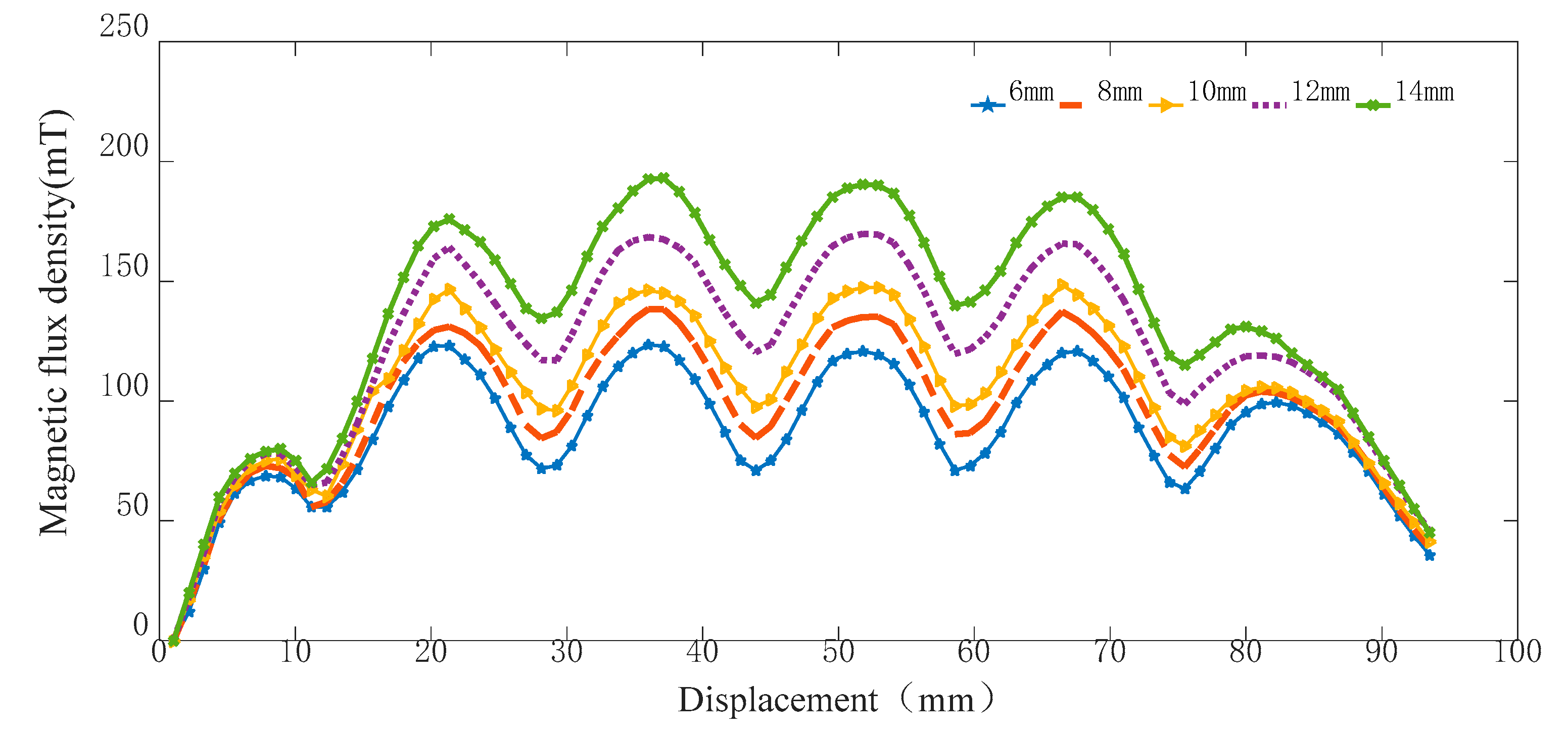
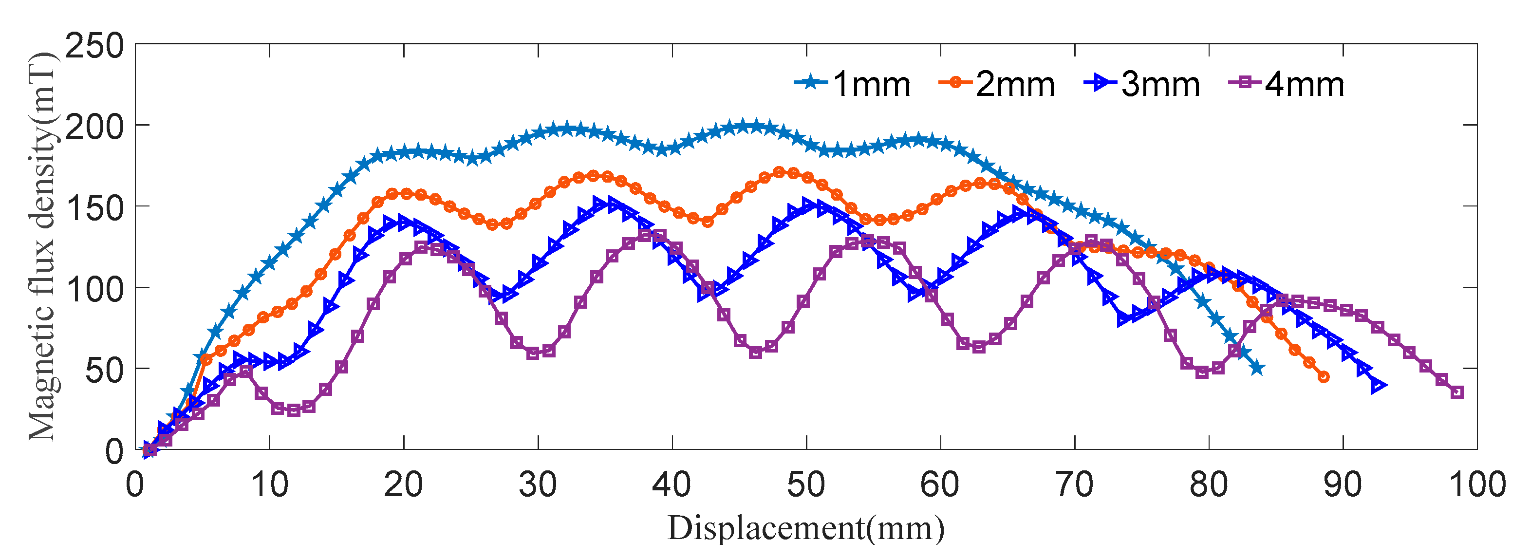
3.1.2. Effect of the Fixed Plug’s Thickness on the Energy-Harvesting Characteristic

The fixed plug’s thickness simulation range is 6–14 mm, and the value interval is 2 mm. The effect of the fixed plug’s thickness on the magnetic flux density is shown in Figure 7.
The fixed plug’s thickness is the thickness of the outer casing of the actuator stator, and the fixed plug is an essential part of the design of the actuator. The fixed plug is mainly responsible for the fixation of the permanent magnet ring and heat dissipation ring. It can be seen that when the wall thickness increases, there is no significant change in the magnetic flux density in the air gap, the magnetic flux density of 14 mm is only 0.03% higher than that of the 6 mm one. The outer magnetic fixed plug has more magnetic leakage when it is thinner, which leads to the corresponding weakening of the air gap magnetic field.

3.1.3. Effect of the Heat Dissipation Ring’s Thickness on the Energy Harvesting Characteristic

During the movement of the vehicle, the suspension shock absorber generates a lot of heat, and the heat dissipation ring is added between the magnetic rings to slow down the demagnetization phenomenon generated due to the high temperatures. The range of the heat dissipation ring’s thickness is 1–4 mm, and the value interval is 1 mm. The simulation analysis is shown in Figure 8.
As can be seen from the analysis of the figure, the heat dissipation ring thickness can produce a more significant effect on the electromagnetic force. The relative magnetic flux density and the magnetic flux density shelf space are increased with the decrease in the height of the heat dissipation ring.

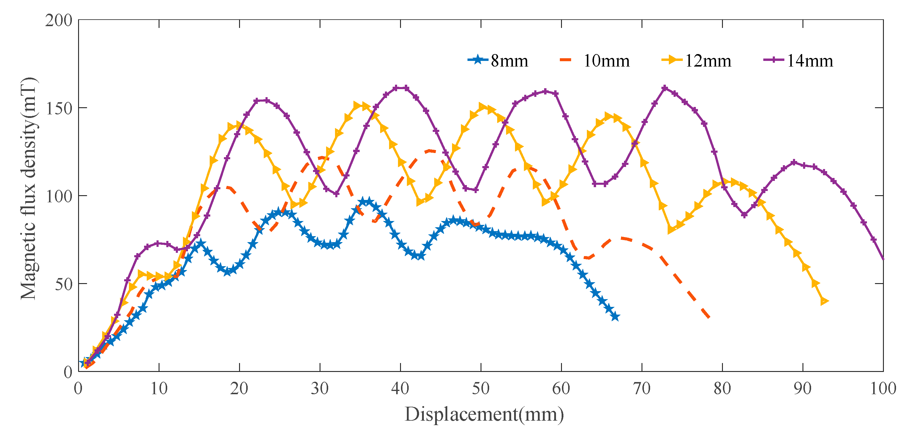
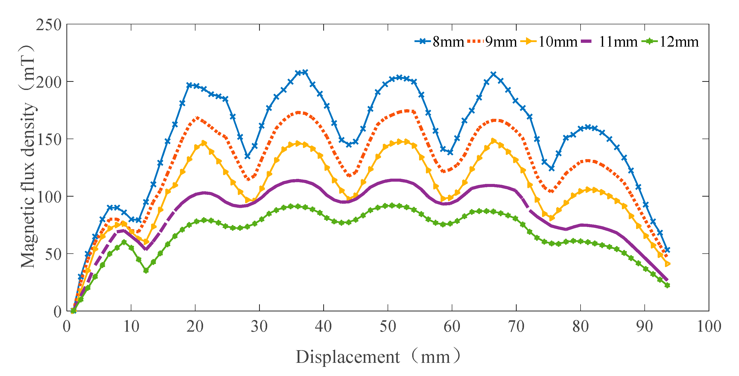
3.1.4. Effect of the Air Gap on the Energy Harvesting Characteristic

The air gap part of the actuator is the moving area of the mover coil, and the range of the investigated air gap size is 8–12 mm, and the interval is 1 mm. The simulation results are shown in Figure 9. It can be seen from the figure that the magnetic flux density shows a decreasing trend with the increase in the air gap.

3.2. Orthogonal Analysis of the Stator Parameters

3.2.1. Orthogonal Design

The orthogonal analysis has the characteristics of “uniform dispersion, neat and comparable”, and it can replace the multi-factor and multi-level test with a large workload with fewer test times, which is highly efficient and economical [25,26]. Based on the previous simulation results, this paper determines the four structural parameters of the permanent magnet ring’s radial thickness, the permanent magnet ring’s axial height, the heat dissipation ring’s thickness, and the air gap for the orthogonal experiment. The parameter ranges are 8–14 mm, 8–14 mm, 1–4 mm, and 9–12 mm, respectively. These parameters are identified in Figure 3. The orthogonal table is designed, as shown in Table 1.

3.2.2. Orthogonal Analysis

The orthogonal test scheme and the simulation results of the magnetic flux density are shown in Table 2.
The analysis results of the orthogonal test are shown in Table 3. Kjk (k = 1, 2, 3, and 4) is the sum of the simulation results with the same level k in column j. Kjpk is the average of the simulation results with the same level k in column j, and Rj is the range. It can be seen that the combination (A4 B3 D2 D1) constitutes the best parameters, and the values of the magnetic ring’s thickness, the axial height of the magnetic ring, the height of the heat dissipation ring, the air gap, and the maximum magnetic flux density strength are 14 mm, 12 mm, 3 mm, 10 mm, and 194.4 mT, respectively.
Finally, according to the above analysis, the stator parameters of the actuator are selected, as shown in Table 4.

4. Simulation Results of the Dual-Mode Magnetic Suspension

4.1. Theoretical Model of the EMF

During the relative movement between the body and the wheel, the suspension system can generate the relative motion velocity V. Therefore, the induced EMF is expressed as:
U 0 = B L V sin θ
where B is the magnetic flux density produced by the permanent magnet ring, L is the length of wire for cutting magnetic flux density wire, and θ is the angle between the velocity V or L of the damper and the magnetic flux.
L = π D c N 1
where N1 is the number of turns in the coil embedded in the magnetic flux, and Dc is the average diameter of the coil winding.
Combining Formulas (1) and (2) obtains the EMF expression:
U 0 = B π D c N 1 V sin θ
The total turns of the coil are calculated:
N 1 = L 1 ( d 2 - d 1 ) 2 d 2
where L1 is the length of the coil skeleton, d1 is the inner diameter of the coil, d2 is the outer diameter of the coil, and d is the diameter of the enameled wire.
In this paper, the sinusoidal signal is used as the road input:
X = A sin ω t
ω = 2 π f
Among these parts, A is the excitation amplitude, ω is the angular velocity, and f is frequency.
Formulas (3) and (7) vary as follows:
U 0 = B π D c N 1 V sin θ
Since the angle θ between the relative motion velocity V of the suspension and the magnetic flux density B is approximately 90°, sin θ = 1, it can be ignored; according to the Formulas (3) and (4), the induced EMF U0 and the number of turns embedded in the air gap of the coil can be known, and U0 is proportional to the motion velocity V. Therefore, the regeneration power P is proportional to the square of the number of turns N1 of the coil embedded in the air gap and the square of the velocity V of motion. When a sinusoidal signal is used as the road surface input, according to the Formula (7), the EMF is related to the three variables of the number of turns, the frequency, and the amplitude.

4.2. Simulation Analysis of the EMF

According to the theoretical model of the dual-mode magnetic suspension, the parameters affecting the energy-harvesting characteristics of the suspension include the vibration frequency, the amplitude, and the turns of the regeneration coil. The EMF is simulated by the control variable method. The simulated coil parameters are shown in Table 5.

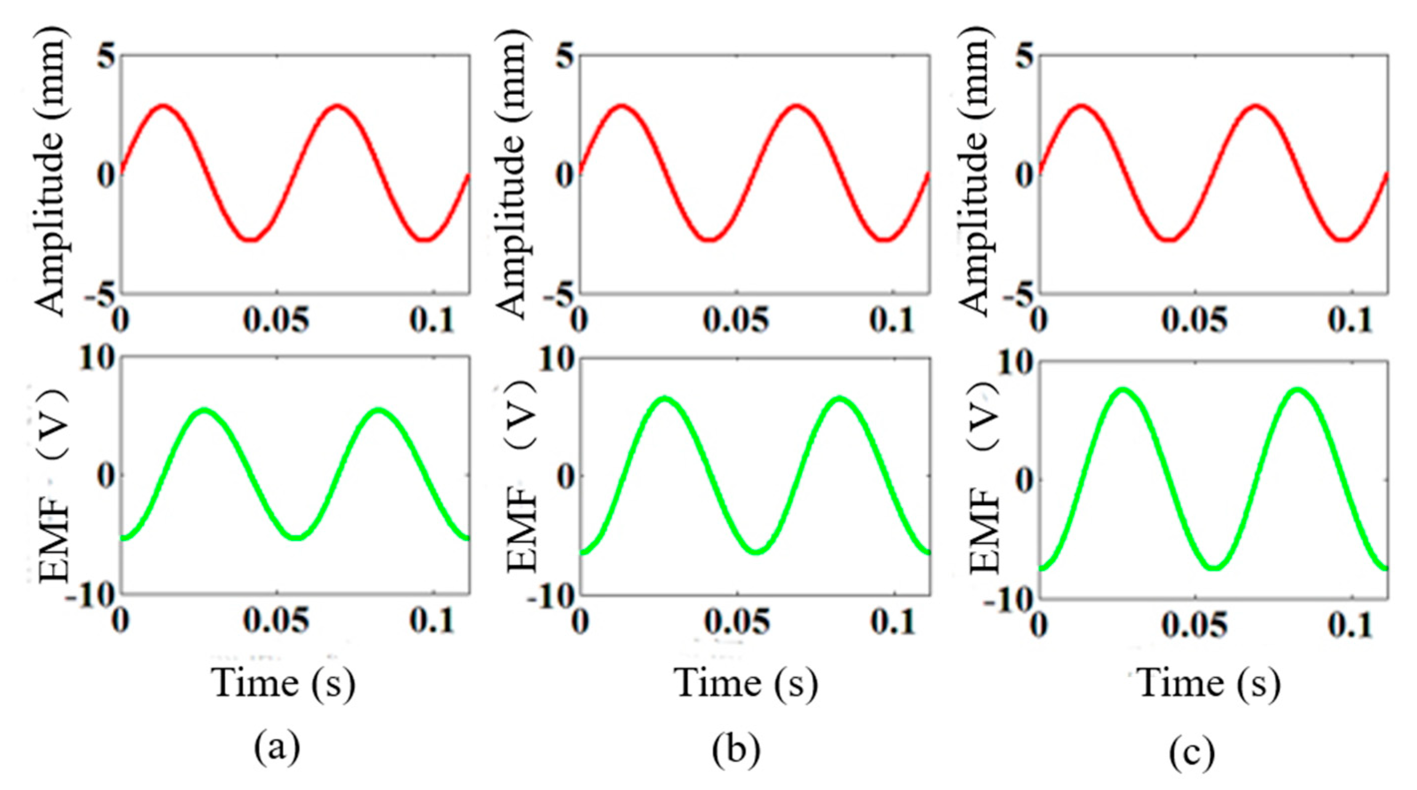
4.2.1. Effect of the Number of Coil Turns on the EMF

The turns of the coil entering the stator air gap are positively correlated with the position depth of the coil entering the air gap. The studied depth values of the coil entering the air gap include 50 mm, 60 mm, and 70 mm (the number of coil turns are 188, 1130, and 1319, respectively). The input and output simulation results are shown in Figure 10, and the simulation time is 0.1 s. (From left to right, they are 50 mm, 60 mm, and 70 mm, respectively.)
The simulation results of the induced EMF are 4.7 V, 6.7 V, and 8.3 V in turn, which are increased by 42.5% and 23.8%, respectively. Thus, the frequency and amplitude remain unchanged, and the coil is embedded deeper into the air gap, which leads to the increase in the induced EMF.

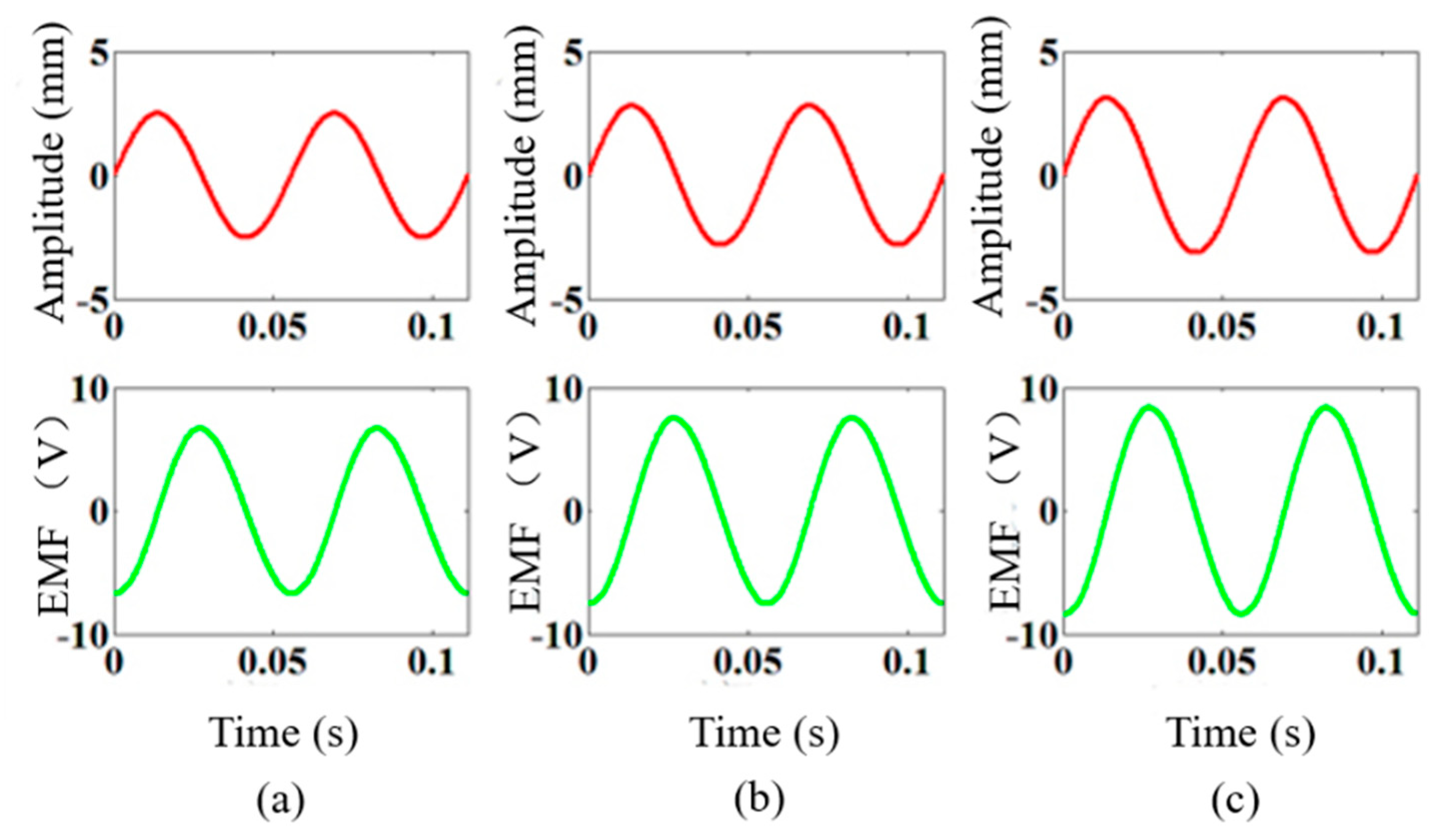
4.2.2. Effect of the Excitation Amplitude on the EMF

The simulation results of the input and output of the coil at 70 mm in the excitation frequency 18 Hz are calculated. The studied excitation amplitudes included 2.5 mm, 2.8 mm, and 3.1 mm, and the simulation time is 0.1 s. (The excitation amplitudes from left to right are 2.5 mm, 2.8 mm, and 3.1 mm, respectively, as shown in Figure 11.)
The simulation results of the induced EMF are 6.4 V, 8.0 V, and 9.2 V, which are increased by 25.0% and 15.1%, respectively. Therefore, the number of turns and frequency remain unchanged, and as the vibration amplitude increases, the induced EMF becomes larger in the sequence.

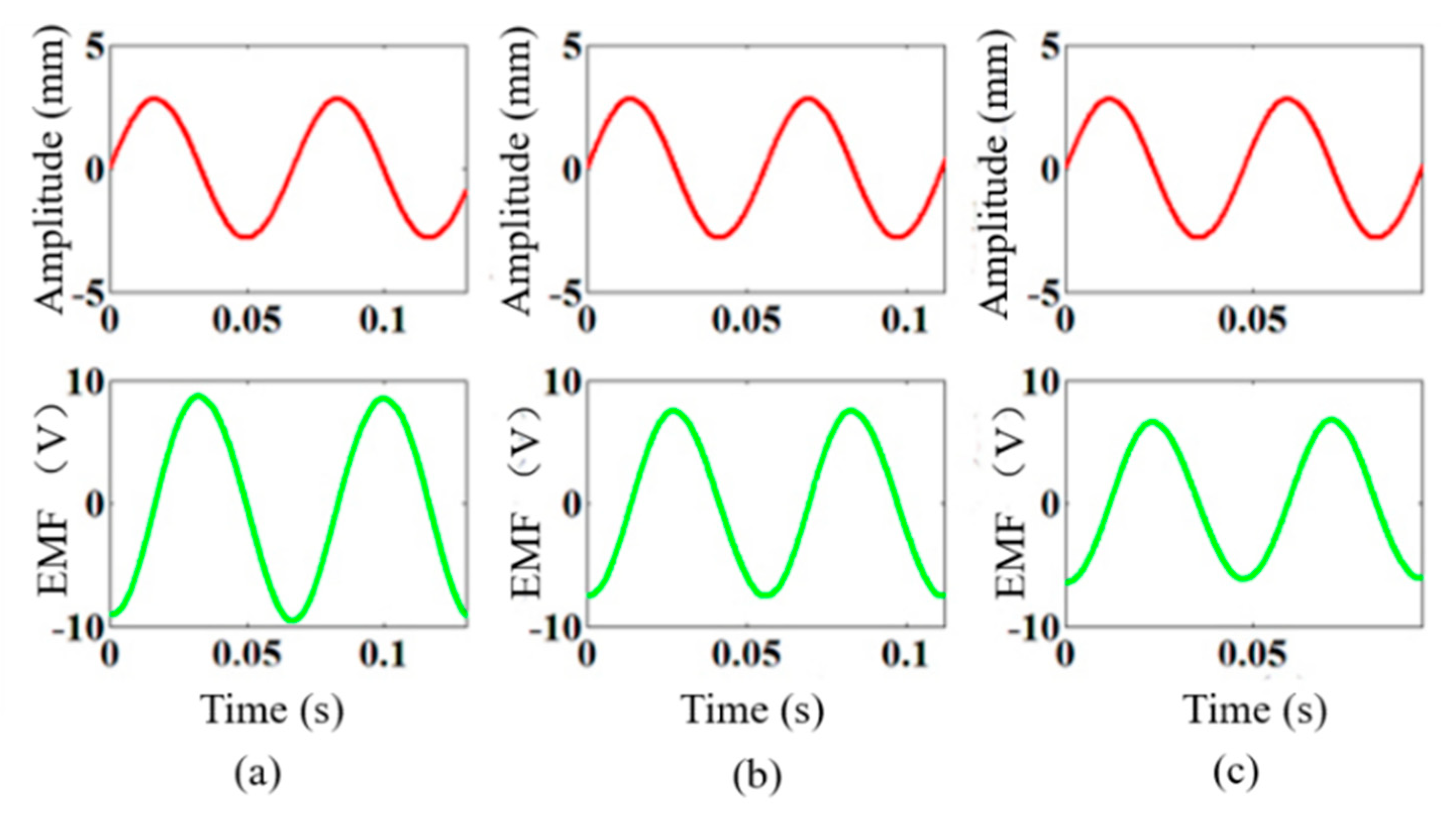
4.2.3. Effect of the Excitation Frequency on the EMF

When the position of the coil entering the air gap is 70 mm and the excitation amplitude is 2.8 mm, the effect of the excitation frequency on the EMF is analyzed. The input and output simulation results are shown in the excitation frequencies of 15 Hz, 18 Hz, and 21 Hz, and the simulation time is 0.1 s. (The excitation frequencies from left to right are 15 Hz, 18 Hz, and 21 Hz, respectively, as shown in Figure 12.)
The simulation results of the induced EMF are 7.3 V, 8.4 V, and 7.5 V in sequence, which are first increased by 15.1%, and then, they are decreased by 10.7%. When the turns and amplitude remain unchanged, the EMF is increased more as the frequency is increased.

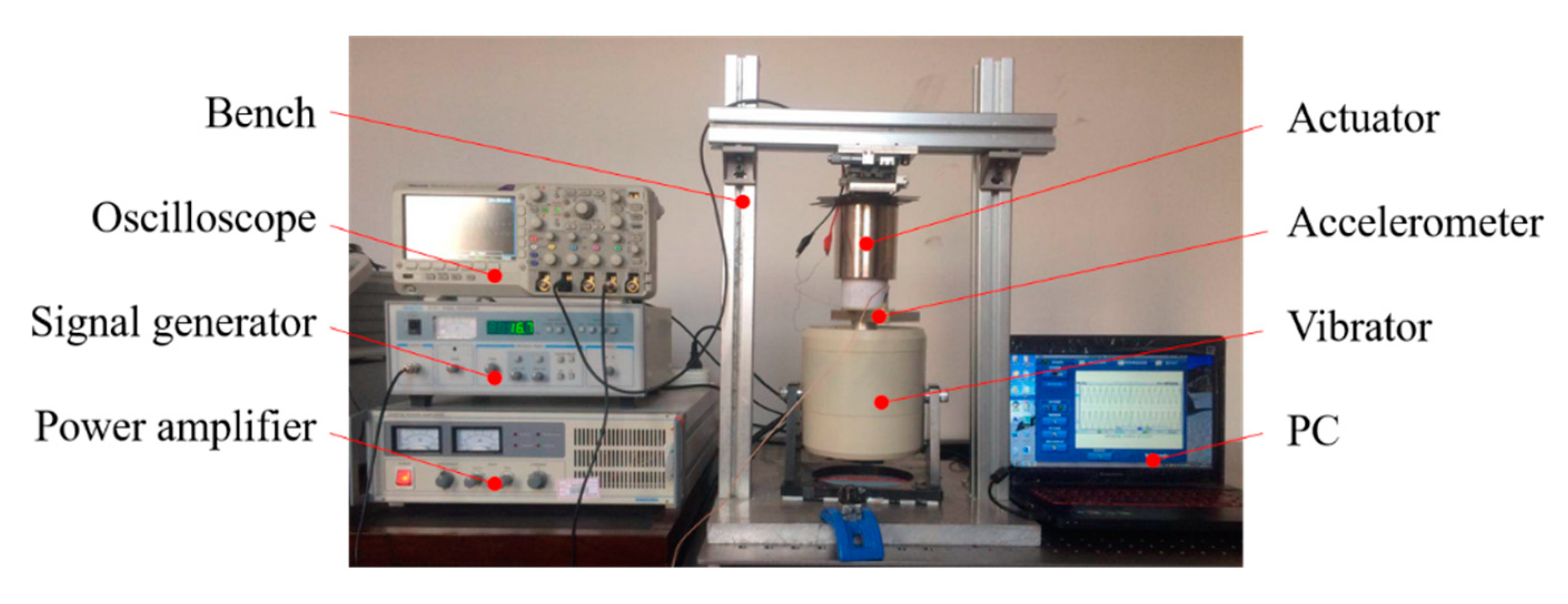
5. Experiment Verification

5.1. Experimental Setup

In order to verify the correctness of the theoretical model and the simulation analysis for the dual-mode magnetic suspension, a prototype experimental system is built. The actuator is the core component of the dual-mode magnetic suspension, and the sinusoidal signal generated by the exciter is used as the road input to verify the energy-harvesting characteristics of the actuator. The specific signal excitation process is one by which the function signal generator generates a sinusoidal signal through the power amplifier to reach the vibrator. Finally, the vibrator can generate sinusoidal excitation. The Tektronix oscilloscope is used to gather the acceleration and electromotive signals, and the computer receives the synchronization signal through OpenChoice Desktop software (Version: V2.8; Creator: Tektronix; Location: Shenyang, China). The specific experimental setup is shown in Figure 13.
According to the theoretical model, the effects of the turn, the amplitude, and the frequency on the energy-harvesting characteristics are verified. The input is the excitation signal, and the output is the EMF.

5.2. Experimental Results

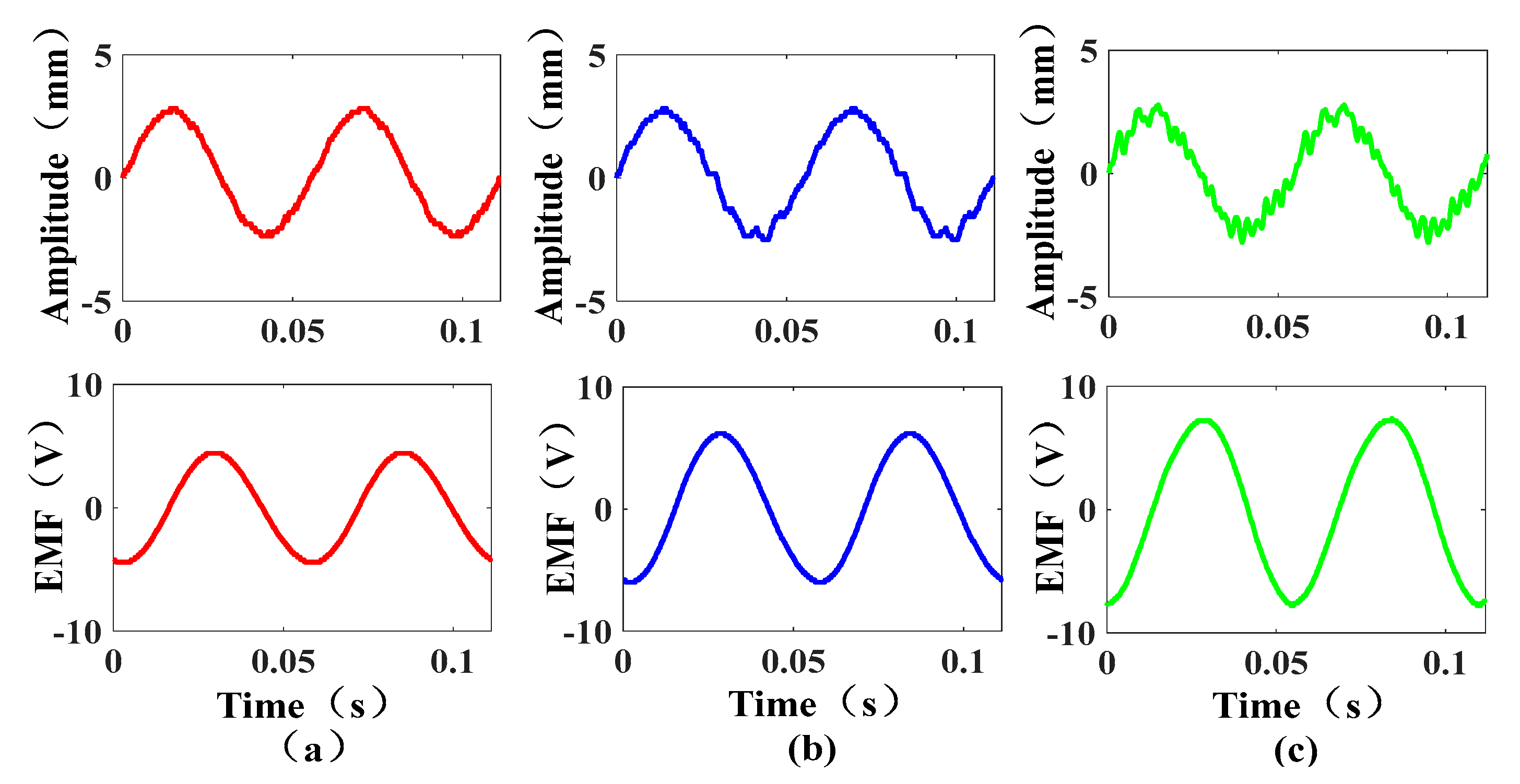
5.2.1. Experimental Results for the Effect of the Number of Coil Turns on the EMF

Because the turns embedded in the air gap of the actuator can be expressed by the position depth of the coil entering the air gap, the effect of the turns on the energy-harvesting characteristics is verified when the coil is in different positions. When the excitation frequency is 18 Hz, the peak input amplitude is 2.8 mm, and the distance between the coil and the air gap from left to right is 50 mm, 60 mm, and 70 mm (the number of coil turns are 188, 1130, and 1319, respectively); the input and output results are shown in Figure 14.
According to the experimental results, the peak values of the output EMF are 4.4 V, 6.2 V, and 7.7 V from left to right, which are increased by 40.9% and 24.1%, respectively. Comparing the peaks of the EMF in the three cases, it can be obtained that when the amplitude and frequency are unchanged, the peak value of the induced EMF is greater with the increase in the number of coil turns.

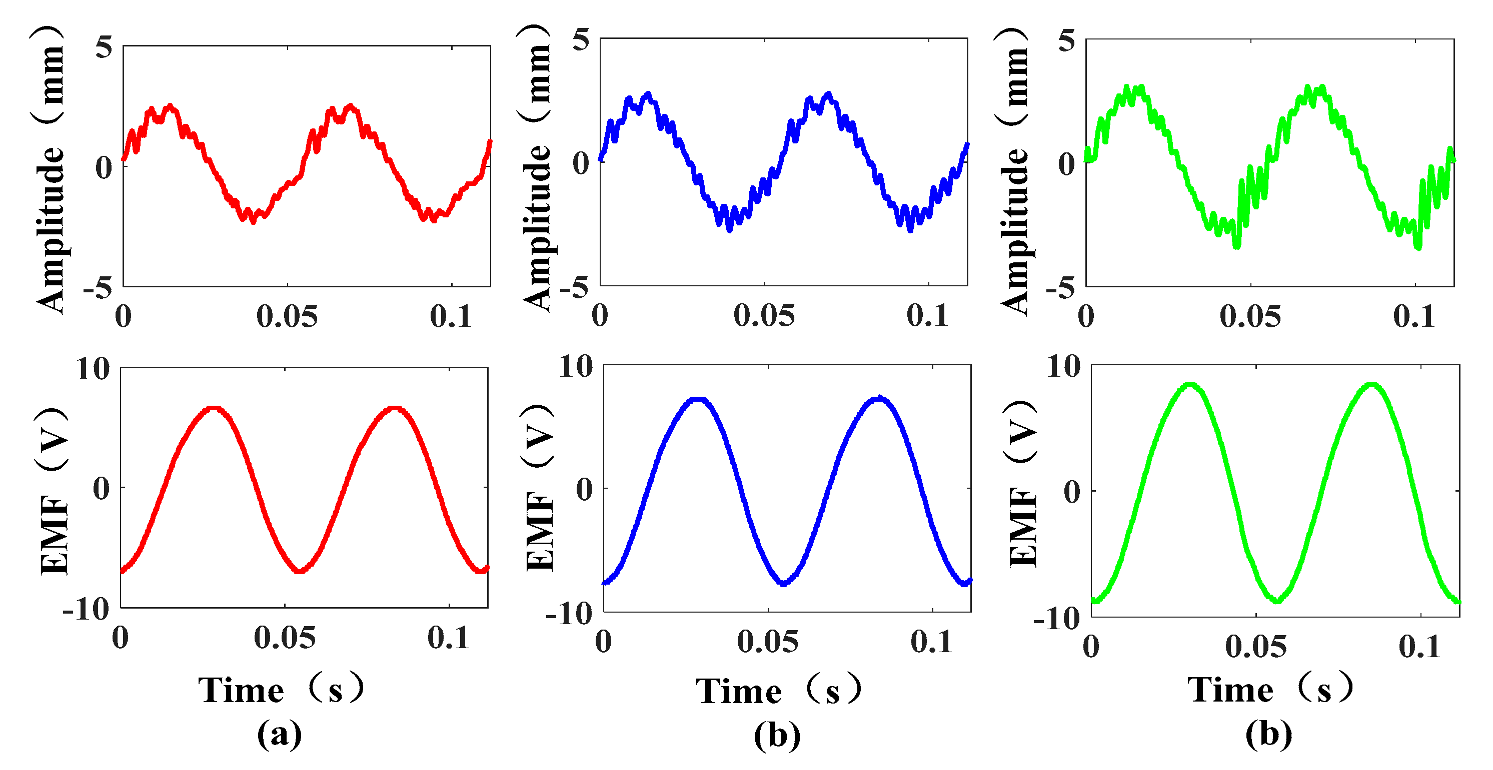
5.2.2. Experimental Results for the Effect of the Excitation Amplitude on the EMF

When the excitation frequency is 18 Hz, the distance between the coil and the air gap is 70 mm, and the input amplitudes from left to right are 2.5 mm, 2.8 mm, and 3.1 mm, respectively; the input and output results are shown in Figure 15.
According to the experimental results, the peak values of the output EMF from left to right are 6.6 V, 7.8 V, and 8.8 V, which are increased by 18.1% and 12.8%, respectively. Comparing the EMF of the different input amplitudes, it can be obtained that when the number of turns and frequency are unchanged, the peak value of the induced EMF is increased as the excitation amplitude is increased.

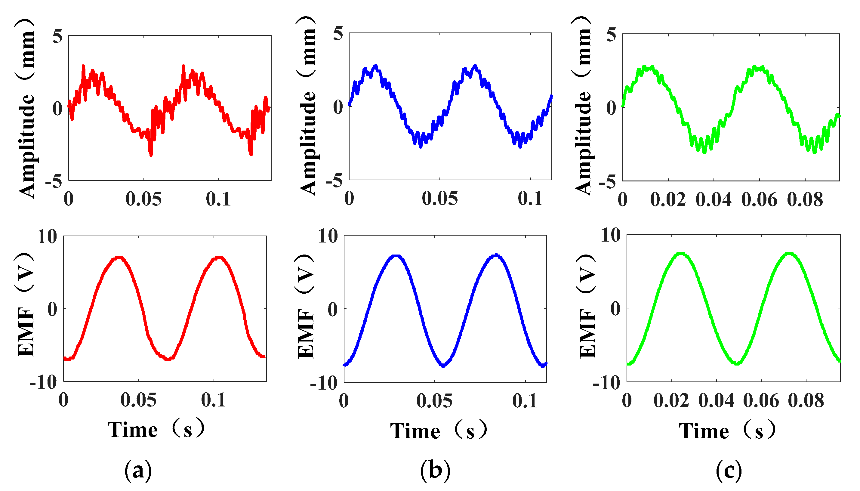
5.2.3. Experimental Results of the Effect of the Excitation Frequency on the EMF

When the excitation amplitude is 2.8 mm, the distance between the coils and the air gap is 70 mm, and the frequencies from left to right are 15 Hz, 18 Hz, and 21 Hz, respectively; the input and output results are shown in Figure 16.
According to the experimental results, the peak values of the output EMF are 7 V, 7.8 V, and 7.6 V, respectively. The experimental results show that when the turns and the excitation amplitude remain unchanged with the increase in the frequency, the EMF tends to increase first, and then, they decrease. The main reason is that when the excitation frequency is equal to the resonance frequency of the system, the output EMF is at its maximum.
Comparing the simulation results and the experimental results of the effect of three parameters on the EMF, the simulation results are consistent with the experimental results. In the case where the other variables are consistent, the effect of the number of coil turns and the amplitude on the energy-harvesting characteristics is much greater than the effect of the excitation frequency on the energy-harvesting characteristics. More turns and a greater amplitude can lead to a greater induced EMF.

6. Conclusions

This paper proposes a dual-mode magnetic suspension with energy harvesting and active control. The suspension is stable and safe, and it can complete the conversion of vibration and energy without a complicated conversion mechanism. The optimal structural parameters of the actuator are determined through the finite element simulation analysis, and the experimental prototype is built. Furthermore, the control variable method is used to analyze the effect of the turns of the embedded magnetic field coil and the amplitude and frequency of the excitation signal on the energy-harvesting characteristics of the dual-mode magnetic suspension. Based on the numerical and experimental results, the following conclusions can be obtained:
(1)
The number of coil turns have the most significant effect on the energy-harvesting characteristics, with a rate of change up to 40.9%, which is followed by the amplitude of the excitation signal, up to 18.1%, and finally, the frequency of the excitation signal.
(2)
With the increase in the number of coil turns and the excitation amplitude, the output-induced EMF of the suspension is increased.
(3)
When the excitation frequency is equal to the resonance frequency, the vehicle body resonates with the excitation signal, and the induced EMF is large. Additionally, when the coil enters the air gap of 70 mm (the number of coil turns is 1319), the excitation amplitude is 3.1 mm, and the frequency is 18 Hz, the maximum induced EMF is 8.8 V.
This paper shows the potential good energy regeneration value of this regeneration suspension. In future work, the energy harvesting and dynamic performance of the real vehicle with the dual-mode magnetic suspension will be investigated.

Author Contributions

Conceptualization, W.J. and X.Z.; methodology, W.J., Y.S., F.S. and X.Z.; software, W.J. and Y.X.; validation, W.J., R.Z., F.S. and X.Z.; investigation, W.J. and Y.S.; data curation, X.Z. and Y.X.; writing—original draft preparation, W.J.; writing—review and editing, X.Z., Y.S. and R.Z.; supervision, F.S. and X.Z.; funding acquisition, F.S. and X.Z. All authors have read and agreed to the published version of the manuscript.

Funding

This research was funded by the National Natural Science Fund of China (No. 52005345, No. 52005344), the National Key Research and Development Project (No. 2020YFC2006701), the Scientific Research Fund Project of Liaoning Provincial Department of Education (No. LJGD2020002), and the Major Project of the Ministry of Science and Technology of Liaoning Province (No. 2022JH1/10400027).

Institutional Review Board Statement

Not applicable.

Informed Consent Statement

Not applicable.

Data Availability Statement

Not applicable.

Conflicts of Interest

The authors declare no conflict of interest.

References

  1. Long, G.M.; Ding, F.; Zhang, N.; Zhang, J.; Qin, A. Regenerative active suspension system with residual energy for in-wheel motor driven electric vehicle. Appl. Energy 2020, 260, 114180. [Google Scholar] [CrossRef]
  2. Gu, C.; Yin, J.; Luo, J.; Chen, X.B.; Wang, J.M. Performance-oriented controls of a novel rocker-pushrod electromagnetic active vehicle suspension. Mech. Syst. Signal Process. 2018, 109, 1–14. [Google Scholar] [CrossRef]
  3. Zou, J.Y.; Guo, X.X.; Abdelkareem, M.A.A.; Xu, L.; Zhang, J. Modelling and ride analysis of a hydraulic interconnected suspension based on the hydraulic energy regenerative shock absorbers. Mech. Syst. Signal Process. 2019, 127, 345–369. [Google Scholar] [CrossRef]
  4. Zheng, P.; Gao, J.W. Damping force and energy recovery analysis of regenerative hydraulic electric suspension system under road excitation: Modelling and numerical simulation. Math. Biosci. Eng. 2019, 16, 6298–6318. [Google Scholar] [CrossRef]
  5. Li, S.Y.; Xu, J.; Pu, X.H.; Tao, T.; Gao, H.N.; Mei, X.S. Energy-harvesting variable/constant damping suspension system with motor based electromagnetic damper. Energy 2019, 189, 116199. [Google Scholar] [CrossRef]
  6. Wei, W.; Sun, F.; Jin, J.Q.; Zhao, Z.Y.; Miao, L.G.; Li, Q.; Zhang, X.Y. Proposal of energy-recycle type active suspension using magnetic force. Int. J. Appl. Electromagn. Mech. 2019, 59, 577–585. [Google Scholar] [CrossRef]
  7. Khoshnoud, F.; Zhang, Y.C.; Shimura, R.; Shahba, A.; Jin, G.M.; Pissanidis, G.; Chen, Y.K.; De Silva, C.W. Energy regeneration from suspension dynamic modes and self-powered actuation. IEEE/ASME Trans. Mechatron. 2015, 20, 2513–2524. [Google Scholar] [CrossRef] [Green Version]
  8. Nakano, K.; Suda, Y.; Nakadai, S. Self-powered active vibration control using a single electric actuator. J. Sound Vib. 2003, 260, 213–235. [Google Scholar] [CrossRef]
  9. Zhang, J.M.; Liu, J.; Liu, B.L.; Li, M. Fractional order PID control based on ball screw energy regenerative active suspension. Actuators 2022, 11, 189. [Google Scholar] [CrossRef]
  10. Florean-Aquino, K.H.; Arias-Montiel, M.; Linares-Flores, J.; Mendoza-Larios, J.G.; Cabrera-Amado, A. Modern semi-active control schemes for a suspension with MR actuator for vibration attenuation. Actuators 2022, 10, 22. [Google Scholar] [CrossRef]
  11. Yang, X.F.; Zhao, W.T.; Liu, Y.L.; Chen, L.; Meng, X.P. Design and experimental study of the energy-regenerative circuit of a hybrid vehicle suspension. Sci. Prog. 2020, 103, 0036850419874999. [Google Scholar] [CrossRef] [Green Version]
  12. Kim, J.H.; Shin, Y.J.; Chun, Y.D.; Kim, J.H. Design of 100W regenerative vehicle suspension to harvest energy from road surfaces. Int. J. Precis. Eng. Manuf. 2018, 19, 1089–1096. [Google Scholar] [CrossRef]
  13. Arroyo, E.; Badel, A.; Formosa, F. Energy harvesting from ambient vibrations: Electromagnetic device and synchronous extraction circuit. J. Intell. Mater. Syst. Struct. 2013, 24, 2023–2035. [Google Scholar] [CrossRef]
  14. Sapinski, B. Energy-harvesting linear MR damper: Prototyping and testing. Smart Mater. Struct. 2014, 23, 035021. [Google Scholar] [CrossRef]
  15. Sapinski, B.; Rosol, M.; Wegrzynowski, M. Investigation of an energy harvesting MR damper in a vibration control system. Smart Mater. Struct. 2016, 25, 125017. [Google Scholar] [CrossRef]
  16. Zhu, X.; Deng, L.; Sun, S.; Yan, T.; Yu, J.; Ma, Z.; Li, W. Development of a variable stiffness magnetorheological damper with self-powered generation capability. J. Intell. Mater. Syst. Struct. 2020, 31, 209–219. [Google Scholar] [CrossRef] [Green Version]
  17. Firoozy, P.; Ebrahimi-Nejad, S. Broadband energy harvesting from time-delayed nonlinear oscillations of magnetic levitation. J. Intell. Mater. Syst. Struct. 2020, 31, 737–755. [Google Scholar] [CrossRef]
  18. Zou, J.Y.; Guo, X.X.; Xu, L.; Tan, G.F.; Zhang, C.C.; Zhang, J. Design, modeling, and analysis of a novel hydraulic energy-regenerative shock absorber for vehicle suspension. Shock Vib. 2017, 2017, 3186584. [Google Scholar] [CrossRef] [Green Version]
  19. Wei, W.; Li, Q.; Xu, F.; Zhang, X.; Jin, J.; Jin, J.; Sun, F. Research on an electromagnetic actuator for vibration suppression and energy regeneration. Actuators 2020, 9, 42. [Google Scholar] [CrossRef]
  20. Beltran-Carbajal, F.; Valderrabano-Gonzalez, A.; Favela-Contreras, A.; Hernandez-Avila, J.L.; Lopez-Garcia, I.; Tapia-Olvera, R. An active vehicle suspension control approach with electromagnetic and hydraulic actuators. Actuators 2019, 8, 35. [Google Scholar] [CrossRef]
  21. Wu, H.C.; Zhou, J.; Xie, C.H.; Zhang, J.Y.; Huang, Y.M. Two-dimensional time series sample entropy algorithm: Applications to rotor axis orbit feature identification. Mech. Syst. Signal Process. 2021, 147, 107123. [Google Scholar]
  22. Zhou, J.; Wu, H.C.; Wang, W.Y.; Yang, K.Z.; Hu, Y.F.; Guo, X.H.; Song, C.S. Online unbalance compensation of a maglev rotor with two active magnetic bearings based on the LMS algorithm and the influence coefficient method. Mech. Syst. Signal Process. 2022, 166, 108460. [Google Scholar]
  23. Zhou, R.; Yan, M.; Sun, F.; Jin, J.; Li, Q.; Xu, F.; Zhang, M.; Zhang, X.; Nakano, K. Experimental validations of a magnetic energy-harvesting suspension and its potential application for self-powered sensing. Energy 2022, 239, 122205. [Google Scholar] [CrossRef]
  24. Zhou, R.; Sun, F.; Yan, M.; Jin, J.; Li, Q.; Xu, F.; Zhang, X.; Nakano, K. Design, analysis and prototyping of a magnetic energy-harvesting suspension for vehicles. Smart Mater. Struct. 2020, 29, 105034. [Google Scholar] [CrossRef]
  25. Li, Q.; Peng, Z.; Jiang, W.; Ouyang, L.; Wang, H.; Liu, J.; Zhu, M. Optimization of Ti-Zr-Cr-Fe alloys for 45 MPa metal hydride hydrogen compressors using orthogonal analysis. J. Alloys Compd. 2021, 889, 161629. [Google Scholar] [CrossRef]
  26. Xie, C.; Zhang, T.; Yuan, Z.; Feng, A.; Wu, L. Optimization design and internal flow analysis of prefabricated barrel in centrifugal prefabricated pumping station with double pumps. Processes 2022, 10, 1877. [Google Scholar] [CrossRef]
Figure 1. Structure of the dual-mode magnetic suspension.
Actuators 11 00363 g001
Figure 2. Magnetic circuit in the actuator stator.
Actuators 11 00363 g002
Figure 3. Working principle.
Actuators 11 00363 g003
Figure 4. The inner structure of the actuator.
Actuators 11 00363 g004
Figure 5. Effect of the magnetic ring radial thickness on the magnetic flux density.
Actuators 11 00363 g005
Figure 6. Effect of the magnetic ring axial height on the magnetic flux density.
Actuators 11 00363 g006
Figure 7. Effect of the fixed plug’s thickness on the magnetic flux density.
Actuators 11 00363 g007
Figure 8. Effect of the heat dissipation ring’s thickness on the magnetic flux density.
Actuators 11 00363 g008
Figure 9. Effect of the air gap on the magnetic flux intensity.
Actuators 11 00363 g009
Figure 10. Effect of the number of coil turns on the EMF: (a) 188; (b) 1130; (c) 1319.
Actuators 11 00363 g010
Figure 11. Effect of the excitation amplitude on the EMF: (a) 2.5 mm; (b) 2.8 mm; (c) 3.1 mm.
Actuators 11 00363 g011
Figure 12. Effect of the excitation frequency on the EMF: (a) 15 Hz; (b) 18 Hz; (c) 21 Hz.
Actuators 11 00363 g012
Figure 13. Vibration experimental setup.
Actuators 11 00363 g013
Figure 14. Effect of the number of coil turns on the EMF: (a) 188; (b) 1130; (c) 1319.
Actuators 11 00363 g014
Figure 15. Effect of the excitation amplitude on the EMF: (a) 2.5 mm; (b) 2.8 mm; (c) 3.1 mm.
Actuators 11 00363 g015
Figure 16. Effect of the excitation frequency on the EMF: (a) 15 Hz; (b) 18 Hz; (c) 21Hz.
Actuators 11 00363 g016
Table 1. Orthogonal design table of level factors.
LevelMagnetic Ring Radial Thickness (mm)
A
Magnetic Ring Axial Height (mm)
B
Heat Dissipation Ring Thickness (mm)
C
Air Gap (mm)
D
18819
21010210
31212311
41414412
Table 2. Orthogonal test scheme and simulation results.
NumberingMagnetic Ring Radial Thickness
(mm)
Magnetic Ring Axial Height (mm)Heat Dissipation Ring Thickness
(mm)
Air Gap
(N)
Magnetic Flux Density
(mT)
11111163.625
21222165.926
31333169.317
41444176.305
52123178.128
62214186.419
72332184.526
82441188.513
93134183.614
103243186.325
113112188.146
123421190.182
134342189.379
144234192.353
154321194.476
164413186.479
Table 3. Orthogonal analysis.
NameMagnetic Ring Radial Thickness (mm)
A
Magnetic Ring Axial Height (mm)
B
Heat Dissipation Ring Thickness (mm)
C
Air Gap (mm)
D
Kj1675.173713.112724.669734.373
Kj2747.412731.023718.726737.927
Kj3748.268737.698739.760720.249
Kj4752.736741.479740.522730.864
Kjp1168.775178.278181.167183.668
Kjp2186.853189.756179.691184.482
Kjp3187.067184.424184.940180.062
Kjp4188.184185.370185.130182.716
Rj19.40911.4785.4393.606
Influencing factorsA > B > C > D
Best levelA4B3C2D1
Best combinationA4 B3 C2 D1
Table 4. Stator parameters of the actuator.
DescriptionSymbolNumerical Value
Permanent magnet ring length/mmh10
Permanent magnet ring height/mml12.5
Cooling ring height/mms3
Outer fixed plug wall thickness/mmd10
Air gap length/mmXg90
Air gap width/mmYg10
NdFeB N42H remanence/TBr1.18
NdFeB N42H coercivity/A/mHc−880,000
Air permeability/H/mμ04 π × 10−7
Table 5. Parameters of the simulated coil.
DescriptionRepresentation SymbolNumerical Value
Average diameter of the windingDc0.0635 m
Resistivity of copperρ1.75 × 10⁻⁸ Ω·m
Coil skeleton lengthL0.09 m
Coil resistanceR62 Ω
Magnetic flux densityB0.09 T
Coil turns in the air gapN11696
Publisher’s Note: MDPI stays neutral with regard to jurisdictional claims in published maps and institutional affiliations.

