Abstract
Electrical discharge machining (EDM) is not limited to the strength and hardness of conductive materials, and is a non-contact special processing technology. In micro-EDM, there are problems such as untimely axial positioning, unstable inter-electrode machining voltage, and difficulty in discharging inter-electrode electric erosion products. This paper considers a magnetic actuator with fast response and high accuracy as the local actuator for a micro-EDM. By introducing a domain adjustment mechanism, a variable domain fuzzy PID controller was designed to control the inter-electrode voltage control system of the magnetic actuator for micro-EDM using an intelligent control strategy. During the micro-EDM machining process, the controlled magnetic actuator drives the tool electrode in the axial direction for rapid micro-positioning, thus maintaining effective inter-electrode machining voltage and achieving a high-speed and high precision EDM. Simulation and experimental results showed that compared with traditional micro-EDM, the machining efficiency of the variable domain fuzzy PID control magnetic actuator, and traditional micro-EDM cooperative control, was increased by 40%, the machining process was more stable, and the quality of the machined surface was better.
1. Introduction
Electrical discharge machining (EDM) is a special machining method that immerses the workpiece in the working medium and conducts electrical erosion on conductive materials through non-contact pulse spark discharge between the tool electrode and the workpiece [1]. In the process of EDM, the two stages of the pulse power supply are connected with the tool electrode and the metal workpiece to provide the required pulse voltage, and the pulse discharge is used to break down the working medium and form a discharge channel. Since the pulse discharge time is in the order of microseconds, the discharge channel is narrow, and the energy at the discharge position is highly concentrated, resulting in instantaneous high temperature, which leads to the melting of metal materials. Different from traditional cutting methods, EDM has no macro cutting force, which is especially convenient for processing complex cavities, and materials with high brittleness, and hardness. EDM has unique processing advantages that cannot be replaced by traditional cutting methods, and has been widely applied in material processing in aviation equipment, electronic instruments, medical engineering and other fields [2,3,4,5].
However, the speed and accuracy of traditional EDM are limited by the discharge probability and efficiency. To improve the efficiency of EDM, scholars at home and abroad have conducted a lot of research based on EDM mechanisms. The research to effectively improve the efficiency of EDM includes unconventional electrode designs, electrode rotary or vibratory machining, changing the working medium, improving the response speed of the servo system, and periodic tool electrode lifting. In [6], copper was used as the electrode material and the traditional design was modified by providing relief angles and a land at the electrode face. Primarily, three design types were introduced with eighteen sub-designs by varying the relief angles and the length of the land. Each design type offered a different sparking area. Experimentation was performed in three stages to identify the most appropriate electrode design for the EDM of D2-steel. The results of taper angle, MRR, and TWR were statistically analyzed, and the proposed electrode resulted in an approximately 70% improvement in the MRR, 45–50% reduction in the TWR, and about a 10% decrease in the hole taper angle. The authors of [7,8,9] used electrode rotation or vibration for EDM machining and evaluated the machining performance of EDM. The experimental results showed that electrode rotation or vibration can effectively improve the machining efficiency of EDM. The authors of [10,11] improved EDM performance by changing the working medium for EDM. The experimental results showed that the working medium greatly influences the material removal rate, electrode wear rate, and surface topography during EDM. The authors of [12] used electrode jumping motion to remove debris from the machining gap by determining the optimal electrode machining time and the optimal electrode jumping height. The experimental results showed that the electrode jumping motion can significantly improve EDM machining efficiency. To obtain a stable and high-speed EDM process, the electrode should have a fast enough positioning response to maintain the inter-electrode voltage’s stability and quickly remove the inter-electrode machining debris products. In the traditional EDM machine, a conventional motor with ball screw drive is usually used. This type of drive mechanism has all kinds of intermediate conversion links. There is huge inertia between the mechanical transmission system, which leads to a slow positioning response. Due to the inability to respond to the signal for real-time adjustment of the discharge gap in time, a series of problems, such as unstable discharge between electrodes and difficult discharge of debris products between electrodes, are caused. This is also the main reason for the low efficiency of traditional EDM [13].
To solve the above problems, high-speed, high-precision local actuators and traditional EDM cooperative control have become necessary. As a typical electromechanical coupling system that converts electrical energy into mechanical energy, electromagnetic drive technology has the advantages of high precision, fast response, low noise, and no friction. In precision machining, domestic and foreign scholars have combined the benefits of electromagnetic drive and apply electromagnetic drive technology as a servo drive method in precision machining and manufacturing. The authors of [14] designed a five-degree-of-freedom-controlled, wide-band, and high-precision electromagnetic actuator for driving precision machining instruments to produce a system with high responsiveness, high accuracy, and submicron and micro-radius-level positioning resolution. Reference [15] describes a new linear actuator using electromagnetic suction, which can achieve sub-millimeter travel. The structure of a displacement amplification mechanism applied to extend the stroke of the piezoelectric actuator is also described. The experimental results show that the system has a high response and high accuracy driving performance. The authors of [16,17] proposed a high response, wide band magnetic levitation spindle system (MSSS), which was applied to EDM for micro-hole machining of alloy Inconel 718, and the experimental results showed that the EDM efficiency and accuracy of the system were higher compared to the traditional EDM. Due to the non-linear and time-varying characteristics of the electromagnetic drive, some defects make it difficult to control and be used in industrial transformation. In terms of electromagnetic servo drive control, scholars at home and abroad have also conducted a lot of research. Typical control strategies have included adaptive control [18], fuzzy control [19], sliding mode control [20,21], neural network control [22], fuzzy neural network [23,24], and decoupling control [25].
To meet the needs of high-speed and high-precision EDM, the positioning response speed and processing efficiency of EDM must be improved. This paper introduces a single-degree-of-freedom controllable magnetic local actuator with a compact structure, fast response and high accuracy. The magnetic local actuator was connected with the traditional EDM device to build an inter-electrode voltage control system of the magnetic actuator for micro-EDM. A variable domain fuzzy PID controller was designed to attain intelligence of the control process and improve the performance of the control system. The direct control of the local actuator effectively avoids the effects of errors and hysteresis due to various types of intermediate transformation links, making the magnetic actuator respond in time to drive the electrode for axial micro-positioning and to keep the inter-electrode discharge gap in real-time within the effective discharge range, thereby improving the EDM processing efficiency.
2. 1-DOF Controlled Magnetic Actuator for Micro-EDM
2.1. Magnetic Actuator Structure
The design is shown in Figure 1. A single-degree-of-freedom controllable magnetic actuator is directly connected to the spindle of the EDM machine. The magnetic actuator mainly consists of a coil, spindle, positioning shrapnel, and housing. The coil consists of six copper wire coils connected in parallel. The spindle consists of an electrode and two oppositely placed permanent magnets with a magnetically conductive ring sandwiched between the two oppositely placed permanent magnets, which controls the direction of magnetic flux and reduces flux loss. The spindle is connected to the housing by two positioning shrapnel at the top and bottom, which restrains the radial (X and Y directions) translation and rotation of the spindle and counteracts the gravity of the spindle. The uniform magnetic field inside the coil is generated by two permanent magnet rings placed opposite each other. In such a magnetic field space, a current is applied to the coil of the magnetic actuator, and the resulting electromagnetic force can drive the electrodes to move up and down.
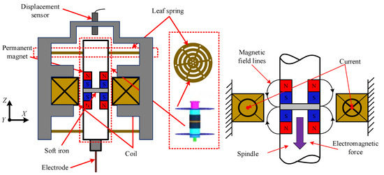
Figure 1.
Structure of single-degree-of-freedom controllable magnetic actuator.
In the process of micro-hole EDM, when the inter-electrode voltage is in a broken circuit, the discharge channel between the tool electrode and the workpiece cannot be formed at this time, and EDM cannot be performed. Therefore, the magnetic actuator is required to quickly drive the electrode to move downward slightly, maintain an effective inter-electrode machining voltage, and promote the normal machining of EDM. When the inter-electrode voltage is in a short circuit, the electric erosion products between the tool electrode and the workpiece cannot be discharged in time and the EDM process cannot be carried out normally. Therefore, it is necessary to quickly drive the electrode to move upward slightly by the magnetic actuator to promote the discharge of the electric erosion products and the normal operation of the EDM.
2.2. Dynamic Model of the Magnetic Actuator
Figure 2 shows the dynamics model of the magnetic actuator mover, in which the moving direction of the mover is the state of downward movement.
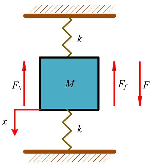
Figure 2.
Stress analysis of magnetic actuator mover.
Assume that the downward displacement of the mover of this magnetic actuator in the axial Z direction is x. When ignoring the external disturbance, according to Newton’s second law, the axial motion equation of the magnetic actuator mover can be expressed as:
The relationship between the output electromagnetic force of the magnetic actuator and the input current can be expressed as:
where F is the combined force, F1 is the electromagnetic force, Ff is the frictional resistance, F0 is the discharge force, M is the mass of the mover, a is an acceleration of the motion of the mover, k is the spring constant of the elastic sheet positioning, x is the axial displacement of the mover, c is the friction coefficient, v is the movement speed of the mover, Ki is the stiffness coefficient of the current, and i is the input current of the coil.
Substituting Formula (3) into Formula (1), a mathematical model of the magnetic actuator mover can be obtained:
The Laplace transform of Formula (4) can be obtained:
where s is the complex variable.
Then, the transfer function of the mathematical model of the magnetic actuator mover can be obtained as:
Table 1 shows the experimental parameters of the dynamic model of the magnetic actuator mover. Substituting the model parameters into Formula (6), the transfer function between the output displacement X(s) and the input coil current I(s) is:

Table 1.
Dynamic model parameters.
3. Magnetic Actuator Inter-Electrode Voltage Control System
Figure 3 shows the block diagram of the inter-electrode voltage control system of the magnetic actuator for micro-EDM, which is a voltage closed-loop control. The inter-electrode voltage signal is detected by the average voltage detection device and used as the feedback signal of the control system. The feedback voltage between the inter-electrode and the given reference voltage is sent to the controller for processing. The output voltage signal of the controller obtains the control current on the coil of the magnetic actuator through the power amplifier and completes the movement of the electrodes of the magnetic actuator. Through the closed-loop control system, the inter-electrode voltage can be controlled near the ideal machining voltage, which increases the probability of normal discharge, thereby effectively improving the efficiency of micro-EDM.
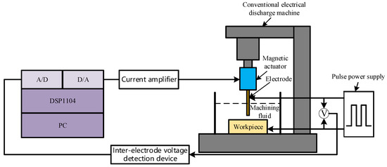
Figure 3.
Block diagram of the inter-electrode voltage control system of the magnetic actuator for micro-EDM.
3.1. Conventional PID Controller
Figure 4 shows the structure diagram of the conventional PID controller. In Figure 4, Vr(t) is the target value, which is the desired value of the inter-electrode voltage of the micro-EDM. Vs(t) is the feedback value, which is the current value of the inter-electrode voltage of the micro-EDM. e(t) is the input signal of the PID controller, which is the difference between the feedback value of the inter-electrode voltage of the EDM and the desired value of the inter-electrode voltage. Kp is the proportional adjustment coefficient. Ki is the integral adjustment coefficient. Kd is the differential adjustment coefficient. u(t) is the output signal of the PID controller. I(t) is the value of the coil control current of the magnetic actuator.
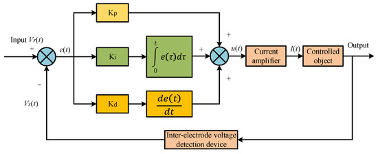
Figure 4.
Structure diagram of the conventional PID controller.
The proportional adjustment coefficient Kp can improve the system’s control accuracy and response speed. The integration adjustment coefficient Ki can eliminate the steady-state error of the system and improve the control accuracy. The differential adjustment coefficient Kd effectively eliminates oscillations in the regulation process, which affect the steady-state performance and response speed of the control system, and predicts the dynamics of the variation of the input deviation value of the controller. The mathematical model can be described as follows:
The control variables Kp, Ki, and Kd were debugged based on engineering experience. Based on this, the controller of this micro-EDM control system was further designed.
3.2. Fuzzy PID Controller
In the control process, the parameters of conventional PID control cannot be modified once they are set. The performance of the controller depends on the three parameters of PID. Generally speaking, the effect of conventional PID control depends on an accurate mathematical model of the controlled object, while the magnetic actuator is a nonlinear system, so an accurate mathematical model of this EDM system is difficult to establish. Fuzzy control does not depend on the precise mathematical model of the controlled object, and its corresponding control rules are established based on the characteristics of the controlled system, expert knowledge, and engineering experience, which can realize the online adjustment of control parameters within a certain range and have better applicability. Therefore, we combine fuzzy control and PID control to design a fuzzy PID controller to realize their complementary advantages.
The fuzzy controller consists of four main modules: the fuzzification module, fuzzy reasoning module, knowledge base module and the defuzzification module [26,27]. Figure 5 shows the schematic diagram of the inter-electrode voltage control system of the fuzzy PID control magnetic actuator for micro-EDM.
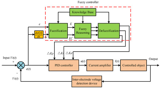
Figure 5.
Schematic diagram of the inter-electrode voltage control system of the fuzzy PID control magnetic actuator for micro-EDM.
First, the conventional PID control parameters are adjusted based on engineering experience. Then, based on this, the fuzzy controller corrects the control parameters of the conventional PID online in real-time based on the error value and the rate of change of the error value during the regulation process. Finally, the fuzzy PID controller determines the proportional adjustment coefficient Kp, the integral adjustment coefficient Ki, and the differential adjustment coefficient Kd. The calculation formulas are as follows:
where Kp0 is the initial proportional coefficient, Ki0 is the initial integral coefficient, Kd0 is the initial differential coefficient, ΔKp is the proportional coefficient correction amount, ΔKi is the integral coefficient correction amount, ΔKd is the differential coefficient correction amount.
Selection of the fuzzy domain needs to be combined with the actual control situation, and the key point is the fuzzy partitioning of the input variables and control variables. Since the variables have different ranges of values, the basic domains of each variable are first mapped to a standardized domain with different correspondences, respectively. Usually, the correspondence is taken as a quantization factor. Then, the domain is fuzzily divided and fuzzy subsets are defined. Fuzzy control rules are formulated based on expert knowledge and engineering experience. In this paper, the two input variables of the fuzzy control system are the inter-electrode voltage error e and its rate of change ec, and the fuzzy domain E and EC of the input variables are both set to [−6, 6]. The three output variables of the fuzzy control system are ΔKp, ΔKi, and ΔKd, and the fuzzy domain of the output variables are set to (−3, 3). The corresponding fuzzy language subsets of the input and output variables of the fuzzy control system are all (negative large (NB), negative medium (NM), negative small (NS), zero (ZO), positive small (PS), positive medium (PM), positive large (PB)). The quantization factors of the input variables of the fuzzy control system are Ke0 = 6, Kec0 = 0.3. The scaling factors of the output variables of the fuzzy control system are Ep0 = 0.002, Ei0 = 0.35, Ed0 = 0.0002. The affiliation function is trigonometric, the fuzzy reasoning is the Mamdani method, and the defuzzification is the centroid method. The fuzzy rule table of the fuzzy PID control system is shown in Table 2.
Table 2.
Fuzzy control rules table of ΔKp, ΔKi, ΔKd.
Fuzzy PID control also has limitations. Due to the structure of the fuzzy controller itself, the determination of the domain of fuzzy control in the control process is limited by expert experience and cannot be changed once it is set, so the adaptive ability of the fuzzy controller is limited. If the working conditions of the control system are changed, the control system will not be effectively controlled according to the original parameter settings.
4. Design of the Domain Adjustment Mechanism
The idea of a variable domain overcomes the above limitations. Based on fuzzy PID control, a domain adjustment mechanism is introduced, which expands the fuzzy domain as the error increases and contracts the fuzzy domain as the error decreases while keeping the number of fuzzy subsets and fuzzy rules unchanged. When the error is small, adding appropriate number of fuzzy rules indirectly makes the fuzzy control rules more suitable for the control system and more effective in the whole control process. This solves the problem of low control accuracy in fuzzy control due to fewer control rules near the zero point.
4.1. Design of Variable Domain Contraction-Expansion Factor
The adjustment rule of the variable domain relates to the increase and decrease of the quantization factor being equivalent to the expansion and contraction of the input variable domain, and the increase and decrease of the scaling factor being equivalent to the expansion and contraction of the output variable domain. The domain contraction-expansion factor is the key to the variable domain fuzzy controller design, and plays a crucial role in the control performance. In this paper, the contraction-expansion factor is selected based on fuzzy control. In the domain adjustment mechanism, we use two fuzzy controllers for fuzzy reasoning and obtains the contraction-expansion factor of the adjustment quantization factor and the scale factor, respectively. In this way, the expansion and contraction of the fuzzy domain of input and output of the control system can be realized.
Let the input variables in the fuzzy PID controller be the error e, its rate of change ec, and the output variables are ΔKp, ΔKi, and ΔKd. Then, the domain adjustment mechanism can be divided into the input domain adjustment mechanism and the output domain adjustment mechanism, where the contraction-expansion factors of the input variable fuzzy domain are αe and αec, and the contraction-expansion factors of the output variable fuzzy domain are βp, βi, and βd, respectively.
After the contraction-expansion factor adjusts the initial fuzzy domain, the formulas for the two quantization factors after control system regulation are as follows:
where Ke0 and Kec0 are the initial quantization factors, and Ke and Kec are the adjusted quantization factors.
The formulas for the three scaling factors after control system regulation are as follows:
where Ep0, Ei0, and Ed0 are the initial scaling factors, and Ep, Ei, Ed are the adjusted scaling factors.
The final correction values for the three parameters of the variable domain fuzzy PID control are as follows:
where Kp0, Ki0, and Kd0 are the initial values of proportional, integral, and differential coefficients of conventional PID control, respectively, and Kp, Ki, and Kd are the final corrected values of proportional, integral, and differential coefficients of fuzzy PID control, respectively.
4.2. Rule Design of Variable Domain Regulator
In the domain adjustment mechanism, the two input variables of the fuzzy control system are the inter-electrode voltage error e and its rate of change ec, and the fuzzy domains E and EC of the input variables are both set to (−6, 6), and the fuzzy subset linguistic values of the fuzzy control system input variables are expressed as (negative large (NB), negative medium (NM), negative small (NS), zero (ZO), positive small (PS), positive medium (PM), and positive large (PB)). The contraction-expansion factors to adjust the contraction-expansion change of the input domain are αe and αec, respectively. Then, the fuzzy domains αE and αEC are both (0, 1.5), and their fuzzy subset linguistic values are all expressed as (medium compression (M), light compression (S), keep constant (Z), light expansion (B)). The contraction-expansion factors that adjust the output domain contraction-expansion change are βp, βi, and βd, respectively, then the fuzzy domains βP, βI, and βD are all (0, 2), and their fuzzy subset linguistic values are all expressed as (large compression (CB), medium compression (CM), small compression (CS), keep constant (Z), small expansion (AS), medium expansion (AM), large expansion (AB)). The variable domain fuzzy PID controller is established using MATLAB/Simulink, and the membership function can be selected in the fuzzy control module. Since the triangular membership function has higher sensitivity, it is chosen to use the triangular membership function, as shown in Figure 6 and Figure 7, for the membership functions of the input domain contraction-expansion factors and the output domain contraction-expansion factors, respectively.
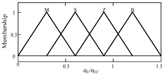
Figure 6.
Membership functions of αE and αEC.
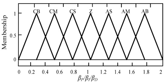
Figure 7.
Membership functions of βP, βI, and βD.
Like the fuzzy control in fuzzy PID control, the membership function is a triangular membership function, the fuzzy reasoning is the Mandani method, and the defuzzification is the centroid method. The fuzzy relationship between input and output variables can be determined based on expert knowledge, engineering experience, and the variation relationship between input and output variables. As shown in Table 3 and Table 4, the fuzzy rule table of the contraction-expansion factor regulates the contraction-expansion change of the input domain, and the fuzzy rule table of the contraction-expansion factor regulates the contraction-expansion change of the output domain are shown respectively.
Table 3.
Fuzzy control rules table of αe, αec.
Table 4.
Fuzzy control rules table of βp, βi, and βd.
5. Simulation Analysis of Magnetic Actuator Control System for Micro-EDM
5.1. Variable Domain Fuzzy PID Control System
Figure 8 shows the inter-electrode voltage control system of the variable domain fuzzy PID control magnetic actuator. With the variable domain fuzzy PID controller as the core, the simulation model of the inter-electrode voltage control system of the magnetic actuator for micro-EDM was established in the MATLAB/Simulink module, and the performance and effect of the variable domain fuzzy PID controller were tested.
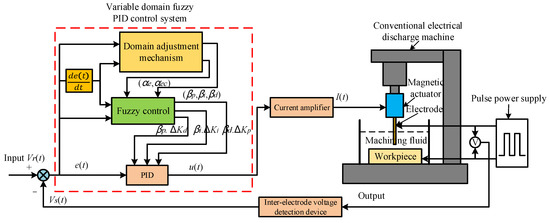
Figure 8.
Magnetic actuator inter-electrode voltage control system with variable domain fuzzy PID.
Figure 9 shows the simulation model of the domain regulation mechanism for the variable domain fuzzy PID control, which mainly consists of the input domain contraction-expansion factor (a) and the output domain contraction-expansion factor (b).
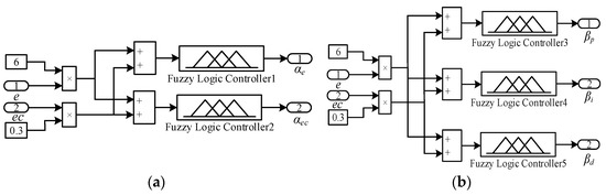
Figure 9.
Domain adjustment mechanism. (a) Input domain contraction-expansion factor; (b) output domain contraction-expansion factor.
5.2. Simulation Results and Analysis
The control system was simulated and analyzed in MATLAB/Simulink module with the following conditions: inter-electrode reference voltage value Vr(t) = 1.50 V, the actual inter-electrode voltage = 46.5 V, the current amplifier scale factor Kw = 0.77, the average inter-electrode voltage detection factor Ku = 20000/31, and the PID parameters adjusted to Kp0 = 0.15, Ki0 = 0.0002, Kd0 = 0.002. Figure 10 shows the simulation curve of inter-electrode voltage control of the magnetic actuator for the micro-EDM.
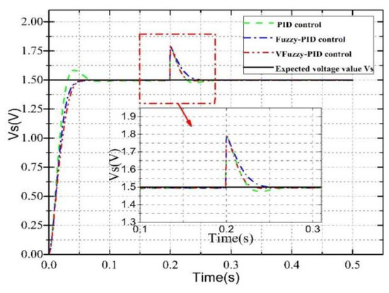
Figure 10.
Simulation curve of inter-electrode voltage control of the magnetic actuator for micro-EDM.
Table 5 shows the comparison of various control performance indexes of conventional PID control, fuzzy PID control, and variable domain fuzzy PID control.
Table 5.
Comparison of simulation parameters.
The simulation comparison analysis showed that increasing the inter-electrode voltage value by 0.3 V at 0.2 s for this control system was equivalent to increasing the inter-electrode voltage value by 9 V in the actual EDM process, which was used to simulate the inter-electrode voltage variation in the non-normal EDM process. Conventional PID control has overshoot, whereas fuzzy PID, and variable domain fuzzy PID control has a strong anti-interference ability and steady-state performance. During abnormal processing, the variable domain fuzzy PID control regulation speed is faster.
6. Experimental Research
To test the actual processing effect of the magnetic actuator control system for micro-EDM, machining experiments were conducted on the micro-EDM machine tool. The experimental study was conducted for four cases: traditional micro-EDM, conventional PID control magnetic actuator and traditional micro-EDM cooperative control, fuzzy PID control magnetic actuator and traditional micro-EDM cooperative control, and variable domain fuzzy PID control magnetic actuator and traditional micro-EDM cooperative control.
6.1. Build an Experimental Platform
Figure 11 shows the micro EDM experimental system, which is mainly composed of a micro EDM machine, magnetic actuator, dSPACE1104, computer, current power amplifier, switching DC power supply, and an inter-electrode voltage detection circuit. This low-pass filter with a cut-off frequency of 300 Hz is added after the inter-electrode voltage detection circuit to filter out the high frequency signal, and the high frequency, high voltage signal is filtered by the detection circuit to obtain a safe voltage signal after bucking, which is input to the controller. The basis for using copper as the electrode material for EDM is that copper has good electrical conductivity, thermal conductivity and high melting point, and copper electrodes are more suitable for micro-EDM.
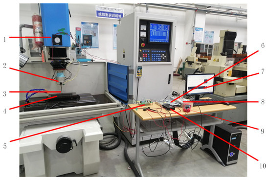
Figure 11.
Experimental system of micro-EDM. 1: Micro electrical discharge machining. 2: Magnetic actuator. 3: Tool electrode. 4: Machining workpiece. 5: Discharge gap voltage detection circuit. 6: Switching DC power supply. 7: Computer. 8: dSPACE1104. 9: Multimeter. 10: Current power amplifier.
Table 6 shows the parameter settings of the micro-EDM machine tool.
Table 6.
Parameters of micro-EDM machine tool.
6.2. Experimental Process
In micro-EDM, the gap voltage signal is detected and processed by the average voltage detection circuit. The detected inter-electrode voltage signal is the feedback signal Vs(t). The reference voltage Vr(t) is set to 1.5 V, which corresponds to the gap voltage between the electrode and the workpiece of 46.5 V in the actual machining. The inter-electrode voltage signal detected by the average voltage detection circuit is used as the feedback signal for the controller. The feedback signal is A/D converted by the dSPACE1104 input port, and the feedback voltage Vs(t) is compared with the reference voltage Vr(t), and the inter-electrode voltage error e and its rate of change ec are used as the input signal for the controller. The voltage signal ur(t) output from the controller is D/A converted by the dSPACE1104 output port, and the voltage signal ur(t) is converted by the power amplifier into a current signal Ir(t) that is fed into the coil of the magnetic actuator, which drives the electrode in the axial direction for fast micro-positioning so that the micro-EDM is always kept within the effective discharge range.
To verify that compared with the traditional micro-EDM, conventional PID control magnetic actuator and traditional micro-EDM cooperative control and fuzzy PID control magnetic actuator and traditional micro-EDM cooperative control, the variable domain fuzzy PID control magnetic actuator and traditional micro-EDM cooperative control has the advantages of good robustness, high adaptive ability, and anti-interference ability, which can significantly improve the dynamic and static performance of the control system.
6.3. Experimental Results and Analysis
6.3.1. Comparison of Discharge Status
To monitor the discharge status in real-time during EDM of micro small holes, the inter-electrode voltage detection circuit detects the feedback voltage Vs(t), which is then used for data acquisition by a digital signal processor (dSPACE1104). The feedback voltage is 0 V when the short-circuit is discharged. When the discharge state is a broken- circuit, the feedback voltage is 3 V, and the actual inter-electrode voltage is 90 V. And the effective discharge range is within the range of 20% (0.6 V) to 80% (2.4 V) of the broken-circuit inter-electrode voltage. Figure 12 shows the inter-electrode feedback voltage diagram for the four machining cases. Comparing the above four machining cases, it can be seen that the variable domain fuzzy PID controlled magnetic actuator can better reduce the number of short-circuit and broken-circuit of the gap voltage and be more sensitive to the short-circuit and broken-circuit, thus effectively improving the EDM efficiency.
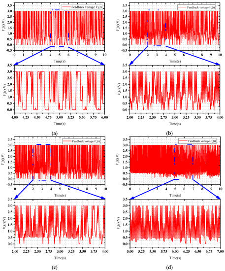
Figure 12.
Inter-electrode feedback voltage. (a) Traditional micro-EDM. (b) Conventional PID control magnetic actuator and traditional micro-EDM cooperative control. (c) Fuzzy PID control magnetic actuator and traditional micro-EDM cooperative control. (d) Variable domain fuzzy PID control magnetic actuator and traditional micro-EDM cooperative control.
6.3.2. Comparison of Processing Efficiency
To better observe the effect of the magnetic actuator control system on the machining efficiency of micro EDM, four sets of machining experiments were conducted for the above four machining cases. For each group of EDM experiments, under the same processing conditions, the small hole processing experiments were conducted with a small hole depth range of 0~1.5 mm, and the processing time of small holes was recorded every 0.05 mm. To exclude the small holes affected by larger abnormal discharge, a number of processing experiments were conducted, and then the average value of their respective times was taken as the sample data.
Figure 13 shows the relationship between the micro EDM depth and machining time for the above four machining cases. Analysis of the curve in the figure shows that the machining speed slows down with the increase of machining depth. The reason is that when the machining depth is less than 1mm, the machined small hole is very shallow, the machining electric erosion products are easily discharged, and the electric erosion products removal effect has little impact on the machining efficiency. However, when the EDM depth of micro-hole is greater than 1mm, the electric erosion products removal becomes more and more difficult, and the machining electric erosion products cannot be discharged in time, resulting in low EDM machining efficiency. The magnetic actuator can drive the electrodes in the axial direction (Z direction) for rapid micro-positioning, which can effectively change the state of inter-electrode discharge and promote the removal of inter-electrode electric erosion products. In conclusion, the variable domain fuzzy PID control is more effective for this control system, the control system is more stable, and the machining efficiency is higher.
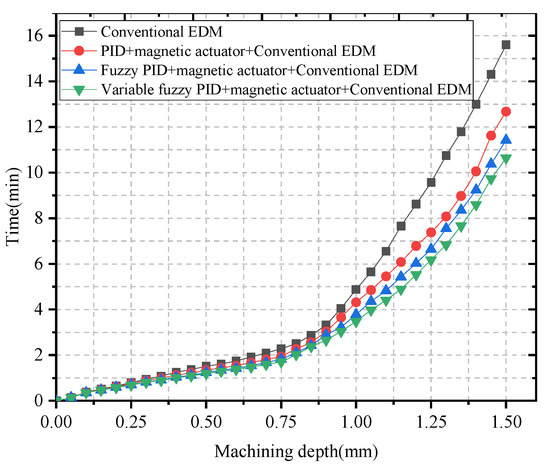
Figure 13.
Relationship between micro EDM depth and machining time.
To further observe the effect of the inter-electrode voltage control system of the magnetic actuator for micro-EDM on the machining efficiency, four groups of small holes with a depth of 1 mm were machined in the above four machining cases. The machining speed of eight small holes was selected as sample data for each group of experiments. Figure 14 shows the comparison of machining efficiency.
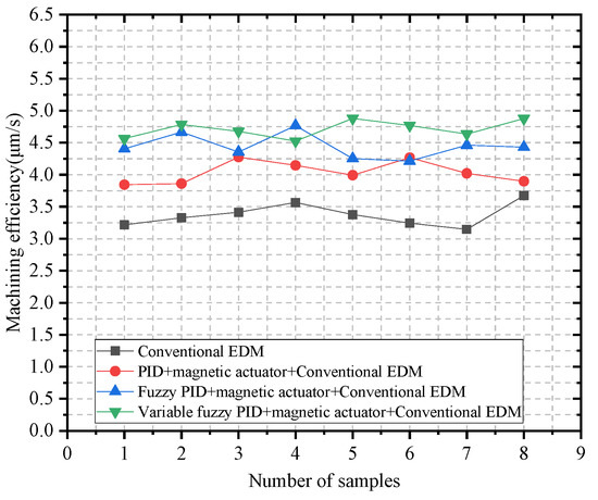
Figure 14.
Comparison of micro-EDM efficiency.
Table 7 shows an analysis of experimental results. The experimental results show that, compared with the traditional micro-EDM, the processing efficiency of the conventional PID control magnetic actuator and traditional micro-EDM cooperative control was increased by 20%. The processing efficiency of the fuzzy PID control magnetic actuator and traditional micro-EDM cooperative control was increased by 31.8%. The processing efficiency of the Variable domain fuzzy PID control magnetic actuator and traditional micro-EDM cooperative control was increased by 40%.
Table 7.
Experimental result analysis table.
6.3.3. Comparison of Machining Surface Quality
Figure 15 shows a physical image of the machined workpiece with a machining depth of 1 mm. From left to right are traditional micro-EDM, conventional PID control magnetic actuator and the traditional micro-EDM cooperative control, Fuzzy PID control magnetic actuator and the traditional micro-EDM cooperative control, variable domain fuzzy PID control magnetic actuator and the traditional micro-EDM cooperative control. By comparing the surface quality of the machined workpiece, it can be seen that the variable domain fuzzy PID control magnetic actuator and the traditional micro-EDM cooperative control had better machining results. The surface carbon accumulation of the machined workpiece was significantly reduced, and the surface quality of the machined workpiece was improved.
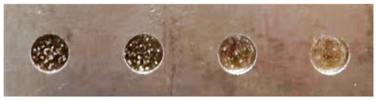
Figure 15.
Image of machined workpiece.
7. Conclusions and Future Work
In this paper, a magnetic local actuator with a controllable single degree of freedom, high precision, and fast response for micro EDM is introduced. The magnetic actuator can be directly connected to the spindle of a traditional micro-EDM machine tool. Aiming at the problem of narrow discharge gap servo control, variable domain fuzzy control and PID control were combined, and a variable domain fuzzy PID controller was designed, which brought about intelligence of the control process and improved the performance of the control system. Under the conditions of electrical discharge machining, the system was used to control the magnetic actuator drive electrode to quickly and accurately position in the axial direction, improve the effective discharge probability of micro-EDM, and attain high-speed and high-precision micro-EDM. Simulation and experimental results showed that compared with traditional micro-EDM machine, the processing efficiency of the conventional PID control magnetic actuator and the traditional micro-EDM cooperative control was increased by 20%. The processing efficiency of the fuzzy PID control magnetic actuator and the traditional micro-EDM cooperative control was increased by 31.8%. The processing efficiency of the variable domain fuzzy PID control magnetic actuator and the traditional micro-EDM cooperative control was increased by 40%.
Based on this, in future research, we will consider the use of new type-2 and type-3 fuzzy logic systems to improve this control system, and we will study a multi-degree-of-freedom magnetic actuator and its control method, as well as verifying the control performance of the multi-degree-of-freedom magnetic actuator through EDM experiments.
Author Contributions
C.X.: software, drawing, experiments, data collection and processing, reading and summarization of all literature, writing-original draft, writing-review & editing; F.X.: writing-review & editing; F.S.: supervision, writing-review & editing; X.Z.: supervision, writing-review & editing; J.J.: writing-review & editing; B.L.: writing-review & editing; K.O.: writing-review & editing. All authors have read and agreed to the published version of the manuscript.
Funding
This research is supported by National Natural Science Fund of China (No. 52005345, No. 52005344), National Key Research and Development Project (No. 2020YFC2006701), China Scholarship Council (No. 202208210071), Scientific Research Fund Project of Liaoning Provincial Department of Education (No. LFGD2020002), Major Project of the Ministry of Science and Technology of Liaoning Province (No. 2022JH1/10400027).
Institutional Review Board Statement
Not applicable.
Informed Consent Statement
Not applicable.
Data Availability Statement
Not applicable.
Acknowledgments
We thank Zhou R., Zhao C., Pei W.Z., and Wang D. for their suggestions and recommendations.
Conflicts of Interest
The authors declare no conflict of interest.
References
- Prakash, V.; Kumar, P.; Singh, P.; Hussain, M. Micro-electrical discharge machining of difficult-to-machine materials: A review. Proc. Inst. Mech. Eng. Part B J. Eng. Manuf. 2019, 233, 339–370. [Google Scholar] [CrossRef]
- Kumar, D.; Singh, N.K.; Bajpai, V. Recent trends, opportunities and other aspects of micro-EDM for advanced manufacturing: A comprehensive review. J. Braz. Soc. Mech. Sci. Eng. 2020, 42, 2172–2191. [Google Scholar] [CrossRef]
- Gostimirovic, M.; Pucovsky, V.; Sekulic, M.; Rodovanovic, M.; Madic, M. Evolutionary multi-objective optimization of energy efficiency in electrical discharge machining. J. Mech. Sci. Technol. 2018, 32, 4775–4785. [Google Scholar] [CrossRef]
- Shabgard, M.R.; Gholipoor, A.; Baseri, H. A review on recent developments in machining methods based on electrical discharge phenomena. Int. J. Adv. Manuf. Technol. 2016, 87, 2081–2097. [Google Scholar] [CrossRef]
- Gohil, V.; Puri, Y.M. Turning by electrical discharge machining: A review. Proc. Inst. Mech. Eng. Part B J. Eng. Manuf. 2017, 231, 195–208. [Google Scholar] [CrossRef]
- Rafaqat, M.; Mufti, N.A.; Ahmed, N.; Rehman, A.U.; AlFaify, A.Y.; Farooq, M.U.; Saleh, M. Hole-Making in D2-Grade Steel Tool by Electric-Discharge Machining through Non-Conventional Electrodes. Processes 2022, 10, 1553. [Google Scholar] [CrossRef]
- Gero, E.; Yan, J.W. Direct Observation of Discharge Phenomena in Vibration-Assisted Micro EDM of Array Structures. Micromachines 2022, 13, 1286. [Google Scholar] [CrossRef]
- Huang, Y.H.; Zhang, Q.H.; Xing, Q.X.; Yao, Z.Y.; Li, J.C. Effects of electrode rotational speed on processing performances of AISI 304 in micro-electrical discharge machining. Int. J. Adv. Manuf. Technol. 2019, 105, 1665–1674. [Google Scholar] [CrossRef]
- Tsai, M.Y.; Fang, C.S.; Yen, M.H. Vibration-assisted electrical discharge machining of grooves in a titanium alloy (Ti-6A-4V). Int. J. Adv. Manuf. Technol. 2018, 97, 297–304. [Google Scholar] [CrossRef]
- Jadam, T.; Sahu, S.K.; Datta, S.; Masanta, M. EDM performance of Inconel 718 superalloy: Application of multi-walled carbon nanotube (MWCNT) added dielectric media. J. Braz. Soc. Mech. Sci. Eng. 2019, 41, 1–20. [Google Scholar] [CrossRef]
- Jiang, Y.; Ping, X.L.; Zhang, Y.; Zhao, W.S. Effects of gas medium on submersed gas-flushing electrical discharge machining of different metal materials. Int. J. Adv. Manuf. Technol. 2021, 115, 3679–3687. [Google Scholar] [CrossRef]
- Wang, J.; Jia, Z.X. Efficiency improvement in electrical discharge machining (EDM) of constant section cavity based on experimental study and numerical calculations. Prod. Eng. 2018, 12, 567–578. [Google Scholar] [CrossRef]
- Guo, Y.F.; Ling, Z.B.; Zhang, X.Y.; Feng, Y.R. A magnetic suspension spindle system for small and micro holes EDM. Int. J. Adv. Manuf. Technol. 2018, 94, 1911–1923. [Google Scholar] [CrossRef]
- Zhang, X.Y.; Shinshi, T.; Shimokohbe, A.; SATO, T.; Miyake, H.; Nakagawa, T. High-speed electrical discharge machining by using a 5-DOF controlled maglev local actuator. J. Adv. Mech. Des. Syst. Manuf. 2008, 2, 493–503. [Google Scholar] [CrossRef][Green Version]
- Hiroyuki, N.; Toshiro, H. A Novel Electromagnetic Actuator Based on Displacement Amplification Mechanism. IEEE/ASME Trans. Mechatron. 2015, 20, 1607–1615. [Google Scholar] [CrossRef]
- Feng, Y.R.; Guo, Y.F.; Ling, Z.B.; Zhang, X.Y. Investigation on machining performance of micro-holes EDM in ZrB2 -SiC ceramics using a magnetic suspension spindle system. Int. J. Adv. Manuf. Technol. 2019, 101, 2083–2095. [Google Scholar] [CrossRef]
- Feng, Y.R.; Guo, Y.F.; Ling, Z.B.; Zhang, X.Y. Micro-holes EDM of superalloy Inconel 718 based on a magnetic suspension spindle system. Int. J. Adv. Manuf. Technol. 2019, 101, 2015–2026. [Google Scholar] [CrossRef]
- Yang, F.; Yang, J.; Yao, K.; Hua, H. Adaptive Voltage Position Control for Pulse Power Supply in Electrical Discharge Machining. IEEE Trans. Ind. Electron. 2019, 66, 5895–5906. [Google Scholar] [CrossRef]
- Chen, X.L.; Tong, W.; Mao, Y.; Zhao, T. Interval Type-2 Fuzzy Dynamic High Type Control of Permanent Magnet Synchronous Motor with Vector Decoupling Method. Actuators 2021, 10, 293. [Google Scholar] [CrossRef]
- Zheng, T.; Xu, X.Z.; Lu, X.; Xu, F. Learning adaptive sliding mode control for repetitive motion tasks in maglev rotary table. IEEE Trans. Ind. Electron. 2021, 69, 1836–1846. [Google Scholar] [CrossRef]
- Lu, Y.T.; Tan, C.; Ge, W.Q.; Li, B.; Lu, J.Y. Improved Sliding Mode-Active Disturbance Rejection Control of Electromagnetic Linear Actuator for Direct-Drive System. Actuators 2021, 10, 138. [Google Scholar] [CrossRef]
- Chen, D.F.; Chiu, S.P.C.; Cheng, A.B.; Ting, J.C. Electromagnetic Actuator System Using Witty Control System. Actuators 2021, 10, 65. [Google Scholar] [CrossRef]
- Zhu, H.Q.; Gu, Z.W. Active disturbance rejection control of 5-degree-of-freedom bearingless permanent magnet synchronous motor based on fuzzy neural network inverse system. ISA Trans. 2020, 101, 295–308. [Google Scholar] [CrossRef] [PubMed]
- Repinaldo, J.P.; Koroishi, E.H.; Lara-molina, F.A. Neuro-fuzzy control applied on a 2DOF structure using electromagnetic actuators. IEEE Lat. Am. Trans. 2021, 19, 75–82. [Google Scholar] [CrossRef]
- Chen, J.W. Modeling and Decoupling Control of a Linear Permanent Magnet Actuator Considering Fringing Effect for Precision Engineering. IEEE Trans. Magn. 2021, 57, 1–15. [Google Scholar] [CrossRef]
- Wang, N.; Li, Z.; Liang, X.L.; Zhang, J.Q. Design of UAV yaw Angle controller based on variable domain fuzzy PID. J. Phys. Conf. Ser. 2021, 1754, 012112. [Google Scholar] [CrossRef]
- Lin, C.L.; Liu, H.F.; Sun, H.J.; Zheng, Z.Y.; Chen, Z. Implementation of Fuzzy Self-tuning Proportional Integral Derivative Controller on Sample-tube Spin Control System in Nuclear Magnetic Resonance Spectrometer. Chin. J. Anal. Chem. 2011, 39, 506–510. [Google Scholar] [CrossRef]
Publisher’s Note: MDPI stays neutral with regard to jurisdictional claims in published maps and institutional affiliations. |
© 2022 by the authors. Licensee MDPI, Basel, Switzerland. This article is an open access article distributed under the terms and conditions of the Creative Commons Attribution (CC BY) license (https://creativecommons.org/licenses/by/4.0/).