
High Precision Magnetic Levitation Actuator for Micro-EDM

 ,
, 
Abstract
1. Introduction
2. 5-DOF Controlled Magnetic Levitation Actuator
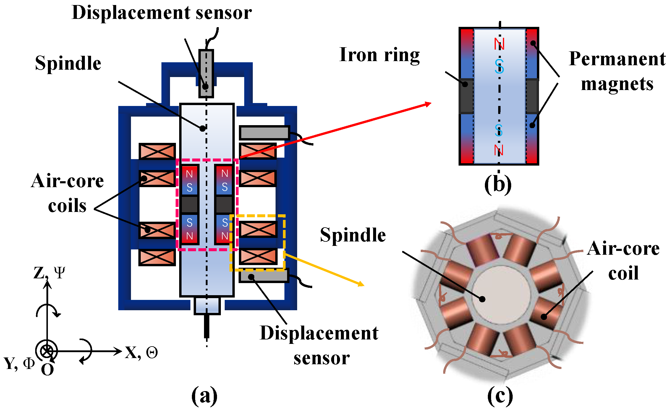
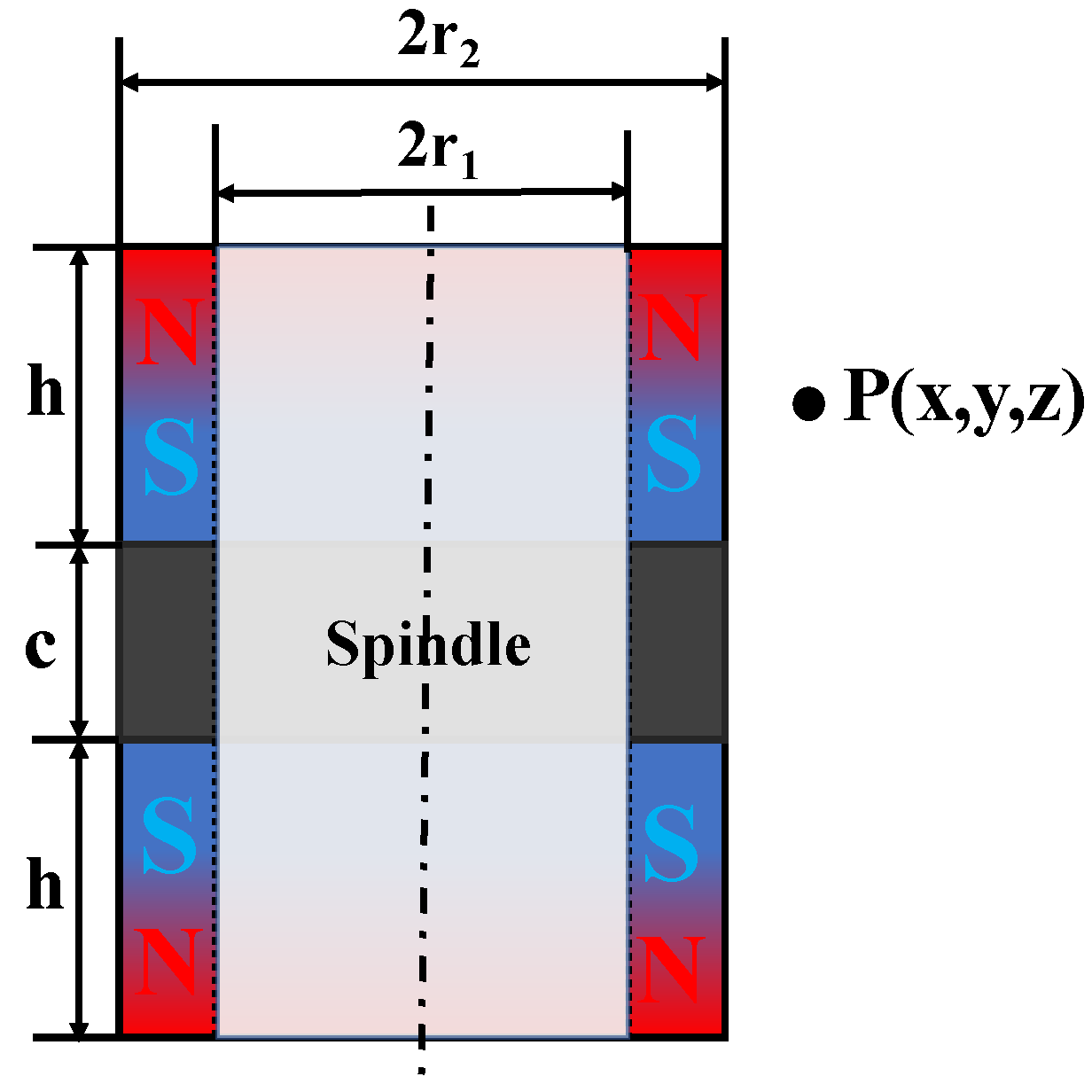
2.1. The Structure of Magnetic Levitation Actuator
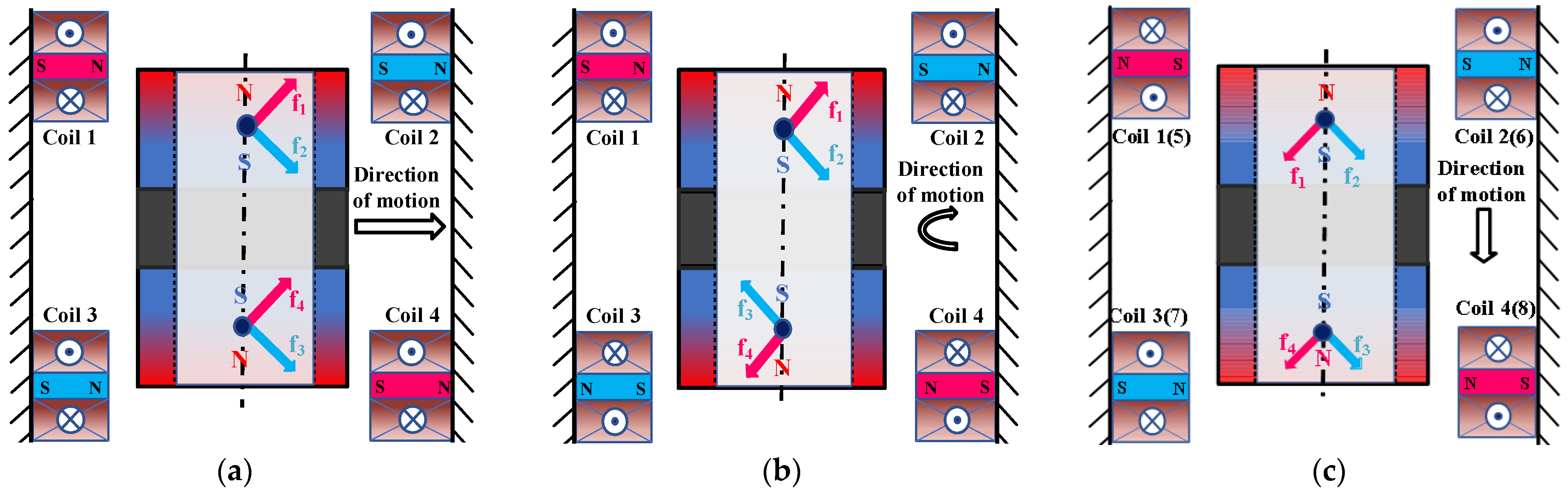
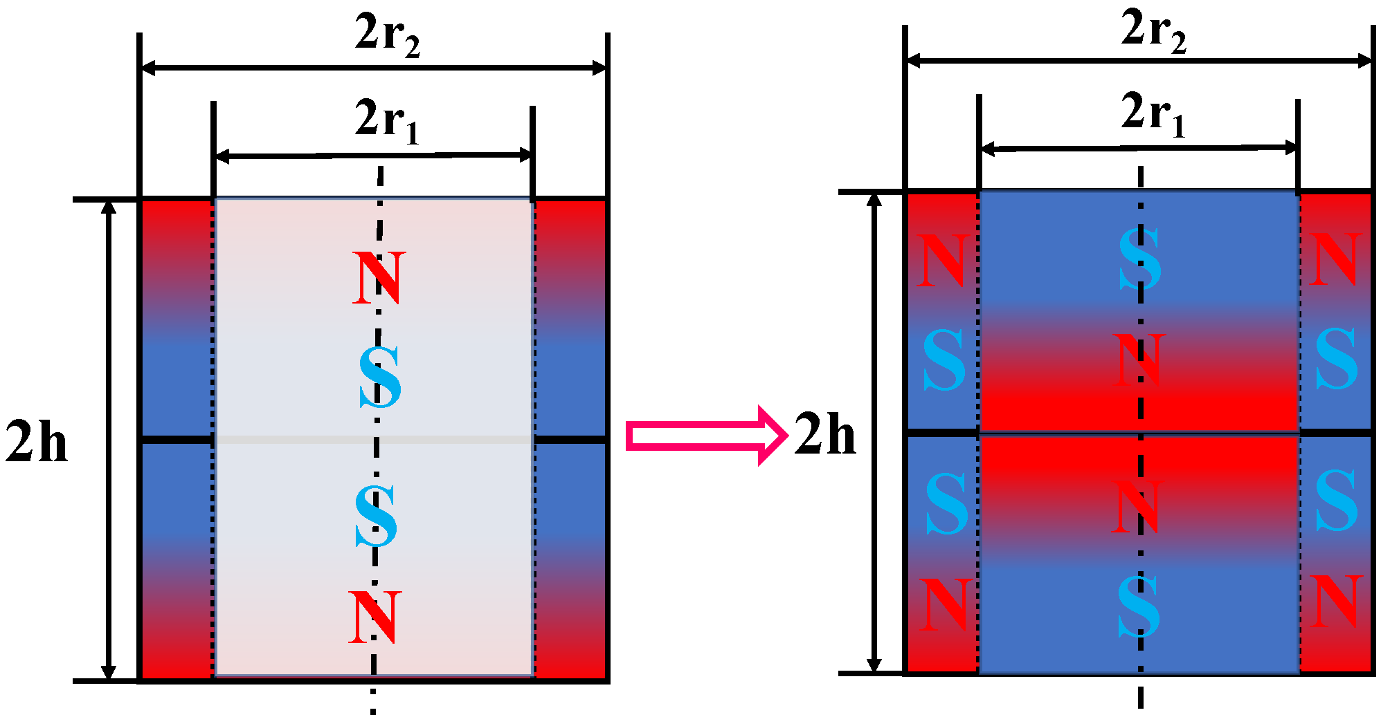
2.2. The Principle of Magnetic Levitation Actuator
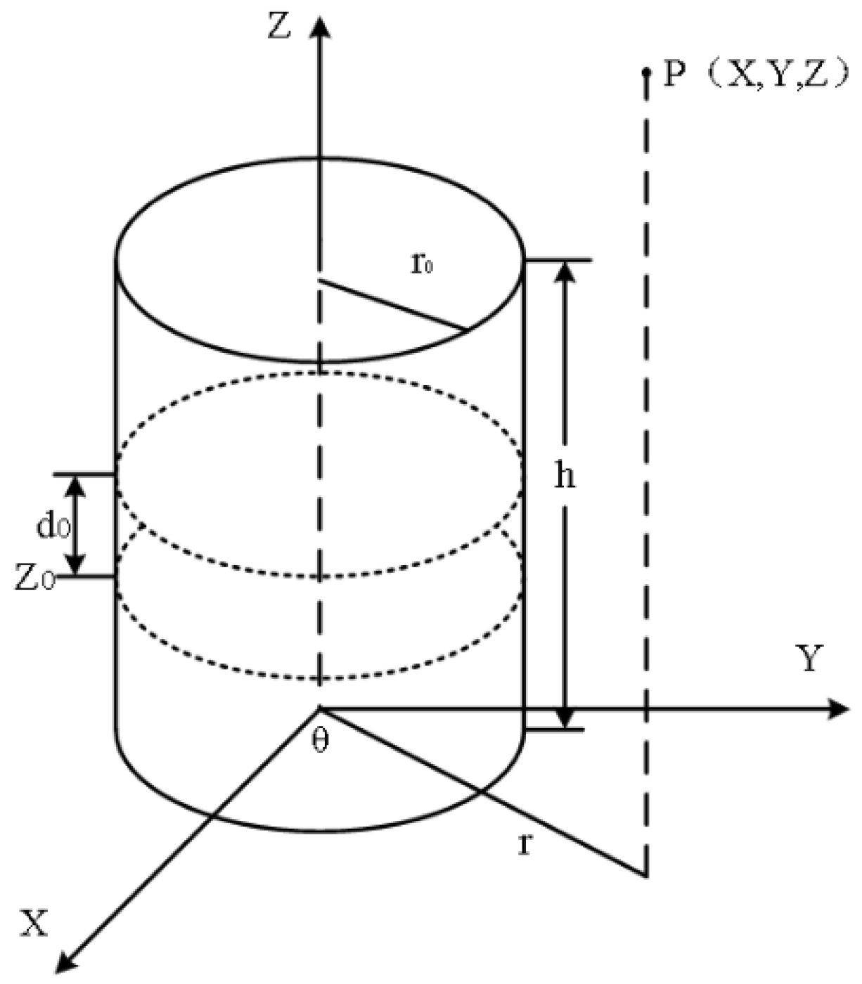
2.3. Mathematical Model of 5-DOF Magnetic Levitation Actuator
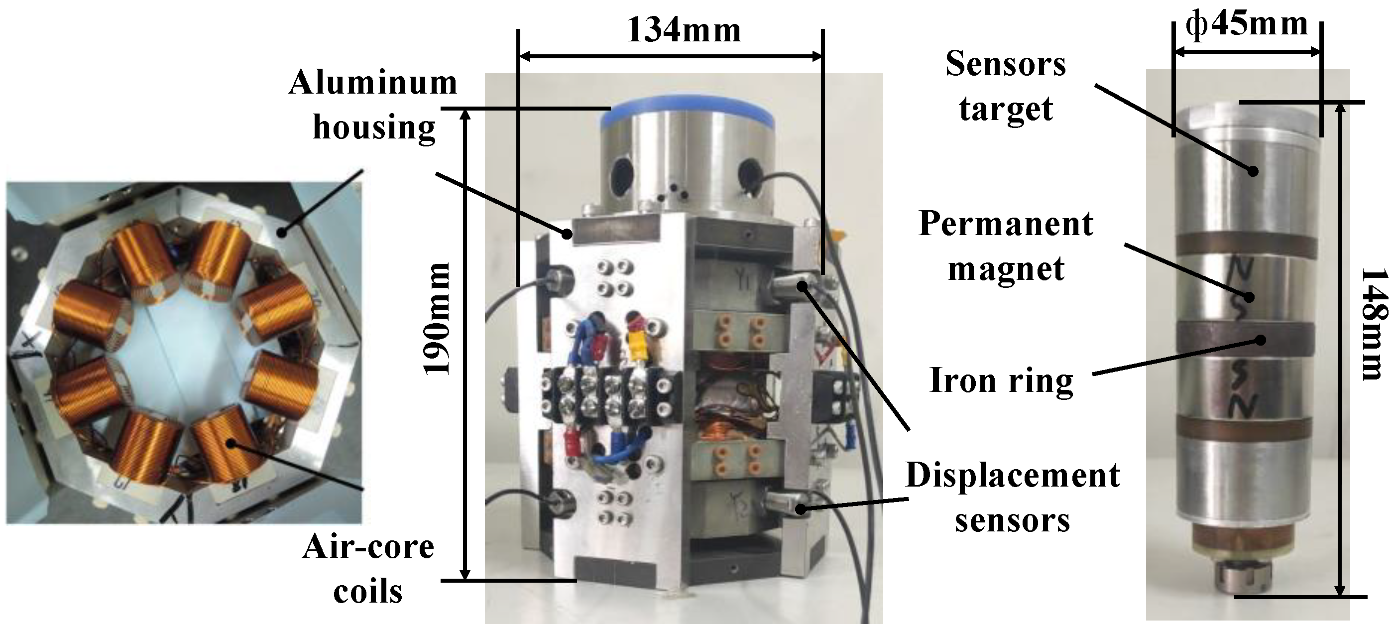
2.4. Experimental Magnetic Levitation Actuator
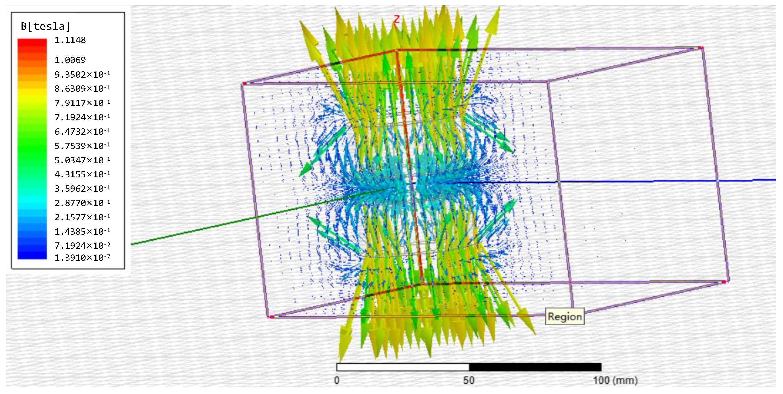
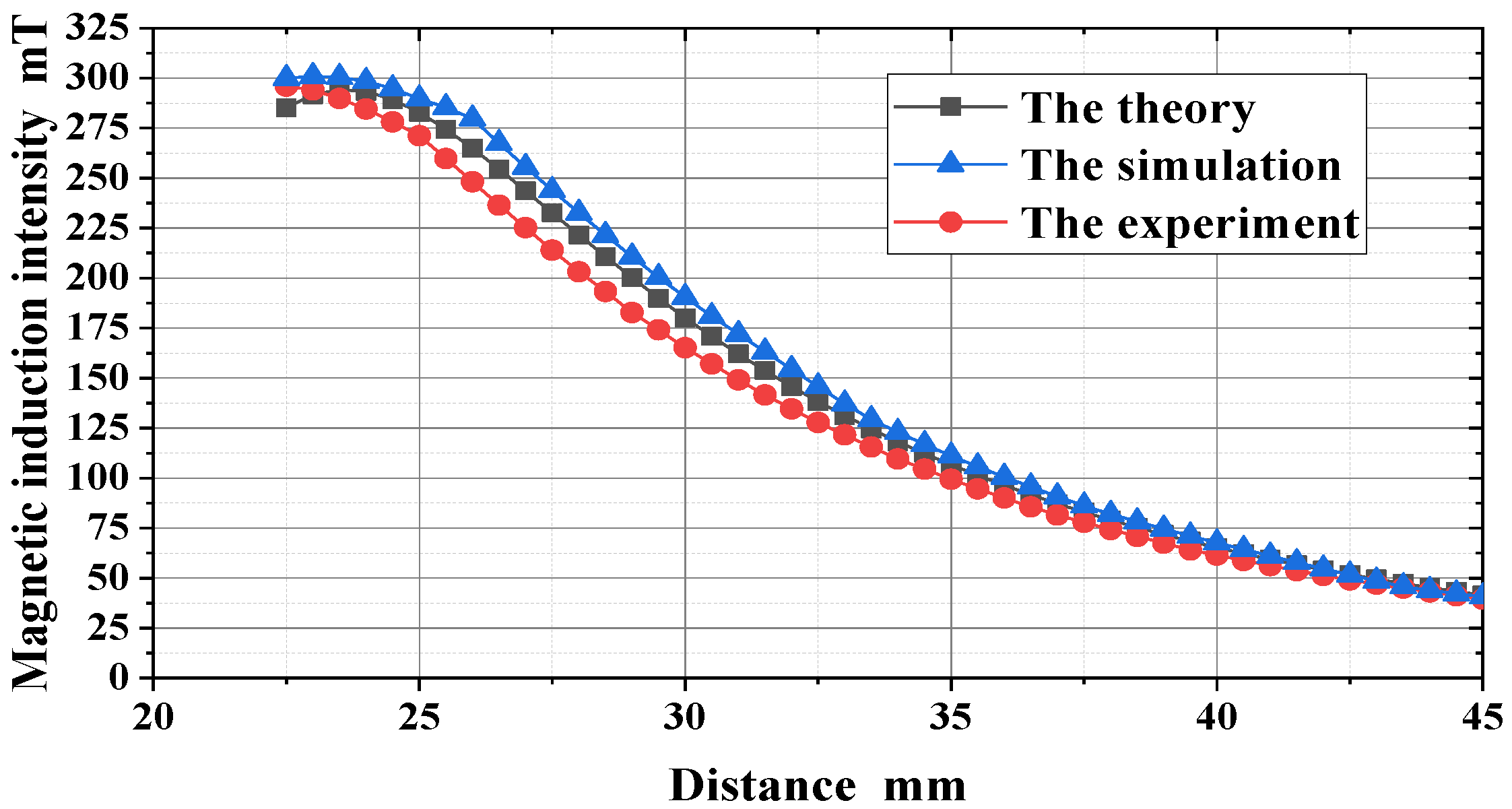
3. Magnetic Field Characteristic Analysis
4. 5-DOF Magnetic Levitation Actuator Controller Design and Positioning Performance
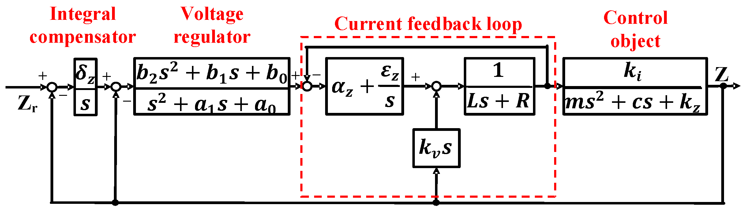
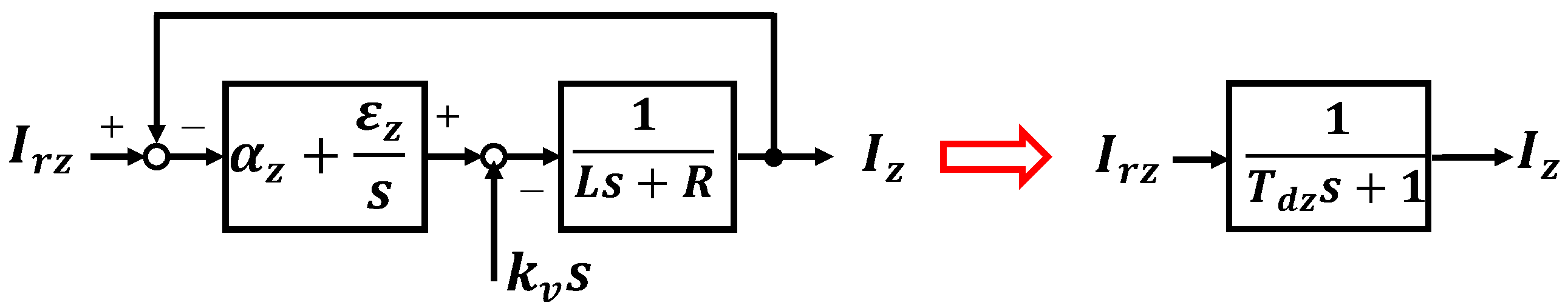
4.1. Actuator Motion Control System
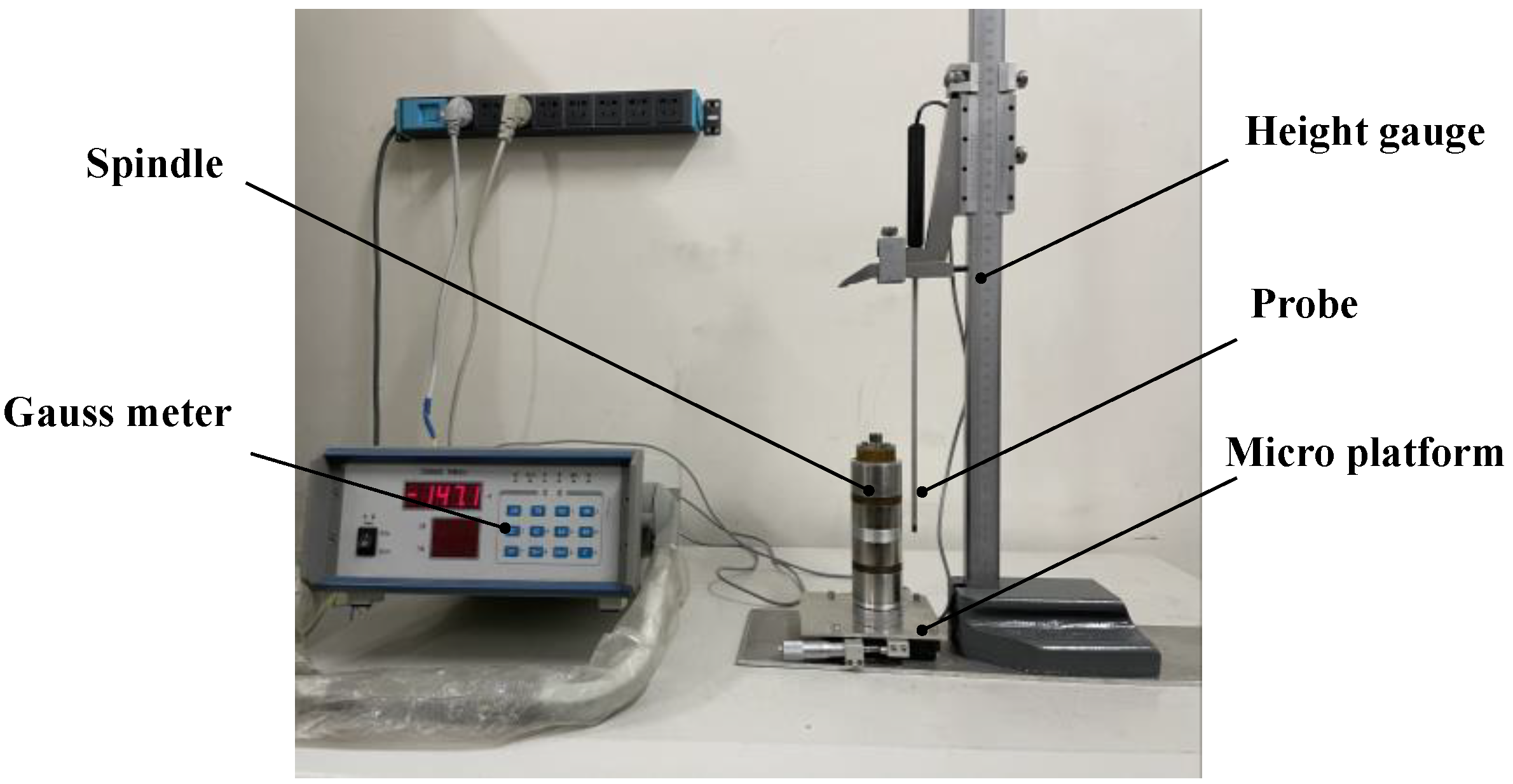
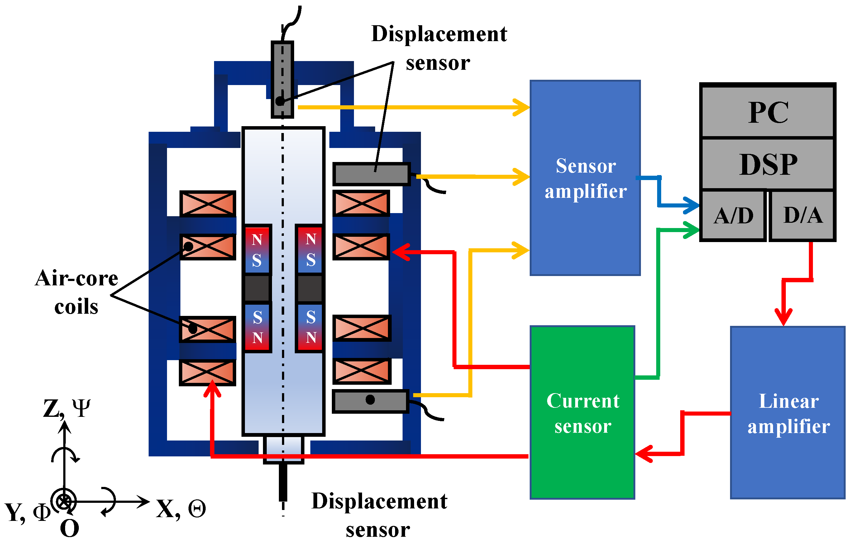
4.2. Composition of the Experimental System
4.3. Performance Test
5. Conclusions
Author Contributions
Funding
Institutional Review Board Statement
Informed Consent Statement
Data Availability Statement
Acknowledgments
Conflicts of Interest
References
- Prakash, V.; Kumare, P.; Singh, P.K.; Hussain, M.; Das, A.K.; Chattopadhyaya, S. Micro-electrical discharge machining of difficult-to-machine materials: A review. Proc. Inst. Mech. Eng. Part B J. Eng. Manuf. 2019, 233, 339–370. Available online: https://journals.sagepub.com/doi/10.1177/0954405417718591 (accessed on 5 June 2022). [CrossRef]
- Urso, D.G.; Giardini, C.; Ravasio, C. Effects of Electrode and Workpiece Materials on the Sustainability of Micro-EDM Drilling Process. Int. J. Precis. Eng. Manuf. 2018, 19, 1727–1734. Available online: https://link.springer.com/article/10.1007/s12541-018-0200-2 (accessed on 5 June 2022).
- Suganthi, X.H.; Natarajan, U.; Sathiyamurthy, S.; Chidambaram, K. Prediction of quality responses in micro-EDM process using an adaptive neuro-fuzzy inference system (ANFIS) model. Int. J. Adv. Manuf. Technol. 2013, 68, 339–347. Available online: https://link.springer.com/article/10.1007/s00170-013-4731-5 (accessed on 5 June 2022). [CrossRef]
- Yang, F.; Yang, J.; Yao, K.; Hua, H. Adaptive Voltage Position Control for Pulse Power Supply in Electrical Discharge Machining. IEEE Trans. Ind. Electron. 2019, 66, 5895–5906. Available online: https://ieeexplore.ieee.org/document/8480869 (accessed on 5 June 2022). [CrossRef]
- Kumar, D.; Singh, N.K.; Bajpai, V. Recent trends, opportunities and other aspects of micro-EDM for advanced manufacturing: A comprehensive review. J. Braz. Soc. Mech. Sci. Eng. 2020, 42, 2172–2191. Available online: https://link.springer.com/article/10.1007/s40430-020-02296-4 (accessed on 10 July 2022). [CrossRef]
- Shabgard, M.R.; Gholipoor, A.; Baseri, H. A review on recent developments in machining methods based on electrical discharge phenomena. Int. J. Adv. Manuf. Technol. 2016, 87, 2081–2097. Available online: https://link.springer.com/article/10.1007/s00170-016-8554-z (accessed on 10 July 2022). [CrossRef]
- Gostimirovic, M.; Pucovsky, V.; Sekulic, M.; Radovanovic, M.; Madic, M. Evolutionary multi-objective optimization of energy efficiency in electrical discharge machining. J. Mech. Sci. Technol. 2018, 32, 4775–4785. Available online: https://link.springer.com/article/10.1007/s12206-018-0925-y (accessed on 10 July 2022). [CrossRef]
- Macedo, F.T.B.; Wiessner, M.; Hollenstein, C.; Kustera, F.; Wegenera, K. Dependence of Crater Formation in Dry EDM on Electrical Breakdown Mechanism. Procedia CIRP 2016, 42, 161–166. Available online: https://linkinghub.elsevier.com/retrieve/pii/S2212827116004960 (accessed on 12 June 2022). [CrossRef]
- Nahak, B.; Gupta, A. A review on optimization of machining performances and recent developments in electro discharge machining. Manuf. Rev. 2019, 6, 2. Available online: https://mfr.edp-open.org/articles/mfreview/full_html/2019/01/mfreview180009/mfreview180009.html (accessed on 12 June 2022). [CrossRef]
- Gohil, V.; Puri, Y.M. Turning by electrical discharge machining: A review. Proc. Inst. Mech. Eng. Part B J. Eng. Manuf. 2017, 231, 195–208. Available online: https://journals.sagepub.com/doi/10.1177/0954405415590560 (accessed on 12 June 2022). [CrossRef]
- Lee, C.H.; Lai, T.S. An Intelligent System for Improving Electric Discharge Machining Efficiency Using Artificial Neural Network and Adaptive Control of Debris Removal Operations. IEEE Access 2021, 9, 75302–75312. Available online: https://ieeexplore.ieee.org/document/9431212 (accessed on 25 June 2022). [CrossRef]
- Zhang, Z.; Zhang, Y.; Ming, W.Y.; Zhang, Y.M.; Cao, C.; Zhang, G.J. A review on magnetic field assisted electrical discharge machining. J. Manuf. Process. 2021, 64, 694–722. Available online: https://www.sciencedirect.com/science/article/abs/pii/S1526612521000955?via%3Dihub (accessed on 18 June 2022). [CrossRef]
- Guo, Y.F.; Ling, Z.B.; Zhang, X.Y.; Feng, Y.R. A magnetic suspension spindle system for small and micro holes EDM. Int. J. Adv. Manuf. Technol. 2018, 94, 1911–1923. Available online: https://link.springer.com/article/10.1007/s00170-017-0990-x (accessed on 18 June 2022). [CrossRef]
- Chen, C.H.; Hu, Y.F.; Wu, H.C.; Song, C.S. Parametric design and experiment of maglev actuators for microgravity vibration isolation system. Int. J. Appl. Electromagn. Mech. 2018, 58, 319–335. Available online: https://content.iospress.com/articles/international-journal-of-applied-electromagnetics-and-mechanics/jae180037 (accessed on 12 July 2022). [CrossRef]
- Zhang, T.; Le, Q.Y.; Zhu, W.G. Structure and Suspension Force Analysis of Six-Pole Five Degrees of Freedom AC Hybrid Magnetic Bearing. IEEE Trans. Magn. 2021, 57, 6. Available online: https://ieeexplore.ieee.org/document/9386118 (accessed on 12 July 2022). [CrossRef]
- Lee, H.R.; Kim, K.C.; Lee, J. Review of Maglev Train Technologies. IEEE Trans. Magn. 2006, 42, 1917–1925. Available online: https://ieeexplore.ieee.org/document/1644911 (accessed on 12 July 2022).
- Maximov, S.; Montañez, F.G.; Perez, R.E.; Galvan, J.C.O.; Mestiza, H.A. Analytical Analysis of Magnetic Levitation Systems with Harmonic Voltage Input. Actuators 2020, 9, 82. [Google Scholar] [CrossRef]
- Yaseen, M.H.A. Investigation on planar electromagnetic levitation system using lead compensation and LQR controllers. Electr. Eng. 2020, 102, 725–736. Available online: https://link.springer.com/article/10.1007/s00202-019-00905-7 (accessed on 12 July 2022). [CrossRef]
- Zhao, C.; Sun, F.; Jin, J.J.; Tang, J.H.; Xu, F.C.; Li, Q. Analysis of Quasi-Zero Power Characteristic for a Permanent Magnetic Levitation System with a Variable Flux Path Control Mechanism. IEEE/ASME Trans. Mechatron. 2021, 26, 437–447. Available online: https://ieeexplore.ieee.org/document/9204846 (accessed on 14 July 2022). [CrossRef]
- Poletkin, K. On the Static Pull-In of Tilting Actuation in Electromagnetically Levitating Hybrid Micro-Actuator: Theory and Experiment. Actuators 2021, 10, 256. [Google Scholar] [CrossRef]
- He, D.J.; Shinshi, T.; Nakai, T. Development of a Lens Driving Maglev Actuator for ep Piercing. Key Eng. Mater. 2012, 523–524, 774–779. Available online: https://www.scientific.net/KEM.523-524.774 (accessed on 14 July 2022).
- Zheng, T.; Lu, X.; Xu, F.Q.; Xu, X.Z. Optimisation method of magnetic levitation actuator for rotary table. IET Electr. Power Appl. 2020, 14, 893–900. Available online: https://ietresearch.onlinelibrary.wiley.com/doi/10.1049/iet-epa.2019.0788 (accessed on 14 July 2022). [CrossRef]
- Kato, H.; Komori, M.; Asami, K.; Sakai, N. Development of one-axis controlled bearingless motor and its application to a centrifugal pump for extremely low temperature. Int. J. Appl. Electromagn. Mech. 2020, 64, 1287–1294. Available online: https://content.iospress.com/articles/international-journal-of-applied-electromagnetics-and-mechanics/jae209447 (accessed on 18 July 2022). [CrossRef]
- Murakami, I.; Zhao, Y.M.; Tashiro, T. Stabilization of a Magnetic Repulsive Levitation Flywheel System Using a High-Efficiency Superconducting Magnetic Bearing. Actuators 2022, 11, 180. [Google Scholar] [CrossRef]
- Arsénio, A.J.; Silva, F.F.; Fernands, J.F.P.; Branco, P.J.C. Optimization of the Guiding Stability of a Horizontal Axis HTS ZFC Radial Levitation Bearing. Actuators 2021, 10, 311. [Google Scholar] [CrossRef]
- Hopf, T.; Richter, M.; Schüßler, B.; Rinderknecht, S. Control Strategies for Highly Gyroscopic Outer Rotors with Diametral Enlargement in Active Magnetic Bearings. Actuators 2022, 11, 91. [Google Scholar] [CrossRef]
- Zhu, H.Y.; Teo, T.J.; Pang, C.K. Magnetically Levitated Parallel Actuated Dual-Stage (Maglev-PAD) System for Six-Axis Precision Positioning. IEEE/ASME Trans. Mechatron. 2019, 24, 1829–1838. Available online: https://ieeexplore.ieee.org/document/8764447 (accessed on 14 July 2022). [CrossRef]
- Duan, J.A.; Zhou, H.B.; Guo, N.P. Electromagnetic Design of a Novel Linear Maglev Transportation Platform with Finite-Element Analysis. IEEE Trans. Magn. 2011, 47, 260–263. Available online: https://ieeexplore.ieee.org/document/5601781 (accessed on 14 July 2022). [CrossRef]
- Zhou, H.B.; Deng, H.; Duan, J. Hybrid Fuzzy Decoupling Control for a Precision Maglev Motion System. IEEE/ASME Trans. Mechatron. 2018, 23, 389–401. Available online: https://ieeexplore.ieee.org/document/8100985 (accessed on 20 July 2022). [CrossRef]
- Ahn, D.; Jin, J.W.; Yun, H.; Jeong, J. Development of a Novel Dual Servo Magnetic Levitation Stage. Actuators 2022, 11, 147. [Google Scholar] [CrossRef]
- Sun, F.; Pei, W.Z.; Zhao, C.; Jin, J.J.; Xu, F.C.; Zhang, X.Y. Permanent Maglev Platform Using a Variable Flux Path Mechanism: Stable Levitation and Motion Control. IEEE Trans. Magn. 2022, 58, 8300410. Available online: https://ieeexplore.ieee.org/document/9772652 (accessed on 20 July 2022). [CrossRef]
- Zhou, L.; Wu, J.J. Magnetic Levitation Technology for Precision Motion Systems: A Review and Future Perspectives. Int. J. Autom. Technol. 2022, 16, 386–402. Available online: https://www.fujipress.jp/ijat/au/ijate001600040386/ (accessed on 22 July 2022). [CrossRef]
- Poletkin, K.V.; Asadollahbaik, A.; Kampmann, R.; Korvink, J.G. Levitating Micro-Actuators: A Review. Actuators 2018, 7, 17. [Google Scholar] [CrossRef]


| Variable Name | X (Y) Z θ (Φ) Direction | Unit | |
|---|---|---|---|
| mass of the spindle | m | 0.80 | kg |
| coil inductance | L | 35.4 | mH |
| coil resistance | R | 2.6 | Ω |
| torque | l | 25 | mm |
| rotational inertia | Jθ | 2 | kg·m2 |
| first-order delay system time constants | Td | 3.9 × 10⁻³ | / |
| current stiffness | ki | 4.2 | N·A−1 |
| air gap stiffness in the X direction | kx | 367.57 | N·m−1 |
| air gap stiffness in the Z direction | kz | 170.7 | N·m−1 |
| air gap stiffness in the θ direction | kθ | 9.19 | N·rad−1 |
| damping coefficient | c | 1 | N·s·m−1 |
| X (Y) Z θ (Φ) Direction Controller | |
|---|---|
| δx | 256.45 |
| δz | 256.50 |
| δθ | 3.07 × 10⁴ |
| a0x | 3.07 × 10⁵ |
| a0z | 1.49 × 10⁵ |
| a0θ | 4.53 × 10⁵ |
| a1x | 873.31 |
| a1z | 1.93 × 10³ |
| a1θ | 819.73 |
| b0x | 1.30 × 10⁸ |
| b0z | 6.78 × 10⁹ |
| b0θ | 1.79 × 10⁶ |
| b1x | 3.52 × 10⁶ |
| b1z | 8.50 × 10⁷ |
| b1θ | 3.09 × 10⁴ |
| b2x | 4.01 × 10⁴ |
| b2z | 2.16 × 10⁵ |
| b2θ | 93.14 |
| αx | 35 |
| αz | 35 |
| αθ | 35 |
| εx | 2565 |
| εz | 2565 |
| εθ | 2565 |
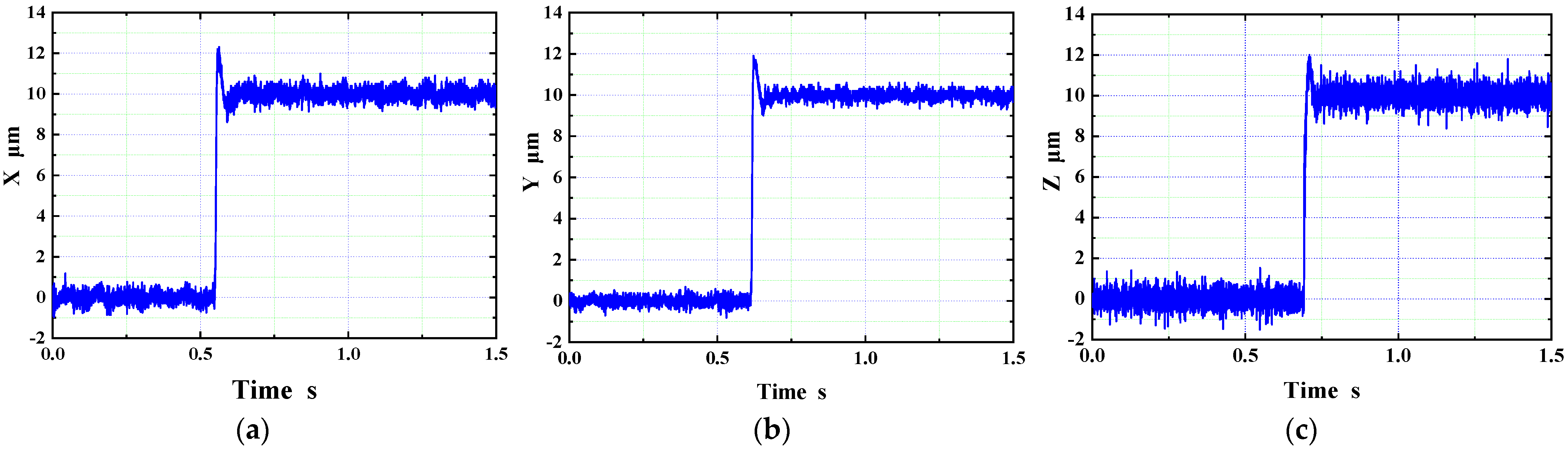
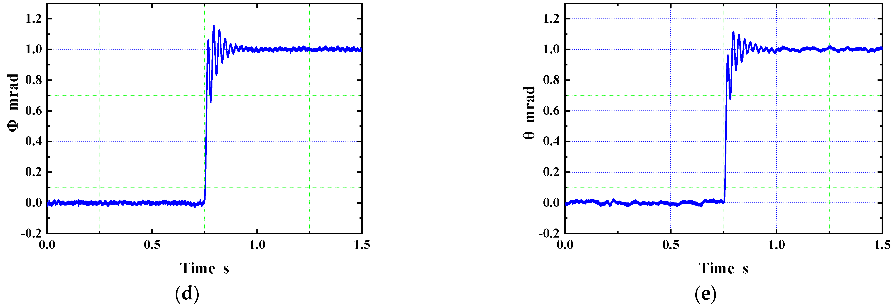
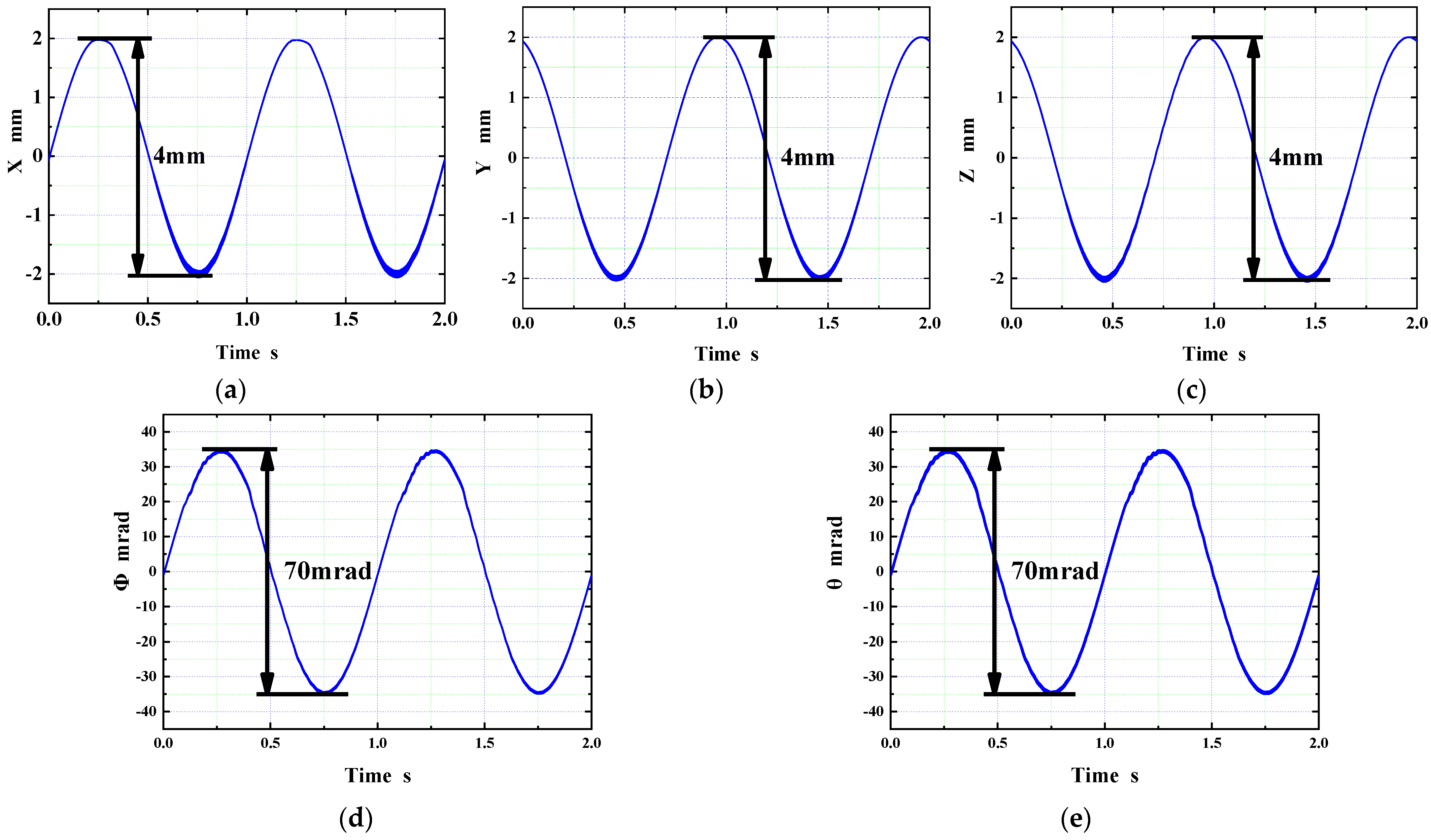
| Response Time | Stroke | Positioning Resolution | Bandwidth | |
|---|---|---|---|---|
| X direction | 6.7 ms | 4 mm | 1 μm | 101 Hz |
| Y direction | 6.8 ms | 4 mm | 1 μm | 101 Hz |
| Z direction | 26.3 ms | 4 mm | 1 μm | 51 Hz |
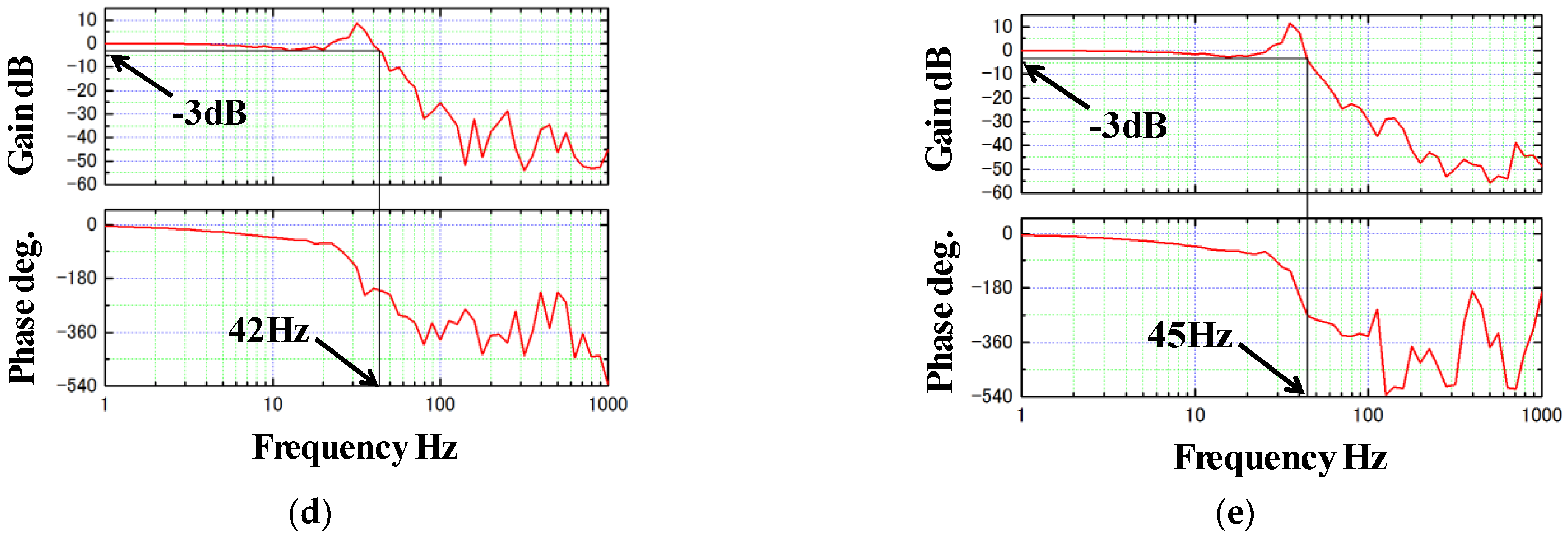
| Φ direction | 39.9 ms | 70 mrad | 25 μrad | 42 Hz |
| θ direction | 16.2 ms | 70 mrad | 20 μrad | 45 Hz |
Publisher’s Note: MDPI stays neutral with regard to jurisdictional claims in published maps and institutional affiliations. |
© 2022 by the authors. Licensee MDPI, Basel, Switzerland. This article is an open access article distributed under the terms and conditions of the Creative Commons Attribution (CC BY) license (https://creativecommons.org/licenses/by/4.0/).
Share and Cite
Luan, B.; Zhang, X.; Xu, F.; Yang, G.; Jin, J.; Xu, C.; Sun, F.; Oka, K. High Precision Magnetic Levitation Actuator for Micro-EDM. Actuators 2022, 11, 361. https://doi.org/10.3390/act11120361
Luan B, Zhang X, Xu F, Yang G, Jin J, Xu C, Sun F, Oka K. High Precision Magnetic Levitation Actuator for Micro-EDM. Actuators. 2022; 11(12):361. https://doi.org/10.3390/act11120361
Chicago/Turabian StyleLuan, Boran, Xiaoyou Zhang, Fangchao Xu, Guang Yang, Junjie Jin, Chengcheng Xu, Feng Sun, and Koichi Oka. 2022. "High Precision Magnetic Levitation Actuator for Micro-EDM" Actuators 11, no. 12: 361. https://doi.org/10.3390/act11120361
APA StyleLuan, B., Zhang, X., Xu, F., Yang, G., Jin, J., Xu, C., Sun, F., & Oka, K. (2022). High Precision Magnetic Levitation Actuator for Micro-EDM. Actuators, 11(12), 361. https://doi.org/10.3390/act11120361