Article

Development of Sliding Mode Controller Based on Internal Model Controller for Higher Precision Electro-Optical Tracking System

1
Key Laboratory of Optical Engineering, Chinese Academy of Sciences, Chengdu 610209, China
2
Institute of Optics and Electronics, Chinese Academy of Sciences, Chengdu 610209, China
3
University of Chinese Academy of Sciences, Beijing 100049, China
*
Author to whom correspondence should be addressed.
Actuators 2022, 11(1), 16; https://doi.org/10.3390/act11010016
Submission received: 1 December 2021 / Revised: 23 December 2021 / Accepted: 2 January 2022 / Published: 7 January 2022
(This article belongs to the Special Issue Design and Control of High-Precision Motion Systems)

Abstract

:
The electro-optical tracking system (ETS) on moving platforms is affected by the vibration of the moving carrier, the wind resistance torque in motion, the uncertainty of mechanisms and the nonlinear friction between frames and other disturbances, which may lead to the instability of the electro-optical tracking platform. Sliding mode control (SMC) has strong robustness to system disturbances and unknown dynamic external signals, which can enhance the disturbance suppression ability of ETSs. However, the strong robustness of SMC requires greater switching gain, which causes serious chattering. At the same time, the tracking accuracy of SMC has room for further improvement. Therefore, in order to solve the chattering problem of SMC and improve the tracking accuracy of SMC, an SMC controller based on internal model control (IMC) is proposed. Compared with traditional SMC, the proposed method can be used to suppress the strongest disturbance with the smallest switching gain, effectively solving the chattering problem of the SMC, while improving the tracking accuracy of the system. In addition, to reduce the adverse influence of sensor noise on the control effect, lifting wavelet threshold de-noising is introduced into the control structure to further improve the tracking accuracy of the system. The simulation and experimental results verify the superiority of the proposed control method.

1. Introduction

Electro-optical tracking system (ETS) is a complex high-precision directional servo tracking equipment which is integrated with optical, mechanical and electronic technology. ETS has the characteristics of fast response, small tracking error and strong disturbance rejection ability. This kind of equipment is widely applied to target tracking and pointing, naval ship tracking, UAV, satellite reconnaissance and observation systems [1,2,3]. Compared with the ETS with fixed base on the ground, the ETS installed on a moving platform is affected not only by the uncertainty of the tracking mechanism and the nonlinear friction between the frames, but also by factors such as the jitter of the satellite, the steering of the vehicle and the swing of the naval ship system due to wind and ocean current, so the disturbance is more complex in the form. These disturbance factors directly affect the stability and tracking accuracy of the ETS. Therefore, how to improve the tracking accuracy and the robust stability of the ETS on a moving platform is an important research project. Tian et al. [4] used the acceleration feedback control to enhance the stability of the closed-loop control system of fast steering mirrors (FSMs). Deng et al. [5] designed a disturbance observer (DOB) of the acceleration loop in the multi-loop feedback control to improve the disturbance rejection performance of the FSM system. Zhou and Li [6] proposed a fractional order control scheme to solve the contradiction between the error suppression ability and the stability margin in high-precision tracking control. Ren et al. [7] proposed a new nonlinear sliding mode DOB to compensate the high-frequency disturbance of electro-optical tracking. Zhou and Li [8] designed a trajectory-tracking control scheme for an ETS with nonlinear disturbance (such as friction) based on the super twisting extended state observer and the fractional order non-singular terminal sliding mode with the switching-type reaching law. These innovative control methods effectively improve the performance of the ETS control system in different ways.
Among various control schemes, sliding mode control (SMC) is a powerful nonlinear control technology, which has a simple control structure, easy to implement, with fast response, insensitivity and strong robustness to system external disturbance and model uncertainties [9,10,11,12]; therefore, it has attracted a lot of attention and has been applied in the ETS [7,8,13,14,15,16]. However, the traditional SMC suppresses external disturbance and model uncertainties mainly by adding a discontinuous switching term. Only when the gain of the switching term is required to be greater than the upper bound of disturbance can the sliding mode condition of the SMC be guaranteed and the disturbance be suppressed [17]; this means that the control action has high frequency oscillation and it might bring potential damage to the actuator [18]. The ETS, similar to the FSM, is a typical direct drive system, in which a steering mirror is directly driven by a linear drive motor and the high-frequency control action easily causes current harmonics and torque pulsation; thus, it directly brings about the unexpected vibration of the steering mirror. When the ETS works on a moving platform, the disturbance caused by the movement of the moving platform has the characteristics of large amplitude and a wide range of amplitude variation, so it is difficult to choose an appropriate switching gain to suppress these disturbances. When a large switching gain is selected, it is easy to cause the mismatch of the switching gain and disturbance amplitude, resulting in chattering, which directly causes the steering mirror to vibrate. However, the angle vibration of the fast mirror causes twice the vibration of the beam deflection angle, according to the working principle of the steering mirror. Therefore, it seriously affects the tracking accuracy and even cause the tracking target to exceed the field of the position-sensitive detector (PSD).
At present, several different methods have been developed to alleviate the chattering problem. Through the use of a nonlinear DOB, Yang et al. [19] devised an SMC technique for chattering reduction. Seungmin et al. [20] suggested a new adaptive law for the SMC method to accomplish efficient switching gain tuning at the sliding surface. Goel and Mobayen [21] created an adaptive control law that eliminates the necessity for a priori knowledge of the system uncertainties’ upper bounds. For nonlinear systems with external disturbances, Alattas et al. [22] suggested an adaptive non-singular fast terminal SMC with integral surface and a novel adaptive rate to relieve the chattering problem. Karami et al. [23] proposed an adaptive integral terminal SMC approach for uncertain nonlinear systems subject to input saturation and external disturbance by integrating adaptive integral SMC with nonlinear extended-state observer. This strategy substantially reduces the chattering effect while also eliminating uncertainties. Moreover, the chattering problem can be alleviated by introducing a thin boundary layer [24] around the sliding mode surface, using a smooth function instead of the sign function [25]; however, the main drawback of smoothing design is the need of the trade-off between control performance and chattering elimination. Second-order SMC [26] is also a method to reduce chattering. However, it is difficult to deduce the slip variables many times, which limits the superiority of second-order SMC [27]. Chattering can also be reduced by adaptively adjusting the switching gain using fuzzy rules [28], but the design of fuzzy rules is relatively complex and it mostly relies on the experience and knowledge of researchers to establish a fuzzy rule control table [29].
Among various methods for alleviating chattering, combining SMC with the DOB is an attractive method. Its idea consists in making the designed switching gain only larger than the range of disturbance estimation error and not larger than the disturbance range through disturbance estimation and compensation, so as to alleviate chattering. However, the disadvantage of this method based on disturbance compensation is that it only relieves chattering, but the tracking ability of SMC is not obviously improved. It is equally important to reduce sliding mode chattering and improve system tracking accuracy for the high-precision ETS on a moving platform.
In the internal model control (IMC) method [30], the inverse of the object model was used to design the controller and the error between the controlled object and the model output was taken as the feedback signal. The DOB and IMC are very similar in structure, but they also have very important differences. The DOB only has the ability of disturbance estimation, while IMC has the ability of disturbance estimation and tracking. When the disturbance is zero and the nominal model is accurate, theoretically, neither of the feedback loops can be activated. In this case, there is only a physical model in the system based on the DOB, while the system based on IMC has a physical model and an open-loop controller and the system operates in an open-loop fashion. Therefore, the control system based on IMC can provide a better tracking effect.
In addition to chattering, it is usually required to know the model uncertainties and the limit value of disturbance in the design process of the SMC [31]. However, in practice, the limit value is not always obtainable [32]. Even after disturbance compensation, the limit value of disturbance compensation error is not easy to obtain. Too large parameters still cause a certain degree of chattering. Meanwhile, in the actual control system, system output is measured and obtained by the sensor, so it is inevitable to introduce sensor noise. Although the SMC has a certain ability to suppress noise, the measurement noise may still destroy the operation of the system, thus losing system robustness [33]. The accuracy of the measurement results directly affects closed-loop accuracy. Hence, effective noise removal plays a significant role in the actual system to ensure a better tracking accuracy. Linear low-pass filters are commonly used to overcome the adverse influence of measurement noise. However, the linear low-pass filter inevitably causes large phase lag in the control system [34]. Therefore, some scholars have developed other de-noising methods, such as the Kalman filter [35] and the nonlinear filtering algorithm [36].
To solve the problems mentioned above and further improve the tracking accuracy of the ETS on a moving platform, in this paper, an SMC design method based on IMC is proposed. First, the IMC method was utilized to compensate for most of the disturbance of the system and the tracking characteristics of IMC were used to provide a certain tracking amount for the system. Second, the disturbance compensation error was suppressed by appropriate SMC design and the tracking error of IMC was compensated at the same time. The main contributions of this paper are summarized as follows:
  • An SMC method based on IMC is proposed in this paper. Compared with the SMC method, this method can decrease chattering and the tracking error and, compared with the SMC based on the DOB, this method can reduce the tracking error and improve the disturbance suppression ability of the system.
  • A continuous function with fractional power is proposed as a part of the sliding mode reaching law, which can further weaken the sliding mode chattering and solve the problem that the upper bound of disturbance compensation error is unknown.
  • A solution of two-controller fusion design is presented based on the principle of system state decomposition.
  • The lifting wavelet threshold de-noising method was applied to the closed-loop control system for online de-noising and the feasibility and effects were verified by experiments.
The other parts of this paper are organized as follows: The electro-optical tracking control system is modeled in Section 2. Section 3 introduces the traditional SMC design method. Section 4 gives the principle of IMC; then, the control method proposed in this paper is designed based on IMC. In Section 5, lifting wavelet de-noising is introduced and applied to the control loop. Section 6 presents the simulation and experiments on an electro-optical tracking platform. Section 7 summarizes the whole paper.

2. ETS Model Analysis

The ETS based on the FSM has the characteristics of high resonance frequency, fast response, small dynamic lag error, small volume, lightness and flexibility and can be used for precise electro-optical tracking control. The ETS based on the FSM is shown in Figure 1a, composed of a two-dimensional mirror, image detector, controller, digital signal processor, power drive amplifier, drive motor, etc. The deflection direction of the mirror is adjusted through four motors to control the beam deflection angle and then reflect the beacon light to the target detector. The control task is to stabilize the beacon light in the geometric center of the target detector. In Figure 1b, using the potential and torque balance equation, we can obtain [37]
U a = R a I a + L a I ˙ a + K b θ ˙ C m I a = J L θ ¨ + f m θ ˙ + K m θ
where U a , I a , R a , L a , K b , C m , f m and K m are voltage, current, resistance, inductance, back EMF coefficient, torque coefficient, viscous friction and spring stiffness of motor, respectively. Considering that the armature inductance of the motor is relatively small, the model is further simplified. Let L a 0 ; then, the following can be derived:
U a = R a I a + K b θ ˙ C m I a = J L θ ¨ + f m θ ˙ + K m θ
The corresponding transfer function can be given as follows:
G p ( s ) = k s 2 + a s + b
where a = R a f m + K b C m J L R a and b = K m J L , k = C m J L R a . The system states are assumed as follows: x 1 = θ and x 2 = θ ˙ ; further, both model uncertainties and external disturbances are considered at the same time, so the state space model of the system can be described as
x ˙ 1 = x 2 x ˙ 2 = a + δ a x 2 b + δ b x 1 + k + δ k ( u + d e x ) y = x 1
where δ a , δ b and δ c indicate the model uncertainty; d e x is external disturbance; u = U a is the control input; and y is the system output.
Remark 1.
The ETS based on the FSM is a third-order system. By neglecting the armature inductance, the model order is reduced to simplify the model. On one hand, the armature inductance has little influence on the low-frequency characteristics of the system because of its small numerical value. On the other hand, for the SMC design, a higher order of the system means that a higher-order derivative of the input signal and a higher-order derivative of the error are needed. Generally, a higher-order derivative is not easy to obtain and a higher-order derivative of the error by difference calculation at the same time amplifies the measurement noise, which is not adverse to the practical control. Therefore, in this study, appropriate order reduction and simplification were made.

3. Traditional SMC

According to the equivalent disturbance theory [38], the system in (4) can be described as an equivalent system as follows:
x ˙ 1 = x 2 x ˙ 2 = a x 2 b x 1 + k ( u + d e q ) y = x 1
where d e q = d e x + k 1 ( δ k d e x + δ k u δ a x 2 δ b x 1 ) is called system lumped disturbance.
Assumption 1.
Let us suppose that the lumped disturbance of system (5) is bounded and d e q * = sup t > 0 d e q is defined.
The tracking error is defined as e = r y . Because the integral sliding mode surface can eliminate the smoothness of the arrival phase and the control law and enhance the adaptive ability of the system, in this paper, the integral-type sliding mode surface was selected as follows:
σ = e ˙ + α e + β 0 t e d t
where α and β are the parameters of the sliding mode surface. The design method of sliding mode controller based on the reaching law was adopted and the exponent reaching law given as follows:
σ ˙ = k c σ η s g n σ
where k c is the exponential convergence rate ( k c > 0 ) and η is the switching gain of the sliding mode surface ( η > 0 ). The traditional sliding mode control law can be designed as follows by combining them:
u c = k 1 ( r ¨ + a x 2 + b x 1 + α e ˙ + β e + k c σ + η sgn ( σ ) )
where r is the reference input.
If a positive definite Lyapunov function V = σ 2 / 2 is taken into account, from Equations (5), (6) and (8), the following can be derived:
V ˙ = σ σ ˙ = k c σ 2 η σ sgn ( σ ) k d e q σ = k c σ 2 η | σ | k d e q σ k c σ 2 η | σ | + | k d e q | | σ | | σ | ( η | k d e q | )
Remark 2.
On the basis of Assumption 1, it is learned that, as long as the switching gain in the control law is designed as η > k d e q * and V ˙ 0 can be guaranteed, the initial state (outside the sliding mode surface) of the system converges to the sliding mode surface. For the sake of disturbance attenuation, η must be greater than k d e q * , but, when the lumped disturbance amplitude mismatches the switching gain, because s g n ( . ) is a sign function, discontinuous switching causes serious chattering.

4. SMC Design Based on IMC

4.1. Principle and Analysis of IMC

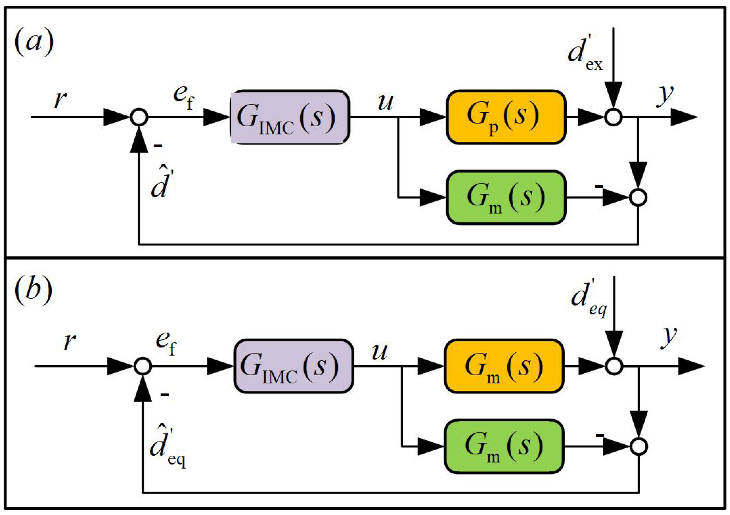
The structure of IMC is shown in Figure 2 ( G p ( s ) —actual controlled object; G m ( s ) —nominal model of the controlled object; G IMC ( s ) —internal model controller; d ex —external disturbance; r—target signal; d ^ —estimated value of the disturbance; d ^ eq —estimated value of the equivalent disturbance; e f —error; u—control input; y—system output). The following can be derived from Figure 2a:
e f = r d ^ = r d ex + u [ G m ( s ) G p ( s ) ]
Then, its equivalent structure can be described as in Figure 2b and d eq = d ex + u [ G p ( s ) G m ( s ) ] ; therefore,
e f = r d ^ eq = r d eq
Assumption 2.
The object model G p ( s ) is assumed to be a minimum phase system; at the same time, it is assumed that the relative error of the model is bounded and the limit value of the relative error is defined as
L m = sup t > 0 G p ( j ω ) G m ( j ω ) G m ( j ω )
Therefore, IMC is designed as follows:
G IMC ( s ) = G m 1 ( s ) Q ( s )
where Q ( s ) is a low-pass filter and generally designed in the following form [39]:
Q ( s ) = ( T s + 1 ) ε
In the formula, T is a positive real number and ε is a positive integer; the appropriate selection of ε can make G IMC ( s ) physically realizable. The necessary and sufficient condition for the controller to work stably [30] is
G IMC ( j ω ) G m ( j ω ) < L m 1 ω
In this case, the system output can be expressed as
y = r Q ( s ) + d eq ( 1 Q ( s ) )
It can be seen, from Equation (16), that, if | Q ( s ) | = 1 , y = r is satisfied; however, because of lim s 0 | Q ( s ) | = 1 , | Q ( s ) | < 1 is true except s = 0 . Therefore, when tracking is considered, there is a theoretical tracking error in IMC; the error is given as follows:
e th = r y = r ( 1 Q ( s ) )
When disturbance compensation is considered, the theoretical disturbance compensation provided by IMC is d ^ eq = d eq Q ( s ) . According to the block diagram in Figure 2b and Equation (5), d eq = d eq G m ( s ) can be derived; then,
d ^ eq = d eq Q ( s )
therefore, the disturbance compensation error d ˜ eq is
d ˜ eq = d eq d ^ eq = d eq ( 1 Q ( s ) )
Remark 3.
From the principle of IMC, it can be seen that IMC has strong disturbance compensation ability at low frequencies; therefore, IMC can be used to suppress part of low frequency disturbance, so as to reduce the switching gain of the SMC and bring chattering down. At the same time, IMC can also provide a certain amount of tracking and this is helpful to reduce the tracking error, which is analyzed below in the paper.

4.2. Design of Sliding Mode Controller Based on IMC (IM-SMC)

The state of a system can be decomposed into the sum of the states of two subsystems; one of the two subsystems can be designed at will and the other can be expressed as the difference between the original system and the designed subsystem [7]. In this paper, the state of the system was decomposed into IMC sub-state and SMC sub-state. If u I and u S represent the control inputs of IMC and SMC, respectively, the system can be expressed as follows:
x ˙ 1 = x 2 x ˙ 2 = a x 2 b x 1 + k ( u I + u S + d eq ) y = x 1
According to the analysis in Section 4.1, the IMC subsystem was designed as follows:
x ˙ I , 1 = x I , 2 x ˙ I , 2 = a x I , 2 b x I , 1 + k ( u I + d ^ eq ) y I = x I , 1
where x I , 1 and x I , 2 are sub-states of IMC and y I is the system output when IMC acts on the system. The new variable is defined as follows:
x S , 1 = Δ x 1 x I , 1 x S , 2 = Δ x 2 x I , 2 y S = Δ y y I
The SMC subsystem can be obtained from the above equations as
x ˙ S , 1 = x S , 2 x ˙ S , 2 = a x S , 2 b x S , 1 + k ( u S + d ˜ eq ) y S = x S , 1
where x S , 1 and x S , 2 are the control sub-states of SMC and y S is the system output when SMC acts on the system.
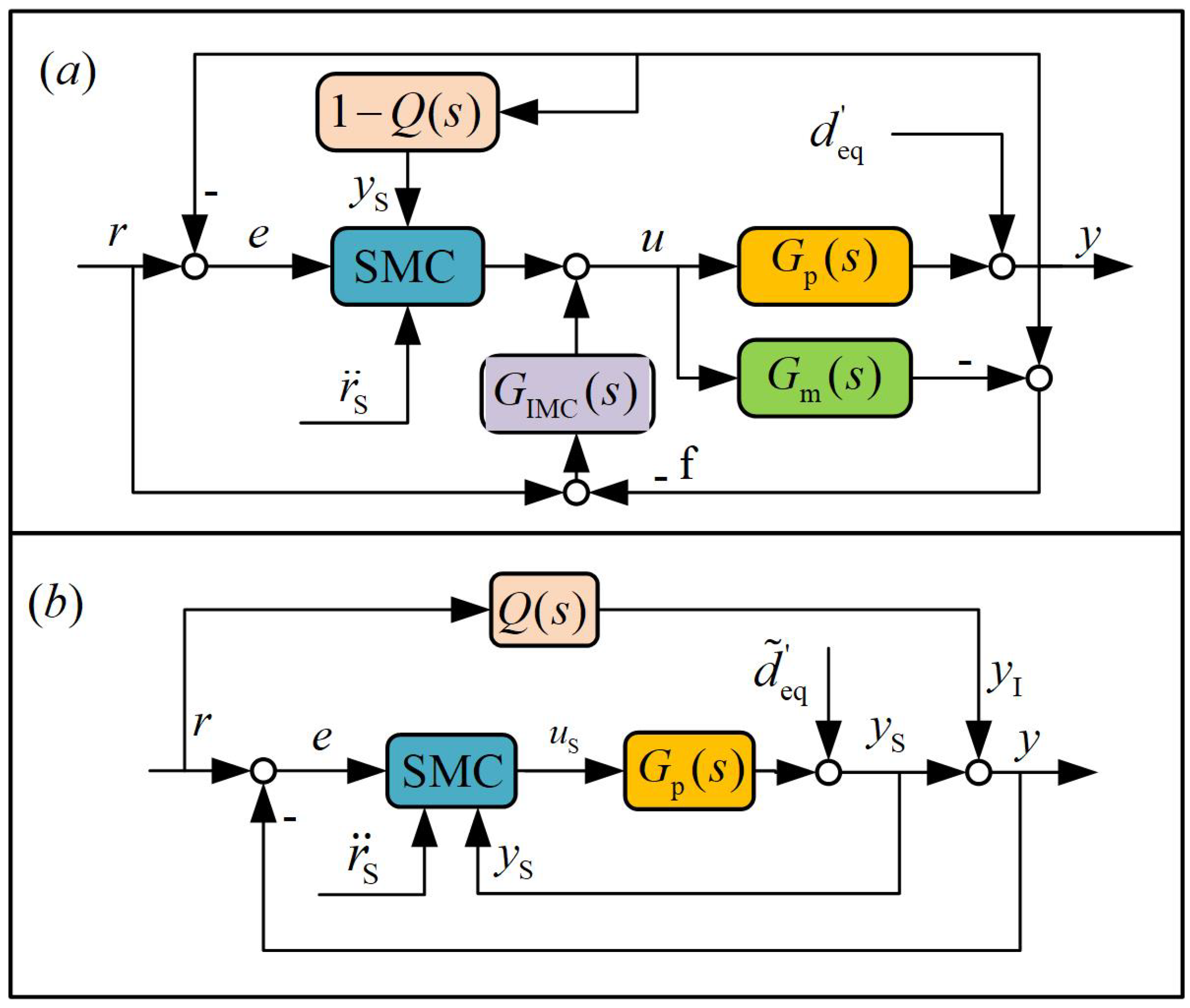
Based on the above decomposition, the controllers of the IMC subsystem and the SMC subsystem were designed respectively. In the controller design method proposed in this paper, the controller of the IMC subsystem was designed in the form of Formula (13) and the SMC subsystem controller was designed as the sliding mode controller. The control block diagram of the whole system is shown in Figure 3a and its equivalent structure is shown in Figure 3b. Next, the design details of the sliding mode controller are analyzed in combination with the block diagram.
The output of the IMC subsystem controller is given in Equation (16), which can be equivalent to the feedforward of the system from the input r to the output y and a disturbance compensation error, as shown in Figure 3b. In this case, the following can be derived:
y I = r Q ( s )
In order to enable the output to track the input, that is, y = r , the control task of the SMC is to obtain the output y S = y ( 1 Q ( s ) ) of the SMC subsystem; the tracking error of the system is rewritten as follows:
e = r y = r y I y S = r r Q ( s ) y S
Let r S = e th = r ( 1 Q ( s ) ) ; e = r S y S can be derived and the integral sliding mode surface is rewritten as:
σ = e ˙ + α e + β 0 t e d t
The designed sliding mode control law is
u S = k 1 ( r ¨ S + a y ˙ S + b y S + α e ˙ + β e + k c σ + η sgn ( σ ) ) .
Assumption 3.
Let us suppose that d ˜ eq is bounded and d ˜ e q * = sup t > 0 | d ˜ eq | is defined.
Remark 4.
Based on Assumption 3, from the sliding mode control principle, only η > k d ˜ eq * is needed and the initial state (outside the sliding mode surface) of the system converges to the sliding mode surface. At this time, in the low-frequency range, due to 1 Q ( s ) 0 , the gain of the switching term can be set smaller, so as to effectively reduce chattering.
Remark 5.
The mechanism whereby the SMC based on IMC can reduce tracking error is briefly explained. For a sliding mode controller with fixed parameters, the error rejection ratio (i.e., the ratio of the tracking error e to the reference input r) is determined for the reference input at a specific frequency. In the SMC based on IMC, IMC equivalently feeds forward a part of the tracking task r; therefore, for the SMC, it is equivalent to tracking a reference input r with a smaller amplitude. With the same parameters, due to the constant error suppression ratio, the tracking error is reduced accordingly.

4.3. Design of Improved Sliding Mode Controller Based on IMC (IM-ISMC)

As stated in Remark 4, under the condition of Assumption 3, as long as η is selected properly, chattering can be effectively reduced. However, in fact, the value of d ˜ eq * is not easy to obtain accurately. In addition, even if η is selected properly, there is a certain degree of chattering after the system reaches the sliding mode surface. Therefore, in this paper, a smooth unbounded function was used to replace the sign function; it is expressed in the form of sliding mode reaching law as follows:
σ ˙ = k c σ η σ n / m
where m and n are positive odd numbers ( m > n ) .
Formula (27) can be modified as follows:
u S = k 1 ( r ¨ S + a y ˙ S + b y S + α e ˙ + β e + k c σ + η σ n / m )
Considering the positive definite Lyapunov function V = σ 2 / 2 , the following can be derived from the above equation:
V ˙ = σ σ ˙ = σ ( r ¨ S y ¨ S + α e ˙ + β e ) = σ ( r ¨ S + a x S , 2 + b x S , 1 k u S k d ˜ e q + α e ˙ + β e ) = σ ( k c σ η σ n / m k d ˜ e q ) σ ( η σ n / m + k d ˜ e q )
Remark 6.
Because m and n are positive odd numbers, σ and σ n / m have the same sign. Based on Assumption 3, if only | η σ n / m | > k d ˜ eq * , then σ ( η σ n / m + k d ˜ eq ) > 0 ; then V ˙ 0 can be guaranteed and the system’s initial state outside the sliding mode surface converges to the sliding mode surface. According to the range characteristics of the σ n / m function, we know that it has a certain adaptive ability, so we do not need to know the value of d ˜ e q * accurately. Additionally, σ n / m is a continuous function; compared with the sign function, it can almost completely reduce chattering after the system reaches the sliding surface.

5. Application of Lifting Wavelet Threshold De-Noising

In order to reduce the influence of sensor measurement noise on the control performance of the control system and further reduce the tracking error, in this study, we propose to use lifting wavelet threshold de-noising (LWTD) for online de-noising of the collected sensor data. The lifting scheme-based wavelet transform [40] has the advantages of using a simple algorithm and fast calculation and it can meet the real-time requirements of the embedded system. Different from the traditional filtering method, wavelet threshold de-noising (WTD) can be used for de-noising in the whole frequency range. According to the WTD principle, the wavelet coefficients of useful signals and noise signals are different after the wavelet transform. The real signal generally exists in the high-amplitude wavelet coefficients, while the noise component generally exists in the low-amplitude wavelet coefficients [41]. By selecting an appropriate threshold and a threshold function and processing the high-frequency wavelet coefficients, the noise in the signal can be effectively removed. In order to meet the real-time online filtering requirements of the control system, the sliding window [42] can usually be used.

6. Simulation Analysis and Experiments

In this section, the method proposed in this paper is used for the ETS based on the FSM. To verify the superiority of the proposed method, firstly, the simulation results show that the proposed method can effectively reduce the tracking error and sliding mode chattering. Secondly, the tracking performance and disturbance suppression performance of the proposed method were verified by experiments. Finally, the feasibility and the effect of application of the LWTD in the control system were verified.

6.1. Experimental Apparatus

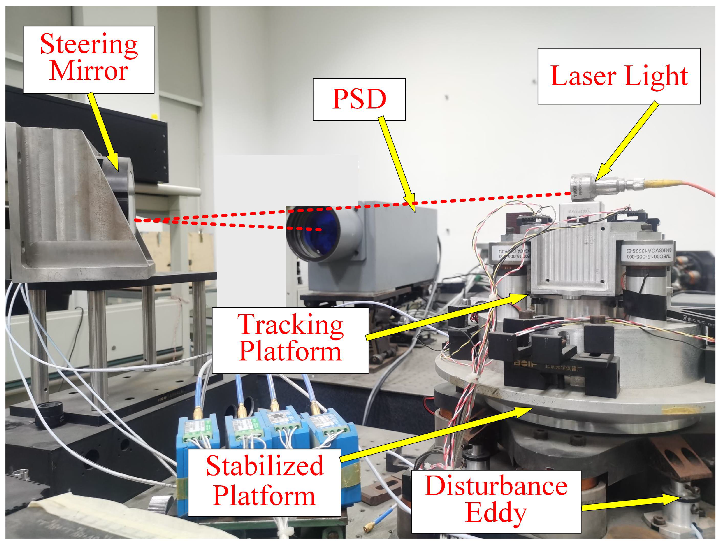
The electro-optical tracking device based on the FSM is usually a two-axis system. Because of the symmetry of the two axes, only one of them was used for analysis in the experiment. As shown in Figure 4, a device composed of two lapped systems was used to verify the controller designed in this paper. The upper platform was used to stabilize the laser light and the lower platform was used to simulate external disturbances. The stable platform was installed on the disturbance platform and the laser head was directly fixed on the top of the stabilized platform to simulate the moving target. Both platforms were driven by voice coil motors. On the disturbed platform, the eddy current sensors were used to measure the disturbance angle of the platform. The position response of the stabilized platform was directly obtained by the PSD. The employed control board in this system was PC104LX3073, on which the real-time operating system VxWorks was installed. In the experiment, the sampling rates of all the sample sensors were 5000 Hz and the operating frequency of the controller was set to 1000 Hz.
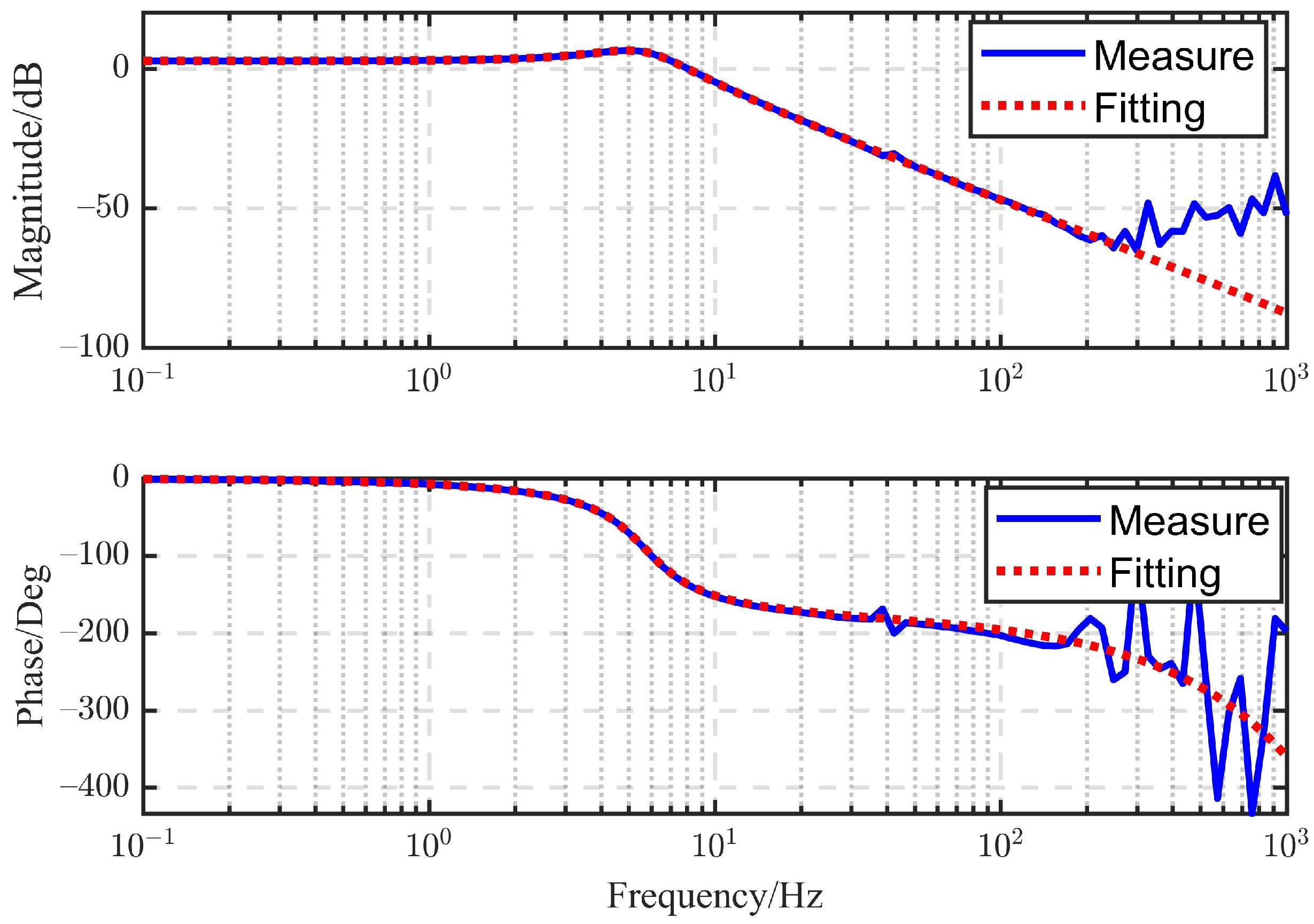
The position open-loop Bode diagram of the FSM system was obtained by sinusoidal frequency sweep, as shown in Figure 5. After fitting, the position open-loop transfer function was obtained as follows:
G m ( s ) = 1770.0622 s 2 + 24.7118 s + 1282.6538
That is, a = 24.7118 , b = 1282.6538 and k = 1770.0622 .

6.2. Simulation Analysis

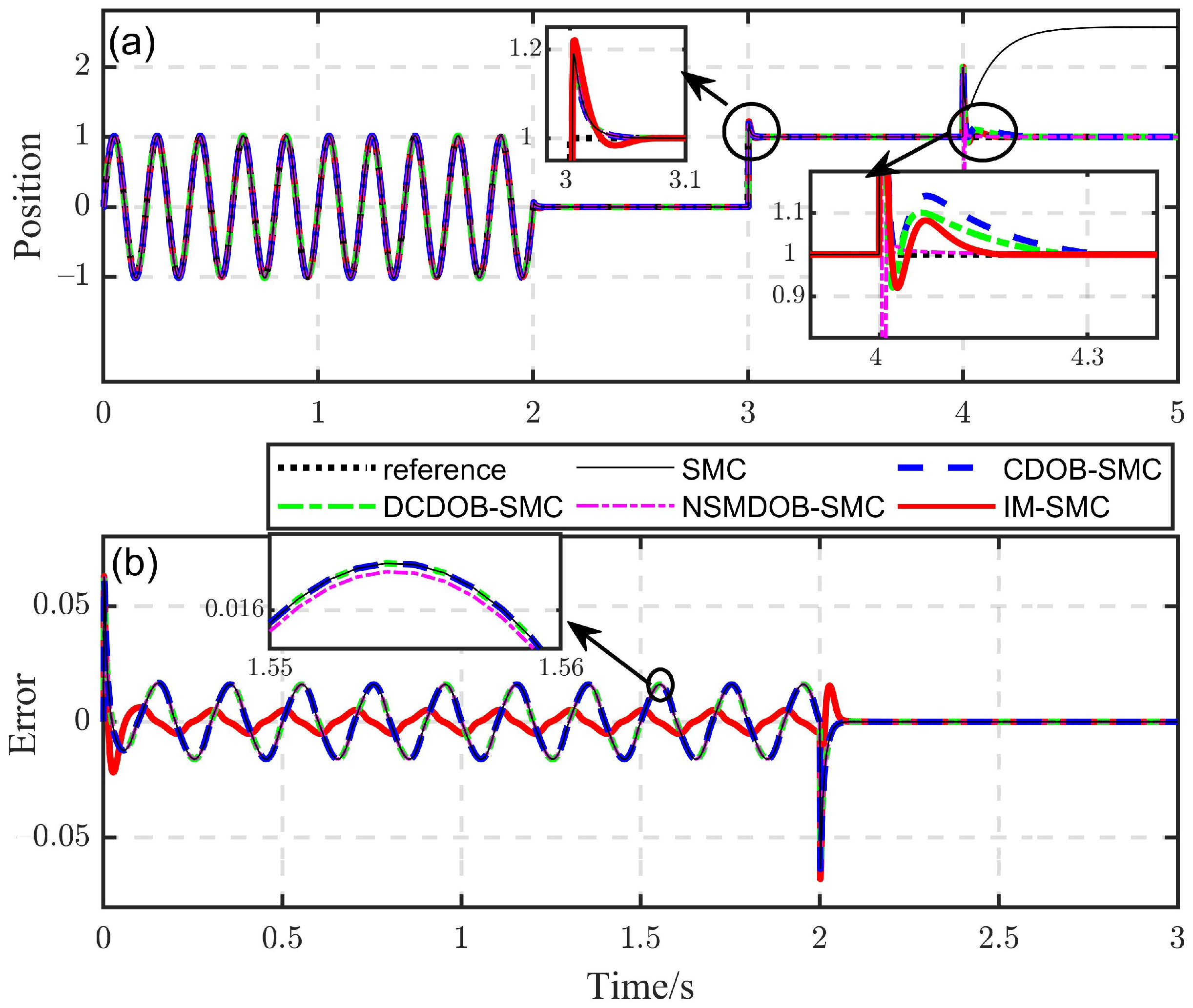
As mentioned in Section 1, the DOB cannot be used for tracking, but IMC can be used to track independently, so the IMC-based SMC was compensated by IMC with a part of the tracking amount; therefore, the tracking burden of the SMC was reduced and, consequently, the tracking error could be reduced. Next, the performance difference between the SMC based on the DOB and the SMC based on IMC was verified by comparative simulation. To show the superiority of the proposed algorithm, three different DOBs were designed and are presented in this subsection; they were: the conventional DOB (CDOB) [43], the dual-compensator DOB (DCDOB) [44] and the novel sliding mode DOB (NSMDOB) [7]. To ensure the relative fairness of the comparison, the SMC with the same parameters was invoked as the closed-loop controller. The related parameters are given in Table 1. The meaning of the parameters not explained in the table is consistent with the original reference. Therefore, the SMC, CDOB-based SMC (CDOB-SMC), DCDOB-based SMC (DCDOB-SMC), NSMDOB-based SMC (NSMDOB-SMC) and IMC-based SMC (IM-SMC) were used for comparison. The simulation verification was carried out via MATLAB/Simulink software. The simulation step size was set to 0.001 s and the solver was set to the Euler method. The simulation results are shown in Figure 6.
In Figure 6a, a sinusoidal input with a frequency ( f = 5 ) was given in the first two seconds, a step reference was given from the third second and a given external disturbance ( d e x = 1 ) was applied at the fourth second. The tracking error of the first three seconds is shown in Figure 6b. It can be seen that the control methods had a good ability to suppress disturbance except for the SMC method. Although the NSMDOB-SMC method took the shortest recovery time after disturbance, the initial fluctuation was the largest. Compared with the other three DOB-based methods, the IM-SMC method had better comprehensive performance. Compared with the SMC method, the DOB-based methods had little contribution to improving the steady-state tracking accuracy. The dynamic response of the IM-SMC was slightly worse than that of other methods, but the IM-SMC method obviously had a smaller sinusoidal tracking error.
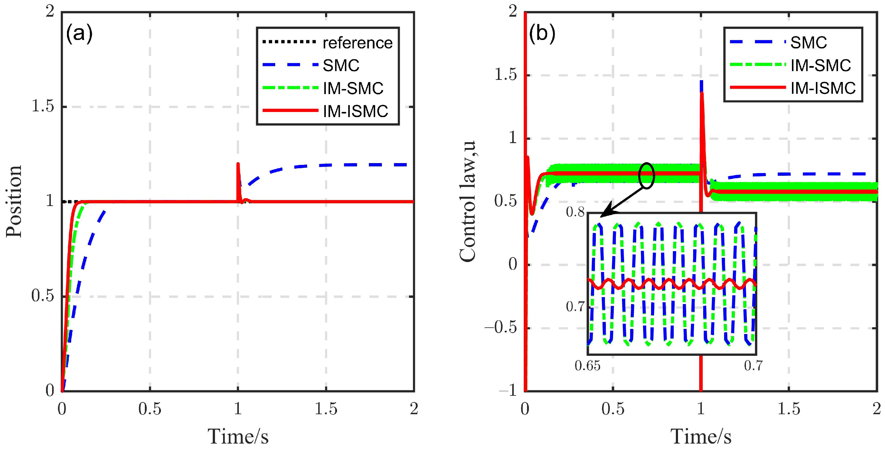
As stated in Remark 4, the proposed method can be used to reduce chattering by setting a relatively small switching gain. As described in Remark 6, the designed reaching law can further reduce chattering. Next, we continued to verify this feature through simulation research. The simulation was carried out in two cases. In Case I, the system was considered to have external disturbance only and, in Case II, the system was considered to have model uncertainty. In order to make a comparative study, three different control methods were used. Some control parameters of different control methods are listed in Table 2.
Case I:
Firstly, η = 100 was uniformly selected in the three control methods and an external step disturbance ( d e x = 0.2 ) was added at t = 1 s; the result is shown in Figure 7. It can be seen that both the SMC and IM-SMC produced the same chattering when the system reached the sliding mode surface before the disturbance was added, while the IM-ISMC almost did not produce chattering because of use of the smooth function. After the disturbance was added, the SMC could not suppress the disturbance and the system could also not reach the sliding surface because the switching gain was not large enough. However, most of the disturbance of the IM-SMC was compensated, so the system reached the sliding mode surface, chattering was generated and the IM-ISMC still performed well.
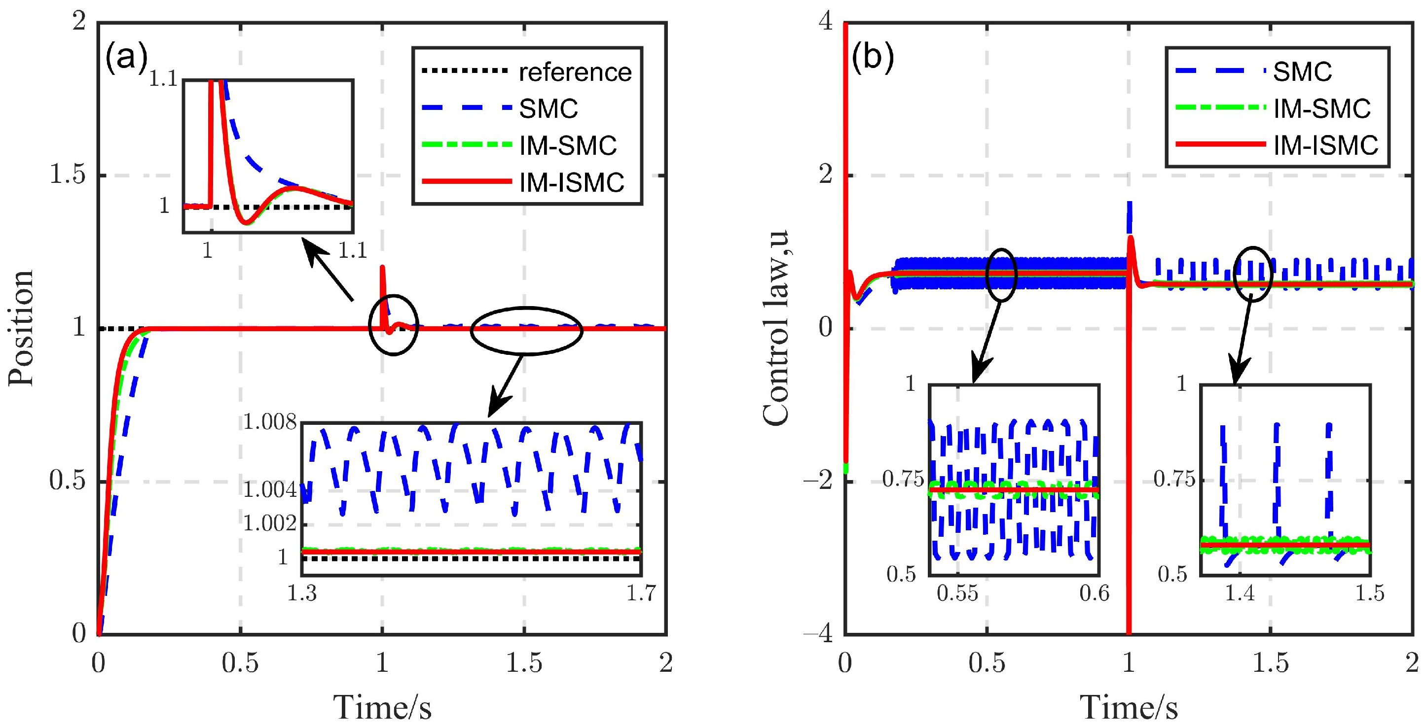
Because the external disturbance of the IM-SMC can be compensated by IMC, reducing the switching gain does not affect the disturbance suppression performance of the system. Therefore, chattering can be reduced by decreasing the switching gain. On the contrary, in order to suppress external disturbances, the switching gain of SMC should be increased. By increasing the switching gain of the SMC to η = 280 and reducing the switching gain of the other two controllers to η = 28 , the simulation results were obtained, as shown in Figure 8. At this time, all three methods could suppress the external disturbance, but the SMC caused more severe chattering, while chattering was reduced by using the IM-SMC and there was almost no chattering when using the IM-ISMC. It can be seen, from Figure 8a, that the IM-SMC and IM-ISMC caused a smaller static error than the SMC.
Case II:
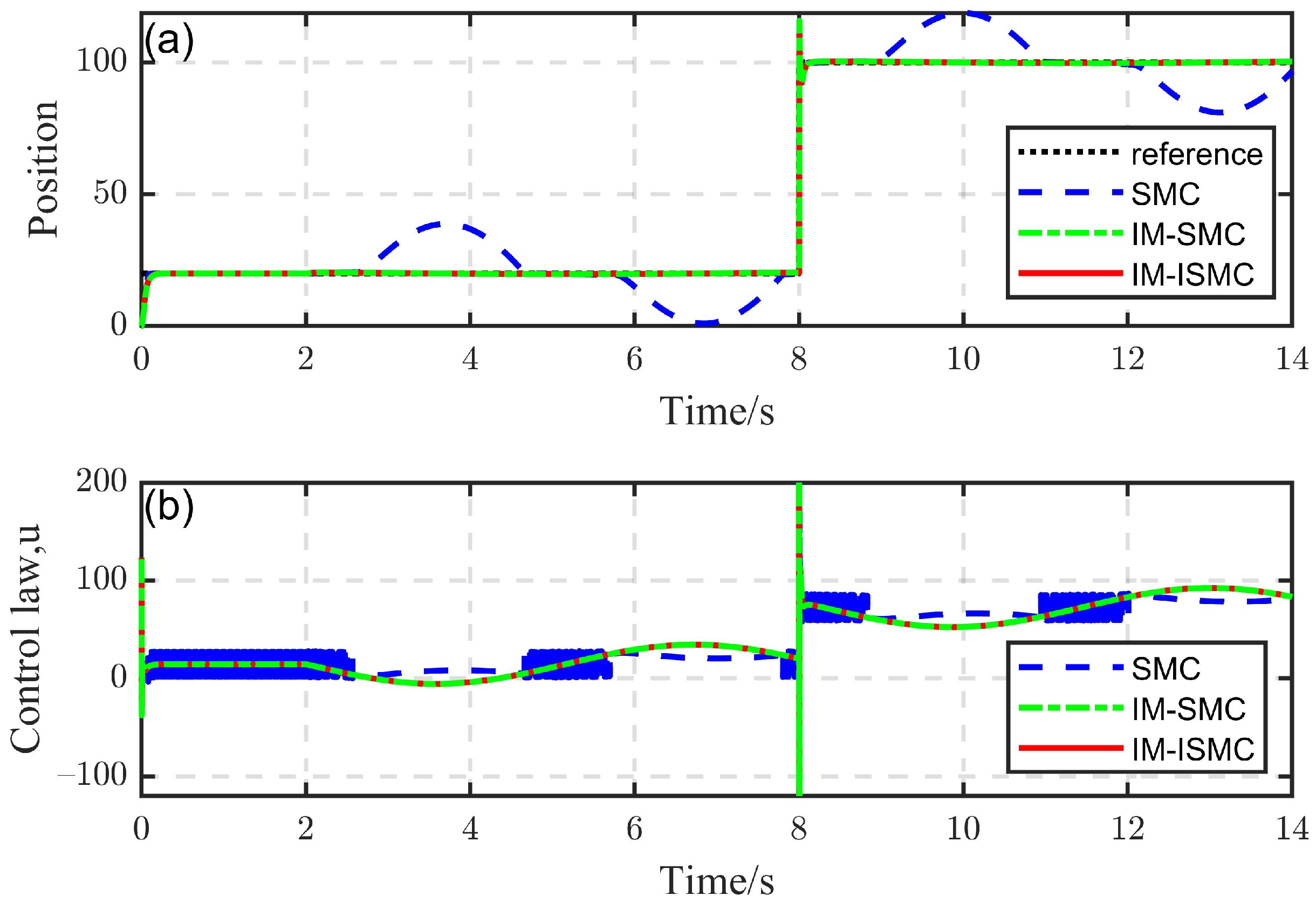
Figure 9 shows the simulation results of the three control methods when there were model uncertainties. At the 2nd second in the system operation process, different degrees of model uncertainties were added, namely, δ a = 0.5 sin ( t 2 ) , δ b = 10 sin ( t 2 ) and δ k = 20 sin ( t 2 ) and the switching gain of the SMC was set to η = 20 , 000 , while the switching gain of the other two control methods was still set to η = 28 . It can be seen that the switching gain of the SMC was still not large enough in the period when the blue curve is convex, which means it could not completely suppress the model uncertainty. However, in the period when the model uncertainties were completely suppressed, the switching gain was too large, leading to chattering of the control law.
Therefore, with the traditional SMC, when the model uncertainties changed, it was impossible to choose a suitable fixed switching gain to ensure that disturbance and model uncertainties were effectively suppressed and ensure that chattering did not occur. In contrast, the IM-SMC and IM-ISMC not only effectively suppressed the model uncertainties, but also did not produce severe chattering. This shows the availability of the controller designed in this study.

6.3. Experiment Analysis

In this section, the experimental effect of the IM-ISMC control method proposed in this paper was verified by experiments. In the experiments, the controller parameters were the same as those in Table 2 and the switching gain of η = 200 was set uniformly. In Section 6.3.1 and Section 6.3.2, the problem of sensor noise is not considered temporarily and the results of lifting wavelet de-noising are shown in Section 6.3.3.

6.3.1. Tracking Performance

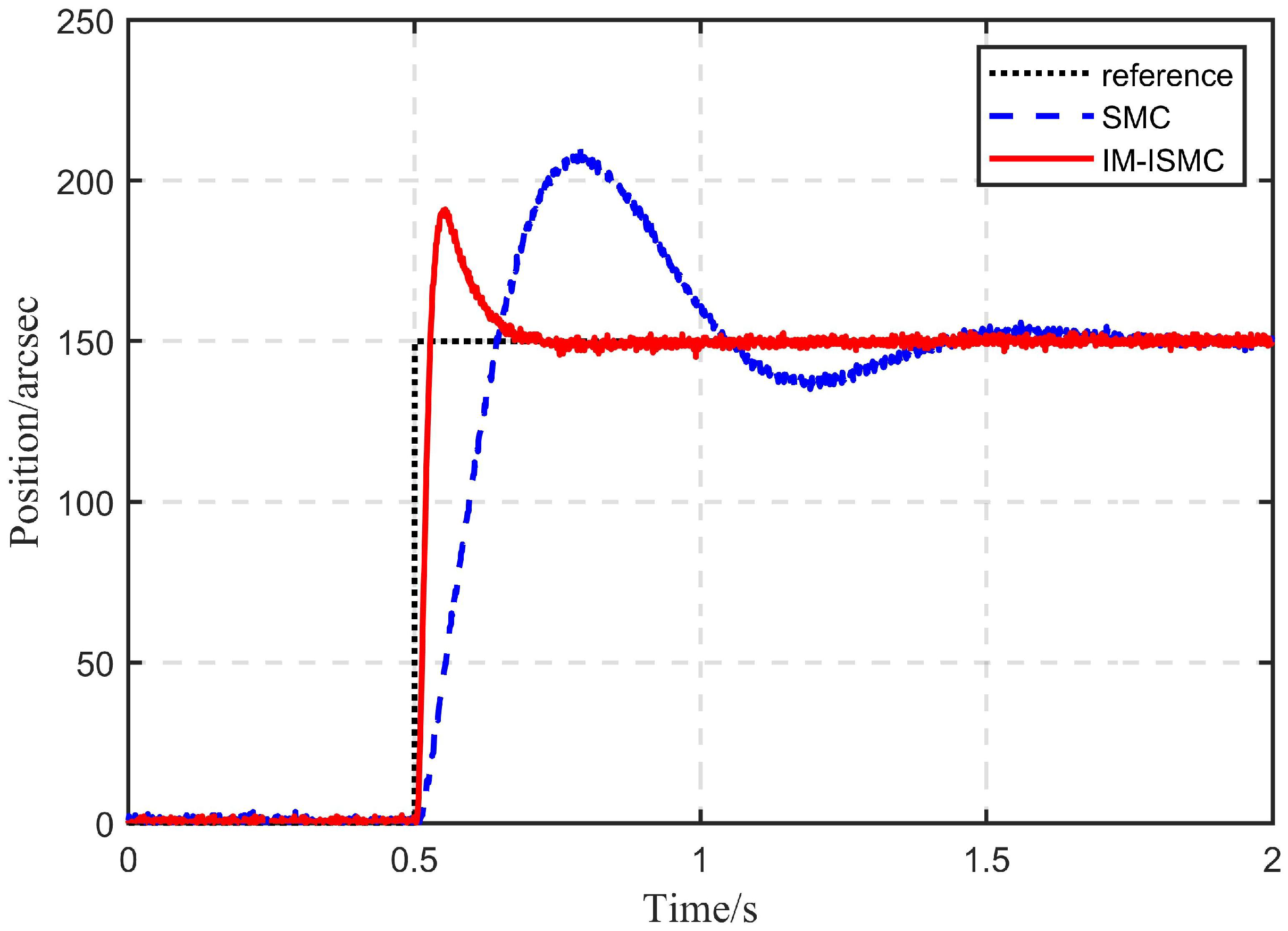
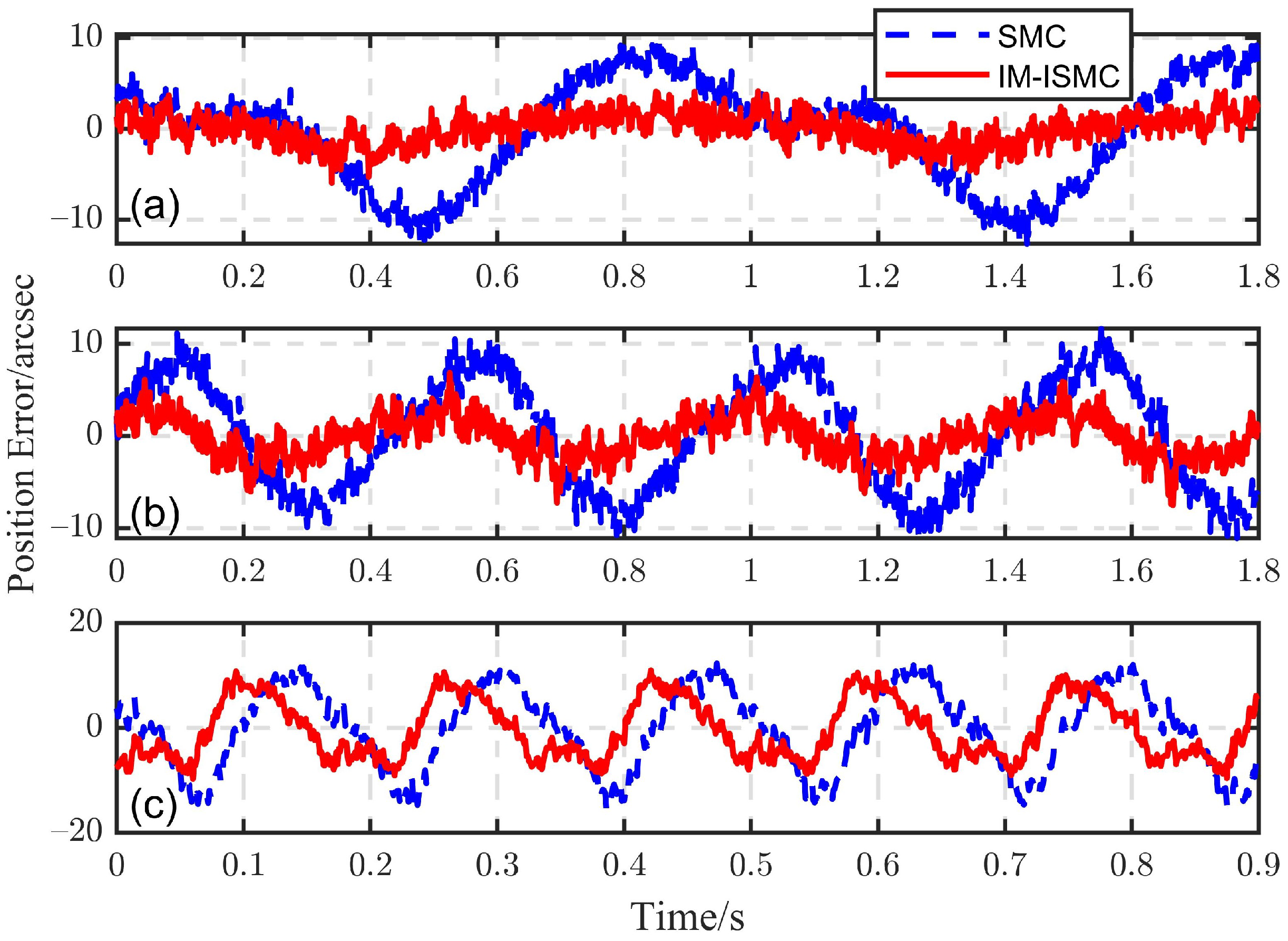
The tracking ability of the IM-ISMC structure proposed in this paper was verified without adding disturbance in this experiment. The tracking performance was measured by comparing the effect of tracking a given step signal and sinusoidal signals with different frequencies. In order to show the advantages of the IM-ISMC method, its results were compared with those of the SMC method. Firstly, for the given step signal, the tracking result is shown in Figure 10. It can be seen that the IM-ISMC method had better dynamic performance. Then, sinusoidal signals with different frequencies were considered and the FSM usually worked at 1 5 Hz. Therefore, Figure 11a–c gives the tracking errors of sinusoidal signals with frequencies of 1 Hz, 2 Hz and 6 Hz and amplitudes of 500 arcsec. It can be seen that the tracking error obtained by the IM-ISMC method was obviously smaller than that obtained by the SMC method.

6.3.2. Disturbance Suppression Performance

In order to verify the actual disturbance rejection performance of the proposed method, the tracking value of the tracking platform was set as r = 0 arcsec and the position response of the tracking platform was recorded when applying an external disturbance to the lower stabilized platform. The results of the SMC method were also compared.
Figure 12a,b, respectively, shows the experimental results under step disturbance and compound sinusoidal disturbance. Because the disturbance was added by manual operation, the disturbance adding time in the two control methods (Figure 12a shows that disturbance was added at about 0.5 s, while Figure 12b shows that disturbance was added at about 1 s) was not exactly the same. The amplitude of step disturbance was 500 arcsec and the compound sinusoidal disturbance was composed of sinusoidal signals with amplitudes of 200, 100 and 50 arcsec and frequencies of 0.5 Hz, 3 Hz and 6 Hz, respectively. It can be seen that the IM-ISMC method had good disturbance rejection ability under the same switching gain. Increasing the switching gain of SMC allowed us to obtain better disturbance rejection performance, but, as shown in the simulation results (Figure 8), an excessive switching gain η caused large amplitude chattering and increase in the load on the driver, which is adverse to the actual operation. At the same time, we should pay attention to the SMC result of Figure 12a. In this case, the value η was less than the upper bound of the disturbance. Theoretically, the disturbance suppression ability of the SMC is very weak. The result in the figure was caused by the attenuation effect of the stabilized platform itself on the disturbance.

6.3.3. The Effect of LWTD

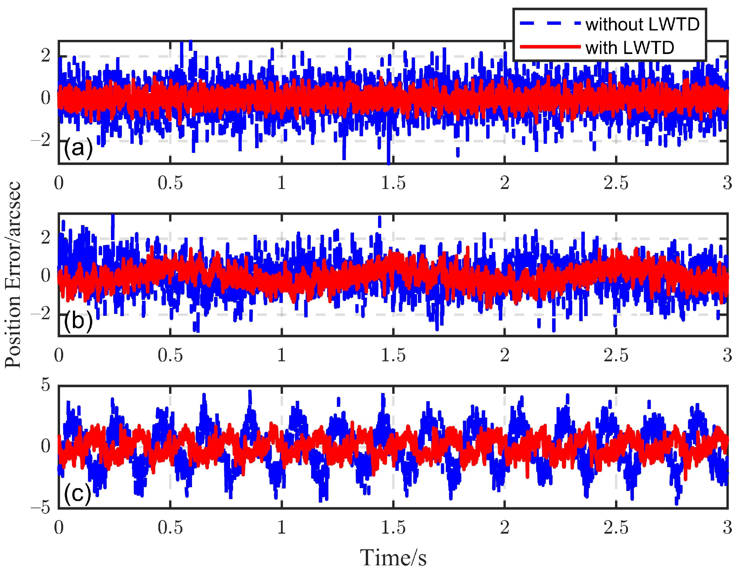
To verify the feasibility and the practical application effect of the LWTD, the tracking results obtained by using the IM-ISMC control structure were compared before and after adding the LWTD. In the experiment, the Haar wavelet was used for the wavelet transform, the general threshold function and the soft threshold method were used to calculate the threshold value and process wavelet coefficients, respectively, and data symmetric continuation was used to weaken the boundary distortion caused by the wavelet transform. In addition, the length of the sliding window was set to 16 and the number of decomposition layers was set to 3. The experimental results are shown in Figure 13. Figure 13a–c shows the tracking errors of sinusoidal signals with frequencies of 0 Hz, 1 Hz and 5 Hz and the amplitude of 100 arcsec, respectively. It can be seen that the tracking error could be significantly reduced by adding the LWTD, that is, using the output signal after LWTD, as the feedback could effectively reduce the tracking error, which proves that the LWTD had a good de-noising effect and could effectively recover the actual useful signal from the noise. Besides, through experiments, we also verified that the LWTD could be used in the control system.

7. Conclusions

To improve the tracking accuracy of the ETS based on a moving platform, a design of the SMC scheme based on IMC is proposed. Meanwhile, a new sliding mode reaching law is proposed. The numerical simulation and experimental results show that the proposed method could achieve strong disturbance rejection effects with a small switching gain and had smaller chattering than the traditional SMC. At the same time, the tracking error of the SMC could be reduced. Furthermore, the LWTD was integrated into the control structure to remove the measurement noise and further reduce the tracking error of the system. The experimental results show that the method is feasible and effective in the control system. Therefore, the method designed in this paper provides a practical control scheme for the ETS based on a moving platform to achieve high-precision tracking.
In future research, the output time delay will be considered because of its widespread existence in the ETS. Moreover, the non-singular fast terminal SMC can be used to replace the traditional SMC to achieve finite time convergence.

Author Contributions

Conceptualization, B.Z.; methodology, Y.M.; software, B.Z. and K.N; validation, B.Z. and K.N.; formal analysis, Y.M.; investigation, B.Z.; resources, X.C.; data curation, K.N.; writing—original draft preparation, B.Z.; writing—review and editing, K.N.; visualization, B.Z.; supervision, X.C.; project administration, X.C.; All authors have read and agreed to the published version of the manuscript.

Funding

This research study was funded by the National Natural Science Foundation of China, grant numbers 61733012 and 61905253, and the National Key R&D Program of China, grant number 2017YFB1103002.

Institutional Review Board Statement

Not applicable.

Informed Consent Statement

Not applicable.

Data Availability Statement

No new data were created or analyzed in this study. Data sharing is not applicable to this article.

Conflicts of Interest

The authors declare no conflict of interest.

Abbreviations

The following abbreviations are used in this manuscript:
ETSElectro-optical tracking system
SMCSliding mode control
IMCInternal model control
DOBDisturbance observer
CDOBConventional disturbance observer
DCDOBDual-compensator disturbance observer
NSMDOBNovel sliding mode disturbance observer
CDOB-SMCSMC based on CDOB
DCDOB-SMCSMC based on DCDOB
NSMDOB-SMCSMC based on NSMDOB
IM-SMCSMC based on IMC
IM-ISMCImproved SMC based on IMC
UAVUnmanned Aerial Vehicle
FSMFast steering mirror
EMFElectromagnetic forming
WTDWavelet threshold de-noising
LWTDLifting wavelet threshold de-noising
PSDPosition sensitive detector

References

  1. Kim, J.; Lee, D.; Cho, K.; Jo, S.; Kim, J.; Min, C.; Han, D.; Cho, S. Development of an electro-optical system for small UAV. Aerosp. Sci. Technol. 2010, 14, 505–511. [Google Scholar] [CrossRef]
  2. Boroson, D.; Robinson, B.; Burianek, D.; Murphy, D.; Biswas, A. Overview and Status of the Lunar Laser Communications Demonstration. Proc. SPIE Int. Soc. Opt. Eng. 2012, 8246, 7–30. [Google Scholar]
  3. Bi, Z.; Tian, Z.; Tao, L.; Fu, S. Study on Shipborne Video Electro-Optical Tracking System Based on FPGA; Springer: Berlin/Heidelberg, Germany, 2016. [Google Scholar]
  4. Tian, J.; Yang, W.; Peng, Z.; Tang, T. Inertial sensor-based multiloop control of fast steering mirror for line of sight stabilization. Opt. Eng. 2016, 55, 111602. [Google Scholar] [CrossRef] [Green Version]
  5. Deng, C.; Tang, T.; Mao, Y.; Ren, G. Enhanced Disturbance Observer Based on Acceleration Measurement for Fast Steering Mirror Systems. IEEE Photonics J. 2017, 9, 1–11. [Google Scholar]
  6. Zhou, X.; Li, X. A Finite-Time Robust Adaptive Sliding Mode Control for Electro-Optical Targeting System with Friction Compensation. IEEE Access 2019, 7, 166318–166328. [Google Scholar]
  7. Ren, Y.; Tian, D.; Yu, D. Research of NSMDOB-Based Compound Control for Photoelectric Tracking Platform. IEEE Access 2020, 8, 62650–62659. [Google Scholar] [CrossRef]
  8. Zhou, X.; Li, X. Trajectory tracking control for electro-optical tracking system based on fractional-order sliding mode controller with super-twisting extended state observer. ISA Trans. 2021, 117, 85–95. [Google Scholar] [CrossRef] [PubMed]
  9. Yu, X.; Kaynak, O. Sliding-Mode Control With Soft Computing: A Survey. IEEE Trans. Ind. Electron. 2009, 56, 3275–3285. [Google Scholar]
  10. Zhang, G.; Wang, Y.; Wang, J.; Chen, J.; Qian, D. Disturbance observer—Based super-twisting sliding mode control for formation tracking of multi-agent mobile robots. Meas. Control 2020, 53, 908–921. [Google Scholar] [CrossRef]
  11. Cheng, X.; Liu, H.; Lu, W. Chattering-Suppressed Sliding Mode Control for Flexible-Joint Robot Manipulators. Actuators 2021, 10, 288. [Google Scholar] [CrossRef]
  12. Wang, M.; Wang, Y.; Yang, R.; Fu, Y.; Zhu, D. A Sliding Mode Control Strategy for an ElectroHydrostatic Actuator with Damping Variable Sliding Surface. Actuators 2021, 10, 3. [Google Scholar] [CrossRef]
  13. Qiao, Q.; Zhong, M.; Ren, W.; Duan, Q.; Chen, X.; Mao, Y. Sliding mode control of the photoelectric servo platform with input saturation. Laser Technol. 2020, 44, 429–435. [Google Scholar]
  14. Ren, Y.; Liu, Z.; Liu, X.; Zhang, Y. A Chattering Free Discrete-Time Global Sliding Mode Controller for Optoelectronic Tracking System. Math. Probl. Eng. 2013, 1–8. [Google Scholar] [CrossRef]
  15. Wei, Y.; Ma, J.; Jing, X. Tracking control strategy for the optoelectronic system on the flexible suspended platform based on backstepping method. J. Proc. SPIE Int. Soc. Opt. Eng. 2012, 8418, 8418. [Google Scholar]
  16. Ren, Y.; Liu, Z.H.; Zhou, R. Adaptive Terminal Sliding Mode Control of Opto-Electronic Stabilized Platform Based on Acceleration Feedback. Adv. Mater. Res. 2012, 468-471, 523–528. [Google Scholar] [CrossRef]
  17. Lu, Y. Sliding-Mode Disturbance Observer with Switching-Gain Adaptation and Its Application to Optical Disk Drives. IEEE Trans. Ind. Electron. 2009, 56, 3743–3750. [Google Scholar]
  18. Zhang, M. Finite-time model-free trajectory tracking control for overhead cranes subject to model uncertainties, parameter variations and external disturbances. Trans. Inst. Meas. Control 2019, 41, 3516–3525. [Google Scholar] [CrossRef]
  19. Yang, J.; Li, S.; Yu, X. Sliding-Mode Control for Systems with Mismatched Uncertainties via a Disturbance Observer. IEEE Trans. Ind. Electron. 2013, 60, 160–169. [Google Scholar] [CrossRef]
  20. Seungmin, B.; Jaemin, B.; Soohee, H. An Adaptive Sliding Mode Control with Effective Switching Gain Tuning Near the Sliding Surface. IEEE Access 2019, 7, 15563–15572. [Google Scholar]
  21. Goel, A.; Mobayen, S. Adaptive nonsingular proportional–integral–derivative-type terminal sliding mode tracker based on rapid reaching law for nonlinear systems. J. Vib. Control 2020, 27, 2669–2685. [Google Scholar] [CrossRef]
  22. Alattas, K.A.; Mobayen, S.; Din, S.U.; Asad, J.H.; Fekih, A.; Assawinchaichote, W.; Vu, M.T. Design of a Non-Singular Adaptive Integral-Type Finite Time Tracking Control for Nonlinear Systems with External Disturbances. IEEE Access 2021, 9, 102091–102103. [Google Scholar] [CrossRef]
  23. Karami, H.; Alattas, K.A.; Mobayen, S.; Fekih, A. Adaptive Integral-Type Terminal Sliding Mode Tracker Based on Active Disturbance Rejection for Uncertain Nonlinear Robotic Systems with Input Saturation. IEEE Access 2021, 9, 129528–129538. [Google Scholar] [CrossRef]
  24. Saghafinia, A.; Ping, H.; Uddin, M.; Gaeid, K. Adaptive Fuzzy Sliding-Mode Control into Chattering-Free IM Drive. Ind. Appl. IEEE Trans. 2015, 51, 692–701. [Google Scholar] [CrossRef]
  25. Gong, C.; Hu, Y.; Gao, J.; Wang, Y.; Yan, L. An Improved Delay-Suppressed Sliding Mode Observer for Sensorless Vector-Controlled PMSM. IEEE Trans. Ind. Electron. 2020, 67, 5913–5923. [Google Scholar] [CrossRef]
  26. Humaidi, A.J.; Hasan, A.F. Particle swarm optimization—Based adaptive super-twisting sliding mode control design for 2-degree-of-freedom helicopter. Meas. Control-Lond.-Inst. Meas. Control 2019, 52, 1403–1419. [Google Scholar] [CrossRef] [Green Version]
  27. Sui, S.; Zhao, T. Active disturbance rejection control for optoelectronic stabilized platform based on adaptive fuzzy sliding mode control. ISA Trans. 2021. [Google Scholar] [CrossRef]
  28. Giap, V.; Huang, S. Effectiveness of fuzzy sliding mode control boundary layer based on uncertainty and disturbance compensator on suspension active magnetic bearing system. Meas. Control 2020, 53, 934–942. [Google Scholar] [CrossRef] [Green Version]
  29. Lu, Y.; Tan, C.; Ge, W.; Li, B.; Lu, J. Improved Sliding Mode-Active Disturbance Rejection Control of Electromagnetic Linear Actuator for Direct-Drive System. Actuators 2021, 10, 138. [Google Scholar] [CrossRef]
  30. Morari, M. Robust Process Control. Chem. Eng. Res. Des. 1991, 65, 462–479. [Google Scholar]
  31. Xu, Q. Continuous Integral Terminal Third-Order Sliding Mode Motion Control for Piezoelectric Nanopositioning System. IEEE/ASME Trans. Mechatron. 2017, 22, 1828–1838. [Google Scholar] [CrossRef]
  32. Nguyen, M.H.; Dao, H.V.; Ahn, K.K. Active Disturbance Rejection Control for Position Tracking of Electro-Hydraulic Servo Systems under Modeling Uncertainty and External Load. Actuators 2021, 10, 20. [Google Scholar] [CrossRef]
  33. Ryszard, S.G. Sliding Mode versus Parallel Compensator Based Control under Measurement Noise. IFAC Proc. Vol. 2014, 47, 4601–4606. [Google Scholar]
  34. Sun, J.; Pu, Z.; Yi, J.; Liu, Z. Fixed-Time Control with Uncertainty and Measurement Noise Suppression for Hypersonic Vehicles via Augmented Sliding Mode Observers. IEEE Trans. Ind. Inform. 2020, 16, 1192–1203. [Google Scholar] [CrossRef]
  35. Mitsantisuk, C. Estimation of Action/Reaction Forces for the Bilateral Control Using Kalman Filter. IEEE Trans. Ind. Electron. 2012, 59, 4383–4393. [Google Scholar] [CrossRef]
  36. Yu, X.; Li, J.; Xu, J. Nonlinear filtering in unknown measurement noise and target tracking system by variational Bayesian inference. Aerosp. Sci. Technol. 2019, 84, 37–55. [Google Scholar] [CrossRef]
  37. Duan, Q.; Mao, Y.; Zhang, H.; Xue, W. Add-on integration module-based proportional-integration-derivative control for higher precision electro-optical tracking system. Trans. Inst. Meas. Control 2021, 43, 1347–1362. [Google Scholar] [CrossRef]
  38. She, J.H.; Xin, X.; Ohyama, Y. Estimation of Equivalent Input Disturbance Improves Vehicular Steering Control. IEEE Trans. Veh. Technol. 2007, 56, 3722–3731. [Google Scholar] [CrossRef]
  39. Abe, N.; Yamanaka, K. Smith predictor control and internal model control—A tutorial. In Proceedings of the SICE 2003 Annual Conference (IEEE Cat. No.03TH8734), Fukui, Japan, 4–6 August 2003; Volume 2, pp. 1383–1387. [Google Scholar]
  40. Sweldens, W. The Lifting Scheme: A Custom-Design Construction of Biorthogonal Wavelets. Appl. Comput. Harmon. Anal. 1996, 3, 186–200. [Google Scholar] [CrossRef] [Green Version]
  41. Srivastava, M.; Anderson, C.L.; Freed, J.H. A New Wavelet Denoising Method for Selecting Decomposition Levels and Noise Thresholds. IEEE Access Pract. Innov. Open Solut. 2016, 4, 3862–3877. [Google Scholar] [CrossRef]
  42. Xia, R.; Meng, K.; Qian, F.; Wang, Z.L. Online Wavelet Denoising via a Moving Window. Acta Autom. Sin. 2007, 33, 897–901. [Google Scholar] [CrossRef]
  43. Li, S.; Yang, J.; Chen, W.H.; Chen, X. Disturbance Observer-Based Control: Methods and Applications; CRC Press: Boca Raton, FL, USA, 2014. [Google Scholar]
  44. Deng, J.; Xue, W.; Zhou, X.; Mao, Y. On disturbance rejection control for inertial stabilization of long-distance laser positioning with movable platform. Meas. Control 2020, 53, 1203–1217. [Google Scholar] [CrossRef]
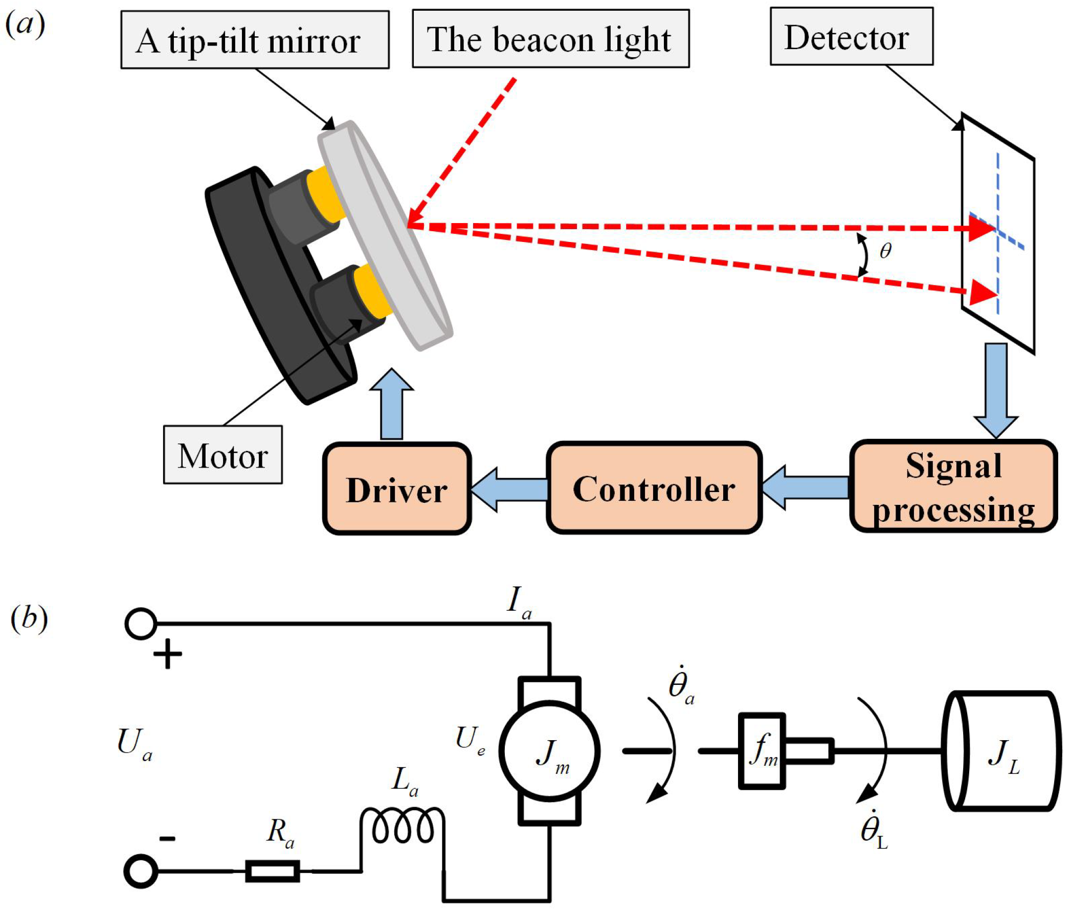
Figure 1. (a) Schematic diagram of ETS. (b) Physical model structure of the controlled plant.
Actuators 11 00016 g001
Figure 2. (a) Block diagram of IMC principle. (b) Equivalent block diagram of IMC.
Actuators 11 00016 g002
Figure 3. (a) Block diagram of the structure of IM-SMC. (b) Equivalent block diagram of IM-SMC.
Actuators 11 00016 g003
Figure 4. Experimental apparatus.
Actuators 11 00016 g004
Figure 5. Bode diagram of experimental apparatus.
Actuators 11 00016 g005
Figure 6. Performance comparison of five different control methods: (a) Position response, (b) Position tracking error.
Actuators 11 00016 g006
Figure 7. The effect of chattering reduction ( η S M C = η I M S M C = η I M I S M C = 100 ): (a) Position response, (b) Control law.
Actuators 11 00016 g007
Figure 8. The effect of chattering reduction ( η S M C = 280 and η I M S M C = η I M I S M C = 28 ): (a) Position response, (b) Control law.
Actuators 11 00016 g008
Figure 9. The effect of model uncertainty ( η S M C = 20 , 000 and η I M S M C = η I M I S M C = 28 ): (a) Position response, (b) Control law.
Actuators 11 00016 g009
Figure 10. Online tracking errors with step reference.
Actuators 11 00016 g010
Figure 11. Online tracking errors with sinusoidal reference: (a) 1 Hz, (b) 2 Hz and (c) 6 Hz.
Actuators 11 00016 g011
Figure 12. Online disturbance suppression: (a) step disturbance; (b) sinusoidal disturbance.
Actuators 11 00016 g012
Figure 13. Comparison of tracking errors before and after using LWTD: (a) 0 Hz, (b) 1 Hz and (c) 5 Hz.
Actuators 11 00016 g013
Table 1. The design parameters of different methods.
MethondsParameters
SMC α = 100 , β = 1 , k c = 8 , η = 20 .
IMC ε = 2 , T = 0.01 .
CDOB Q ( s ) = 1 / ( τ s + 1 ) 2 , τ = 0.01 .
DCDOB C f 1 = k 1 ( s 2 + a s + b ) / [ k ( s + n 1 ) 2 ] , C f 2 = k 2 ( s 2 + a s + b ) / [ k ( s + n 2 ) 2 ] , n 1 = 150 , n 2 = 100 , k 1 = k 2 = 10 , 000 .
NSMDOB A = 0 1 b a , B = 0 k T , C = 1 0 , L = 1 50 T , K = 50 0.2 , ε = 0.0001 0.02 T , H = 1 0.5 .
Table 2. Relevant parameters of controller.
ControllersParameters
SMC α = 100 , β = 1 , k c = 8
IM-SMC α = 100 , β = 1 , k c = 8 , ε = 2 , T = 0.01
IM-ISMC α = 100 , β = 1 , k c = 8 , ε = 2 , T = 0.01 , n = 5 , m = 9
Publisher’s Note: MDPI stays neutral with regard to jurisdictional claims in published maps and institutional affiliations.