1. Introduction
Many robotics applications of deformable objects manipulations have spread out in the last years [
1] in diverse fields such as the manufacturing industry [
2], service robotics [
3], and others. However, it is a fact that the robotic manipulation of deformable objects has not been studied as its rigid counterpart due to the complexity in modeling, perception, and control. The recent advances in machine learning techniques and computer graphics helped to give effective modeling techniques and data-driven paradigms for solving some of the issues in traditional methods [
4,
5,
6]. However, it is a common opinion [
7] that the interaction with deformable objects is a critical open problem in robotics. It also has relevant consequences in the industrial sector, where it focuses mainly on the manipulation of ropes [
8] and clothing items. A great part of the works on deformable objects in robotics is application specific: for example, industrial applications concern problems such as the insertion of electric cables into switchgear [
9]. The proposed work presents a soft tissue simulator framework that accurately models the interaction of the soft object during haptic interaction. The main contribution of the essay is the accuracy in the touch sensation of tissues through the haptic interaction, thanks to the underlying physics.
All the mechanical properties of textiles of a specific fabric taken as a whole are known as the “fabric hand” [
10]. During the haptic sensation process, the brain combines several data coming from the mechanoreceptors of the skin, the kinesthetic sensors, and the muscles stimuli in a complex elaboration signal. Such a process allows the appreciating and distinguishing of the different fabric properties of tissues by the haptic sensation. In the textile industry, the evaluation of fabric materials for commerce or production is usually performed manually by stroking the index and thumb fingertips of the hand on small fabric samples of the fabric surface to stimulate the sensing inputs on the evaluator. Thanks to the haptic system [
11] and the tissues simulator presented in the manuscript, the fabric hand of specific garments, either existing or yet to be produced, can be perceived virtually with a high degree of fidelity. The potentiality of the system is twofold: it can be used to present and render the fabric hand to customers around the world without the need to carry a heavy set of fabric samples; and, it can be used in the design stage to test new fabrics before production. The main interest of the proposed method resides in the haptic fidelity during the interaction of the cloth simulation through the haptic feedback. Therefore, one crucial part is the high rate and the low latency of the computation, which is an added value with respect to many other software simulations that concentrate only on the graphic part of the problem.
The document is organized as follows: in
Section 2, a brief introduction of existing projects on the topic is presented;
Section 3 discusses in detail possible modeling approaches and the implemented techniques;
Section 4 presents the implemented system for the simulation of and interaction with virtual clothes;
Section 5 presents the experimental tests to validate the system; and,
Section 6 draws the conclusions of the work.
2. Related Works
The study of textile behavior during hand manipulation is dated back to 1975, with a seminal study on the mechanical properties of the fabric performed by Kawabata [
12]. The evaluation system presented in [
12] is a standard method employed for measuring the properties of textile fabrics and for predicting the aesthetic qualities perceived by human touch. It includes five instrumental measurements to evaluate fabric bending, shearing, tensile, and compressive stiffness, as well as the smoothness and frictional properties of a fabric surface. Such an evaluation is also useful to analyze how fiber, yarn, fabric construction, and finishing contribute to the perception of softness. The results obtained from [
12] allowed the modeling of the elasticity, plasticity, and viscosity of deformable surfaces. Starting from that point, many researchers developed computer models able to reproduce and simulate the correct behavior of several fabric materials. From the early work of Terzopoulos [
13], the problem has been approached as a physically based simulation of deformable surfaces applying Lagrange equations of motion and finite element analysis (FEA) [
14]. Later other research groups tried different approaches, for instance, using d’Alembert’s principle and elasticity properties [
15], and in the last years, a new trend has been to exploit particle systems connected by springs. Such an approach discretizes the material itself as a set of point masses, reducing the number of equations and the complexity of the continuum mechanics solution. In the following, starting from the general equation, a brief discussion of the most relevant modeling approaches is presented. The principal methods can be categorized into two main approaches: physically based and data-driven simulations.
The physically based modeling approach of deformable objects exploits the geometric representations of the item employing meshes or particles [
16]. The motion of the particles or the vertex is expressed by the time derivative of Newton’s second law:
, where
M is the mass,
x is the state vector, and
F represents all forces acting on it. In the discrete case, the state
x is a finite number of points, while in the continuous case, it is treated as a displacement function. Therefore, the motion of the body is obtained integrating starting from an initial state
. For each particle, the motion is:
where
is the sum of all the external forces such as gravity, input forces, or external constraint forces, and
represents internal constraints forces that are subject to deformation parameters such as configuration
x,
, and the material properties. Several integration techniques can be used such as explicit Euler, implicit integration and Runge–Kutta method, backward Euler, and others. It is worth noticing that to guarantee a stable simulation, a small time step is required.
Three categories of physically based models can be individuated in the literature: mass-spring systems (MSSs), position-based dynamics (PBD), and continuum mechanics (FEMs). In MSSs, each vertex has a mass, and vertices are connected through spring edges, forming a network. The internal force
between the pair
i-
j is expressed by a spring-damping relation along the displacement direction. MSS has been used for diverse objects such as rope [
17] or cloth [
18] because it is easy to implement and fast to simulations. However, it is not suitable for complex elastic effects, and, therefore, increasing the mesh resolution, the quality of the fidelity decreases. In addition, since the model does not have any physical meaning related to the parameters, it needs a huge tuning effort to obtain the desired performance. PBD models materials as discrete particles without meshes. The simulation is based on an implicit integration deriving the internal forces from holonomic constraints. The peculiarity of such an approach is that it assigns a stiffness level
to each constraints and derives
from
, where
is obtained as an optimization problem, projecting iteratively candidate position to the constraint manifolds with a Gauss–Siedel method. Position-based dynamic approaches are fast with high stability and can models several constraints. They have been used to simulate many objects [
19]. However, they are not effective for highly stiff systems. In particular, the stiffness of the system relies on the integration step size, and it does not simulate force effects accurately. In conclusion, PBD gives simulations that are visually plausible but not always physically realistic. In addition, it does not allow for a physical interpretation for some of the parameters. FEM can model material deformation with a physically accurate description for a continuous domain. The state
is a displacement function over the coordinates of the material relative to an initial configuration
, also known as rest shape. The gradient of such displacement reveals the distortion of the original geometry. Equation (
1) holds for each element and becomes:
where
is the density,
represents the stress and is a symmetric matrix, and the last term of the equation expresses the internal elastic effects. Often, the Hookean materials assumption, which is a linear dependency between the stress and the measurement of the material deformation, is used for modeling small deformation around the rest shape configuration. The linear coefficient matrix for isotropic materials is derived from the Young modulus (stiffness) and the Poisson ratio (lateral and longitudinal strain). For more complex modeling, usually, an energy term is introduced to penalize the amount of deformation, defining hyperelastic relations that are nonlinear, i.e., the Neo-Hookean model [
20]. It is worth noticing that the mathematical differential Equation (
2) can only be solved for 1D string problems. In the other cases, FEM is used. Such modeling has high physical fidelity and is fast in the linear case, and model parameters have a clear physical interpretation. However, it is computation expensive in nonlinear cases, where it cannot reach real-time performances.
Data-driven methods are quite recent approaches and employ machine learning algorithms to simulate the deformations of soft tissues. They are faster than their physically based counterpart, but even though they are highly realistic, they cannot generate dynamic deformation. Data-driven methods are widely used for face [
21] and body [
22] animations but are not interactive.
Many simulations based on the aforementioned theoretical models exist and are employed in graphics, robotics, and computer vision. SOFA (Simulation Open-Framework Architecture) [
23] models tissue and surgical interaction. It gives built-in mass-spring models and diverse FEM models, i.e., Neo-Hookean, linear, and corotational linear models. It has been used for vision-based tip force estimation [
24,
25]. NVIDIA PhysX models cloth using PBD and has been used for haptics and force prediction [
26,
27] in human dressing tasks. MuJoCo [
28] uses a constraint-based method for solving interaction forces that is similar to PBD. It has been applied in learning rope manipulation planning [
6] and folding primitives [
29]. Several works have investigated the usage of many simulators for deformable objects [
28,
30]. However, none of such simulators were selected as a benchmark for textile object manipulation, as Mujoco is for rigid objects.
The solutions presented in the literature are usually conceived for usage in a graphical simulation; thus, they need an update rate of just 30–60 Hz to generate a smooth visual transition. All recent advancements focus on realism but are not tailored for haptic interaction or high update rates. Indeed, whenever the main goal is to develop a simulation that involves a haptic interactive system, it is a rule of thumb to adopt a feedback rate above 1 kHz to maintain good stability properties of the system for rigid body contact. For a collision with a deformable surface, this requirement can be lowered, continuing to yield good stability issues and correct perception of touch but still needing an update rate of an order of magnitude greater than the one used in graphical simulations. The finite element implementation, even being computationally expensive, can be accelerated using an implicit numerical integration method to solve the well-known partial differential equation
where the vector
x is the geometrical state of the cloth,
M its mass distribution,
E the cloth’s internal energy, and
represents all external forces acting on the cloth surface.
The computational time for such an implementation can be even lowered, reducing the number of calculations steps taking into consideration that the linear system is in sparse form and adopting a modified conjugate gradient (CG) iterative method [
31]. However, the time needed to solve a CG step increases with the number of finite elements considered. The preconditioning of the system matrix and multidomain approaches can be introduced to obtain an extra speedup in the computation time.
The proposed work employs FEM in simulation and addresses the aspect of the sliding of the textile between the fingers. The target device used for the experimentation is a wearable haptic interface for the fingertips.
3. Discrete Modeling
Starting in a one-dimensional domain (1D), the simplest deformable element to model is a string. The continuous (distributed) system that represents the string is given by the following wave partial differential equation:
where
is the material density,
E is the elastic module,
is the contribution of external forces to the system, and
U is the surface domain. Equation (
4) is a hyperbolic equation and needs both the initial and boundary conditions to be solved. By starting from a calculus problem, there is the need to derive a simpler representation and finally obtain an algebraic solution to treat the problem with numerical algorithms. This final step involves discretization and allows the use of the computer for the solution of the initial problem.
A large number of publications on the topic employ the so-called ’particle’ model in which a mass-spring representation is used to model the deformable characteristics of objects. In order to obtain this simplified representation, there is the need to substitute the complete and exact continuous system with a lumped description of the string mechanical system, thus passing from a partial differential equation (PDE) to an ordinary differential equation (ODE) system. In fact, from one side, the distributed system gives exact results and is the ideal system to be used in scientific simulations; on the other side, its computation is expensive and sometimes even impossible because there is no closed solution to the problem. Given these premises, the goal of the modeling is to preserve the accuracy of the system by adopting a discrete and tractable algebraic approximation to the original calculus problem. Finite difference (FD) methods involve the substitution of spatial derivatives with polynomial approximations. In the case of uniform spaced mesh, it is possible to obtain the lumped equation of the string given by:
where
is the mass of the
i-th particle,
are elastic coefficients (spring constants), and
is the value of the function at the sampling point
i.
By giving a cross-section A of the string, it can be obtained that the spring constant has a physical meaning, and it is given by . Usually, this physical property is not taken into consideration, and the parameter is chosen through a minimization procedure or empirically for stability issues.
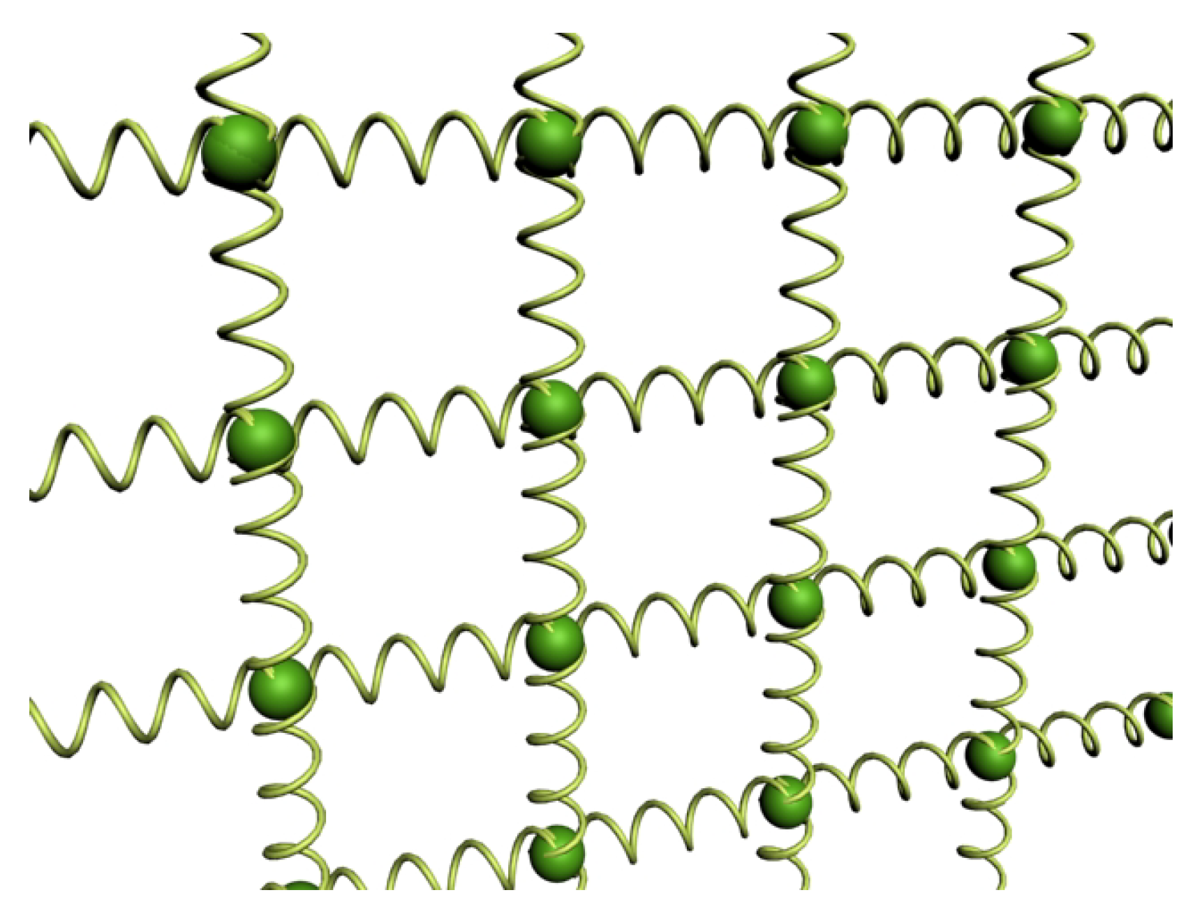
Considering a bidimensional (2D) domain for the nodal points
and choosing the FD approach, the simplest idea is to use several 1D string elements and connect each particle on each string with the corresponding particle of the neighboring string as in
Figure 1.
In this way, it is possible to obtain a simple approximation of soft tissue. The approximation introduced here is given by summing up the errors in the two principal directions leading to perceivable errors in four neighbor modeling approaches.
However, this model is designed for equally distributed rectangular meshes. Hence, it provides poor results if employed for simulating generic triangular meshes. A second drawback is that it is challenging to obtain correct simulation parameters for an actual cloth material because the model parameters have no direct relationship with the physical parameters that are commonly employed in the industry.
For such a reason, when there is the need for accurate physical simulations, a Finite Element dynamical model can be used by employing, for instance, 2D triangular elements organized in an unstructured mesh for the modeling of a garment. In this case, the material parameters are considered by the FEM formulation itself that is obtained from the elasticity theory. The FEM model considers the material as a continuous geometry that is decomposed on discrete elements and solves for a finite set of points associated with them. The solution is finally obtained interpolating on the whole domain. A triangle mesh can be used to represent the surface of the cloth in a discrete domain. FEM elements are the mesh triangles themselves, and FEM nodes are their vertices. Thus, the quality of the simulation strongly depends on the resolution of the triangulation.
3.1. Corotational FEM Modeling
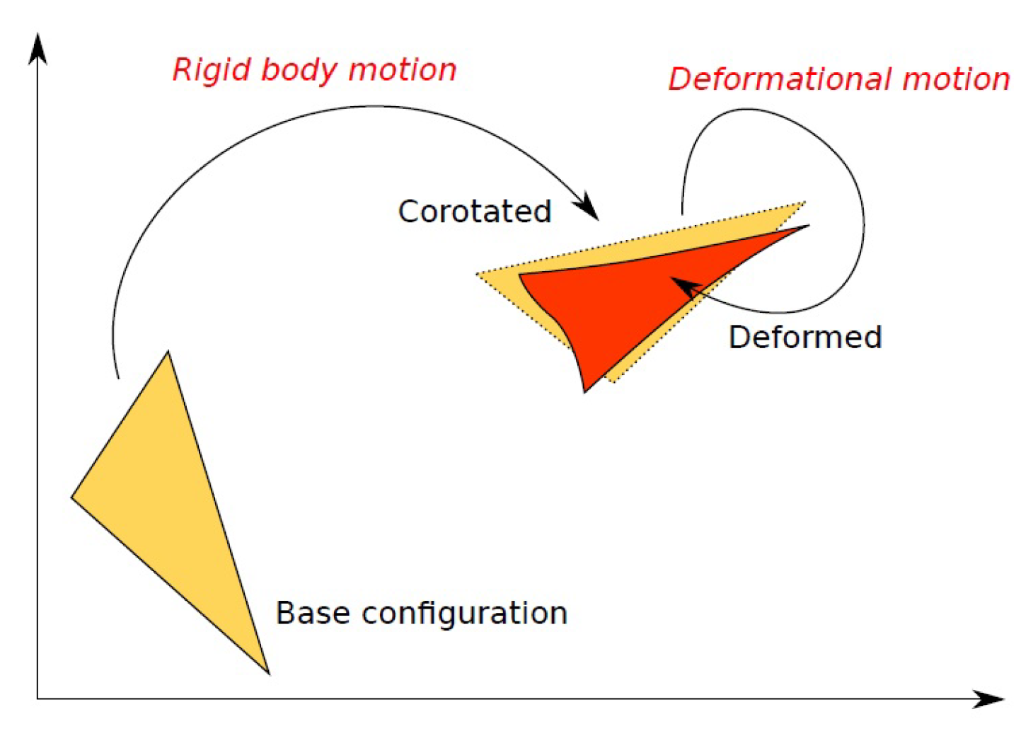
Among the possible Lagrangian kinematic descriptions, the Corotational (CR) [
32] one is based on the assumption that displacements and rotations can be arbitrarily large, but deformations must be small [
33]. The CR description introduces a decomposition of the motion tracking into two components (
Figure 2). Starting from a base configuration that represents the origin of displacements, the final configuration is decomposed into a corotated configuration given by a rigid body motion of the base configuration and a deformed configuration where element deformations are obtained concerning the corotated configuration. Assuming that only small deformations occur between the corotated and deformed configuration, the CR approach allows using a linear formulation to compute the internal forces. Under this assumption, it is possible to represent stiffness by using a symmetric matrix
K.
Calling
and
two adjacent edges of a triangular element in base configuration, it is possible to compute
and
and obtain a base of the 3D space with the matrix
. Computing in the same way a basis
for the deformed configuration, the rotational part is obtained as in [
34]:
The rotation R is used to transform the deformed triangle in the plane of the base configuration, compute the elastic force linearly in that configuration, and then rotate back the obtained forces in the 3D space.
3.2. Fabric Modeling
In work proposed in [
14], the formulation of a linearized stiffness matrix directly characterized by physical elastic parameters taken from Kawabata measurements can be found. In particular, in this implementation, the behavior of the simulated fabric takes into account membrane, bend, and viscosity forces.
Membrane forces are due to stretch, compression, and shear contributions. Using the CR formulation, any deformation occurs in the
z axis, and the analysis can be carried out on a two-dimensional domain. The force acting on the triangle
t can be determined by considering, for each vertex, a contribution produced by the deformation of the connected edges. For a vertex
a and edge
, the force component results as:
where
is the position of the vertex
a in the deformed state,
is its position in the base configuration, and
is composed by the first two columns of the corotational matrix
R. The stiffness matrix is computed as follows:
where
C is the elastic tensor containing the material properties,
is the area of the triangle in the rest state, and
are partial derivatives that can be easily computed for a 2D triangle as:
The global stiffness matrices can be obtained as:
where
is the set of all triangles containing the vertices
a and
b. The final membrane force is computed as:
where
X is the coordinate vector of the deformed vertices and
is the coordinate vector of the base vertices.
In order to consider bending forces, it is necessary to drop the two-dimensional approach and employ finite elements of a higher order. Such contributions can be generated by projecting the Laplacian operator onto the normal surface direction. By calling
, the projection operator relative to the normal
n, it is possible to proceed to calculate the Laplacian operator as:
where
and
are the bending moduli in the weft and warp directions. To estimate the surface curvature, the Laplacian is projected onto all vertex normals
,
, and
of the
a,
b, and
c triangle vertices. A local stiffness matrix can then be calculated as:
From the local stiffness matrices, a global matrix
can be assembled and proceed to solve for the bending forces:
Internal friction and viscosity by contributions are obtained calculating the viscous matrix
in the same way as the elastic matrix, this time inserting the viscosity tensor in replacement of the elastic tensor. The viscosity forces can then be computed as:
Given the above formulation and time discretization with the backward Euler step, a linear system that results in a sparse symmetric linear problem is obtained, and it can be solved with the iterative conjugate gradient algorithm [
35] through preconditioning of the system matrix (PCG).
3.3. Implemented Algorithm
The system proposed in the following section implements the fabric model thanks to the CR formulation introducing a preconditioned sparse symmetric linear problem to be solved by the iterative conjugate gradient algorithm. The fabric mesh is composed of discrete elements, each constituted by nodes (vertices). The number of nodes depends on the representation topology (3 for triangles, 4 for tetrahedra, etc.). The simulation data elements can be static/precomputed or dynamic. In particular, starting from a rest position, the simulation computes
for all the mesh nodes in the subsequent time steps according to the dynamical and mechanical properties of the fabric.
Figure 3 shows the dependency graph in the computation. For each triangle, the area, the surface normal, and its rotation matrix are calculated. The stiffness matrices (
,
, and
) are computed starting from the elastic, bending, and viscous tensors (
). Such elements are employed together to obtain the stiffness contributions at the local level (
). Gathering the contribution of each triangle into sparse matrices
and considering the mass of the fabric associated with each node, the forces accumulated by each element over adjacent nodes and node accumulated forces can be obtained. The external forces
and the nodes velocities
contribute to the set of equations of the linear system. Finally, the PCG algorithm computes the change in the velocity of the nodes that enables the update of the position of the nodes for the next iteration.
4. Interaction with the Fabric
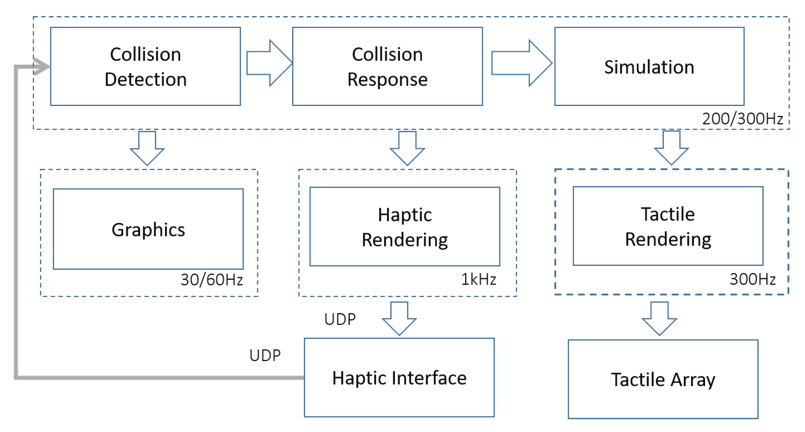
Since the user’s interaction with the fabric happens mainly through the use of the index and thumb fingertips, the haptic device acts exclusively on such fingers. The developed prototype is composed of a kinesthetic haptic device and a tactile display element, each embedded with its own controllers. The fabric simulation is run on a dedicated computer connected with gigabit ethernet to the embedded controller. The functional components of the system are depicted in
Figure 4.
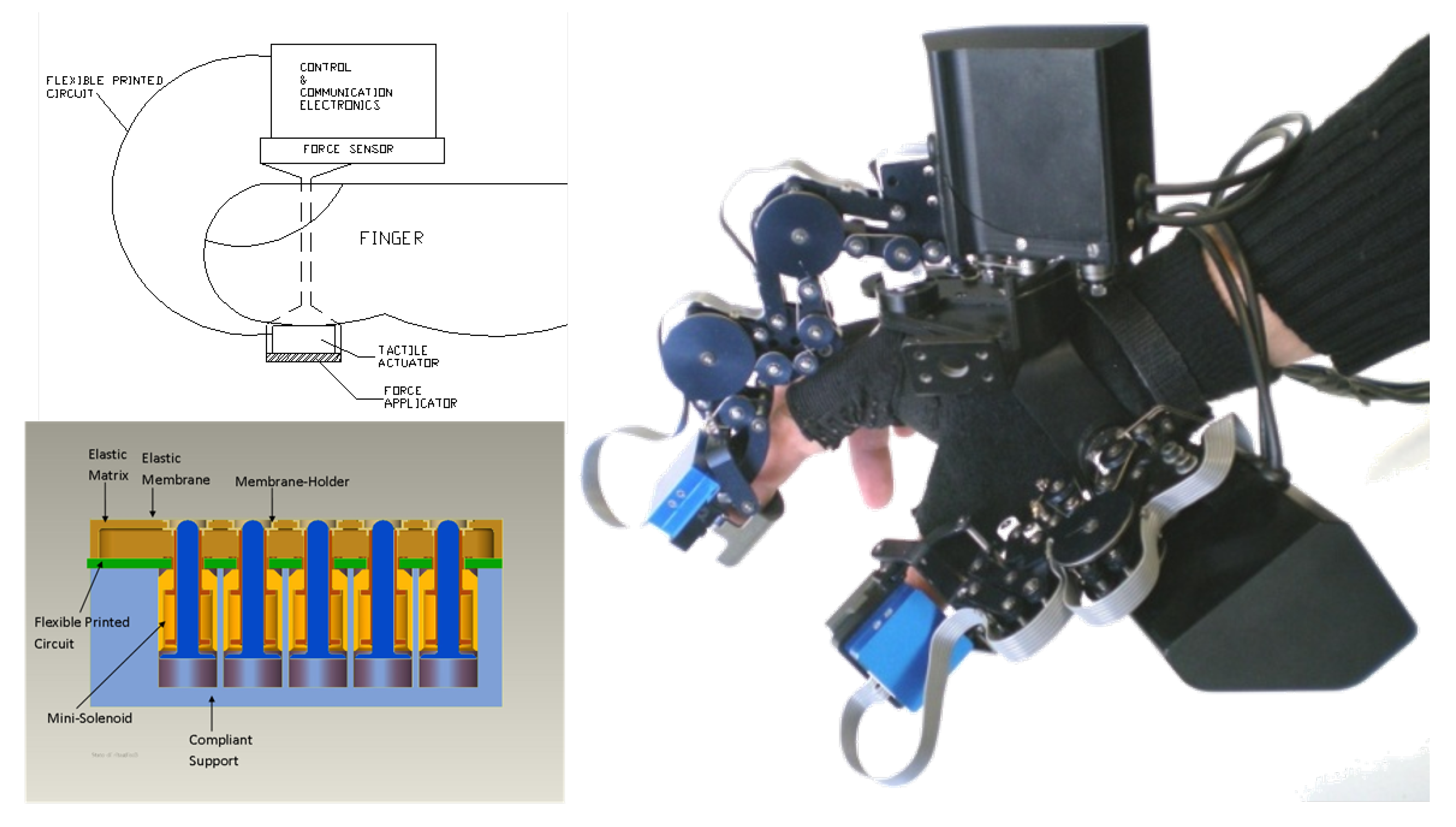
The kinesthetic feedback is produced by the hand exoskeleton introduced by Fontana et al. [
36]. This device allows exerting controlled forces on the index and thumb fingertips of the operator while assuring that the finger motion degrees of freedom are not constrained. Concerning the original assembly, the mechanical plate that comes in contact with the operator’s fingertips (i.e., the end-effector) is substituted with a tactile array device to deliver to the user skin spatial and temporal patterns. The tactile transducer is a 5 × 6 array based on a custom electromechanical minisolenoid designed and optimized for reduced encumbrance and the weight [
37]. The actuator has a diameter of 2.4 mm and is capable of delivering a maximum force of 73 mN.
Figure 5 shows the employed hardware interfaces: the tactile array setup and the hand exoskeleton.
The simulation is run by synchronizing the actual time with the simulation time. Time synchronization is a delicate element that must be satisfied to maintain simulation and interaction stability. The collision detection and response modules determine if a collision occurs between the virtual representation of the operator’s fingertips and the simulated cloth and eventually render a force into the simulation. In the system, undeformable spheres were chosen as the virtual representation for the operator’s fingertips. Hence, the collision detection could be run either per vertex or triangle based. Since the sphere is rigid, the collision response may induce shifting motion on the cloth vertices. The haptic rendering is based on a virtual coupling between the interaction spheres and the index and thumb end-effectors acting as a low-pass filter for the different execution rates. The tactile rendering drives solenoids to produce specific patterns on the operator’s skin. A graphic element is used to visualize the simulation every time a new computation is ready with a stereographic setup (projector and projection screen or 3D monitor). The stereographic setup allows displaying a proper depth sensation to the operator during the manual evaluation. To further reduce the stress on the operator’s hand due to the weight of the haptic device, the latter can be attached from the wrist on a weight-compensating device.
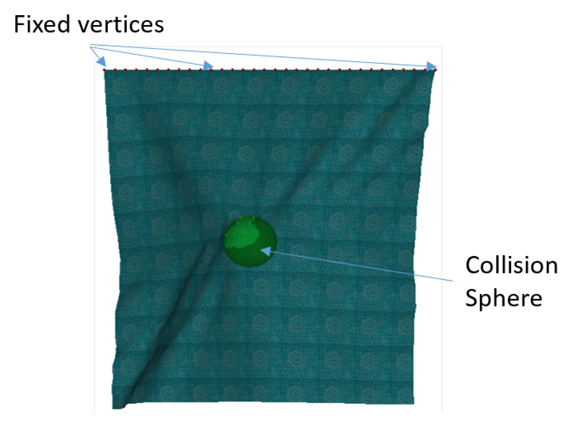
Solving Collisions
The collision check between the cloth and the operator’s fingertips is evaluated by computing the distance between implicit sphere surfaces and textile vertices. An alternative option could be the one of checking the collisions between the spheres and each triangle composing the textile. However, the computational cost of this operation is larger and would require propagating the forces exerted on a specific point of the triangle surface back to the triangle vertices. Given the dimension of the sphere radius (fingertip width) compared to the distance between nodes in the simulated textile (dimension of the triangles), the per vertex collision check is a sufficient approximation that gives a boost to the computational complexity of the algorithm. The cost of this operation is linear to the number of vertices.
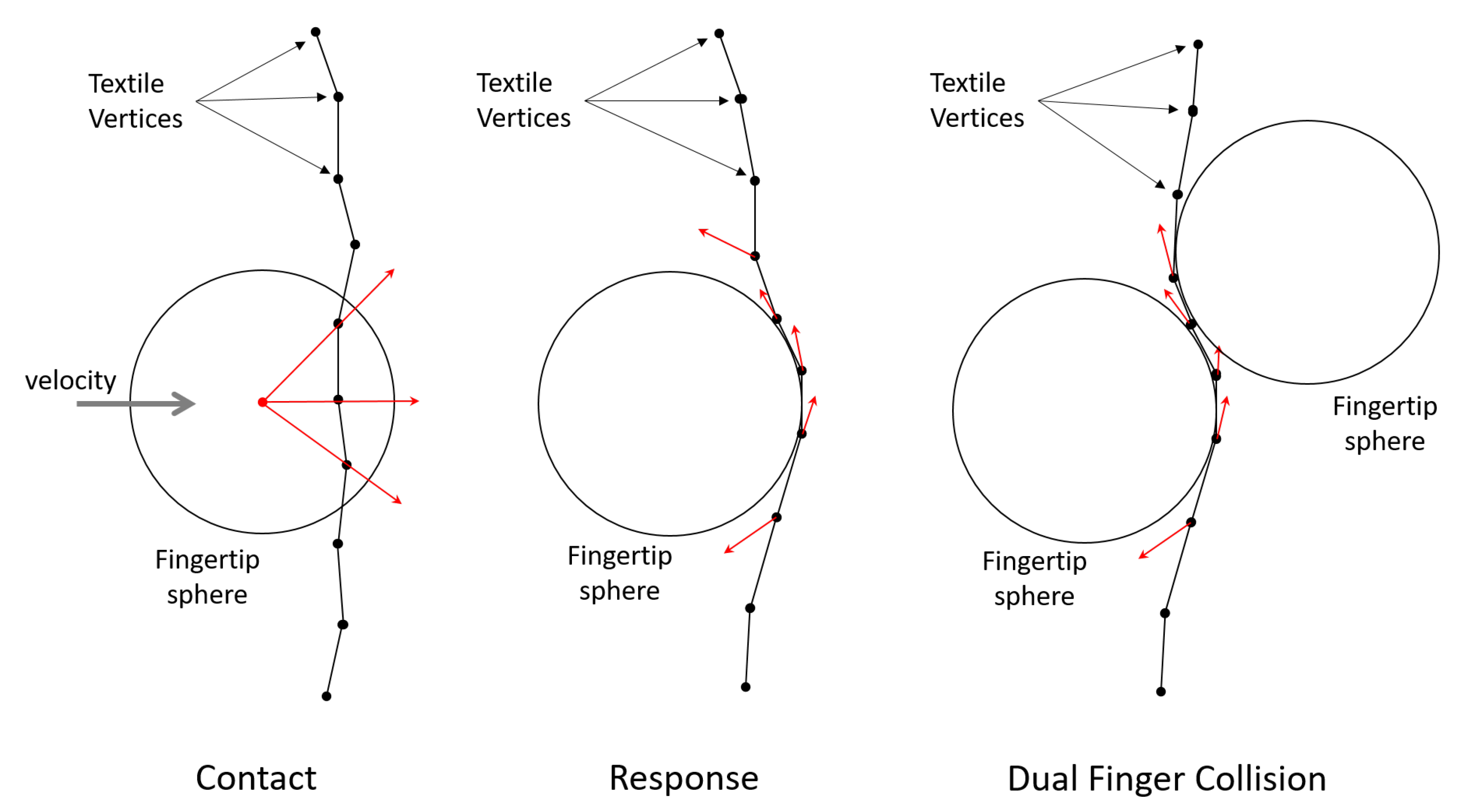
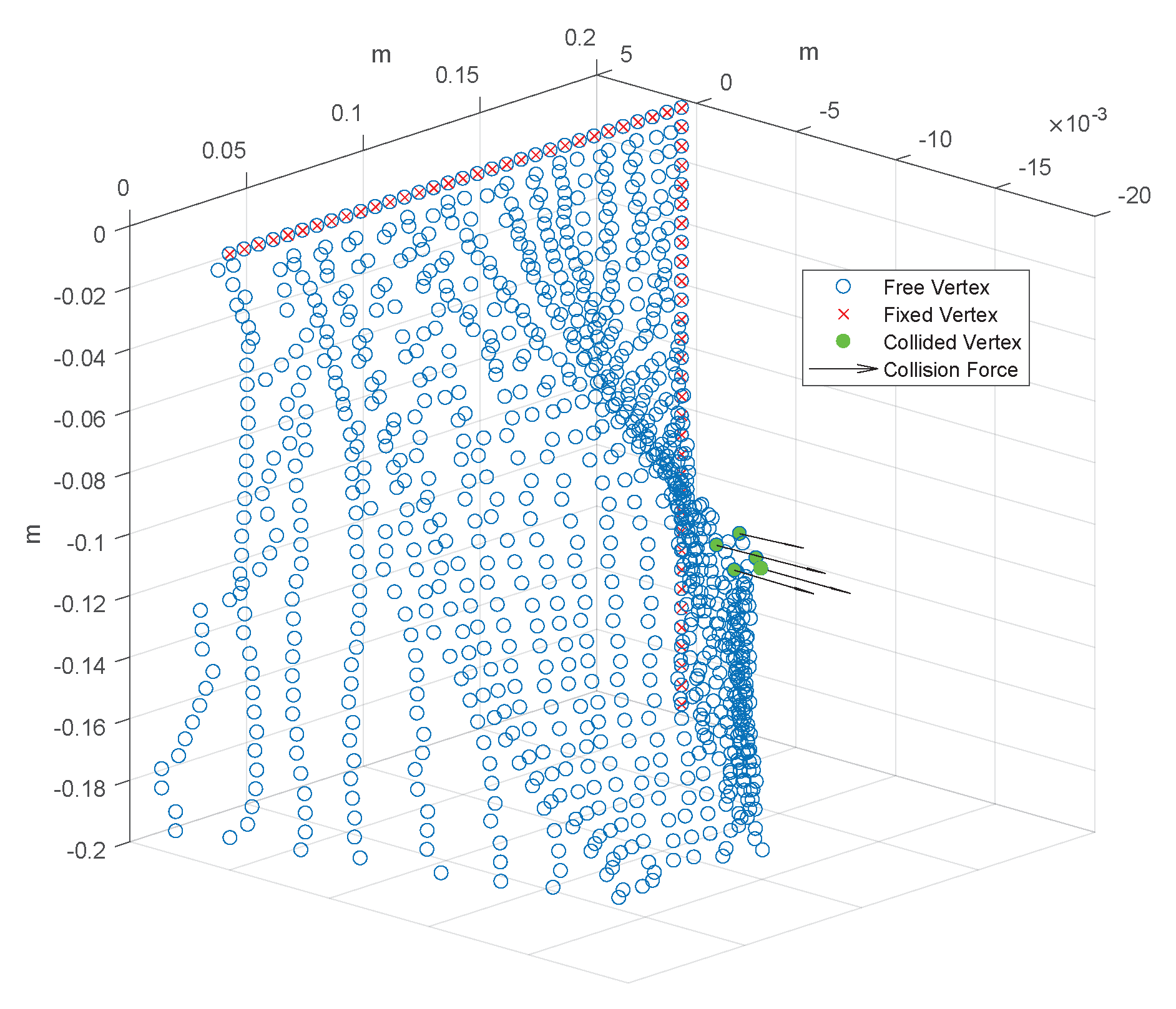
For each vertex colliding with the sphere (see
Figure 6) in the contact phase, a normal vector
directed from the origin of the sphere to the vertex is computed. From the intersection of the normal vector with the sphere surface, a point
P is selected. The corresponding vertex is then moved instantly on the location of point
P before the simulation phase, and it is constrained to move along the tangent space of the normal vector
. The velocity delta of motion along the normal direction is computed following point impact mechanics considering the bounciness factor. By inserting into the equations a friction model between the spheres and the cloth, a sliding relative velocity is computed considering the friction coefficients. In the case of static friction, the vertex is constrained exactly on the contact point
P.
In the case in which both the spheres are colliding with the same vertex, the response must take into account both the constraint directions from which the tangential space must be computed. If the directions of the normals are orthogonal, the tangent space is a line, and the possible direction of motion is unique.
The constrained solution is fundamental to obtain the forces exerted from the cloth to the fingers and then back to the haptic interface. Concerning penalty-based models, the force feedback is computed based on the penetration depth of textile vertices on the sphere. Conversely, in the constrained solution, the force feedback is obtained from the work performed by the constraint reaction. Following the work proposed in [
31], the constraint is inserted in the dynamic equation by projecting the problem on a subspace where such a constraint is always satisfied. This effect can be obtained by filtering the result of the PCG.
Figure 7 shows the effect of constraint reactions on the simulation.


