Abstract
High-speed Permanent Magnet Synchronous Motor (PMSM) systems have been widely used in industry and other fields for their advantages of having a simple structure, low processing cost and high efficiency. At present, the control precision of PMSM is required to be higher and higher, but it faces two major challenges. The first is that the PMSM system possesses (possibly fast) time-varying uncertainty. The second is that there exist nonlinear portions in the PMSM system, such as nonlinear elasticity, etc. To resolve these challenges, a novel performance measure is introduced as a dynamic depiction of the constraint-following error, and a new robust control design is proposed based on . While this control renders guaranteed performance regardless of uncertainty, an optimal design of a control parameter is further pursued. This inquiry is summed up as a semi-infinite constrained optimization problem. After the induction of the necessary condition, the candidate solutions can be identified. These are further screened by a sufficient condition, which results in the actual solution. To verify the effectiveness of the control design, the compressor powered by a super high-speed PMSM system is simulated, and its performance is discussed.
1. Introduction
The modern AC motor actuators in the industrial field face the challenging requirements of high efficiency, high precision, and high performance with advances in digital electronics, industrial machine drives, and control theory. In AC motor actuators, the Permanent Magnet Synchronous Motor (PMSM) system is increasingly popular for its simple structure, low processing cost, high efficiency, and robustness. The PMSM has been widely used in high precision fields, such as robotics, aerospace, large telescopes and so on. However, PMSM is a typical nonlinear and multi-variable coupling system. Moreover, (possibly fast) time-varying uncertainties always affect its control performance and cause ripples in the actual operation [1]. Therefore, designing a high precision PMSM system control is difficult but rewarding.
The motion equation must be obtained first to achieve the control of the PMSM system. Pioneers proposed many forms of constrained motion equations which are based on D’Alembert’s principle [2]. This principle is appropriate for many cases, but not in cases where the constraints are nonholonomic or non-ideal. To overcome the limitation, a simple and explicit decoupled motion equation, the Udwadia–Kalaba equation, is proposed. The theory is known as the Udwadia–Kalaba theory [3,4]. In contrast to the Lagrange method, the Udwadia–Kalaba theory does not need the hard-to-get multiplier. In addition, it provides an efficient way to handle any type of constraints, whether holonomic or nonholonomic constraints, ideal or non-ideal.
The analysis of PMSM system constraints is another central problem. Constraint following problems fall into two types: passive constraint problems and servo constraint problems [5]. The second type is the key issue for precise control design [6,7]. The main focus of servo constraints, which are model-based, is to figure out what the engineer should do, or to figure out the force/torque of the servo mechanism (such as the motor), in order to comply with the constraints. In this paper, the servo robust control is designed based on servo constraints.
At present, the traditional PID control, hysteresis control, and predictive control are commonly used for PMSM [8,9]. PID control has the characteristics of stability, reliability, and simple parameter setting. Nevertheless, it is difficult to meet the high precision application. Because it is easy to cause system overshoot and oscillation when the gain of PID control increases, therefore, scholars adopted many advanced approaches to control the PMSM system, such as sliding mode control [10], interval type-2 fuzzy dynamic high type control [11], predefined-time control [12] and fuzzy-set-based control [13], while the convergance speed is not fast enough when the system state is far from the equilibrium point and the calculation is complicated. Furthermore, the optimal design of the control parameter is not pursued. Robust control is another common tool to deal with uncertainty [14,15,16,17], which has been used in robot manipulators, quadrotors, aerospace and many other mechanical systems. A new Udwadia–Kalaba-based servo robust control approach is presented in this paper to meet the requirement of precise control.
Different from the previous robust control method, in which the control performance is directly measured by constraint error [18,19], a generalized performance measure in the new proposed robust control is introduced as a dynamic depiction of the constraint-following error. The definition of in the previous study is just a special case of . Then, a more practical optimal design of control parameters is also considered [20,21] based on the general control performance.
In summary, this paper has made contributions to four aspects to realize the high precision control of the PMSM. First, a novel system performance measure () is taken as the control object, which is the “dynamic” generalization of the previous “static” measure. Second, a new robust control method for constraint following is proposed, which can guarantee the uniform boundedness and uniform ultimate boundedness of the uncertain compressor/PMSM performance. Third, the relationship between and is explored. Fourth, optimization of the control design parameter is pursued. This task is summed up as a constrained optimization problem of the compressor/PMSM and solved by invoking an necessary condition followed by a sufficient condition.
2. Servo Robust Control
In this section, a new servo robust control is proposed for the precision control of the compressor powered by a super high-speed PMSM system. First, the dynamic model of the uncertain compressor/PMSM system is introduced. Second, the proposed robust control is proved to guarantee the uniform boundedness and uniform ultimate boundedness of the uncertain system.
2.1. Dynamic Model of the Compressor/PMSM System
A compressor powered by a super high-speed PMSM is considered, which is shown in Figure 1. The system can be simplified as a two-mass system, where the first mass represents the super high-speed PMSM, the second mass represents the compressor, and the shaft is considered to be mass free, see Figure 2. Parameters of the system are given in Table 1.
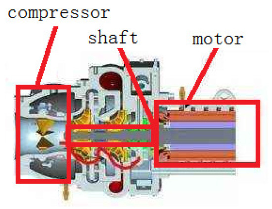
Figure 1.
Compressor powered by a super high-speed PMSM.
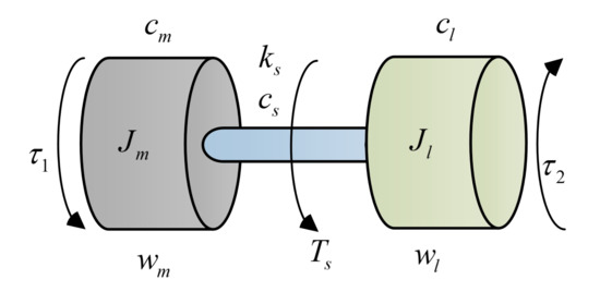
Figure 2.
Two-mass system.

Table 1.
Parameters of two-mass system.
Some parameters of this model are uncertain in the real situation. Based on [22], the uncertain dynamic model of the two-mass system without deadzone is:
Here, is the generalized coordinate vector, is velocity, is acceleration, , where is the time-varying uncertain parameter, is the unknown but compact possible bound of . In addition, is the inertia mass matrix, is the Coriolis force, is gravitational force and other external disturbance forces. is the control torques. Functions M, C, N are all assumed to be continuous and detailed expressions are
Remark 1.
The coordinate x can be chosen according to the specific situation, not necessarily a generalized coordinate. The dimension of is determined by the number of uncertain terms in the two-mass system.
2.2. Problem Formulation
Constraints can be classified as holonomic constraints and nonholonomic constraints. Bsed on [23], both holonomic constraints and nonholonomic constraints can be abbreviated to
where is matrix, . The rank of is not restricted and m is the number of constraints.
Remark 2.
Mechanical systems may be subjected to both nonholonomic constraints and holonomic constraints. These constraint equations do not have to depend on each other.
Assumption 1.
The mass matrix is always greater than 0 for each .
Remark 3.
Assumption 1 is vital. In the past, this was generally accepted as fact. However, the counter situation occurs when the coordinate x is not selected as the generalized coordinate [24].
Definition 1.
For a pair of given A and b, if there is at least one solution , then (5) is consistent.
Assumption 2.
The rank of is greater than 1. Furthermore, all constraints are consistent.
2.3. Servo Robust Control Design
Please note that functions M, C, and N all uncertain. They can be composed as:
where , and are “nominal” portions, and , and are uncertain portions. In addition, above functions are all continuous.
For the mechanical system , under the control , the system needs to follow the desired constraints . In previous study, the control performance is directly measured by the constraint error
and
In this paper, from a new angle, the control performance is defined as
where , and is the performance measure which is the general form to describe the control performance.
Assumption 3.
There is a function and continuous (for ) or (for ), strictly increasing functions , for all
Functions satisfy
That is, there exists a Lyapunov function for an uncontrolled nominal system [24].
Assumption 4.
For all, there is a constantsatisfying
Assumption 5.
There is a known function and an unknown vector α such that
for all and .
Remark 4.
The function is the uncertainty bound.
The servo robust control for the compressor/PMSM system is designed as
where
In (20), κ is a design parameter greater than or equal to 1 (that is ), is defined as
Let
then for given scalar constant
Theorem 1.
Under the conditions of Assumptions 1–5, the proposed control (18) renders the compressor/PMSM system satisfies following properties:
(1) Uniform boundedness: For any with , there is a such that for all ;
(2) Uniform ultimate boundedness: For any with , there is a such that for any as , where .
Proof of Theorem 1.
For a function that satisfies Assumption 3, the first derivative of it is
Then, we analyze the third portion on the right side of (23). We decompose as and decompse as . We can obtain,
According to (19),
Next, according to (17) and
According to , we obtain
By a direct algebra,
Thus, for all
It is concluded that the uniform boundedness with [26]
Furthermore, the uniform ultimate boundedness with [26]
and
□
2.4. Relationship between and
Previously, the control performance is defined as , which is shown in (9). It presents a “static” measure of how constraints are followed. In this paper, the control performance provides a “dynamic” measure of the constraint-following. The novelty of is the introduction of , which allows the flexible design of the control.
The uniform boundedness and uniform ultimate boundedness of the novel system performance measure has been proved. There is a relationship between and .
Let
where , .
According to Theorem 1, for all , ; and for all (), . Then, there exists a supremum such that for all , , that is
Furthermore, there exists a such that for all (), , i.e.,
3. Optimal Parameter Design
3.1. Design of the Performance Index
The proof of Theorem 1 shows that R decreases by increasing the design parameter of the control (). The decrease of R results in the decrease of the ultimate boundedness region size . However, the increase of means an increase in the control cost. Therefore, we should consider the combined effect of changing on R and the control cost.
Let us consider the following performance index
Here is a strictly increasing function , reflecting the control cost due to the use of . The choice of this function can be a part of the design, which should both reflect the control cost and facilitate the feasible solution. The problem is to seek , so that renders a minimum value. This can be expressed as a semi-infinite constrained optimization problem:
3.2. Solution of the Optimization Problem
To solve this optimization problem, we proceed to consider the necessary condition
Due to the properties of , as prescribed in Assumption 3, the derivative of exists. In addition, the derivative of also exists. Taking the derivatives results in
or
Suppose the solution(s) to this equation exist, which are denoted by . The sufficient condition for this optimization problem is then
To sum up, necessary conditions provide candidate solutions for optimizing the problem, while sufficient conditions filter candidate solutions to obtain the (actual) solutions.
Lemma 1.
Suppose and , where , . Then, there always exists an unique solution to the necessary condition (45). The unique solution is
where
and
Remark 5.
For given , p, and q, can be assured by a proper choice of .
This is the unique positive solution to the performance index. With (49), the minimum cost J is given by
3.3. Design Procedure
This is believed to be the most thorough study of an optimization problem, with all three fundamental issues completely solved: existence, uniqueness, and analytic expressions of both and . Since the assumptions are all very fundamental and the procedure only invokes standard numerical computations, the control scheme is quite easily applied. We shall further demonstrate this in the next section. The servo robust control proposed in this paper can be summarized in the following design step flow chart (Figure 3).
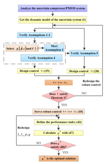
Figure 3.
Design procedure.
Remark 6.
The control scheme is quite easy to implement and compute. For implementations, it only needs position and velocity feedback. Therefore only position and velocity sensors are needed. No acceleration sensors (accelerometers) or vision sensors are needed. For computations, only standard algebraic operations (such as additions, multiplications, etc.) are needed. No complicated operations, such as graphical data conversion or on-line recursive computations, are needed.
4. Simulation and Discussion
4.1. Constraints and Assumptions Verification
Firstly, according to the expression of M in (2), Assumption 1 is verified.
Secondly, suppose that the load mass needs to track the desired trajectory . The error between the coordinates of the load mass and the desired trajectory is defined as
To obtain the desired trajectory quickly, the error can be modified as
Selecting , (54) can be written as
Differentiating (55) once to obtain
Hence, Assumption 2 is verified.
Thirdly, to verify Assumption 3, the function and Lyapunov function should be selected. For the simulation of compressor/PMSM system, we select
where and . Then, the performance measure is represented by
This in turn means in Assumption 3, the function can be selected as
where is a scalar. Then, corresponding functions are, respectively, shown as , ,
Fourth, we consider the inertia moment of motor and load are uncertain and shown as , , where are constant nominal values and are the uncertainties. We also consider the friction of viscous motor, the friction of viscous load, and the inner damping coefficient of the shaft are uncertain and they are, respectively, shown as , , and , where are constant nominal values and are the uncertainty. The elasticity coefficient of the shaft is also considered to be uncertain and shown as , where is the constant nominal value and is the uncertainty. Due to thus Assumption 4 can be verified.
Fifthly, we assume , , , , , ,. Then, Assumption 5 is met by choosing
where
4.2. Parameters Selection
For simulation, the nominal values of parameters are shown in Table 2.

Table 2.
Parameters of two-mass system.
The uncertainties are selected as follows: , , , , , . The initial conditions are selected as , , , . We select , is the weighting. The parameters are selected to be , , , , , , .
4.3. Alternative LQR Design: A Comparison
LQR is a robust control which has been thoroughly studied both in theory and practice. Therefore, it is selected to compare with the proposed servo robust control. Based on LQR control, the linearization of (1) can be transformed into
where
4.4. Simulations and Discussions
The region bounded by the norm of the system performance error () and t is expressed as
where is the simulation time.
Variable time step ODE15i integrator is used for simulation in MATLAB environment. The simulation results are shown in Figure 4, Figure 5, Figure 6, Figure 7 and Figure 8. Figure 4 shows the comparison of system performance between the servo robust control and LQR control. The error between the system performance and the desired trajectory is shown in Figure 5. It is clearly shown that the servo robust control can reach the uniform boundedness more quickly than LQR control. In addition, the uniform ultimate bounded region under the servo robust control is much smaller than that under LQR control. The comparison of S is shown in Figure 6. The S under the servo robust control is more than five times smaller than that under LQR control.
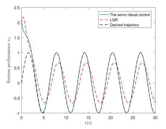
Figure 4.
The system performance.
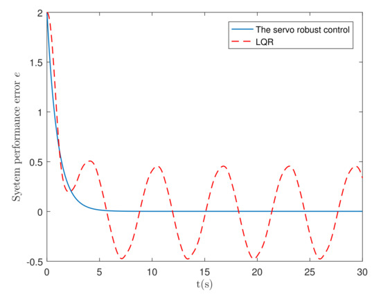
Figure 5.
The system performance error e.
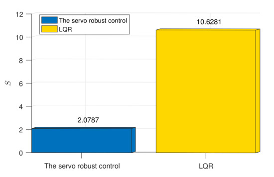
Figure 6.
Comparison of the accumulative constraint error S.
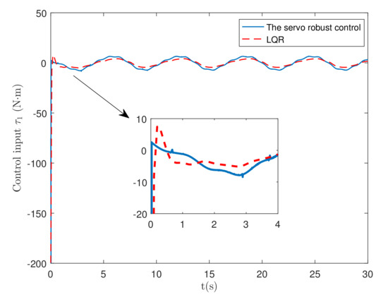
Figure 7.
Control force .
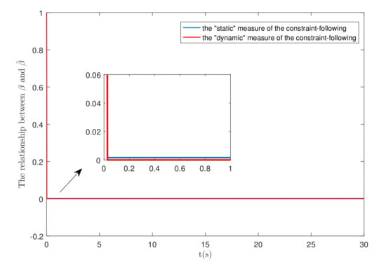
Figure 8.
The relationship between and .
Figure 7 shows the comparison of under two controls (servo robust control and LQR control). At the beginning of the simulation, the LQR control has an overshoot, while the robust control is smooth. There is a surge in the control input of the proposed servo robust control. The reason for the surge in Figure 7 is the initial condition deviation. As shown in (52), the desired trajectory is . The problem can be mitigated by adjusting the parameter .
The comparison of (the “static” measure) and (the “dynamic” measure) under the servo robust control is shown in Figure 8. The “static” measure as well as the “dynamic” measure both can quickly reach a plateau.
5. Conclusions
To achieve high precision control of a nonlinear and uncertain compressor/PMSM system, the desired performance is translated into constraints for processing. Then, a general performance measure with dynamic characteristics is used to solve the constraint following the control problem. The introduction of produces the “dynamic” measure , which enables flexible control design. Regardless of uncertainty, the control renders the measure uniformly bounded and uniformly ultimately bounded. The next inquiry is to seek an optimal choice of the control design parameter . This process is separated into two steps. The first step is to explore the necessary condition, which generates candidate solutions. The second step is to use a sufficient condition to screen these candidate solutions to identify the actual optimal solution. The simulation results show the effectiveness of the new control design.
The paper addresses one performance index and one design parameter for the control design of the two-mass system. Future explorations may involve optimal design for multiple performance objectives and multiple design parameters.
Author Contributions
Investigation, Q.Z. and R.Y.; Methodology, R.Y. and Y.-H.C.; Project administration, Q.Z.; Software, C.L.; Writing—original draft, R.Y.; Writing—review & editing, C.L. and J.G. All authors have read and agreed to the published version of the manuscript.
Funding
This research was funded by National Natural Science Foundation of China of grant number 52005302, and was also funded by Taishan Scholar Program of grant number tsqn201909113, National Natural Science Foundation of China of grant number 52174120 and the Elite Plan of grant number 0104060540418.
Institutional Review Board Statement
Not applicable.
Informed Consent Statement
Not applicable.
Data Availability Statement
Exclude this statement.
Conflicts of Interest
The authors declare no conflict of interest.
References
- Wang, H.; Leng, J. Summary on development of permanent magnet synchronous motor. In Proceedings of the 2018 Chinese Control Furthermore, Decision Conference (CCDC), Shenyang, China, 9–11 June 2018; pp. 689–693. [Google Scholar] [CrossRef]
- Dhaouadi, R.; Hatab, A.A. Dynamic modelling of differential-drive mobile robots using Lagrange and Newton–Euler methodologies: A unified framework. Adv. Robot. Autom. 2013, 2, 1–7. [Google Scholar]
- Udwadia, F.E.; Kalaba, R.E. Analytical Dynamics: A New Approach; Cambridge University Press: New York, NY, USA, 1996. [Google Scholar]
- Udwadia, F.E.; Phohomsiri, P. Explicit equations of motion for constrained mechanical systems with singular mass matrices and applications to multi-body dynamics. Proc. R. Soc. Math. Phys. Eng. Sci. 2006, 462, 2097–2117. [Google Scholar] [CrossRef] [Green Version]
- Papastavridis, J.G. Analytical Mechanics: A Comprehensive Treatise on the Dynamics of Constrained Systems; Oxford University Press: New York, NY, USA, 2002. [Google Scholar]
- Udwadia, F.E. A new approach to stable optimal control of complex nonlinear dynamical systems. J. Appl. Mech. 2014, 81, 1–6. [Google Scholar] [CrossRef] [Green Version]
- Vu, V.P.; Wang, W.J. Polynomial controller synthesis for uncertain large-scale polynomial T-S fuzzy systems. IEEE Trans. Cybern. 2021, 51, 1929–1942. [Google Scholar] [CrossRef] [PubMed]
- Zhen, S.; Peng, X.; Liu, X.; Li, H.; Chen, Y.H. A new PD based robust control method for the robot joint module. Mech. Syst. Signal Process. 2021, 161, 107958. [Google Scholar] [CrossRef]
- Lakhe, R.K.; Chaoui, H.; Alzayed, M.; Liu, S. Universal control of permanent magnet synchronous motors with uncertain dynamics. Actuators 2021, 10, 49. [Google Scholar] [CrossRef]
- Mani, P.; Rajan, R.; Shanmugam, L.; Joo, Y.H. Adaptive fractional fuzzy integral sliding mode control for PMSM model. IEEE Trans. Fuzzy Syst. 2019, 27, 1674–1686. [Google Scholar] [CrossRef]
- Chen, X.; Tong, W.; Mao, Y.; Zhao, T. Interval Type-2 Fuzzy Dynamic High Type Control of Permanent Magnet Synchronous Motor with Vector Decoupling Method. Actuators 2021, 10, 293. [Google Scholar] [CrossRef]
- Cruz, N.; Basin, M. Predefined-time control of full-scale 4D model of permanent-magnet synchronous motor with deterministic disturbances and stochastic noises. Actuators 2021, 10, 306. [Google Scholar] [CrossRef]
- Zheng, Y.; Zhao, H.; Zhen, S.; Sun, H. Fuzzy-set theory based optimal robust constraint-following control for permanent magnet synchronous motor with uncertainties. Control Eng. Pract. 2021, 115, 104911. [Google Scholar] [CrossRef]
- Jin, M.; Kang, S.H.; Chang, P.H.; Lee, J. Robust control of robot manipulators using inclusive and enhanced time delay control. IEEE/ASME Trans. Mechatron. 2017, 22, 2141–2152. [Google Scholar] [CrossRef]
- Shao, X.; Liu, N.; Wang, Z.; Zhang, W.; Yang, W. Neuroadaptive integral robust control of visual quadrotor for tracking a moving object. Mech. Syst. Signal Process. 2020, 136, 106513. [Google Scholar] [CrossRef]
- Guo, H.; Xu, J.; Chen, Y.H. Robust control of fault-tolerant permanent-magnet synchronous motor for aerospace application with guaranteed fault switch process. IEEE Trans. Ind. Electron. 2015, 62, 7309–7321. [Google Scholar] [CrossRef]
- Li, C.; Zhao, H.; Sun, H.; Chen, Y.H. Robust bounded control for nonlinear uncertain systems with inequality constraints. Mech. Syst. Signal Process. 2020, 140, 106665. [Google Scholar] [CrossRef]
- Chen, Y.H.; Zhang, X. Adaptive robust approximate constraint-following control for mechanical systems. J. Frankl. Inst. 2010, 347, 69–86. [Google Scholar] [CrossRef]
- Zhao, R.; Li, M.; Niu, Q.; Chen, Y.H. Udwadia–Kalaba constraint-based tracking control for artificial swarm mechanical systems: Dynamic approach. Nonlinear Dyn. 2020, 100, 2381–2399. [Google Scholar] [CrossRef]
- Yu, R.; Chen, Y.H.; Han, B. Cooperative game approach to robust control design for fuzzy dynamical systems. IEEE Trans. Cybern. 2020. [Google Scholar] [CrossRef]
- Sun, Q.; Yang, G.; Wang, X.; Chen, Y.H. Designing robust control for mechanical systems: Constraint following and multivariable optimization. IEEE Trans. Ind. Inform. 2019, 16, 5267–5275. [Google Scholar] [CrossRef]
- Nordin, M.; Gutman, P.O. Controlling mechanical systems with backlash-A survey. Automatica 2002, 38, 1633–1649. [Google Scholar] [CrossRef]
- Chen, Y.H. Second-order constraints for equations of motion of constrained systems. IEEE/ASME Trans. Mechatron. 1998, 3, 240–248. [Google Scholar] [CrossRef]
- Khalil, H.K. Nonlinear Systems, 3rd ed.; Prentice-Hall: Upper Saddle River, NJ, USA, 1996. [Google Scholar]
- Noble, B.; Daniel, J.W. Applied Linear Algebra, 2nd ed.; Prentice-Hall: Upper Saddle River, NJ, USA, 1977. [Google Scholar]
- Corless, M.J.; Leitmann, G. Continuous state feedback guaranteeing uniform ultimate boundedness for uncertain dynamic systems. IEEE Trans. Autom. Control 1981, 26, 1139–1144. [Google Scholar] [CrossRef] [Green Version]
Publisher’s Note: MDPI stays neutral with regard to jurisdictional claims in published maps and institutional affiliations. |
© 2022 by the authors. Licensee MDPI, Basel, Switzerland. This article is an open access article distributed under the terms and conditions of the Creative Commons Attribution (CC BY) license (https://creativecommons.org/licenses/by/4.0/).