Abstract
The ionic polymer metal composite (IPMC) actuator is a kind of soft actuator that can work for underwater applications. However, IPMC actuator control suffers from high nonlinearity due to the existence of inherent creep and hysteresis phenomena. Furthermore, for underwater applications, they are highly exposed to parametric uncertainties and external disturbances due to the inherent characteristics and working environment. Those factors significantly affect the positioning accuracy and reliability of IPMC actuators. Hence, feedback control techniques are vital in the control of IPMC actuators for suppressing the system uncertainty and external disturbance. In this paper, for the first time an adaptive full-order recursive terminal sliding-mode (AFORTSM) controller is proposed for the IPMC actuator to enhance the positioning accuracy and robustness against parametric uncertainties and external disturbances. The proposed controller incorporates an adaptive algorithm with terminal sliding mode method to release the need for any prerequisite bound of the disturbance. In addition, stability analysis proves that it can guarantee the tracking error to converge to zero in finite time in the presence of uncertainty and disturbance. Experiments are carried out on the IPMC actuator to verify the practical effectiveness of the AFORTSM controller in comparison with a conventional nonsingular terminal sliding mode (NTSM) controller in terms of smaller tracking error and faster disturbance rejection.
1. Introduction
Soft actuators are made of materials, which can deform in response to external forces and thermal stresses. Such materials can be in the form of particles, polymers, fluids, shape memory alloys (SMAs), liquid metals, hydrogels, or a combination of these [1]. Their favourable characteristics, such as low actuating voltage (<5 V), high power efficiency and biocompatibility make them suitable for soft mechatronics and robotic applications [2,3]. Among these, ionic polymer metal composite (IPMC) has attracted attention in many areas. The IPMC consists of a thin ion exchange membrane and two electrodes [4]. By applying a low electric field across these electrodes, a bending displacement can be created [5]. Conversely, an electrical signal will be produced when IPMC is mechanically deformed. In comparison with other smart materials, various desirable features, such as low driving voltage, agility, light weight, noiselessness give IPMC superiority [6]. These properties make this material suitable for diverse applications, including bio-devices, micro-pumps and sensors for measuring velocity, viscosity and blood pressure [7,8,9,10,11,12]. However, the main challenge for the use of an IPMC actuator is to achieve accurate tracking, as the inherent nonlinearity of this material, caused by hysteresis and creep, makes its control a non-trivial task. Furthermore, other challenges also include parameter uncertainties and external disturbances imposed from the working environment along with the physio-chemical complexity of IPMC material and the lack of a universal and precise model for the IPMC system, which thus have been further investigated in the literature [13,14,15].
Various studies have revealed the characteristics of IPMC material and proposed different control algorithms including classic strategies such as impedance control [16]. Bhat et al. [17] designed a lead-slack controller to control an IPMC actuator dependent on a cross hybrid control system. The outcomes demonstrated the adequacy of the technique in an accurate regulation. Bandopadhya et al. [18] designed a PD controller to control a manipulator using an IPMC actuator. However, some studies showed that these classic strategies are not effective for such a material with highly nonlinear properties. Therefore, different adaptive control systems have been designed based on the existing models of hysteresis and creep to capture their dynamics and compensate for their changes [15,19,20]. One drawback of these control systems are that they are only suitable for short time actuation and in the absence of water. Hence, there is a need for designing a control system for underwater soft actuator with relatively long time actuation. Paddison et al. [21] worked on a procedure to quantify the wide range frequency of the overall permittivity of Nafion in water. Their outcomes demonstrate that the dielectric constant increments with adding water substance and diminishes with expanding frequency. Also, if a DC voltage is applied for adequate time, the initial deflection will change to steady state, which would rely on the backbone. This phenomenon is believed due to the overabundance concentration of water closing the cathode and its subsequent back-flux [22].
The sliding mode control (SMC) method, which is a powerful tool for control design of uncertain linear and nonlinear systems, have been applied for precise tracking control [23]. For example, the SMC method has been used not only for IPMC control but also linear springs [24], electrohydraulic systems [25] and industrial manipulators [26]. Liaw et al. proposed an improved SMC method which was used for the piezoelectric actuators to follow indicated movement trajectories [27]. Although both piezoelectric and IPMC actuators are smart materials, they have many different characteristics [28]. Wang et al proposed an adaptive SMC controller to improve the position tracking capability of polymer actuators [29]. This research concentrated on controlling the tip of the IPMC actuators for a scope of trajectories. However, the main disadvantage of the SMC is the induced high-frequency and strong chattering behaviour along the control loop that may bring damages to the physical systems. To overcome the chattering issue, high-order sliding mode [30], super twisting algorithm [31], low-pass filtering [32], and the boundary layer techniques [33] have been proposed. However, in most of these strategies, the prior information about the upper bound of perturbation terms is required, which is often not applicable in the real world. In addition, either the control precision or the system transient performance would be degraded as a compromise. Another problem of the conventional SMC is its relatively long asymptotic convergence property. This problem can be avoided by using the recursive control structure, in which the reaching phase is eliminated while the finite-time convergence is guaranteed [34]. For instance, Tong et al. [35] proposed a recursive reaching-phase eliminated terminal sliding mode (TSM) control scheme for multi-input multi-output systems and others [36,37,38,39] have also extended the applications of TSM to a variety of systems including ground and flight vehicles. However, the main drawback of the TSM approaches is the singularity problem of the controller that limits its implementation. To address this issue, Khawwaf et al. [6] employed a nonsingular terminal sliding mode (NTSM) controller for the tracking control of IPMC actuators. Nevertheless, in most of the aforementioned methods, the signum function explicitly exists in the discontinuous control law that may degrade the control signal smoothness.
This paper aims to develop a fast-response, high-precision, and chattering-free sliding mode control scheme to enhance the robust tracking control performance of IPMC soft actuators working underwater. To achieve this goal, an adaptive full-order recursive terminal sliding-mode (AFORTSM) controller is proposed. In this method, a new integral nonlinear hyperplane-based sliding manifold is designed by combining the NTSM with an integral terminal sliding mode (ITSM), which can lead to reduced convergence time and smaller tracking error with retained robustness. The performance of the proposed AFORTSM is then compared with the NTSM control method, which indicates that this new method eliminates the reaching phase with the help of the internal integral sliding mode and then achieves the successive finite-time convergence of the system along the dual-layer sliding surfaces. Moreover, the inherent full-order sliding mode makes the reaching control input be the integral of the signum function which is useful for suppressing control signal chattering. In addition, an adaptive control gain is proposed for the reaching law such that the need for prior knowledge of the upper bound of the uncertainty and disturbance is eliminated. In the rest of the paper, a dynamic model of the IPMC actuator with parametric uncertainty is first presented. Then, the control design procedure is elaborated. Moreover, theoretical proof is given to show that the proposed AFORTSM can guarantee the system tracking error to converge to zero in a finite time. The proposed AFORTSM control improves the tracking performance of the conventional NTSM controller in [6], which are finally verified through the experiments on a real IPMC actuator.
2. Plant Modelling
The experimental setup for the IPMC soft actuator working underwater is shown in Figure 1. An IPMC strip with a 3-dimensional size of 40 mm × 10 mm × 0.2 mm is submerged in a water tank. The IPMC is formed by a thin Nafion-117 membrane that is covered by two surfaces made up from platinum thin film electrodes. The deflection of the actuator tip is measured by a high-precision laser position sensor (ILD1420-10, MICRO-EPSILON) with a resolution of 0.5 μm and a range of 10 mm. In addition, a dSPACE-DS1103 rapid control prototyping system is used to implement the real-time controller for the IPMC actuator through the interface with MATLAB/Simulink on a PC. In our study, the sampling rate of the real-time controller is set as 250 Hz.
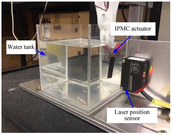
Figure 1.
Experimental setup of an IPMC soft actuator for position tracking control underwater.
For the design of the proposed controller, a dynamic model of the IPMC actuator is required. As aforementioned, the IPMC actuator is of high nonlinearities such as creep and hysteresis that are hard to identify by a mathematical model. As such, we will consider those nonlinearities as uncertainties in this study and thus focus on a simple model for the IPMC actuator. Through an experimental identification procedure by injecting a step input voltage to the IPMC actuator and collecting the output displacement [6], we have found that the IPMC actuator can be modeled by a second-order differential equation as follows:
where y is the IPMC displacement. is referred to as the nominal term related to its displacement and speed and denotes its uncertain component, respectively. represents the unknown lumped uncertainty including the unmodeled nonlinear dynamics, parameter variations, external disturbance, etc. u and are the control voltage and its derivative, respectively. , , , and are the identified constants with = 0.0031, = 0.0146, = 0.4357, and = 0.1219, respectively. For more details on this model, the reader is referred to [6].
The control objective is to design a robust controller to achieve the fast and accurate position control of the IPMC actuator in the presence of system uncertainties. To facilitate the subsequent control design, we shall define the following variables:
where e is the position tracking error with the reference command. v is the new control input to be designed, and the actual control input u can then be obtained by the filter (3). represents the reformatted uncertainty. From the definition in (4), it can be seen that the derivative of is associated with the displacement, velocity and acceleration of the IPMC motion. Thus, the derivative of can be assumed to be bounded by
where , , and are all unknown positive constants. Based on the preceding variables, the error dynamic equation of (1) can be obtained as
which will be adopted for the control design from now on.
3. Control Design
In this section, an AFORTSM controller is proposed for the IPMC to track the reference command with high precision and fast speed under modelling errors, parametric uncertainties and external disturbances. To achieve this goal, a recursive integral terminal sliding mode is constructed. Based on the inherent integral sliding mode, the reaching phase is removed. Meanwhile, finite-time convergence is ensured because of the terminal sliding mode property. In addition, to handle system uncertainties, an adaptive gain is employed to approach their upper bounds in real time. Finally, selection guideline of the control parameters is discussed.
3.1. Construction of the AFORTSM Controller
To construct the AFORTSM controller, we first introduce the following fast non-singular terminal sliding function [40] given by
where , are positive constants such that the polynomial, which corresponds to the system (7), is Hurwitz. and are the positive control parameters satisfying
and the notation is a simplified expression of
In [41], it has been proved that when in (7), the tracking error e converges to zero in a finite time . Next, we propose a recursive integral terminal sliding function s as follows:
where is as defined in (7), and is of the form
with the control parameters , . In addition, to reduce the reaching time, the initial value of the integral element is set as
Substituting (12) into (10), it is straightforward to verify that the sliding variable . This implies that the control system is enforced to start on the sliding surface at the initial time such that the reaching time is removed [34]. Since the initial states of the IPMC are available in practice, can be calculated by
Finally, we shall give the form of the AFORTSM controller based on the recursive integral terminal sliding function. By letting , , we can obtain the following equivalent control input:
Further, a reaching control input [42] is introduced
where the control parameter is updated by the following adaptive law:
with to be designed and . Hence, the overall control input of the AFORTSM can be constructed as
3.2. Stability Analysis
The result for the proposed AFORTSM controller is summarized in the following theorem and stability analysis is provided.
Lemma 1.
Proof of Lemma 1 is provided in Appendix A.
Theorem 1.
Proof.
Next, choose the following Lyapunov function candidate
where , . Solving the derivative of (23) along the system trajectories and substituting (22) and (21) to it yields
From Lemma 1, we have obtained . Then, (24) becomes
Define the following symbols
where . It is obvious that from (5), and for any , there exists a positive constant such that that implies . Then, (24) can be rewritten as
where
Since there must exist a constant lower bound for any such that is satisfied, the following inequality holds
It can be seen that the inequality (28) satisfies the finite time stability criterion in Appendix B. Specifically, V will converge from any initial condition to zero in the finite time given by
which indicates that the sliding variable s and the estimation error will both converge to zero in the finite time of (29). In addition, as in the aforementioned discussion, when , and e will successively converge to zero in the finite time of and , respectively. Therefore, the tracking error e will converge from any initial condition to zero in the finite time of .
The proof is thus completed. □
Remark 1.
The proposed recursive terminal sliding mode (RTSM) consists of two layers of sliding functions as shown in (7) and (10). Based on the RTSM, the system moves along the sliding surfaces and then and finally converges to the origin in finite time. In this sequence, each sliding surface is reached successively [43]. As given in (13), can be guaranteed by selecting a certain initial value of the integral element such that the reaching phase is eliminated. Moreover, different from the conventional ISMC [44] and the adaptive SMC [13], finite-time convergence is guaranteed based on the proposed RTSM. Moreover, the value of is also decreased since . As a result, the time for V to reach the origin is reduced as can be seen from (29).
Remark 2.
Thanks to the use of a second-order sliding function in (7), full-order sliding mode can be achieved. It can be seen that the proposed reaching control input (16) is of an integral form, which means that the chattering effect caused by the signum function is soften. The full-order sliding mode property is useful to achieve both smooth and high-precision control performance for IPMC actuator without impacting its transient response. Those beneficial properties have greatly enhanced the existing methods that use NTSM or filter-based control [13,34].
Remark 3.
In practical applications, the sliding variable s is impossible to stay at zero persistently because of the measurement noise. Instead, as indicated by (17)–(20), s will be chattering around zero, which may result in a conservatively large estimated value of . To alleviate this disadvantage, a dead zone technique [45] is recommended and thus the adaptive law can be modified as follows:
where , is a small dead zone size to be selected. From (30), it can be seen that when s is within the dead zone, will retain its present value. One can verify that when , the inequality (26) still holds, i.e., the finite-time stability is still guaranteed.
3.3. Control Parameter Selections
In practical applications, the impacts from different factors on tracking accuracy, control signal smoothness, and robustness have to be compromised [42]. In the following, the guideline of selecting the control parameters for the proposed AFORTSM controller will be discussed and their values for the IPMC actuator control system will be given.
- (1)
- (2)
- Selections of λ, β: As given in (14) and (15), a larger or a smaller in (10) implies a smaller bound of convergence time for but at the cost of increased control input amplitude. In addition, a larger value of will increase the amplitude of the integral element, which implies a smaller steady-state tracking error [34]. Here, we select , .
- (3)
- Selections of (): To achieve a fast estimation of the control gain, the values of can be selected to be sufficiently small as indicated in (17)–(20). However, too small may cause severer overestimation or even lead to the IPMC actuator saturation. Through some tuning in the experiments, , are fixed for the tests.
4. Experimental Results
Experiments are carried out on the developed IPMC actuator setup as shown in Figure 1 to demonstrate the efficiency of the proposed AFORTSM controller. The reference commands under test include a single-tone sinusoidal waveform and a dual-tone sinusoidal waveform, which can be expressed as follows:
where A denotes the amplitude and f the frequency in Hertz. Moreover, the working condition of the IPMC actuator is configured as
- Without uncertainty: IPMC actuator is fully submerged in the water;
- With uncertainty: IPMC actuator is partially (three-quarters) submerged in the water;
- With disturbance: A shock electrical signal is added onto the control input.
The configurations of all the tests, which are a combination of various reference commands with uncertainty and disturbance, are listed in Table 1.

Table 1.
Configurations of the experimental tests.
To quantify the tracking control performance of the IPMC actuator, the maximum absolute tracking error (MAXe) as well as its root mean square (RMSe) are used, which is defined by the following equations:
where n denotes the number of samples; and j is the sample index. In addition, we compare the performance under the proposed AFORTSM controller and the NTSM controller as previously reported in [6].
4.1. Single-Tone Sinusoidal Tracking
Figure 2, Figure 3 and Figure 4 show the experimental results of tests 1 to 3, which are tracking single-tone sinusoidal references of different amplitudes and frequencies. In comparison with the NTSM controller, the AFORTSM controller has reduced the MAXe by more than for the same single-tone sinusoidal reference and significantly improved RMSe by more than 31%. In addition, the high-frequency chattering in the tracking error profiles under AFORTSM controller is smaller than that under NTSM controller, which indicates that the AFORTSM controller has less impact on vibrating the IPMC mechanism. However, it should be pointed that as the cost of the improved tracking accuracy, the control input amplitude under the AFORTSM controller is reasonably a bit larger than that under the NTSM controller.
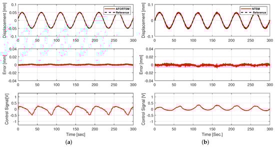
Figure 2.
Test 1: Experimental results of AFORTSM and NTSM for tracking a single-tone sinusoidal reference without uncertainties (top: tracking profiles; middle: tracking error; bottom: control signal). (a) AFORTSM; (b) NTSM.
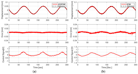
Figure 3.
Test 2: Experimental results of AFORTSM and NTSM for tracking a single-tone sinusoidal reference without uncertainties (top: tracking profiles; middle: tracking error; bottom: control signal). (a) AFORTSM; (b) NTSM.
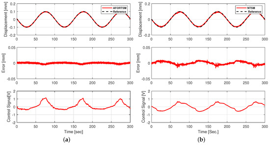
Figure 4.
Test 3: Experimental results of AFORTSM and NTSM for tracking a single-tone sinusoidal reference without uncertainties (top: tracking profiles; middle: tracking error; bottom: control signal). (a) AFORTSM; (b) NTSM.
4.2. Dual-Tone Sinusoidal Tracking
To evaluate the tracking performance for a more complex reference, test 4 is performed with a dual-tone sinusoidal reference command, whose frequencies are comprised of and Hz. Figure 5 presents the tracking performance of the AFORTSM and NTSM controllers for this test case. It can be seen that the MAXe was further reduced by under the AFORTSM controller, which also reduces the RMSe by 31%. This improvement ratio is even higher than those of the single-tone sinusoidal tracking cases. Hence, this test demonstrates that the proposed AFORTSM controller can obtain smaller tracking error over a certain range of frequency bandwidth when compared with the NTSM controller.
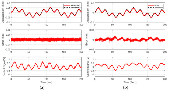
Figure 5.
Test 4: Experimental results of AFORTSM and NTSM for tracking a dual-tone sinusoidal reference without uncertainties (top: tracking profiles; middle: tracking error; bottom: control signal). (a) AFORTSM; (b) NTSM.
4.3. Robustness Verification
As aforementioned, the uncertainty in our application is regarded as the working condition of the IPMC actuator to be either fully or partially submerged in the water, under which the control system is anticipated to retain robust tracking performance. Thus, we carry out tests 5–7 with the same references as tests 1–3 except that the IPMC actuator is with uncertainty (i.e., only three-quarters submerged in the water). Similarly, Figure 6, Figure 7 and Figure 8 show that the performance under the AFORTSM controller is still superior to that under the NTSM controller. On average, the reduction ratio of the MAXe has been improved by approximately and also the RMSe has been improved by . It is noted that the inclusion of uncertainty to the IPMC actuator has deteriorated its tracking error by about on average when compared with those without uncertainty. However, this degradation is inevitable since leaving out of water will have a significant impact on the IPMC characteristics.
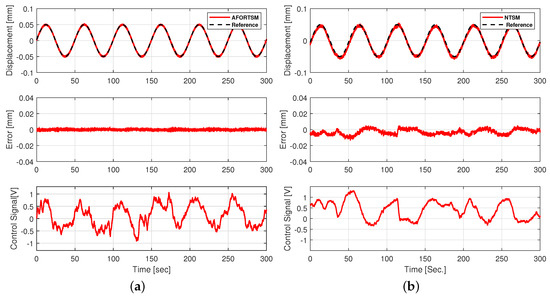
Figure 6.
Test 5: Experimental results of AFORTSM and NTSM for tracking a single-tone sinusoidal reference with uncertainties (top: tracking profiles; middle: tracking error; bottom: control signal). (a) AFORTSM; (b) NTSM.
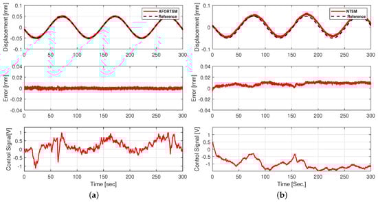
Figure 7.
Test 6: Experimental results of AFORTSM and NTSM for tracking a single-tone sinusoidal reference with uncertainties (top: tracking profiles; middle: tracking error; bottom: control signal). (a) AFORTSM; (b) NTSM.
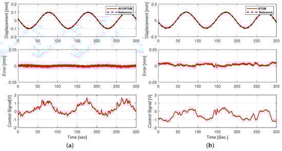
Figure 8.
Test 7: Experimental results of AFORTSM and NTSM for tracking a single-tone sinusoidal reference with uncertainties (top: tracking profiles; middle: tracking error; bottom: control signal). (a) AFORTSM; (b) NTSM.
4.4. Disturbance Rejection
The IPMC actuator may be subjected to external disturbance during operation. Hence, test 8 is conducted to evaluate its performance robustness against an electrical shock disturbance, which is artificially added to the control input. The shock disturbance has a duration of s and an amplitude of 3 V. According to Figure 9, the AFORTSM controller has a smaller overshoot than the NTSM controller and particularly the settling time under the AFORTSM controller has been reduced by s. This verifies the superiority of fast convergence characteristics of the proposed AFORSTM controller over the conventional NTSM controller.
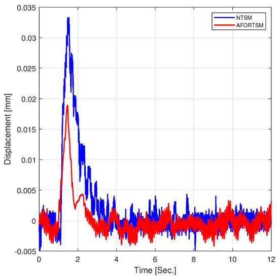
Figure 9.
Test 8: Experimental results of shock disturbance rejection.
4.5. Summary and Comparison
Table 2 summarises the performance for all test cases under the two controllers studied in this paper. According to this table, the proposed AFORTSM controller achieves superior performance compared with the NTSM controller in each case, whose improvement ratio ranges from 19% to 63% among the test cases for MAXe and from 31% to 83% for RMSe. Also, the comparison of the tests 5–7 (with uncertainty) to tests 1–3 (without uncertainty) shows that the proposed AFORTSM controller is significantly less sensitive to uncertainty compared with the NTSM controller. This has verified the proposed AFORTSM controller can enhance the performance robustness.
Table 2.
Summary and comparison of experimental results.
5. Conclusions
The robust AFORTSM controller is proposed for the position tracking control of an IPMC soft actuator working underwater. The proposed controller has the benefits of finite-time convergence, reduced tracking error, and being chattering-free, which are owed to the proposed full-order recursive terminal sliding mode and the integral element in the reaching control law. In addition, to remove the requirement for the upper bound of disturbance derivative during the control design, an adaptive algorithm is developed to update the control gain automatically in accordance with the varying disturbance. The proposed AFORTSM controller is verified on a real IPMC actuator and the experimental results for sinusoidal reference tracking show that it can further reduce the maximum and root mean square of the tracking errors by over and , respectively, in comparison with the conventional NTSM controller. Furthermore, it can achieve faster disturbance rejection, which also coincides with the theoretical property of the AFORTSM.
Author Contributions
Methodology, K.S., R.Z.E., J.K., H.W., J.Z.; validation, R.Z.E. and J.K.; writing original draft preparation, R.Z.E., K.S., J.Z., H.W.; resources and supervision, J.Z., X.C., and M.N. All authors have read and agreed to the published version of the manuscript.
Funding
This research received no external funding.
Data Availability Statement
The data that support the findings of this study are available from the corresponding author, J.Z., upon reasonable request.
Conflicts of Interest
The authors declare no conflict of interest.
Appendix A
According to (22), from onwards the adaptive gain will be sufficiently large to enforce the sliding variable s to decrease. Meanwhile, the adaptive gain will continue to increase until is reached in a finite time . From then on, will retain its final value of . Because of the continuity property, the value of is finite, i.e., is upper bounded. Therefore, there must exist a positive number such that in (5) is satisfied.
This completes the proof of Lemma 1.
Appendix B
Given the following first-order nonlinear differential inequality
where the constants , . is a positive Lyapunov function with respect to the state . Then, the function will converge from any initial condition to the origin in a finite time given by
The derivation is referred to [46] and references therein.
References
- El-Atab, N.; Mishra, R.B.; Al-Modaf, F.; Joharji, L.; Alsharif, A.A.; Alamoudi, H.; Diaz, M.; Qaiser, N.; Hussain, M.M. Soft Actuators for Soft Robotic Applications: A Review. Adv. Intell. Syst. 2020, 2, 2000128. [Google Scholar] [CrossRef]
- Kim, J.; Kim, J.W.; Kim, H.C.; Zhai, L.; Ko, H.U.; Muthoka, R.M. Review of soft actuator materials. Int. J. Precis. Eng. Manuf. 2019, 20, 2221–2241. [Google Scholar] [CrossRef]
- Wang, J.; McDaid, A.; Sharma, R.; Aw, K.C. A compact ionic polymer metal composite (IPMC) system with inductive sensor for closed loop feedback. Actuators 2015, 4, 114–126. [Google Scholar] [CrossRef]
- Truong, D.Q.; Ahn, K.K.; Nam, D.N.C.; Yoon, J.I. Identification of a nonlinear black-box model for a self-sensing polymer metal composite actuator. Smart Mater. Struct. 2010, 19, 085015. [Google Scholar] [CrossRef]
- Nemat-Nasser, S.; Li, J.Y. Electromechanical response of ionic polymer-metal composites. J. Appl. Phys. 2000, 87, 3321–3331. [Google Scholar] [CrossRef]
- Khawwaf, J.; Zheng, J.; Lu, R.; Al-Ghanimi, A.; Kazem, B.I.; Man, Z. Robust tracking control of an IPMC actuator using nonsingular terminal sliding mode. Smart Mater. Struct. 2017, 26, 095042. [Google Scholar] [CrossRef]
- Aw, K.; McDaid, A. Bio-applications of ionic polymer metal composite transducers. Smart Mater. Struct. 2014, 23, 074005. [Google Scholar] [CrossRef]
- Santos, J.; Lopes, B.; Branco, P.C. Ionic polymer–metal composite material as a diaphragm for micropump devices. Sens. Actuators A Phys. 2010, 161, 225–233. [Google Scholar] [CrossRef]
- Yun, K.; Kim, W.J. System identification and microposition control of ionic polymer metal composite for three-finger gripper manipulation. Proc. Inst. Mech. Eng. Part I J. Syst. Control Eng. 2006, 220, 539–551. [Google Scholar] [CrossRef]
- Konyo, M.; Konishi, Y.; Tadokoro, S.; Kishima, T. Development of velocity sensor using ionic polymer-metal composites. Int. Soc. Opt. Photonics 2004, 5385, 307–318. [Google Scholar]
- Brunetto, P.; Fortuna, L.; Giannone, P.; Graziani, S.; Pagano, F. A small scale viscometer based on an IPMC actuator and an IPMC sensor. In Proceedings of the 2010 IEEE Instrumentation & Measurement Technology Conference Proceedings, Austin, TX, USA, 3–6 May 2010; pp. 585–589. [Google Scholar]
- Keshavarzi, A.; Shahinpoor, M.; Kim, K.J.; Lantz, J.W. Blood pressure, pulse rate, and rhythm measurement using ionic polymer-metal composite sensors. Int. Soc. Opt. Photonics 1999, 3669, 369–376. [Google Scholar]
- Khawwaf, J.; Zheng, J.; Chai, R.; Lu, R.; Man, Z. Adaptive microtracking control for an underwater IPMC actuator using new hyperplane-based sliding mode. IEEE/ASME Trans. Mechatron. 2019, 24, 2108–2117. [Google Scholar] [CrossRef]
- Wang, J.; McDaid, A.J.; Lu, C.Z.; Aw, K.C. A compact ionic polymer-metal composite (IPMC) actuated valveless pump for drug delivery. IEEE/ASME Trans. Mechatron. 2016, 22, 196–205. [Google Scholar] [CrossRef]
- Hao, L.; Li, Z. Modeling and adaptive inverse control of hysteresis and creep in ionic polymer–metal composite actuators. Smart Mater. Struct. 2010, 19, 025014. [Google Scholar] [CrossRef]
- Richardson, R.C.; Levesley, M.C.; Brown, M.D.; Hawkes, J.A.; Watterson, K.; Walker, P.G. Control of ionic polymer metal composites. IEEE/ASME Trans. Mechatron. 2003, 8, 245–253. [Google Scholar] [CrossRef]
- Bhat, N.; Kim, W. Precision force and position control of an ionic polymer metal composite. Proc. Inst. Mech. Eng. Part I J. Syst. Control Eng. 2004, 218, 421–432. [Google Scholar] [CrossRef]
- Bandopadhya, D.; Bhattacharya, B.; Dutta, A. Active vibration control strategy for a single-link flexible manipulator using ionic polymer metal composite. J. Intell. Mater. Syst. Struct. 2008, 19, 487–496. [Google Scholar] [CrossRef]
- Sun, Z.; Hao, L.; Chen, W.; Li, Z.; Liu, L. A novel discrete adaptive sliding-mode-like control method for ionic polymer–metal composite manipulators. Smart Mater. Struct. 2013, 22, 095027. [Google Scholar] [CrossRef]
- Chen, X.; Su, C.Y. Adaptive control for ionic polymer-metal composite actuators. IEEE Trans. Syst. Man Cybern. Syst. 2016, 46, 1468–1477. [Google Scholar] [CrossRef]
- Peng, J.; Zawodzinski, T.A. Describing ion exchange membrane-electrolyte interactions for high electrolyte concentrations used in electrochemical reactors. J. Membr. Sci. 2020, 593, 117340. [Google Scholar] [CrossRef]
- Kamamichi, N.; Yamakita, M.; Asaka, K.; Luo, Z.W. A snake-like swimming robot using IPMC actuator/sensor. In Proceedings of the 2006 IEEE International Conference on Robotics and Automation, ICRA, Orlando, FL, USA, 15–19 May 2006; pp. 1812–1817. [Google Scholar]
- Su, C.Y.; Wang, Q.; Chen, X.; Rakheja, S. Adaptive variable structure control of a class of nonlinear systems with unknown Prandtl-Ishlinskii hysteresis. IEEE Trans. Autom. Control 2005, 50, 2069–2074. [Google Scholar]
- Vo, C.P.; Phan, V.D.; Nguyen, T.H.; Ahn, K.K. A compact adjustable stiffness rotary actuator based on linear springs: Working principle, design, and experimental verification. Actuators 2020, 9, 141. [Google Scholar] [CrossRef]
- Trinh, H.A.; Truong, H.V.A.; Ahn, K.K. Fault estimation and fault-tolerant control for the pump-controlled electrohydraulic system. Actuators 2020, 9, 132. [Google Scholar] [CrossRef]
- Zhou, Z.; Wu, B. Adaptive sliding mode control of manipulators based on fuzzy random vector function links for friction compensation. Optik 2020, 227, 166055. [Google Scholar] [CrossRef]
- Liaw, H.C.; Shirinzadeh, B.; Smith, J. Enhanced sliding mode motion tracking control of piezoelectric actuators. Sens. Actuators A Phys. 2007, 138, 194–202. [Google Scholar] [CrossRef]
- Hao, L.; Chen, Y.; Sun, Z. The sliding mode control for different shapes and dimensions of IPMC on resisting its creep characteristics. Smart Mater. Struct. 2015, 24, 045040. [Google Scholar] [CrossRef]
- Wang, X.; Alici, G.; Nguyen, C.H. Adaptive sliding mode control of tri-layer conjugated polymer actuators. Smart Mater. Struct. 2012, 22, 025004. [Google Scholar] [CrossRef]
- Di Gennaro, S.; Domínguez, J.R.; Meza, M.A. Sensorless high order sliding mode control of induction motors with core loss. IEEE Trans. Ind. Electron. 2013, 61, 2678–2689. [Google Scholar] [CrossRef]
- Gonzalez, T.; Moreno, J.A.; Fridman, L. Variable gain super-twisting sliding mode control. IEEE Trans. Autom. Control 2011, 57, 2100–2105. [Google Scholar] [CrossRef]
- Tseng, M.L.; Chen, M.S. Chattering reduction of sliding mode control by low-pass filtering the control signal. Asian J. Control 2010, 12, 392–398. [Google Scholar] [CrossRef]
- Fallaha, C.J.; Saad, M.; Kanaan, H.Y.; Al-Haddad, K. Sliding-mode robot control with exponential reaching law. IEEE Trans. Ind. Electron. 2010, 58, 600–610. [Google Scholar] [CrossRef]
- Shao, K.; Zheng, J.; Huang, K.; Wang, H.; Man, Z.; Fu, M. Finite-time control of a linear motor positioner using adaptive recursive terminal sliding mode. IEEE Trans. Ind. Electron. 2019, 67, 6659–6668. [Google Scholar] [CrossRef]
- Tong, S.; Zhang, L.; Li, Y. Observed-based adaptive fuzzy decentralized tracking control for switched uncertain nonlinear large-scale systems with dead zones. IEEE Trans. Syst. Man Cybern. Syst. 2015, 46, 37–47. [Google Scholar] [CrossRef]
- Wang, C.H.; Huang, D.Y. A new intelligent fuzzy controller for nonlinear hysteretic electronic throttle in modern intelligent automobiles. IEEE Trans. Ind. Electron. 2012, 60, 2332–2345. [Google Scholar] [CrossRef]
- Xu, Q. Identification and compensation of piezoelectric hysteresis without modeling hysteresis inverse. IEEE Trans. Ind. Electron. 2012, 60, 3927–3937. [Google Scholar] [CrossRef]
- Tao, G.; Kokotovic, P.V. Adaptive control of plants with unknown hystereses. IEEE Trans. Autom. Control 1995, 40, 200–212. [Google Scholar] [CrossRef]
- Tan, X.; Baras, J.S. Modeling and control of hysteresis in magnetostrictive actuators. Automatica 2004, 40, 1469–1480. [Google Scholar] [CrossRef]
- Shao, K.; Zheng, J.; Wang, H.; Xu, F.; Liang, B. Recursive sliding mode control with adaptive disturbance observer for a linear motor positioner. Mech. Syst. Signal Process. 2020, 146. [Google Scholar] [CrossRef]
- Hong, Y.; Xu, Y.; Huang, J. Finite-time control for robot manipulators. Syst. Control Lett. 2002, 46, 243–253. [Google Scholar] [CrossRef]
- Deng, B.; Shao, K.; Zhao, H. Adaptive second order recursive terminal sliding mode control for a four-wheel independent steer-by-wire system. IEEE Access 2020, 8, 75936–75945. [Google Scholar] [CrossRef]
- Chiu, C.S. Derivative and integral terminal sliding mode control for a class of MIMO nonlinear systems. Automatica 2012, 48, 316–326. [Google Scholar] [CrossRef]
- Shtessel, Y.; Edwards, C.; Fridman, L.; Levant, A. Sliding Mode Control and Observation; Springer: New York, NY, USA, 2014. [Google Scholar]
- Edwards, C.; Spurgeon, S. Sliding Mode Control: Theory and Applications; CRC Press: Boca Raton, FL, USA, 1998. [Google Scholar]
- Moulay, E.; Perruquetti, W. Finite time stability and stabilization of a class of continuous systems. J. Math. Anal. Appl. 2006, 323, 1430–1443. [Google Scholar] [CrossRef]


Publisher’s Note: MDPI stays neutral with regard to jurisdictional claims in published maps and institutional affiliations. |
© 2021 by the authors. Licensee MDPI, Basel, Switzerland. This article is an open access article distributed under the terms and conditions of the Creative Commons Attribution (CC BY) license (http://creativecommons.org/licenses/by/4.0/).