Article

Optimal Design and Performance Analysis of Radial MR Valve with Single Excitation Coil

Key Laboratory of Conveyance and Equipment, Ministry of Education, East China Jiaotong University, Nanchang 330013, China
*
Author to whom correspondence should be addressed.
Actuators 2021, 10(2), 34; https://doi.org/10.3390/act10020034
Submission received: 26 January 2021 / Revised: 12 February 2021 / Accepted: 13 February 2021 / Published: 17 February 2021
(This article belongs to the Section Actuators for Land Transport)

Abstract

:
The main issue addressed in this paper involves the magnetorheological (MR) valve increasing the pressure drop by changing the internal structure, which leads to the increase of dimension sizes and the easy blocking of the internal channel. Optimizing the design of the traditional radial MR valve without changing the internal structure and whole dimension size is indispensable. Firstly, a radial MR valve with single excitation coil was proposed. The mathematical models of the field-dependent pressure drop and viscosity pressure drop in fluid flow channels were deduced, and the calculation formula of pressure drop was also established. Then, ANSYS software was used to simulate and analyze the distributions of the magnetic flux lines and magnetic flux densities of the proposed radial MR valve. Subsequently, the radial MR valve was simulated and analyzed by using the ANSYS first-order and zero-order simulation tools. In addition, the experimental test bench of the proposed MR valve was setup, the static performance of pressure drop was tested, and the change of pressure drop of the optimal radial MR valve under different loads was studied, furthermore, the response time with current of the initial and optimal radial MR valve were also investigated. Finally, the dynamic performances of the optimal radial MR valve controlled cylinder system under different currents, frequencies and amplitudes were tested, respectively. The experimental results indicate that the total pressure drop of the initial valve is 1.842 MPa when the applied current is 1.8 A, and the total pressure drop of the optimal valve is 2.58 MPa, the increase is 40.07%. Meanwhile, the maximum damping force of the optimal radial MR valve controlled cylinder system can reach about 3.6 kN at the current of 1.25 A, which shows a better optimization effect of the optimal radial MR valve.

1. Introduction

Traditional hydraulic valves require high precision, difficult processing technology and slow response speed. Therefore, it is urgent to develop a new valve controlled device to overcome the disadvantages of traditional hydraulic transmission control system. Throughout the years of research and exploration, some new type of intelligent fluid materials, such as magnetorheological (MR) fluid [1] and MR elastomer [2,3], have gradually caught people’s attention. MR fluid is a kind of characteristic fluid that can be transient with the change of the magnetic field intensity. When there is no magnetic field environment, the magnetic particles are uniformly dispersed in the base fluid, and the MR fluid presents a fluid state; when the external magnetic field acts, the ferromagnetic particles are parallel to the magnetic field line to form a chain structure, and the magnetic fluid changes from liquid to semi-solid in milliseconds [4]. Therefore, with the controllable rheological properties, MR fluids are widely used in the field of actuators, such as MR valve [5,6,7], MR brake [8,9], MR energy absorber [10] and MR damper [11,12,13]. These MR fluid base actuators are widely used in the automobile suspensions [14,15].
Typically, an MR valve consists of a magnetic body, a magnetic spool containing the excitation coil windings, and a fluid flow channel located outside the spool and inside the body connected to the fluid inlet and outlet ports [16]. The research of MR valve aims to achieve a larger pressure drop or faster time response by designing new valve structures or optimization. Ai et al. [17] proposed an MR valve simultaneously possessing both annular and radial fluid flow resistance channels. Hu et al. [18,19] proposed various structural design schemes of MR valves, such as a tunable resistance gap MR valve and a hybrid fluid flow MR valve. Abd et al. [20] proposed MR valve using serpentine flux path method. According to the flow direction of the typical MR valve in this effective area, the valve structure can be divided into axial flow, radial flow and axial-radial hybrid flow. Among them, the pressure drop achieved by the axial MR valve is not very ideal, and the pressure drops across the MR valve with both axial and radial fluid flow gaps are larger than those across the MR valve with only axial fluid flow gaps for varying the valve parameters, but its structure is prone to blockage [21]. Therefore, the optimal design of radial MR valve is essential without changing the internal structure and whole dimension size. Therefore, the pressure drop of the radial MR valve can be increased, and the MR fluid can be unblocked in the flow channel.
To improve the performance of MR valves, optimization methodologies have been used in the design of MR valves. For example, Manjeet et al. [22] established single-objective minimization optimization problems with specific weight factors and solved it by genetic algorithm in MATLAB environment. Meanwhile, Manjeet et al. [23] used the fitted fuzzy neural network model and different applied weight factors, combined with genetic algorithm and sequence quadratic programming method, the geometric optimization of MR valve was carried out. Xiong et al. [24] introduced an energy coupler actuator based on MR clutch and preliminarily studied its application in high speed valve drive. The design parameters of the energy coupler actuator were optimized and simulated. Based on the optimal design scheme, a prototype of the MR liquid energy coupler actuator was made, and the experimental test was carried out, the 1.6 mm stroke was realized in 4.7 ms. Seid et al. [25] by selecting typical performance index of the MR valve, aiming at the MR valve was constrained by its radius and height within the definition of ideal cylinder multi-objective optimization problem, established multi-objective optimization model of MR valve. The results show that the designed MR shock absorber can make the pendulum trajectory of the prosthetic knee joint close to the normal trajectory, and the weight loss was 71% compared with the existing MR shock absorber. Nguyen et al. [26] developed an optimization methodology by using the ANSYS software to find the optimal geometry of MR valves constrained in a fixed volume dimensions. The simulation results indicate that the annular-radial MR valve provides the best pressure drop. In the above study on the performance optimization of MR valves, only for specific applications and specific types of MR valve design has certain reference value. When the volume of MR valve is constant, the optimal radial flow structure has a larger range of adjustable pressure drop than the initial radial flow structure.
The application of MR valve is developing and innovating continuously. Compared with the traditional hydraulic valve, it can bring new research direction to the new hydraulic transmission control technology. Shin et al. [27] introduced a new type of vehicle hoist using MR valve system for precise position control. The main design parameters are the clearance size of the oil channel, the length and depth of the coil part and the distance between the coil part and the end part of the MR valve. The objective function of obtaining the highest position accuracy under the current input constraint is realized. Idris et al. [28] proposed a novel bypass MR concentric design structural damper using a serpentine magnetorheological valve as a bypass valve. The serpentine valve is installed on the bypass channel of the damper, and the performance flexibility of the bypass structure and the compactness of the piston valve structure can be realized by adopting the proposed design idea. The new structure can be further explored to achieve improved MR damper design. Ntella et al. [29] analyzed the optimal design of MR valves, creating for the first time an insoles form of a smart wearable device that performs continuous monitoring of PP distribution and automatic unloading of the area, displaying high pressure values. The MR valve is deployed in a wearable insole solution to prevent amputation in diabetic patients, resulting in an optimal model that greatly meets the requirements for minimizing volume and power consumption.
In this paper, the ANSYS software was used to optimize the controllable pressure drop performance of the radial MR valve on the basis of analyzing the influence of dimension parameters. By using the Design Opt module, combining first-order and zero-order optimization tools, and setting the appropriate weight coefficient of the objective function, the corresponding multi-objective optimization pressure drop and adjustable coefficient were obtained, so as to achieve the MR valve optimal structure size. A simulation comparison was conducted on the initial and optimal radial MR valves, in order to obtain the variation law of average magnetic flux density and pressure drop of effective damping channels under different current, the pressure drop and response time with current of the initial and optimal radial MR valves were also tested on the performance test rig. Furthermore, the proposed MR valve was adopted to control the hydraulic cylinder, and the dynamic performance of the valve controlled cylinder system were also experimental tested.

2. Working Principle and Structure

2.1. Working Principle

Figure 1 shows a typical structure of radial MR valve with single excitation coil. On the left and right sides of the valve spool, a number of convex platforms are arranged close to the positioning plate to constrain its axial displacement, the valve spool cylinder surface is also provided with a plurality of convex plates attached to and suspended in the nonmagnetic sleeve; the disk gap between the valve spool and the positioning plate constitutes a working damping channel. The MR fluid can flow through the hole of the left end cover and through the small hole channel in the center of the left positioning plate, thus, flows to the left disk gap channel, and then through the ring gap channel to the right disk gap channel, then flow from the right center hole and the right end cover through hole.
The MR valve is provided with a nonmagnetic sleeve in the middle of the coil winding frame, and the magnetic conduction disc at the left and right ends is arranged as a magnetic conductivity material, the pressure drop of the MR valve can be further improved without increasing the dimension sizes. The magnetic field circuit is formed by the valve body, magnetic disk, positioning plate, valve spool and working damping gap when the current is applied in the excitation coil, the rheological effect of the MR fluid is produced, and the pressure drop is established at the inlet and outlet of the MR valve.

2.2. Magnetic Circuit Design

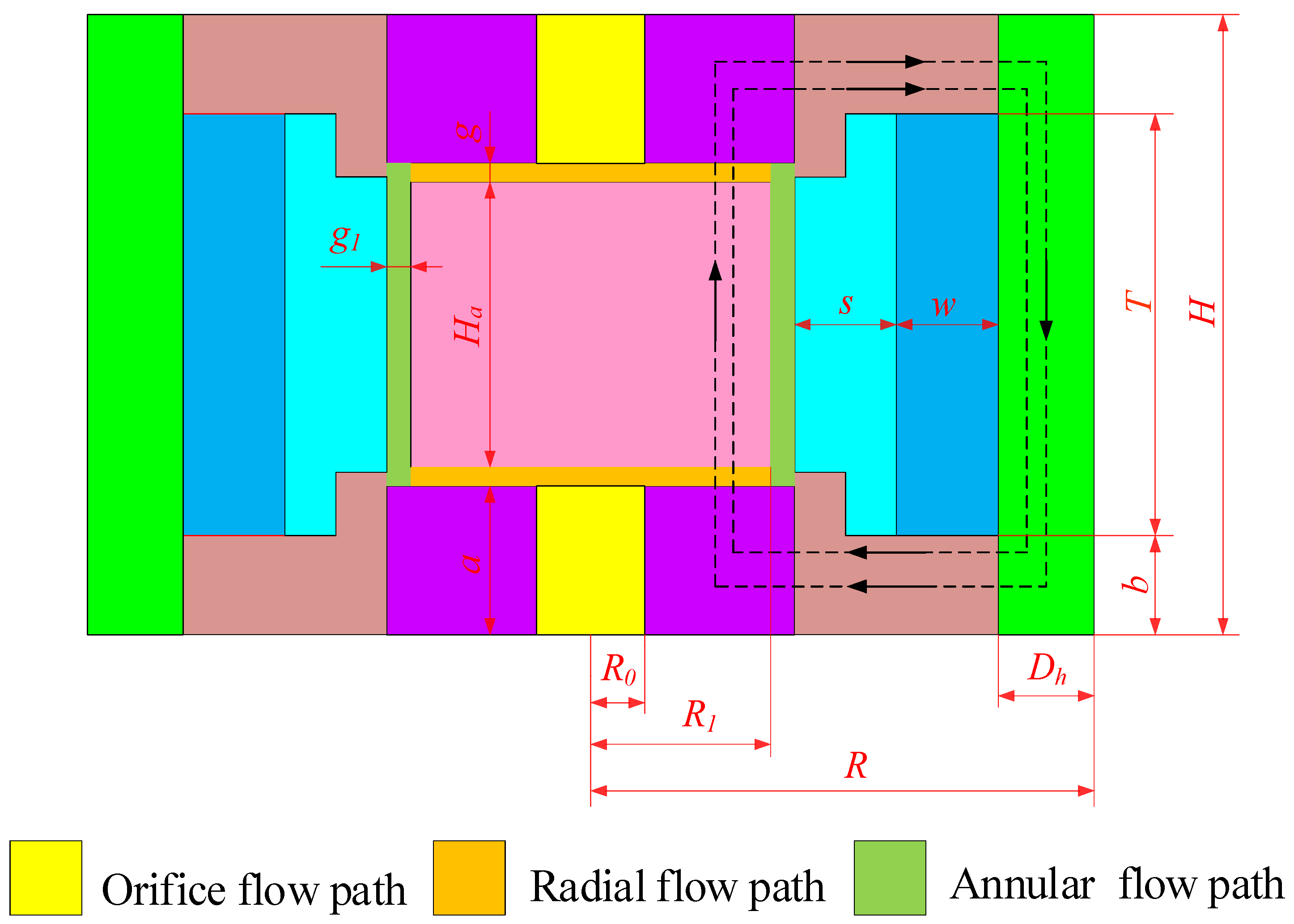
Figure 2 and Figure 3 show the magnetic circuit of the radial MR valve, respectively. The parts and areas through which the magnetic flux lines pass vertically include valve body, magnetic disk, positioning plate, valve spool and two radial damping gaps. Assuming that the magnetic flux lines are uniformly distributed in the magnetic circuit of the radial MR valve and there is no magnetic leakage phenomenon, then the magnetic flux in the loop can be regarded as,
Φ r = Φ l = Φ s t e e l = Φ
where Φ is the total magnetic flux of excitation coil, Φl is magnetic flux through the left end radial disk damping gap, Φr is magnetic flux through the right end radial disk damping gap, Φsteel is magnetic flux of magnetic conductive parts such as valve body, valve spool and positioning plate.
The magnetic circuit of the radial MR valve is divided into eight effective sections, which are respectively the damping gaps of two radial disks, valve body, magnetic disk at the left and right ends of winding wire, positioning plate at left and right ends and valve spool. On the basis of Kirchhoff’s law, the magnetic circuit can be expressed as,
N c I = c H d l = i = 1 8 H i l i
where Nc represents the number of turns of the excitation coil, I is the control current applied in the excitation coil, Hi is the magnetic field intensity in part i of the magnetic circuit, li is the effective length of the magnetic line passing through part i.
The magnetic flux generated by the excitation coil can be expressed as,
Φ = c B d S = B i S i
where Bi denotes the magnetic flux density in part i of the magnetic circuit, S represents the cross sectional area of section part i of the area where the magnetic line passes vertically.
The relationship between magnetic flux density Bi and magnetic field intensity Hi is,
B i = μ 0 μ i H i
where μ0 is the absolute permeability of the air, its value is 4π × 10−7 H/m, and μi is relative magnetic permeability of materials by each region.
The effective regional reluctance Ri in a closed magnetic circuit is expressed as:
R i = l i μ 0 μ s S i
The magnetic resistance of the valve body Rm1 is,
R m 1 = H b μ 0 μ s π [ R 2 ( R D h ) 2 ] = H b μ 0 μ s π [ 2 R D h D h 2 ]
The magnetic resistance of the magnetic disk Rm2 is
R m 2 = R 0 R d l μ 0 μ s 2 π l b = 1 2 π b μ s μ 0 ln   R R 0
The magnetic resistance of the positioning plate Rm3 is,
R m 3 = a 0.5 b μ 0 μ s π [ ( R 1 + g 1 ) 2 R 0 2 ]
The magnetic resistance of the disk damping gap Rm4 is,
R m 4 = g μ 0 μ f π ( R 1 2 R 0 2 )
The magnetic resistance of the valve spool Rm5 is,
R m 5 = H a μ 0 μ s π R 1 2
where R denotes the radius of the valve body, H is the length of the valve body, Dh is the thickness of the valve body, b is the width of the magnetic disk, a the width of the positioning plate, g is the damping gap of the radial disk, g1 is the damping gap of the axial ring, Ha is the width of the valve spool, R1 is the radius of the valve spool, R0 is the radius of the small hole channels, μs is the relative magnetic permeability of the 10# steel with a value of 1000, and μf is the relative permeability of the MR fluid, its value is 2.5 H/m.
Therefore, the total magnetic resistance Rm is:
R m = R m 1 + 2 R m 2 + 2 R m 3 + 2 R m 4 + R m 5
By substituting Equations (3) and (4) into Equation (2), it can be obtained:
N c I = i = 1 8 B i μ 0 μ i l i = i = 1 8 l i μ 0 μ i S i Φ = i = 1 8 R i Φ
Therefore, the magnetic flux density Bi can be regarded as:
B i = Φ S i = N c I S i i = 1 8 R i

2.3. Mathematical Model of Pressure Drop

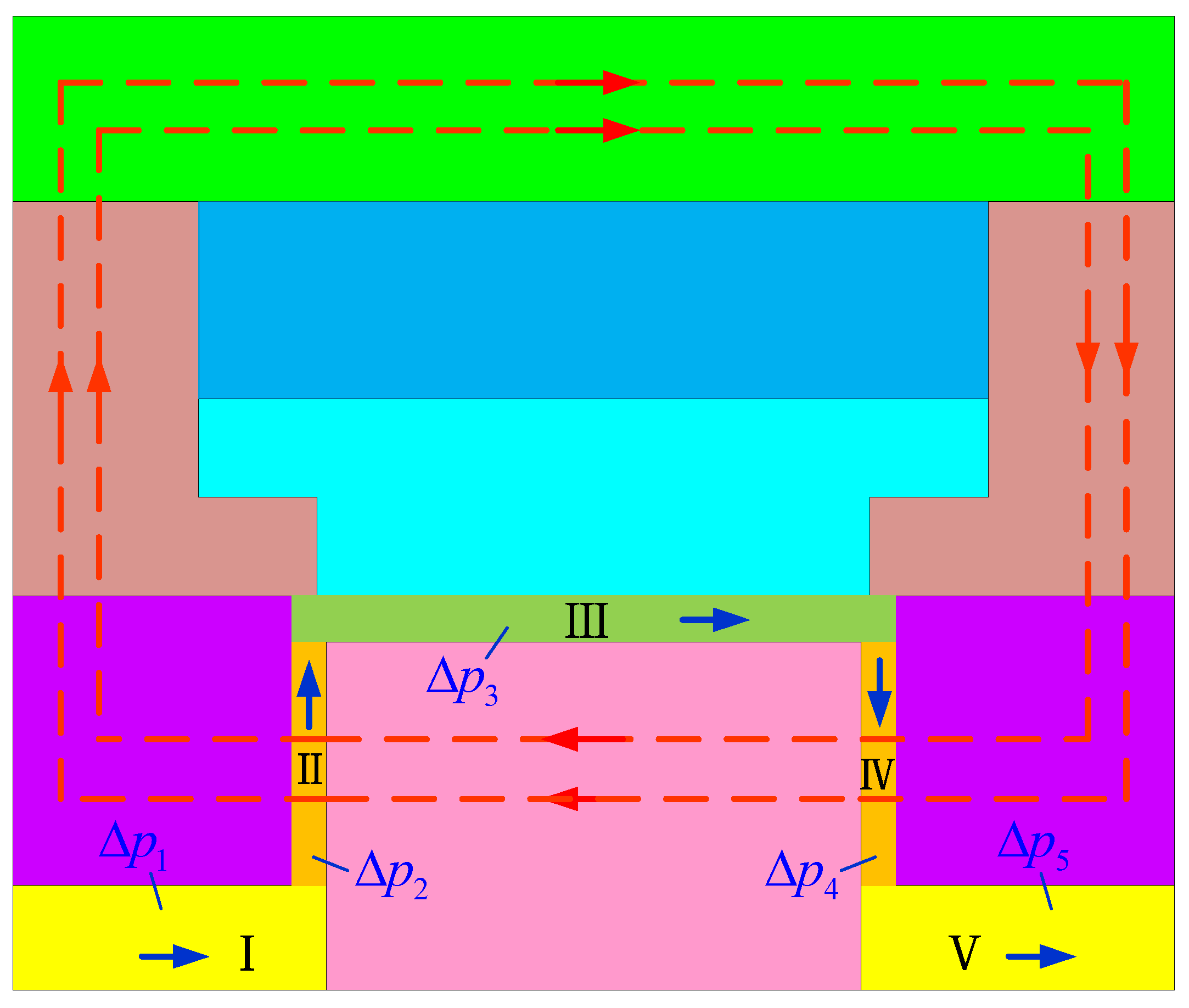
As the proposed single coil radial MR valve is axisymmetric, half of the cross section is illustrated as the research object. As shown in Figure 4, it can be seen that the fluid flow channel of the radial MR valve can be divided into five parts. Among them, I and V are axial circular tube flow of Newtonian fluid, II and IV are radial disk flow of non-Newtonian fluid, and III are axial circular flow of Newtonian fluid.
Therefore, the total pressure drop Δp of the radial MR valve can be represented as,
Δ p = Δ p 1 + Δ p 2 + Δ p 3 + Δ p 4 + Δ p 5 = Δ p η 1 + Δ p η 2 + Δ p τ 2 + Δ p η 3 + Δ p η 4 + Δ p τ 4 + Δ p η 5
where Δp is the total pressure drops, Δpη1, Δpη2, Δpη3, Δpη4 and Δpη5 are the viscosity pressure drop corresponding to channel I, II, III, IV and V, respectively; Δpτ2 and Δpτ4 represents the field-dependent pressure drop corresponding to channel II and IV, respectively.
For the pipe channel with a large aperture of the radial MR valve, MR fluid usually has a small zero field viscosity due to its good fluidity, so the pressure drop generated by the circular tube flow can be ignored. Therefore, according to the symmetry of the valve body structure design, Equation (14) can be simplified as:
Δ p = Δ p η 2 + Δ p τ 2 + Δ p η 3 + Δ p η 4 + Δ p τ 4
As a result, the viscosity pressure drop in the fluid flow channel III can be expressed as
Δ p η 3 = 6 η ( H a + 2 g ) π R 1 g 1 3 q
where q is the system flow rate, L/min; η is the zero field viscosity of MR fluids with a value of 0.8 Pa·s.
The magnetic field passes vertically through channels II and IV, and the fluid flow channel is an effective damping gap channel. Meanwhile, the formed pressure drop originates from the sum of viscosity pressure drop Δpη and field-dependent pressure drop Δpτ.
The viscosity pressure drop can be expressed as:
Δ p η 2 = Δ p η 4 = 6 η q π g 3 ln R 1 R 0
The field-dependent pressure drop can be regarded as,
Δ p τ 2 = Δ p τ 4 = c ( R 1 R 0 ) g τ y
where τy represent the dynamic shear yield stress, c is the correctional coefficient, dimensionless, with a value of 2~3.
In conclusion, the theoretical expression formula of the total pressure drop Δp of the two-stage radial flow MR valve can be expressed as:
Δ p = 6 η ( H a + 2 g ) π R 1 g 1 3 q + 12 η q π g 3 ln R 1 R 0 + 2 c R 1 R 0 g τ y
The ratio K of the field-dependent pressure drop Δpτ to the viscosity pressure drop Δpη is called the adjustable coefficient, the adjustable coefficients K of the MR valve can be expressed as:
K = Δ p τ Δ p η = c π ( R 1 R 0 ) τ y g 2 6 η q ln R 1 R 0 + 3 η H a g 3 R 1 g 1 3

3. Simulation Analysis of Magnetic Field and Dimensional Parameters of the Radial Mr Valve with Single Excitation Coil

3.1. Working Characteristics of MR Fluids

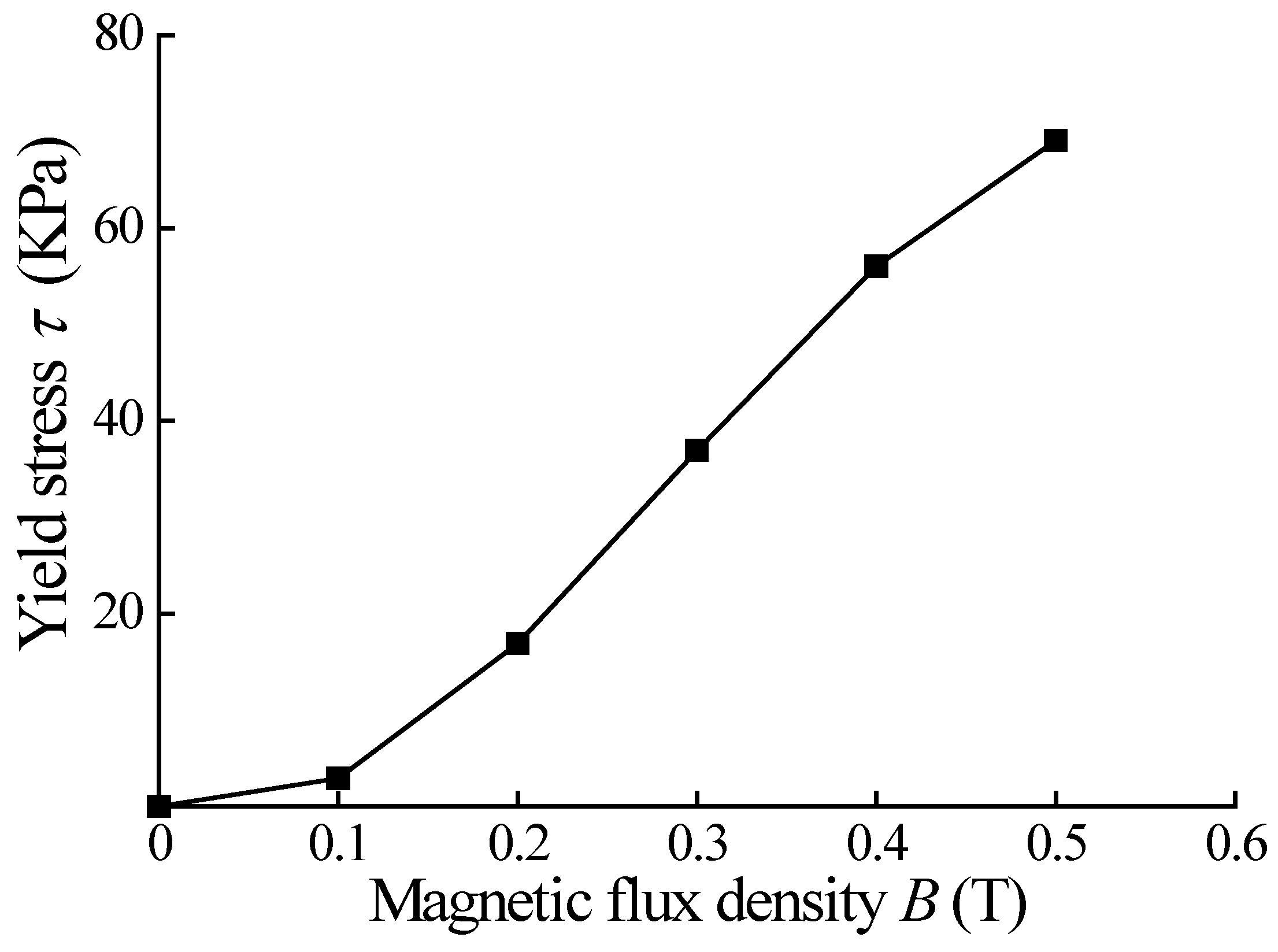
The MR fluid with type of MRF-J01T is provided by the Chongqing Instrument Material Research Institute in China [30]. The relationship between magnetic flux density B and shear stress τ is nonlinear, as shown in Figure 5. By using the least square method, the τ-B curve of the MR fluid is fitted by polynomial, and the relationship between shear yield stress and magnetic flux density at the damping gap of radial disk is obtained,
τ y = a 1 × B 3 + a 2 × B 2 + a 3 × B + a 4
where a1 = −984.27 kPa/T3, a2 = 865.39 kPa/T2, a3 = −48.46 kPa/T, and a4 = 0.018 kPa.
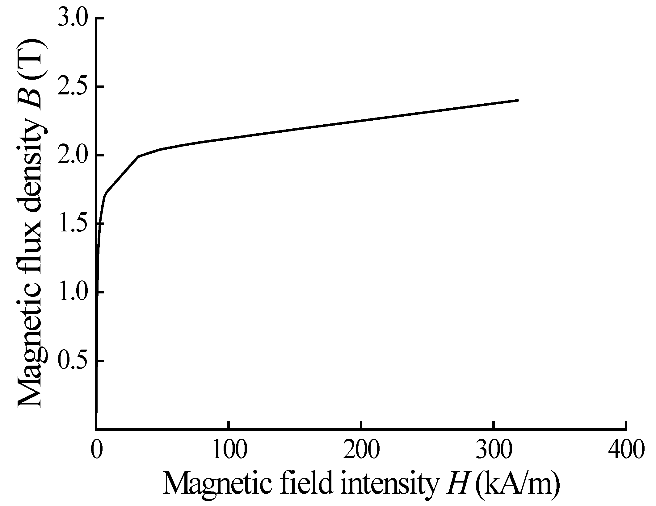
Taking into account relevant factors, 10 # steel is used as the material of magnetic conductive parts in this paper, and its B-H magnetization characteristic curve is shown in Figure 6.

3.2. Electromagnetic Field Simulation of MR Valve

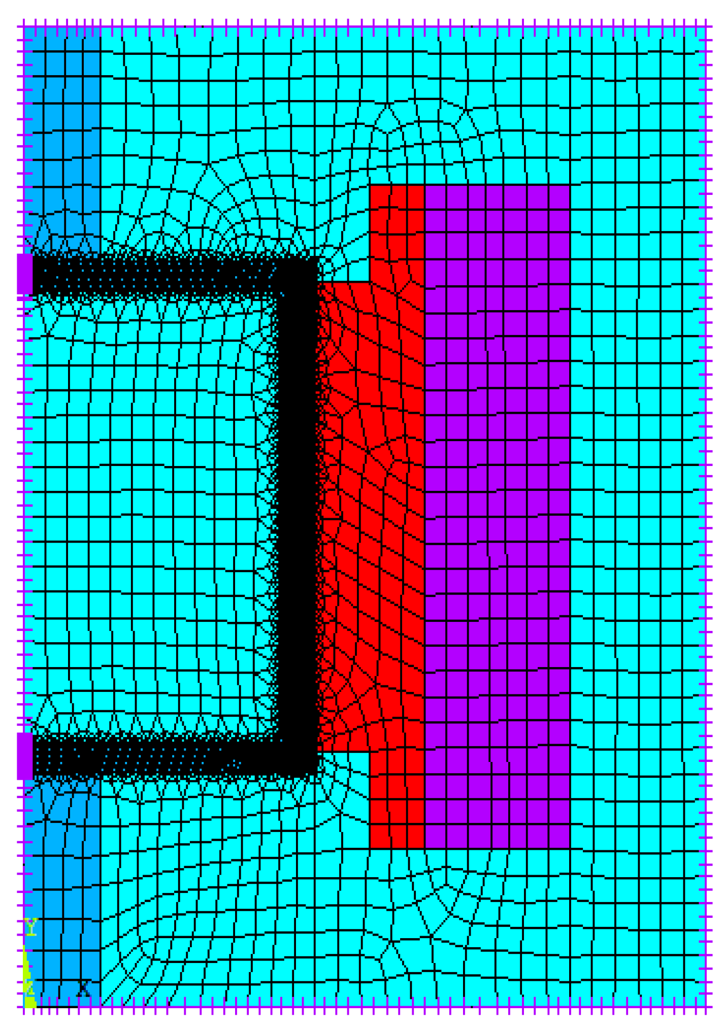
Considering the calculation scale and accuracy, the magnetic field simulation is analyzed by using the axisymmetric two-dimensional (2D) model. Neglecting the influence of the end cover, sealing ring and other structures on the magnetic field, adopting the top-down modeling method, the two dimensional simplified simulation geometry model of the radial MR valve is shown in Figure 7. Choosing a level 1 SmartSize intelligent mesh division and a quadrilateral mesh structure element to apply a magnetic flux line parallel boundary without magnetic leakage, and current density is applied to the coil element to input the excitation load, the division of different colors represents the material with different attributes, the final finite element model is shown in Figure 8.
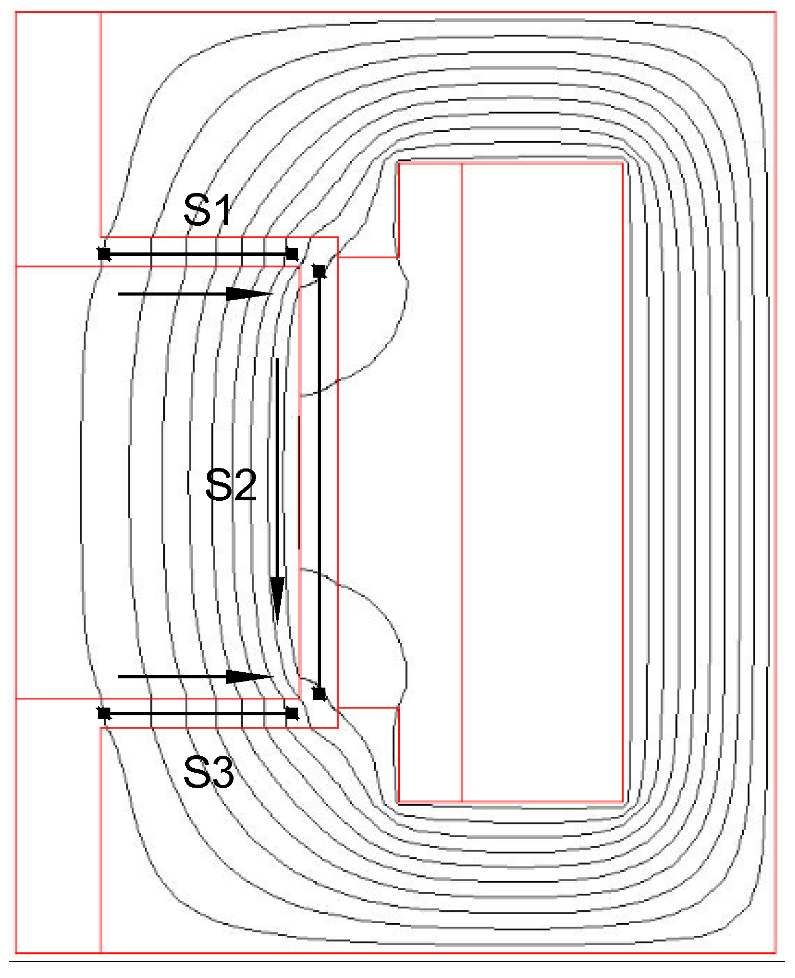
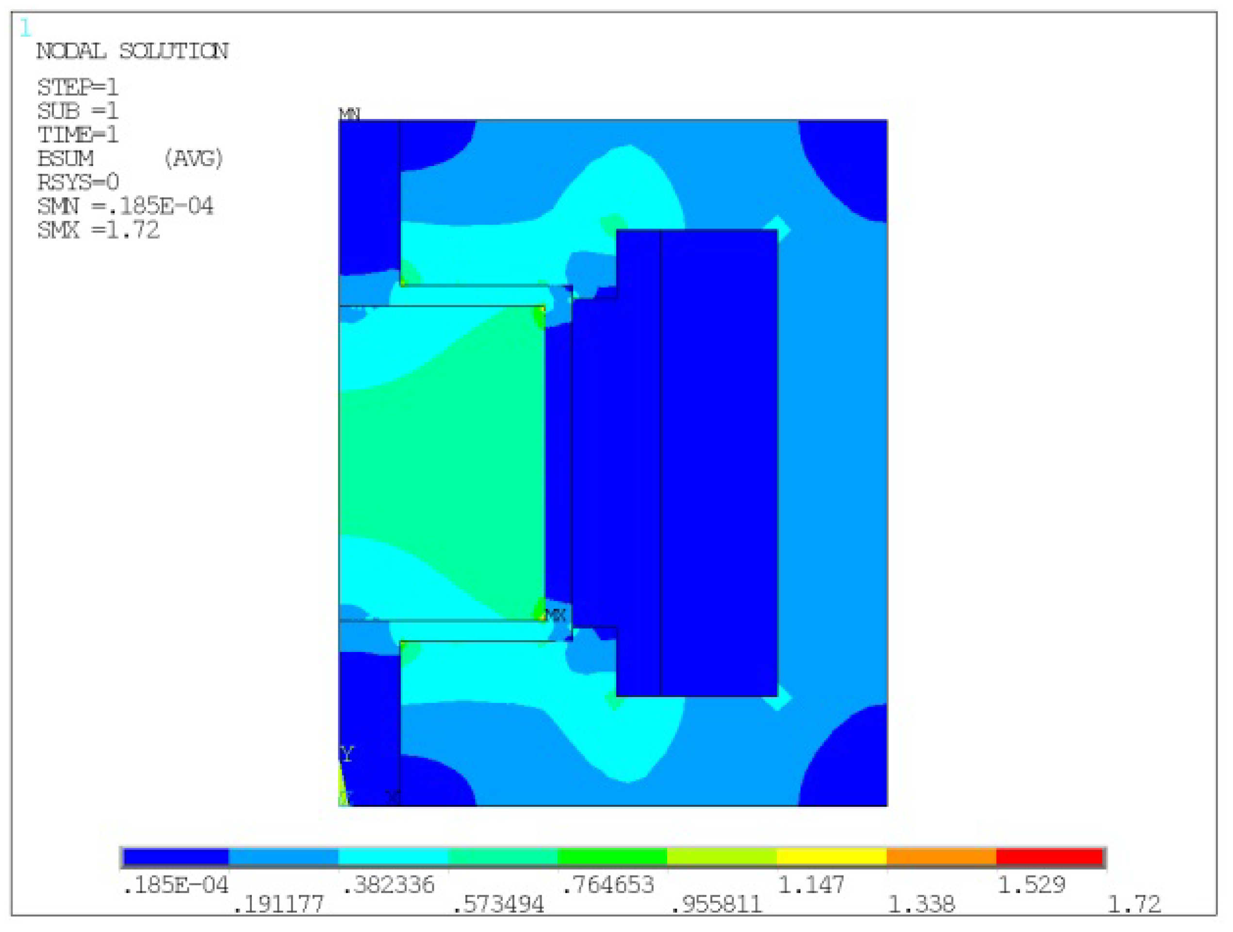
On the basis of setting the structure size parameters, the current of the excitation coil is set to 1 A, and the corresponding magnetic field simulation results are obtained as shown in Figure 9 and Figure 10, respectively. Figure 9 shows the magnetic flux lines distribution of the radial MR valve. It can be seen that the magnetic flux line passes through the radial fluid flow path, and its direction is basically perpendicular to the direction of fluid flow. Moreover, the closer the magnetic flux line in the middle of the spool, the more vertical the magnetic flux line is to the effective channel path. Figure 10 shows the magnetic flux density contour of the radial MR valve, different colors in the picture represent the magnetic flux density of different region in the model, it can be obtained that the maximum magnetic flux density of the MR valve is about 1.72 T.
Two paths S1 and S3 are defined in the radial flow channel of the MR valve, and their orientations are shown by the arrows in Figure 9. The distribution of magnetic flux density in two defined radial path S1 and S3 is shown in Figure 11, and the magnetic flux density in both paths is basically the same. Meanwhile, the magnetic flux density is concentrated in the middle segment of each corresponding path and gradually weakens towards both ends of the path.
The curve in Figure 11 is only designed to show more conveniently the distribution of magnetic flux density with path in the effective fluid flow channel of the radial MR valve. However, in order to better compare and calculate the relevant research tasks, the influence of excitation current, structure size and other parameters on magnetic field is studied, the average magnetic flux density in the damping gap is defined as,
B ¯ = B   d l   d l
where l is the displacement in the direction of liquid flow. The y-direction component of the magnetic flux density on the model is the effective quantity. In order to further improve the average magnetic flux density in the effective channel, the reduction of the x-direction component becomes the research focus, which also provides theoretical support for the next step of MR valve size optimization.
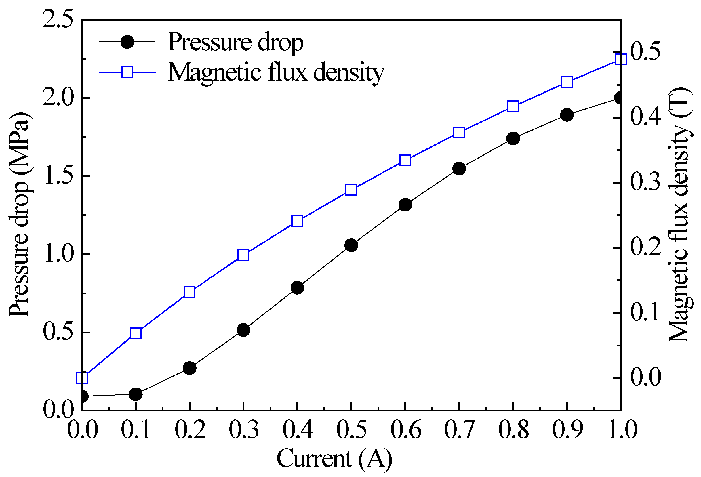
Figure 12 shows the variation curve of magnetic flux density and pressure drop of the radial MR valve under different current. It can be seen that with increase of the current, the average magnetic flux density in the damping gap increases, and the shear yield strength of the MR fluid also increases, which makes the pressure drop of the MR valve increase. In addition, the figure also shows that the pressure drop can produce about 2 MPa when the input current is 1 A.

3.3. Effect of Dimensional Parameters on Performance of Magnetic Flux Density and Adjustable Coefficient

To study the effect of the disk damping gap g on the performance of magnetic flux density and adjustable coefficient, the constraint conditions are as follows:
H a = H 2 g 2 a
On the basis of the above conditions, the other parts size is not changed, only the disk damping gap is changed to analyze the effect of MR valve performance. As can be seen from the simulation results in Figure 13, with the increase of the disk damping gap, the magnetic flux density in the gap decreases. This is because with the increase of the gap size, the magnetic resistance at the damping gap of the disk in the magnetic circuit increases greatly; with the increase in gap size, the total pressure drop decreases, while the adjustable coefficient rises. The reason is that the viscosity pressure drop is inversely proportional to the third square of dimension g, while the field-dependent pressure drop is inversely proportional to the first square of dimension g, and the viscosity pressure drop decreases faster than the field-dependent pressure drop.
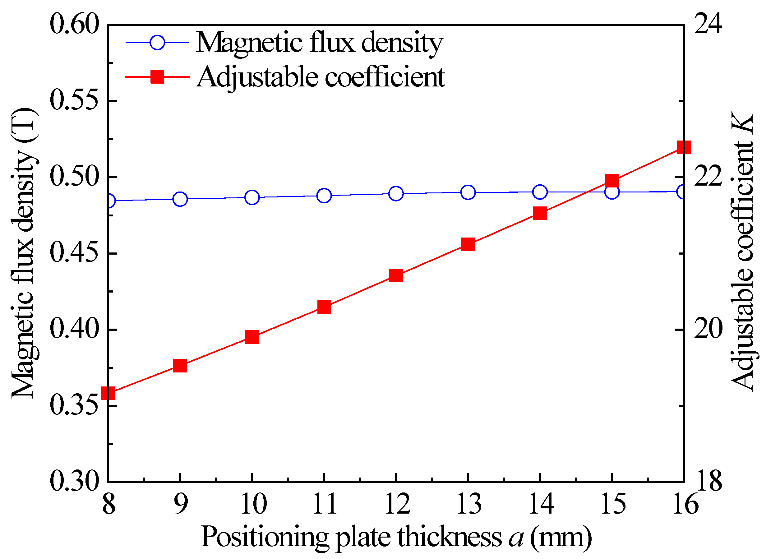
In order to study the effect of the thickness of the positioning plate on the performance, the influence of the thickness of the positioning plate on the performance of the MR valve is analyzed under the constraint of Equation (23). As can be seen from the simulation results in Figure 14, with the increase of the thickness of the positioning plate a, the magnetic flux density in the damping gap of the disk is basically unchanged, but the adjustable coefficient increases. As the total reluctance in the magnetic field loop is insensitive to the thickness of the positioning plate, the magnetic flux density is basically unchanged, and the field-dependent pressure drop is unchanged too, but with the increase of the thickness of the positioning plate, the viscosity pressure drop decreases, which leads to the increase of the adjustable coefficient of the valve as a whole.
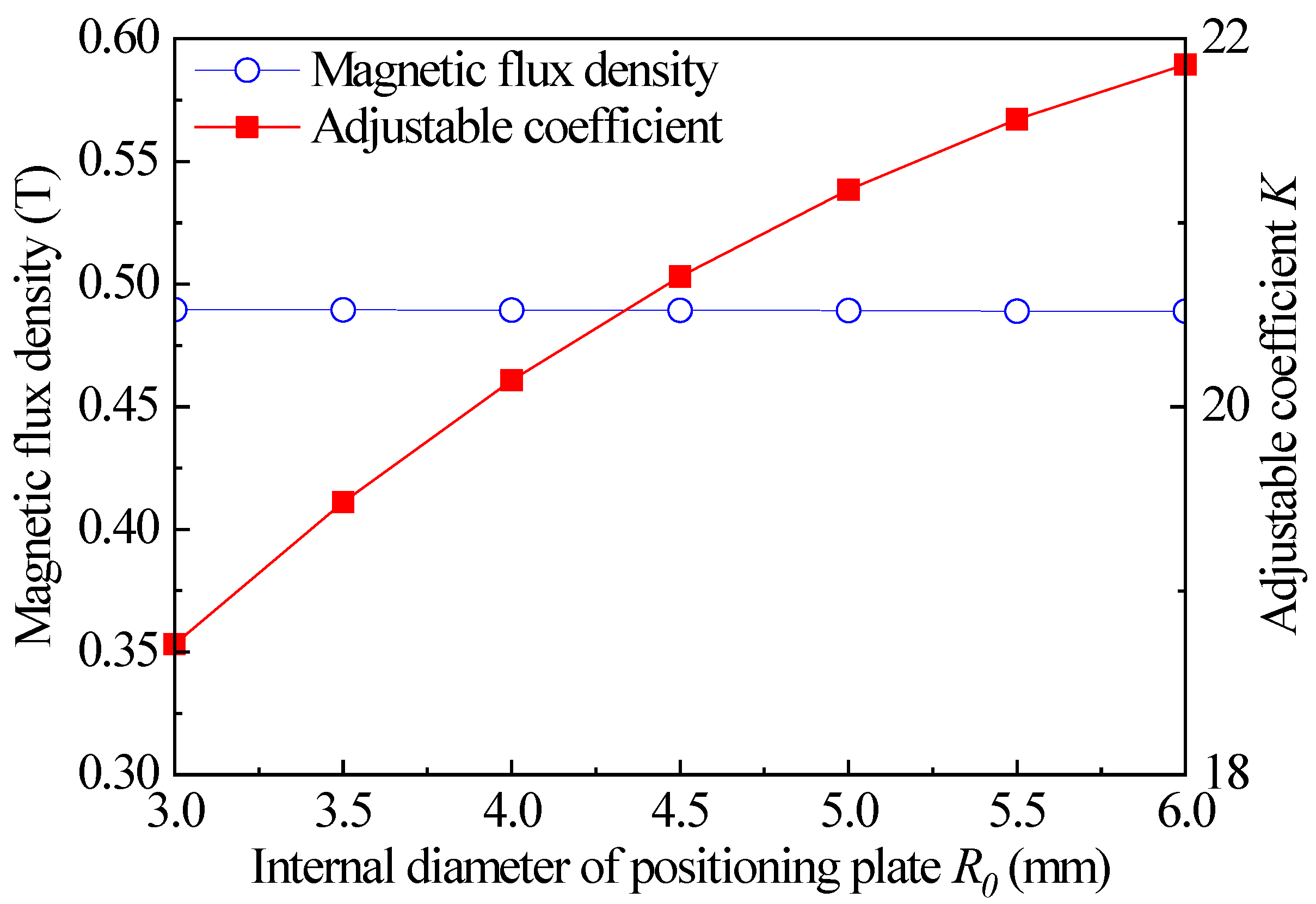
Figure 15 shows the influence of inner diameter R0 of the positioning plate on the valve performance, only the inner diameter size of the positioning plate is changed, while the other sizes remain unchanged. With increase of the inner diameter R0 of the positioning plate, the magnetic flux density in the damping gap of the disk is basically unchanged, but the adjustable coefficient increases. Since the total reluctance of the magnetic field circuit is insensitive to the inner diameter R0 size of the positioning plate, the magnetic flux density is basically unchanged, but with the increase of the inner diameter of the positioning plate, the viscous pressure drop decreases faster than the field-dependent pressure drop. As a result, the overall adjustable coefficient of the valve increases.

4. Optimization of Radial MR Valve with Single Excitation Coil

4.1. Optimization of Controlled Pressure Drops

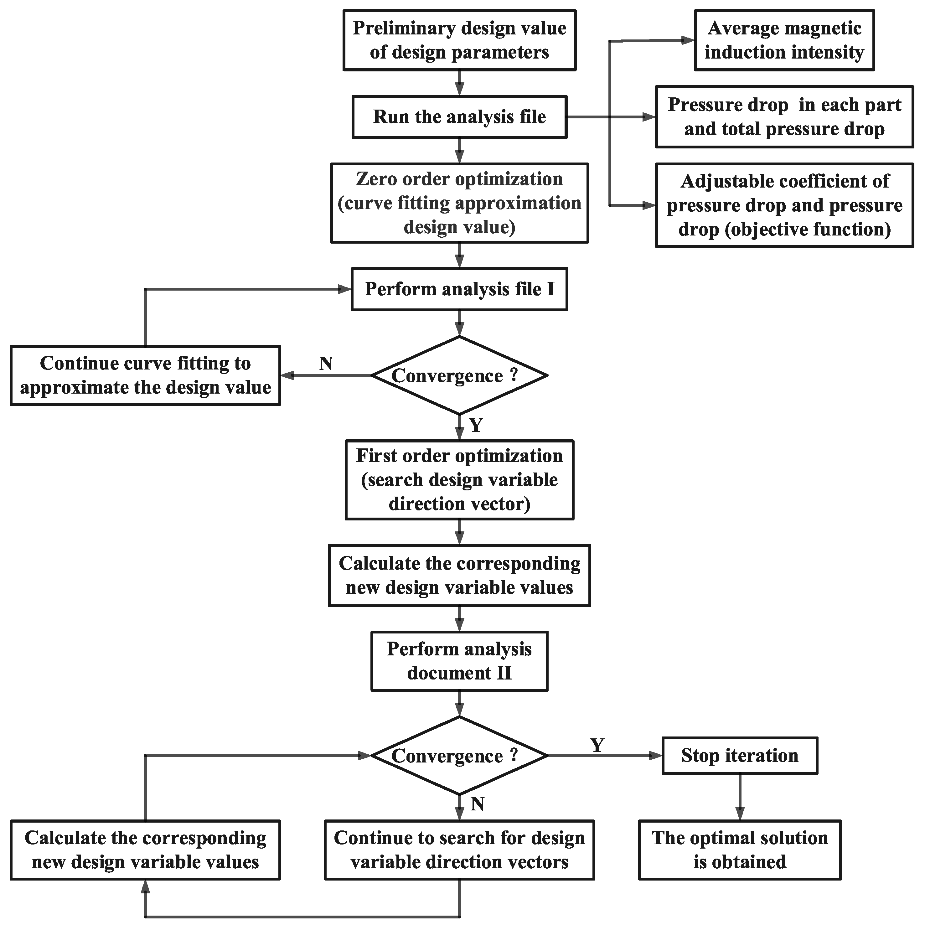
It is easy to generate local optimal solution results when first-order optimization method is used for simulation solution in the ANSYS software, and zero-order optimization method has low solution accuracy. Therefore, the above two optimization tools are comprehensively used for optimization. First, the zero-order method is used to determine the approximate region of the optimal solution, and then the first-order method is used to accurately solve the optimal parameters. This method can obtain accurate results, as well as reduce the iteration time of the optimization algorithm, in order to obtain the best technical scheme more quickly; its optimization process is shown in Figure 16. In the preliminary optimization design, to avoid obtaining the local minimum value on the unreasonable design space, the zero-order method is first used to conduct curve fitting to approximate the reasonable design sequence. At the end of the loop, the first-order method is run with the convergence value as the starting point, the penalty function is added to obtain the unconstrained objective function. The new design variable is calculated by searching the direction vector of the design variable, and the optimal solution is finally obtained after several iterations.
In this paper, adjustable coefficients and pressure drop are used as objective functions. Multi-objective optimization is carried out on the objective function by setting the weight coefficient in the ANSYS software, as the MR valve with excellent performance should have a wide adjustable range of pressure drop in addition to higher pressure drop. The ANSYS software can only be used to optimize the minimum value of the single objective, so it is necessary to rebuild the optimization objective function. Considering the pressure drop and adjustable coefficient of the MR valve at the same time, the linear weighting method is used to set up the index weight coefficient to construct the objective function as,
f = p τ p τ λ 1 + K K λ 2
where pτ* represents field-dependent pressure drop of the initial radial MR valve, pτ represents field-dependent pressure drop of the optimal radial MR valve, K* is adjustable coefficient of the initial radial MR valve, K is adjustable coefficient of the optimal radial MR valve, λ1 means the weight factor of the field-dependent pressure drop, and λ2 means the weight factor of adjustable coefficient.
The performance of the valve body is optimized under the same volume, that is, without changing the dimension size of the radial MR valve, the excitation current is 1 A, and its objective function is optimized. In addition, the effect of the ring damping gap on the performance is ignored, selecting the optimum design variable of the radial MR valve performance as,
{ 1 g 2 3 R 0 6 12 R 1 20 8 a 16 6 D h 10 25 T 40
State variables as,
B ¯ 0.3 T
In addition, there are the following geometric constraints in the MR valve size:
{ H a = H 2 g 2 a w = R D h R 1 g 1 s b = 0.5 ( H T )
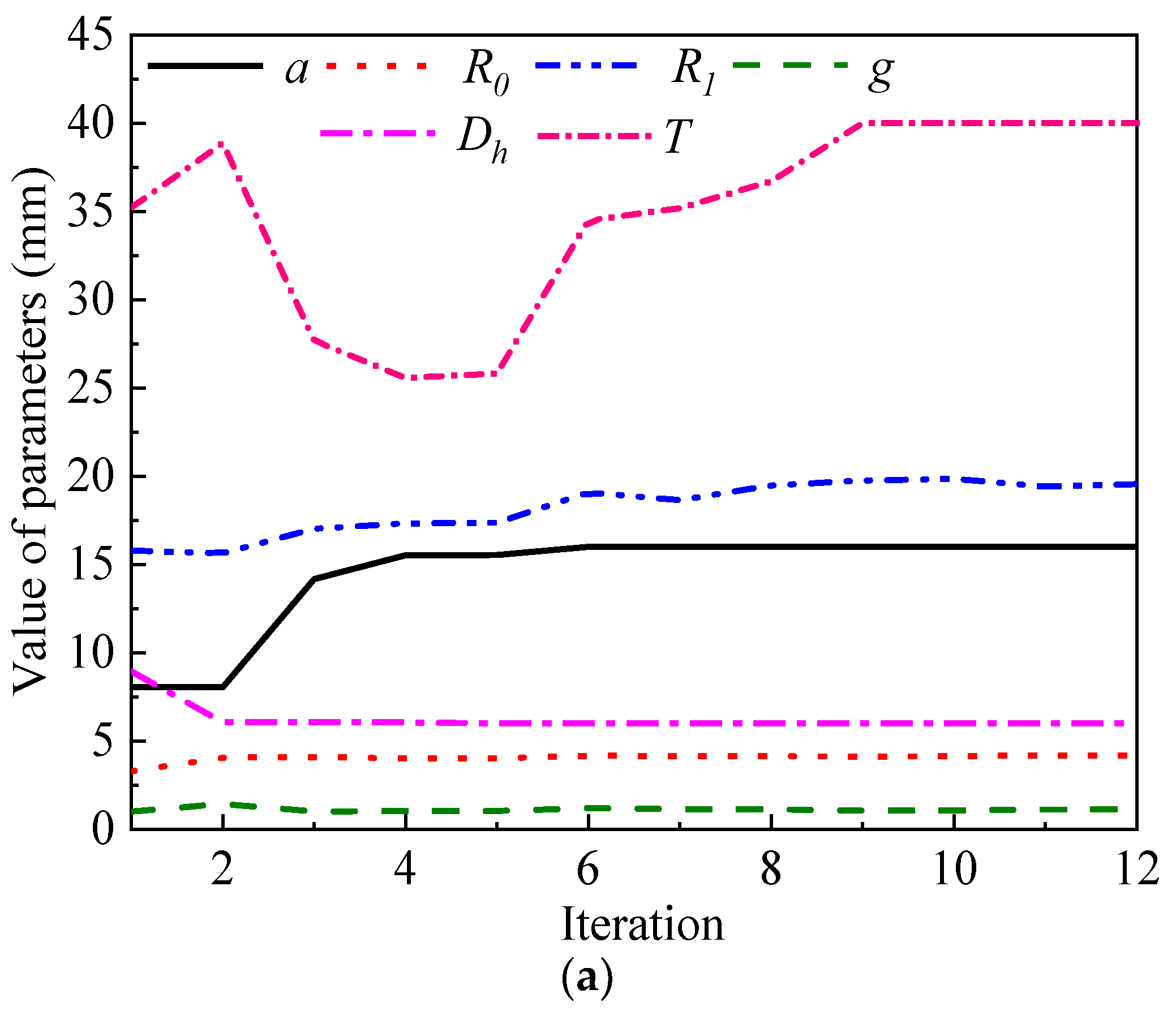
Considering the requirement of radial MR valve comprehensive performance for the adjustable coefficient and field-dependent pressure drop, three different weight coefficients λ1 = 1 and λ2 = 0, λ1 = 0 and λ2 = 1, λ1 = 0.75 and λ2 = 0.25 are set and optimized, respectively. Figure 17 is an iterative diagram of the optimization design parameters of the radial MR valve associated with the weight coefficient λ1 = 0.75 and λ2 = 0.25 as the objective function parameters. Figure 17a shows design variable parameters gradually stabilize after initial large amplitude changes, because the early zero order optimization obtains the approximate region of the small range optimal solution within the upper and lower limits of the initial variable design, on the basis of the first-order optimization. Figure 17b shows the optimization process goes through 12 iterations, and the objective function obtains the minimum value in the 12th iteration, that is, the optimal result is obtained. Figure 17c shows variation curve of pressure drop and adjustable coefficient in 15 iterations, and the pressure drop and adjustable coefficient parameters gradually stabilize after initial large amplitude changes. The final optimization results are shown in Table 1 and Table 2.
Observing Table 1 and Table 2, when the field-dependent pressure drop is only taken as the optimization goal, the adjustable coefficient of the optimal valve decreases more than that of initial one although the pressure drop value increased greatly. In the scheme with the adjustable coefficient as the optimization objective, the adjustable coefficient increases from 20.71 to 36.51, but the field-dependent pressure drop decreases by 394.6 kPa. If the weight coefficient is λ1 = 0.75 and λ2 = 0.25, the radial MR valve sacrifices a small amount of adjustable coefficient performance, but its field-dependent pressure drop pτ is greatly improved. Therefore, this optimized data with value of λ1 = 0.75 and λ2 = 0.25 is adopted to process the experimental radial MR valve.

4.2. Optimal Results Analysis

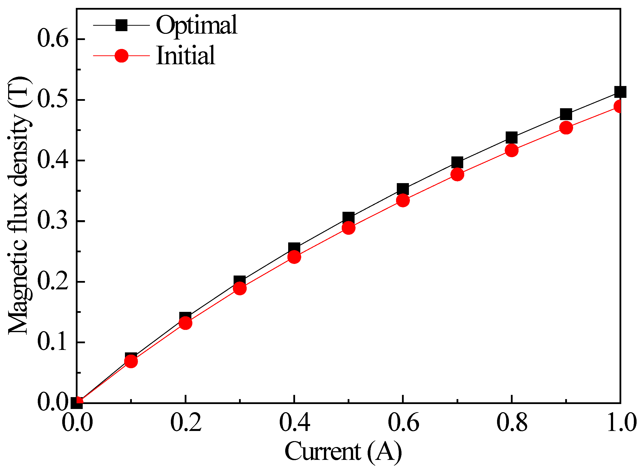
Figure 18 shows the relationship between the average magnetic flux density and the applied current for the initial and optimal radial MR valve. It can be seen that the average magnetic flux density in the effective damping gap increases with the increase of excitation current. But under the same current, the average magnetic flux density in the optimal MR valve channel is larger than that in the initial parameter state. When the current is 1 A, the average magnetic flux density in the optimal MR valve channel can reach about 0.5 T. It can be seen that the magnetic flux density in the damping gap of the initial and optimal radial MR valve is close, which shows that the initial structure design and its parameters are basically reasonable.
The variation of the pressure drop of the initial and optimal MR valve is shown in Figure 19. Observing the figure, the pressure drop of the optimal valve is obviously increased compared with that initial one. When the input current is 1 A, compared with the 1.5 MPa pressure drop of the initial MR valve, the pressure drop of the optimal MR valve can reach about 4 MPa, and increase nearly 2.7 times, which shows a better optimization effect.

5. Experimental Test and Analysis of Radial MR Valve

5.1. Prototype of Radial MR Valve with Single Excitation Coil

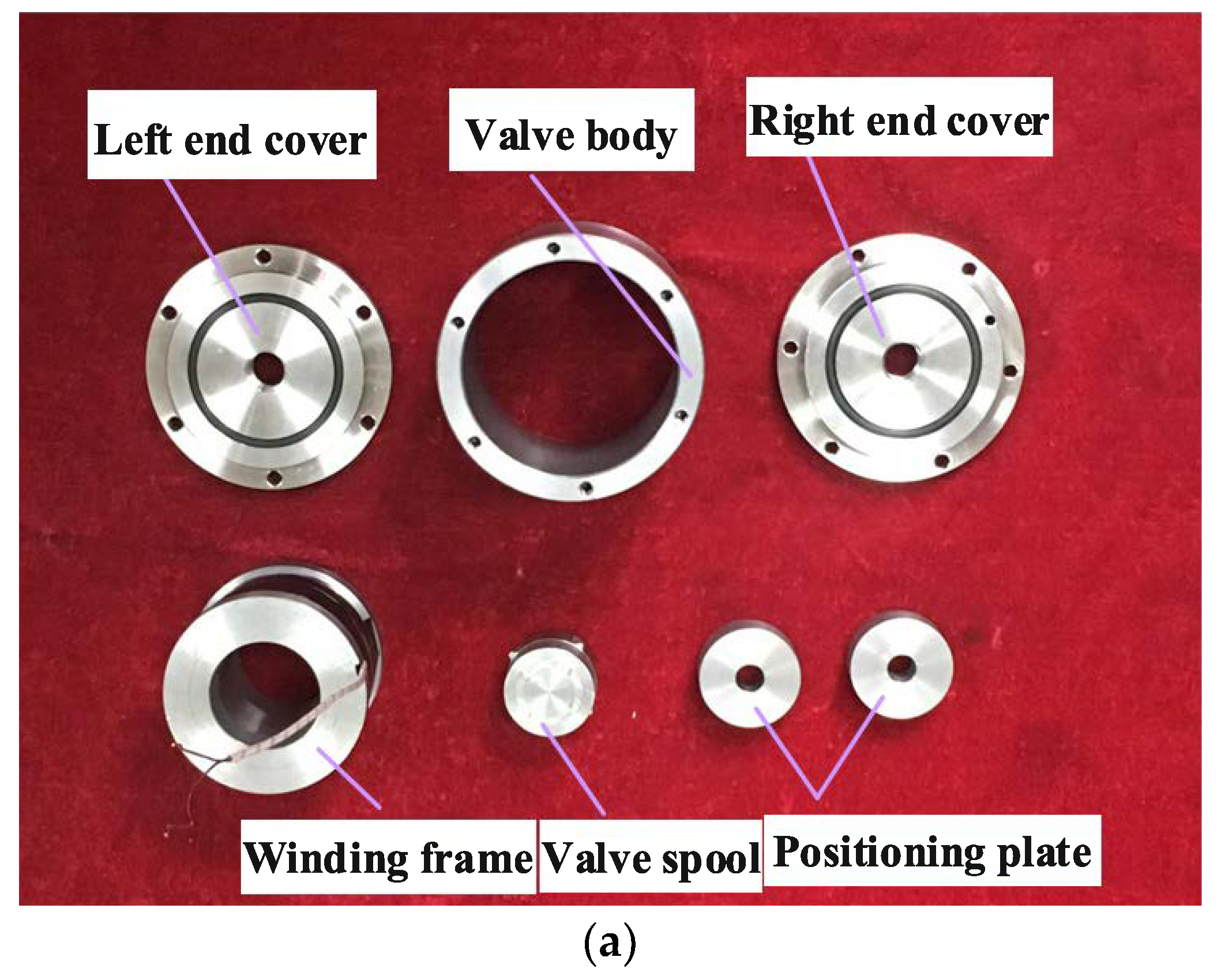
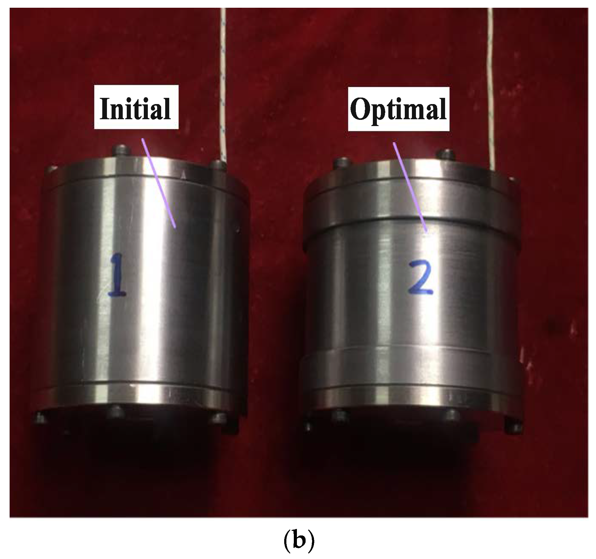
On the basis of structure design and simulation analysis, the size parameters of the proposed valve were optimized and improved, the simulation results show that the optimal MR valve had better performance and more reasonable size setting. According to the relevant size optimization values in Table 2, the optimal radial MR valve was manufactured. At the same time, in order to reflect the excellent practical effect of the optimal valve more clearly, the initial valve was also fabricated according to the initial design dimensions. Figure 20 is the prototype of the initial and optimal valve.

5.2. Performance Test System of Radial MR Valve

The experimental test system is shown in Figure 21, which includes hydraulic drive system, and LabVIEW control system, respectively. The power unit in the hydraulic drive system is composed of motor and gear pump, in which the flow rate is 4 L/min. LabVIEW control system is mainly composed of pressure sensor, acquisition card, host computer and power supply.
The relief valve I is used as a safety valve, which is connected between the gear pump and the inlet of the MR valve. The relief valve II is adopted to simulated load for the test system, connection in the MR valve between exports and return oil tank. Power supply I supplies power to the excitation coil of the valve, power supply II is adopted respectively for pressure sensor I and II power supply. The pressure sensors I and II in the control system detect the inlet and outlet pressure of the valve, respectively. The data acquisition card collects the pressure data detected by pressure sensor I and II in real time, and transmits the collected pressure data to the computer control interface.

5.3. Pressure Performance Test of the Radial MR Valve

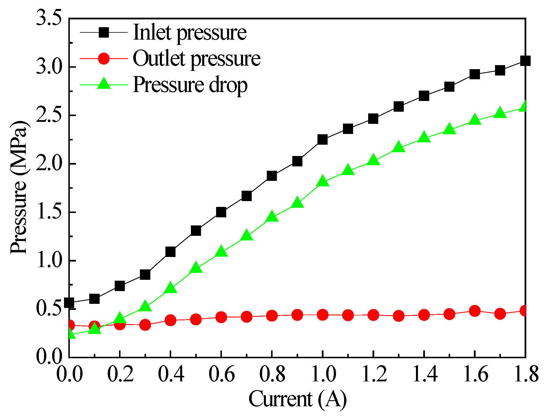
When the load applied to the radial MR valve was fixed, the excitation current of the radial MR valve was adjusted by moving the power supply, the excitation current increases gradually from 0 A to 1.8 A. Figure 22 shows the test results of the optimal valve, with the increase of excitation current, the inlet pressure of the optimal radial MR valve increases according to certain rules, the steady pressure of the relief valve in the system makes the outlet pressure basically stable and the total pressure drop increases accordingly. In Figure 22, the total pressure drop of the optimal radial MR valve increases with the increase of excitation current, which was consistent with the trend of simulation results.
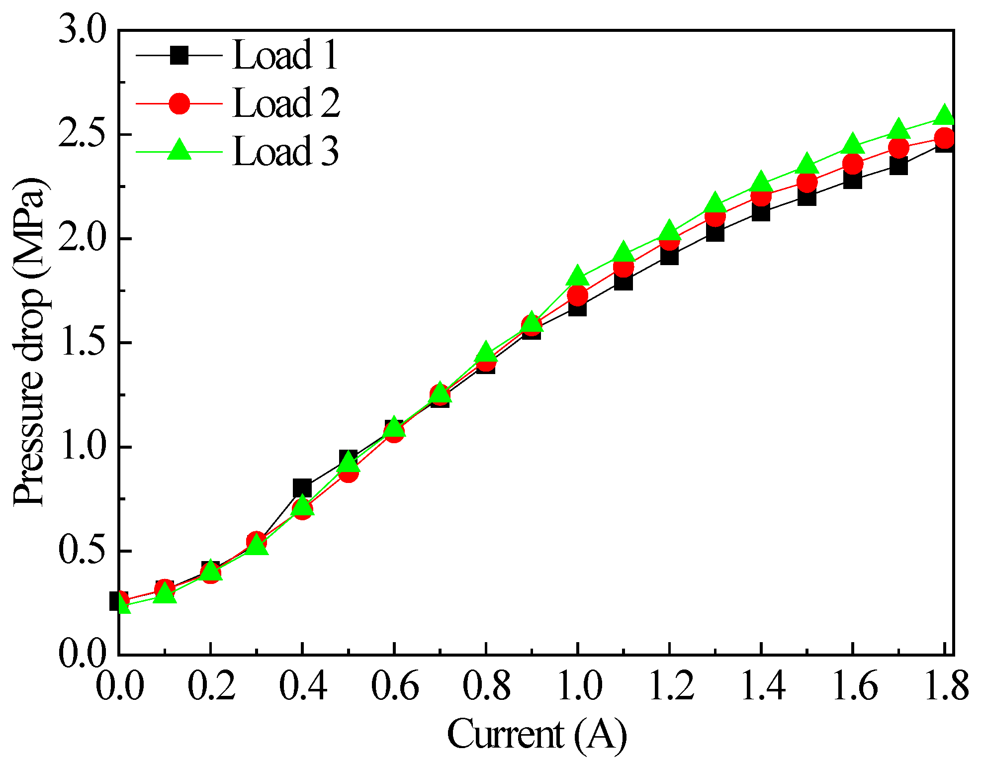
In this experiment, the opening degree of relief valve can be adjusted by controlling the number of turns of the relief valve II handle to simulate the load change, and the variation of pressure drop with current under different loads is tested respectively. The initial position of the handle is defined as load condition 1, at which the opening degree is the maximum. The rotating handle decreases the opening degree and the load increases. Two turns are defined as the load condition 2, and four turns are defined as the load condition 3. Figure 23 describes the variation of the pressure drop under different loads and currents for the optimal radial MR valve. The pressure drop of the optimal valve changes with the current, and after applying three different loads, it is basically coincident. Therefore, it can be concluded that the load has little influence on the pressure drop, and the radial MR valve could be used for the control parts under various load conditions.

5.4. Response Performance Test of the Radial MR Valve

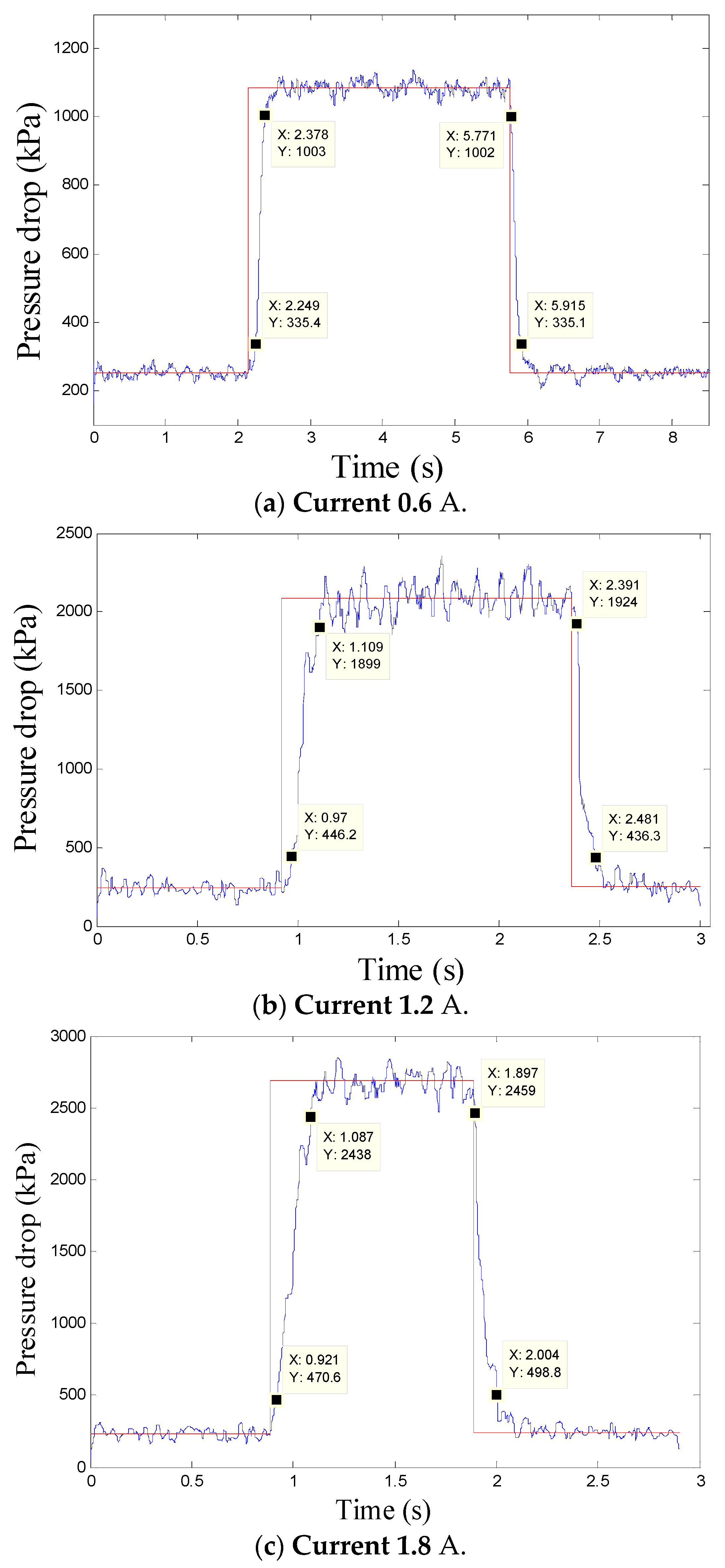
In the experiment, the acquisition points of each channel were set as 10 and the sampling frequency was set as 1000. At the same time, the rising response time of the radial MR valve was defined as the time when the pressure drop increases from the initial value to 90% of the maximum pressure drop of the same current after the current was turned on, and the falling response time was the time lost when the pressure drop from the initial value to 10% of the maximum pressure drop of the same current.
In order to understand the response performance, a step signal was applied to the excitation coil of the initial and optimal radial MR valve, and the experimental data were processed by MATLAB. Figure 24 and Figure 25 shows pressure drop variation of the initial and optimal radial MR valve with time, the X axis in the figures represent different time processes, and the Y axis represent the pressure drop of different time points. It is clear seen that the variation trend of different current response time of the initial and optimal radial MR valve was consistent. Table 3 shows the response time of the initial and optimal valve. The dynamic response time of both MR valves is reduced dramatically by applying excitation current. The rising response time of the initial MR valve increased from 71 ms at the applied current of 0.6 A to 119 ms at the applied current of 1.8 A. The rising response time of the optimal MR valve increased from 129 ms at the applied current of 0.6 A to 166 ms at the applied current of 1.8 A. When the applied current was 0.6 A, the rising response time of the optimal MR valve increases by 81.69% compared with that initial MR valve, while the applied current was 1.8 A, the rising response time of the optimal MR valve increases by 39.50% compared with that initial MR valve. The response time of the radial MR valve increases gradually, which is because the pressure drop increases with the increase of current.
The results show that the average response time of the initial radial MR valve is about 90 ms and the optimal radial MR valve is about 130 ms. Though response time of the MR fluid was 1~2 ms, the response time of MR valve in test rig was still relatively long. This is due to the long response time of the motor and gear pump in the hydraulic system, and after cutting off the power supply, the residual magnetic field in the radial MR valve is significant, which prolong the response time of the MR valve.

5.5. Experimental Analysis of Dynamic Performance of Radial Mr Valve Controlled Cylinder System

5.5.1. Dynamic Performance Test System of Radial Mr Valve Controlled Cylinder System

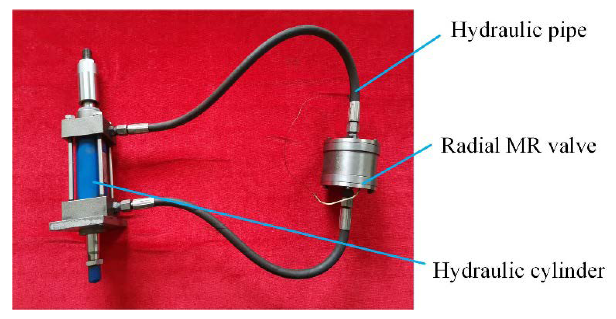
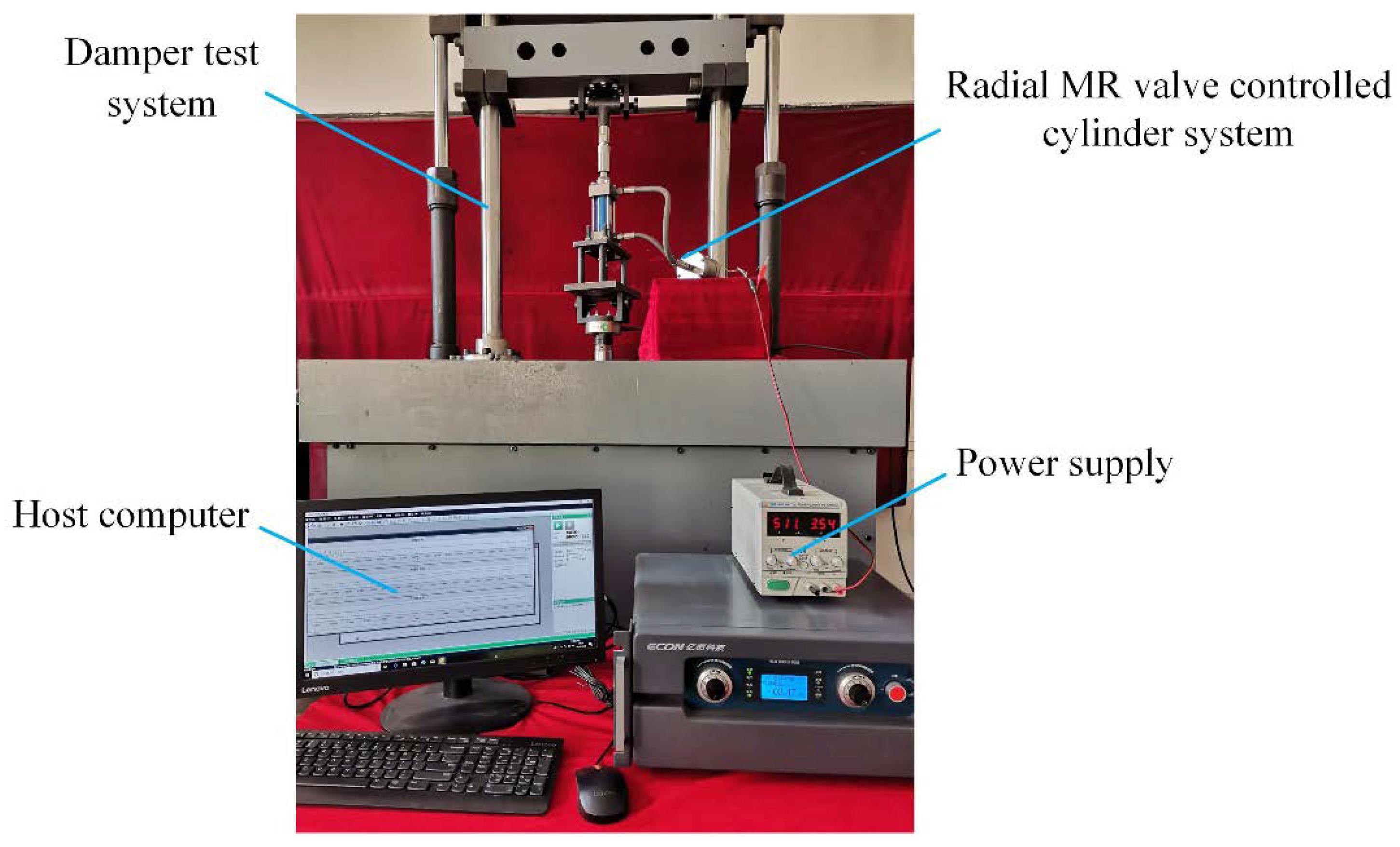
Figure 26 shows the established radial MR valve controlled cylinder system, and Figure 27 is the experimental test rig. In the system, the lower end of the hydraulic cylinder is fixed on the fixture of the damper test system, and the upper end is connected with the power rod and the sensor. The power supply is used to supply the radial MR valve, the damper test system can provide different vibration excitation for the hydraulic cylinder, and the damping force data can be transmitted to the host computer in real time by the sensor.

5.5.2. Dynamic Performance of the Optimal Radial Mr Valve Controlled Cylinder System

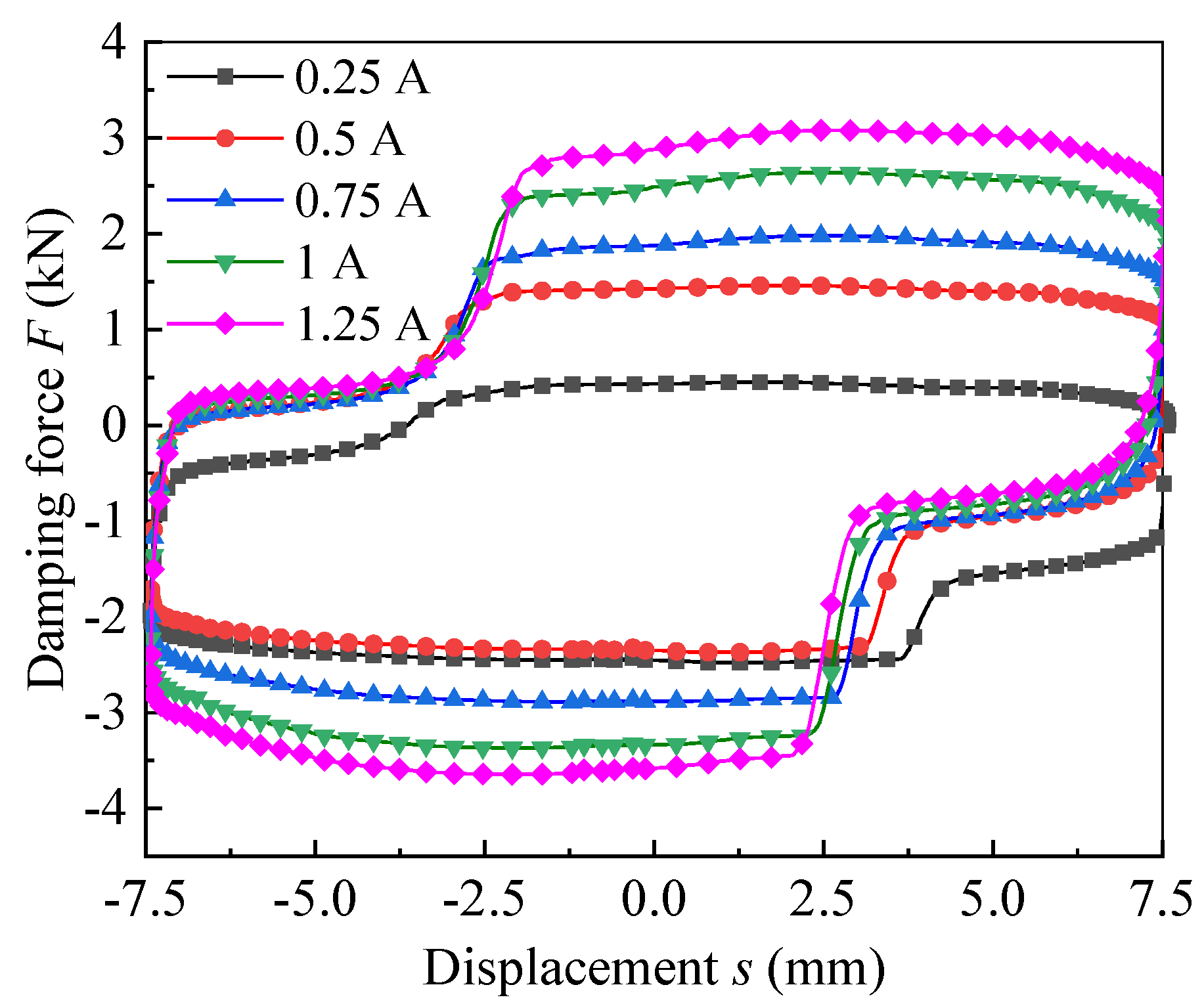
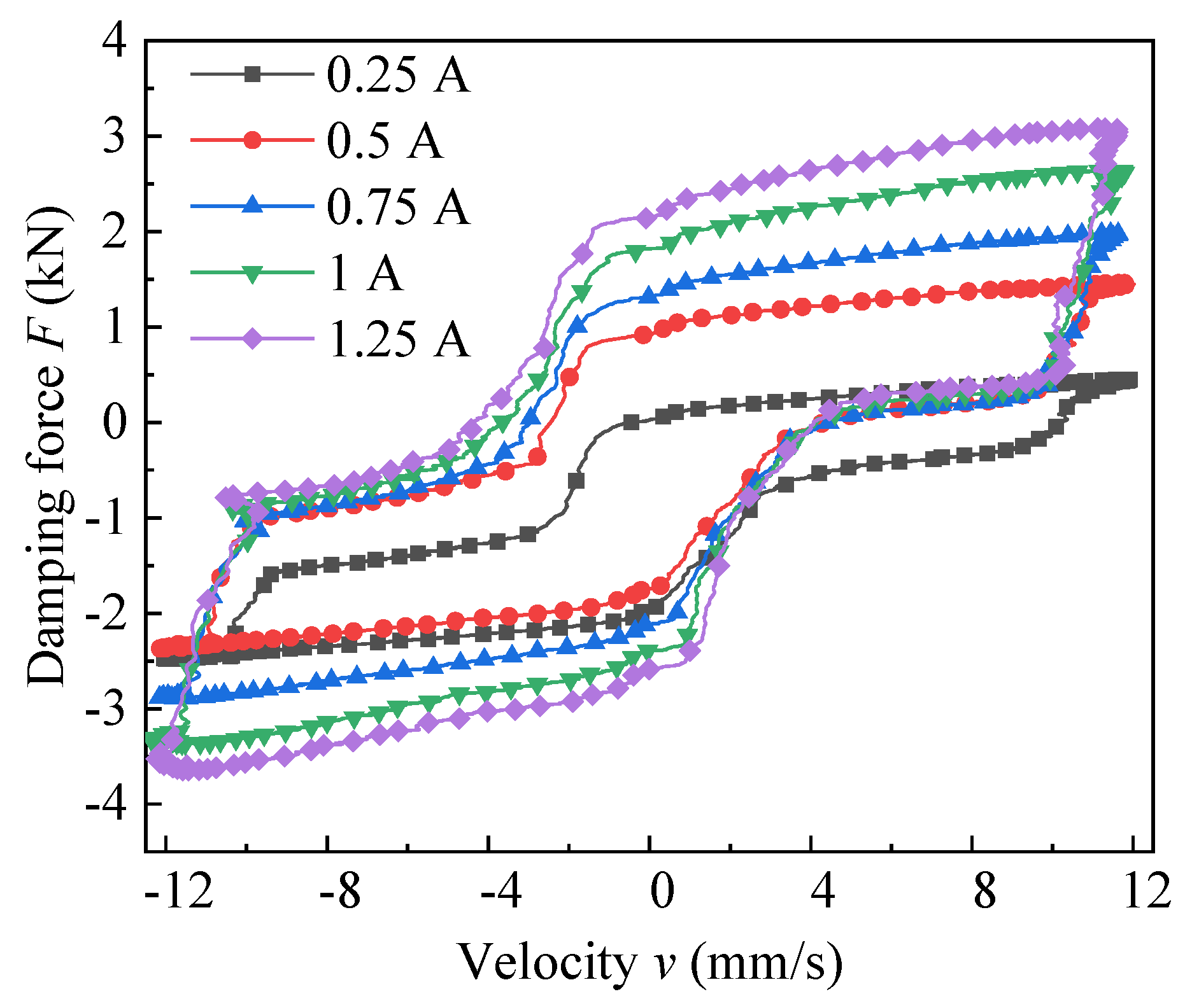
In the experiment, the power knob was manually adjusted to provide different loading current for the system, and then the required output damping force was obtained. By setting the displacement excitation with amplitude of 7.5 mm and frequency of 0.25 Hz, the damping force-displacement curves of the radial MR valve were obtained, as detailed in Figure 28. Observing Figure 28, the damping force augments with the increment of the applied current and the damping force-displacement curve was distributed inward and outward on the longitudinal axis. The experimental damping force appears a peak of 3.6 kN at the applied current of 1.25 A. Figure 29 shows the relation curve of damping force and velocity of the optimal radial MR valve under different current. Observing Figure 29, the damping force of the optimal radial MR valve increases with the increase of the current and piston velocity, the maximum damping force reaches about 3.6 kN at the applied current of 1.25 A. In addition, the upper left corner and lower right corner of the experimental curve were missing to a certain extent. The main reason was that the filling of MR fluid in the system was insufficient, which lead to the mixing of a certain volume of air in the system, and the absence of MR fluid in the hydraulic cylinder could not be compensated in time during the stretching and compression process.
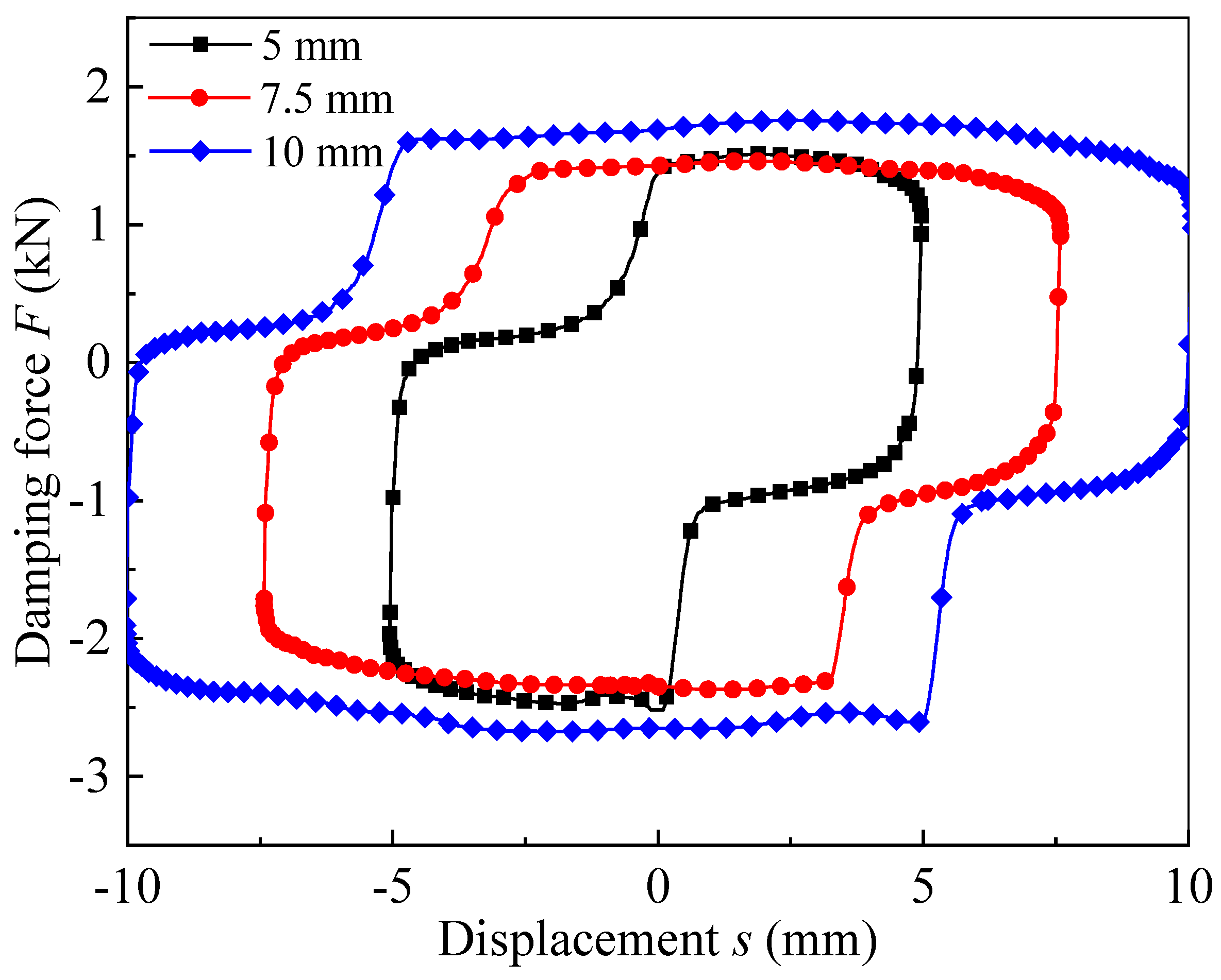
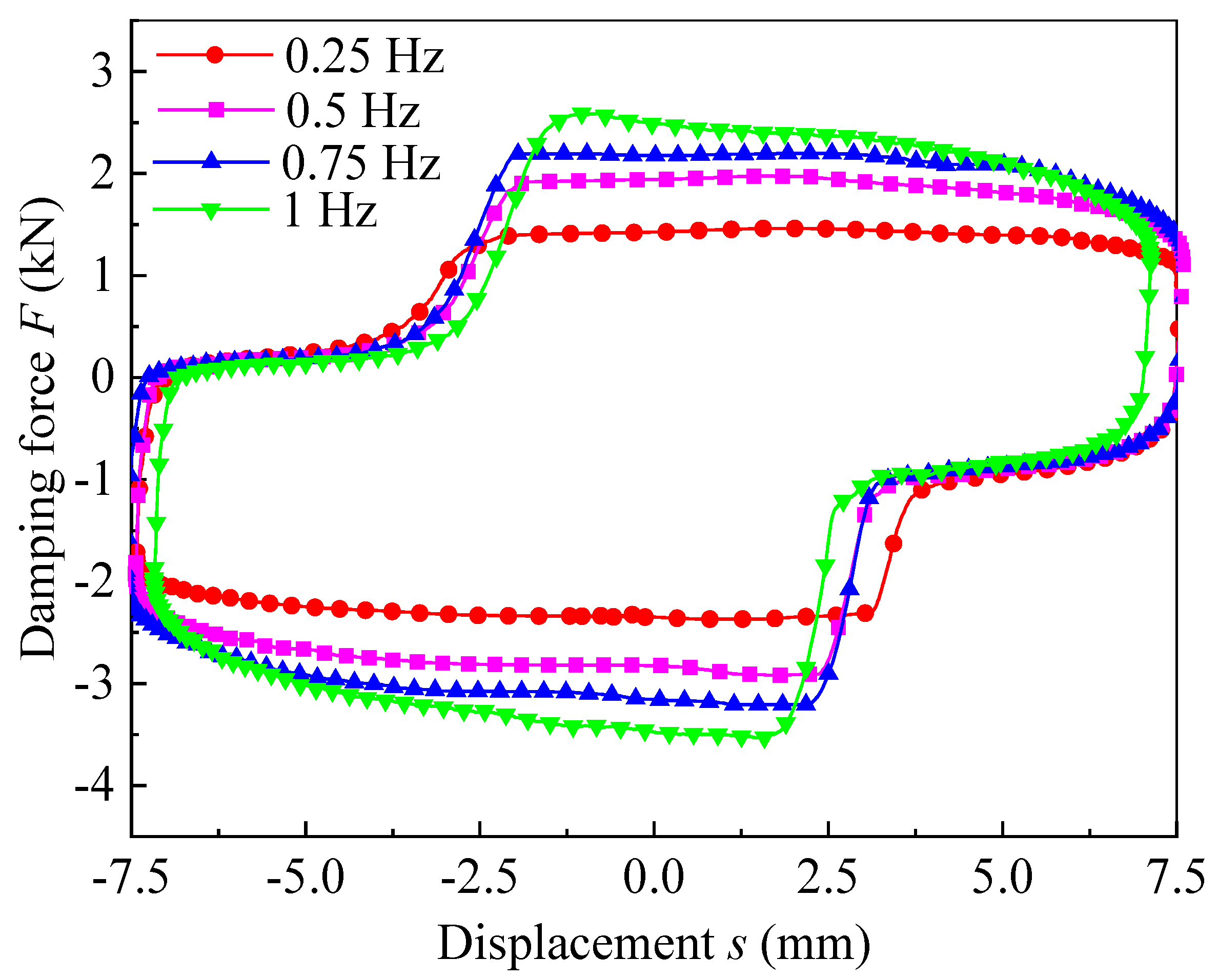
Figure 30 shows the damping force under different amplitudes at the frequency of 0.25 Hz and current of 0.5 A. It can be concluded that the damping force exhibits enhancement with the augmentation of the displacement amplitude. The reason is that the piston velocity increases with the increase of the displacement amplitude at a settled frequency. The maximum experimental damping force is 2.7 kN at amplitude of 10 mm. Figure 31 shows the damping force under different frequencies at the amplitude of 7.5 mm and current of 0.5 A. Due to the increase of frequency, the fluid flow rate in the system increases, which lead to the increasing of the viscous pressure drop, and the output damping force increases too. Moreover, the maximum damping force gently reaches 3.5 kN at the frequency of 1 Hz.

5.5.3. Comparison and Analysis of Dynamic Performance

The comparison of output damping force with initial and optimal radial MR valve is shown in Figure 32. In Figure 32a, when the current is fixed at 1 A, the amplitude is equal to 7.5 mm and the frequency is equal to 0.25 Hz, the maximum damping force of the initial radial MR valve is about 2.2 kN, while that of the optimal radial MR valve is about 3.4 kN. In Figure 32b, when the amplitude is fixed at 10 mm, the frequency is equal to 0.25 Hz and the current is equal to 0.5 A, the maximum damping force of the initial radial MR valve is about 1.8 kN, while that of the optimal radial MR valve is about 2.7 kN. In Figure 32c, when the frequency is fixed at 0.75 Hz, the amplitude is equal to 7.5 mm and the current is equal to 0.5 A, the maximum damping force of initial radial MR valve is about 2 kN, and that of optimal radial MR valve is about 3.2 kN. Therefore, under the same conditions, the damping force of the optimal valve controlled cylinder system was larger than that of the initial system.
Figure 33 shows the experimental pressure drop of initial and optimal valve. The pressure drop of the optimal valve is larger than that of the initial valve. When the excitation current is 1.8 A, the total pressure drop of the initial valve is 1.842 MPa, and the total pressure drop of the optimal valve is 2.58 MPa, and the increase is 40.07%. Therefore, the optimal radial MR valve has higher adjustable pressure drop range than the initial radial MR valve.
The above analysis shows that the pressure drop of the radial MR valve determines the output damping force of the radial MR valve controlled cylinder system. The greater the pressure drop produced by the MR valve, the greater the damping force of the bypass valve controlled cylinder system. he optimal valve controlled cylinder system was verified to achieve better damping performance. Therefore, the different output damping force can be satisfied by replacing the MR valve with a different pressure drop adjustable range.

6. Conclusions

A single coil radial MR valve with nonmagnetic sleeve in the middle of the coil winding frame is designed, which improves the magnetic circuit design reasonably. The modeling and simulation of the single coil radial MR valve are carried out. The simulation results show that the design of the initial structure and the setting of the basic parameters of the valve are reasonable.
By using the first-order and zero-order optimization tools in the ANSYS software, and according to the weight coefficients of λ1 = 0.75 and λ2 = 0.25, the multi-objective function is established. The results indicate the pressure drop of the optimal valve is obviously increased compared with that of initial valve. When the input current was 1 A, the pressure drop of the optimal radial MR valve could reach about 4 MPa, and the performance could be improved by nearly 2.7 times.
The average response time of the initial valve is about 90 ms, and that of the optimal valve is about 130 ms. As the key component of the MR valve bypass control damper, the damping force can be regulated to obtain good vibration reduction effect. The test results show that when the excitation current is 1.25 A, the maximum damping force of the optimal valve controlled cylinder system can reach about 3.6 kN.
By comparing and analyzing the damping force of the initial and optimal radial MR valve under the current, frequency and amplitude, it was found that the optimal valve had better damping performance. In addition, the pressure drop of the initial and optimal valve was also compared and analyzed, the experimental results show that the total pressure drop of the initial valve was 1.842 MPa, while the total pressure drop of the optimal valve was 2.58 MPa and the total pressure drop after optimization was increased by 40.07%; Therefore, the optimal radial MR valve had better damping performance.

Author Contributions

G.H. developed the radial MR valve and revised the paper; F.Z. conducted experimental research and wrote the first draft. L.Y. conducted theoretical analysis and set up the performance test rig. All authors have read and agreed to the published version of the manuscript.

Funding

This research was funded by the National Natural Science Foundation of China, grant number 51765016.

Conflicts of Interest

The authors declare no conflict of interest.

References

  1. Heo, Y.H.; Choi, D.; Yun, I.; Kim, S. A tiny haptic knob based on magnetorheological fluids. Appl. Sci. 2020, 10, 5118. [Google Scholar] [CrossRef]
  2. Yang, J.; Sun, S.S.; Tian, T.F.; Li, W.H.; Du, H.P. Development of a novel multi-layer MRE isolator for suppression of building vibrations under seismic events. Mech. Syst. Signal Process. 2016, 70–71, 811–820. [Google Scholar] [CrossRef] [Green Version]
  3. Tian, T.F.; Nakano, M. Fabrication and characterisation of anisotropic magnetorheological elastomer with 45 degrees iron particle alignment at various silicone oil concentrations. J. Intell. Mater. Syst. Struct. 2017, 29, 151–159. [Google Scholar] [CrossRef]
  4. Zhang, Y.; Li, D.; Cui, H.; Yang, J. A new modified model for the rheological properties of magnetorheological fluids based on different magnetic field. J. Magn. Magn. Mater. 2020, 500, 166377. [Google Scholar] [CrossRef]
  5. Hu, G.L.; Zhong, F.; Zhang, H.Y.; Ding, R.Q. Structure optimization and performance analysis of a multiple radial magnetorheological valve. J. Beijing Inst. Technol. 2017, 26, 458–467. [Google Scholar]
  6. Hu, G.L.; Zhang, J.W.; Liao, M.K.; Ding, R.Q. The effect of radial resistance gap on the pressure drop of a compact annular-radial-orifice flow magnetorheological valve. J. Beijing Inst. Technol. 2018, 27, 535–546. [Google Scholar]
  7. Ichwan, B.; Mazlan, S.A.; Imaduddin, F. Development of a modular MR valve using meandering flow path structure. Smart Mater. Struct. 2016, 25, 037001. [Google Scholar] [CrossRef]
  8. Hu, G.L.; Wu, L.F.; Li, L.S.; Yu, L.F. Performance Analysis of Rotary Magnetorheological Brake with Multiple Fluid Flow Channels. IEEE Access 2020, 8, 173323–173335. [Google Scholar] [CrossRef]
  9. Li, W.H.; Du, H. Design and experimental evaluation of a magnetorheological brake. Int. J. Adv. Manuf. Technol. 2003, 21, 508–515. [Google Scholar] [CrossRef]
  10. Bai, X.X.; Wereley, N.M.; Choi, Y.T. Magnetorheological energy absorber with dual concentric annular valves. J. Intell. Mater. Systerns Struct. 2016, 27, 944–958. [Google Scholar] [CrossRef]
  11. Tae-Hoon, L.; Chulhee, H.; Seung-Bok, C. Design and damping force characterization of a new magnetorheological damper activated by permanent magnet flux dispersion. Smart Mater. Struct. 2017, 27, 015013. [Google Scholar]
  12. Bai, X.X.; Cai, F.; Chen, P. Resistor-capacitor (RC) operator-based hysteresis model for magnetorheological (MR) dampers. Mech. Syst. Signal Pr. 2019, 117, 157–169. [Google Scholar] [CrossRef]
  13. Weber, F.; Distl, H.; Fischer, S.; Braun, C. MR Damper Controlled Vibration Absorber for Enhanced Mitigation of Harmonic Vibrations. Actuators 2016, 5, 27. [Google Scholar] [CrossRef]
  14. Sun, S.S.; Ning, D.H.; Yang, J. Development of an MR seat suspension with self-powered generation capability. J. Smart Mater. Struct. 2017, 26, 085025. [Google Scholar] [CrossRef]
  15. Yang, S.Y.; Han, C.; Shin, S.U.; Choi, S.B. Design and Evaluation of a Semi-Active Magneto-rheological Mount for a Wheel Loader Cabin. Actuators 2017, 6, 16. [Google Scholar] [CrossRef] [Green Version]
  16. Hu, G.L.; Long, M.; Huang, M.; Li, W.H. Design, Analysis, Prototyping, and Experimental Evaluation of an Efficient Double Coil Magnetorheological Valve. Adv. Mech. Eng. 2014, 6, 403410. [Google Scholar] [CrossRef] [Green Version]
  17. Ai, H.X.; Wang, D.H.; Liao, W.H. Design and Modeling of a Magnetorheological Valve with both Annular and Radial Flow Paths. J. Intell. Mater. Syst. Struct. 2006, 17, 328–334. [Google Scholar] [CrossRef]
  18. Hu, G.L.; Long, M.; Yu, L.F.; Li, W.H. Design and performance evaluation of a novel magnetorheological valve with a tunable resistance gap. Smart Mater. Struct. 2014, 23, 127001. [Google Scholar] [CrossRef]
  19. Hu, G.L.; Liao, M.K.; Li, W.H. Analysis of a compact annular-radial-orifice flow magnetorheological valve and evaluation of its performance. J. Intell. Mater. Syst. Struct. 2017, 28, 1322–1333. [Google Scholar] [CrossRef] [Green Version]
  20. Abd Fatah, A.Y.; Mazlan, S.A.; Koga, T.; Zamzuri, H.; Imaduddin, F. Design of magnetorheological valve using serpentine flux path method. Int. J. Appl. Electromagn. Mech. 2016, 50, 29–44. [Google Scholar] [CrossRef]
  21. Imaduddin, F.; Mazlan, S.A.; Zamzuri, H.; Yazid, I.I.M. Design and performance analysis of a compact magnetorheological valve with multiple annular and radial gaps. J. Intell. Mater. Syst. Struct. 2015, 26, 1038–1049. [Google Scholar] [CrossRef]
  22. Manjeet, K.; Sujatha, C. Magnetorheological valves based on Herschel–Bulkley fluid model: Modelling, magnetostatic analysis and geometric optimization. Smart Mater. Struct. 2019, 28, 115008. [Google Scholar] [CrossRef]
  23. Manjeet, K.; Sujatha, C. Chandramohan Geometric optimisation of magnetorheological valve using feedforward neural networks for distribution of magnetic flux density inside the valve. Smart Mater. Struct. 2019, 28, 105018. [Google Scholar]
  24. Xiong, S.P.; Wilfong, G.; Lumkes, J. Development of a novel high-speed actuation mechanism using a magneto-rheological fluid clutch and its application to a fluid control valve. J. Intell. Mater. Syst. Struct. 2019, 30, 2502–2516. [Google Scholar] [CrossRef]
  25. Seid, S.; Chandramohan, S.; Sujatha, S. Optimal design of an MR damper valve for prosthetic knee application. J. Mech. Sci. Technol. 2018, 32, 2959–2965. [Google Scholar] [CrossRef]
  26. Nguyen, Q.H.; Han, Y.M.; Choi, S.B.; Wereley, N.M. Geometry optimization of MR valves constrained in a specific volume using the finite element method. Smart Mater. Struct. 2007, 16, 2242–2252. [Google Scholar] [CrossRef]
  27. Shin, S.U.; Lee, T.H.; Cha, S.W. Optimal design and experimental analysis of a magnetorheological valve system for the vehicle lifter used in maintenance. J. Spie Smart Struct. Mater. Nondestruct. Eval. Health Monit. 2017, 10164, 101642C. [Google Scholar]
  28. Idris, M.H.; Imaduddin, F.; Mazlan, S.A.; Choi, S.B. A Concentric Design of a Bypass Magnetorheological Fluid Damper with a Serpentine Flux Valve. Actuators 2020, 9, 16. [Google Scholar] [CrossRef] [Green Version]
  29. Ntella, S.L.; Duong, M.T.; Civet, Y.; Pataky, Z.; Perriard, Y. Design Optimization of Miniature Magnetorheological Valves with Self-Sensing Capabilities Used for a Wearable Medical Application. In Proceedings of the 2020 IEEE/ASME International Conference on Advanced Intelligent Mechatronics (AIM), Boston, MA, USA, 6–9 July 2020; pp. 409–414. [Google Scholar]
  30. Hu, G.L.; Zhang, J.W.; Zhong, F.; Yu, L.F. Performance evaluation of an improved radial magnetorheological valve and its application in the valve controlled cylinder system. Smart Mater. Struct. 2019, 28, 047003. [Google Scholar] [CrossRef]
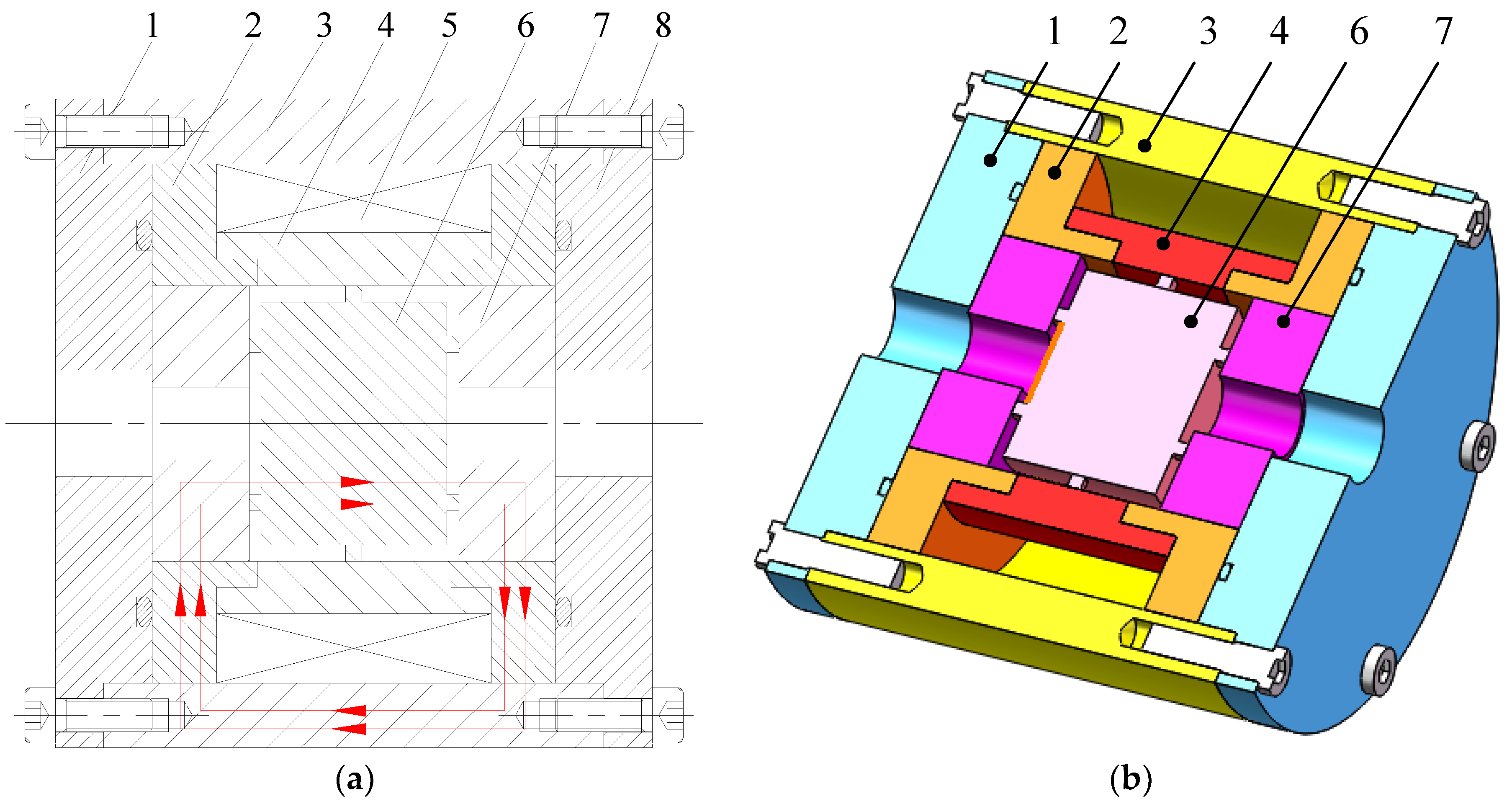
Figure 1. Structure diagram of radial MR valve with single excitation coil. (a) Schematic diagram; (b) 3D diagram. 1-Left end cover; 2-Magnetic disk; 3-Valve body; 4-Nonmagnetic sleeve; 5-Excitation coil; 6-Valve spool; 7-Positioning plate; 8-Right end cover.
Actuators 10 00034 g001
Figure 2. Magnetic circuit of radial MR valve.
Actuators 10 00034 g002
Figure 3. Equivalent magnetic circuit of radial MR valve: (a) control sections, (b) equivalent circuit.
Actuators 10 00034 g003
Figure 4. Schematic configuration of the distribution of pressure drop.
Actuators 10 00034 g004
Figure 5. τ–B curve of MR fluid.
Actuators 10 00034 g005
Figure 6. B-H curve of 10# steel.
Actuators 10 00034 g006
Figure 7. Geometry model of radial MR valve.
Actuators 10 00034 g007
Figure 8. Finite element model of radial MR valve.
Actuators 10 00034 g008
Figure 9. Distribution of magnetic flux lines.
Actuators 10 00034 g009
Figure 10. Contour of magnetic flux density.
Actuators 10 00034 g010
Figure 11. Distribution of magnetic flux density in disk damping gap.
Actuators 10 00034 g011
Figure 12. Magnetic flux density and pressure drop at different current.
Actuators 10 00034 g012
Figure 13. Magnetic flux density and adjustable coefficient under different disk damping gap.
Actuators 10 00034 g013
Figure 14. Magnetic flux density and adjustable coefficient under different thickness of positioning plate.
Actuators 10 00034 g014
Figure 15. Magnetic flux density and adjustable coefficient under different inner diameter of positioning plate.
Actuators 10 00034 g015
Figure 16. Optimization process.
Actuators 10 00034 g016
Figure 17. Optimization result of proposed radial MR valve: (a) Design variables, (b) objective function and state variables, and (c) pressure drop and adjustable coefficient.
Actuators 10 00034 g017aActuators 10 00034 g017b
Figure 18. Average magnetic flux density with current for the initial and optimal radial MR valve.
Actuators 10 00034 g018
Figure 19. Pressure drop varies with current for the initial and optimal radial MR valve.
Actuators 10 00034 g019
Figure 20. Prototypes of the proposed radial MR valve: (a) Components, and (b) Prototypes.
Actuators 10 00034 g020aActuators 10 00034 g020b
Figure 21. Experimental test system of the radial MR valve. 1-MR fluid tank; 2-Gear pump; 3-Relief valve I; 4-Relief valve II; 5-Pressure sensor I; 6-MR valve; 7-Pressure sensor II; 8-Computer; 9-Acquisition card; 10-Power supply I; 11-Power supply II.
Actuators 10 00034 g021
Figure 22. Experimental pressure of the optimal radial MR valve under different currents.
Actuators 10 00034 g022
Figure 23. Experimental pressure drop of the optimal radial MR valve under different loads.
Actuators 10 00034 g023
Figure 24. Step response diagram of the initial radial MR valve.
Actuators 10 00034 g024
Figure 25. Step response diagram of the optimal radial MR valve.
Actuators 10 00034 g025
Figure 26. Prototype of the optimal radial MR valve controlled cylinder system.
Actuators 10 00034 g026
Figure 27. Experimental test rig of the optimal radial MR valve controlled cylinder system.
Actuators 10 00034 g027
Figure 28. Damping force under different displacements.
Actuators 10 00034 g028
Figure 29. Damping force under different velocities.
Actuators 10 00034 g029
Figure 30. Variation of damping force relative to displacement under different amplitudes.
Actuators 10 00034 g030
Figure 31. Variation of damping force relative to displacement under different frequencies.
Actuators 10 00034 g031
Figure 32. Comparison of damping force of initial and optimal MR valve control cylinder system: (a) applied current of 1 A, (b) amplitude of 10 mm, and (c) frequency of 0.75 Hz.
Actuators 10 00034 g032
Figure 33. Pressure drop of initial and optimal radial flow MR valve controlled cylinder systems.
Actuators 10 00034 g033
Table 1. Performance of the initial and optimal radial MR valve.
ProjectInitial ValveOptimal Valve
λ1 = 1 and λ2 = 0λ1 = 0 and λ2 = 1λ1 = 0.75 and λ2 = 0.25
Objective function f1.000.397890.567210.68546
Adjustable coefficient K20.7112.1036.5116.77
Field-dependent pressure drop
pτ/MPa
1.90914.79811.51453.8007
Viscous pressure drop pη/MPa0.09220.03970.04140.2267
Magnetic flux density B ¯ /T0.48920.52620.47830.5182
Table 2. Weight and sizes of the initial and optimal radial MR valve.
ProjectInitial ValveOptimal Valve
λ1 = 1 and λ2 = 0λ1 = 0 and λ2 = 1λ1 = 0.75 and λ2 = 0.25
Radial damping gap g/mm1.51.002321.1323
Positioning plate thickness a/mm1213.9501616
Damping gap radius of circular tube R0/mm4.534.88894.1819
Valve spool radius R1/mm152016.17219.550
Thickness of valve body Dh/mm8666
Width of winding grooves T/mm34404040
Weight of valve G/kg2.41--2.22
Table 3. Step response time of the initial and optimal MR valve.
Current (A)Rising Response Time (ms)Falling Response Time (ms)
Initial DesignOptimal DesignInitial DesignOptimal Design
0.67112996144
1.2801396690
1.811916684107
Publisher’s Note: MDPI stays neutral with regard to jurisdictional claims in published maps and institutional affiliations.