Abstract
The magnetic circuit of existing linear force motors does not consider the issue of energy utilization of permanent magnets, and the structure is complicated. To achieve high energy utilization and simplify the structure, this paper presents a novel magnetic circuit topology for the linear force motors of electro-hydraulic servo-proportional valves. In order to rapidly and accurately calculate the static characteristics of the force motor, an analytical model is established by using the equivalent magnetic circuit method. The model comprehensively considers the magnetic leakage effect, edge effect, and permeability nonlinearity. A prototype of the force motor is designed and manufactured, and a special experimental platform is built. The prototype force motor has a linear force-displacement characteristic and the output force increases with the increase of the excitation currents, which can reach about 41 N at 2 A. This indicates that it is suitable as an electro-mechanical converter for electro-hydraulic servo-proportional valves. Moreover, the analytical model is used to perform parameter optimization and calculate the magnetic flux density in the working air gap and the force-displacement characteristics under different excitation currents. The results are in good agreement with the electromagnetic field finite element simulation and experimental results. They indicate that the analytical model can rapidly and accurately predict the static characteristics of the force motor. The research work provides good reference means for the design of magnetic circuit topology with consideration of the high energy utilization of permanent magnets, and also the accurate analytical modeling of valve electro-mechanical converters.
1. Introduction
Since its advent, electro-hydraulic control technology has occupied a high-end position in electro-mechanical transmission and control technology with its high power-density, large output force, and excellent static and dynamic characteristics. Therefore, it is widely used in aerospace technology, mining machinery, large power stations, steel and material testing machines, and other key applications [1,2,3]. As the core control components, the electro-hydraulic servo valve and proportional valve play a decisive role in the performance of the entire system [4,5]. The servo valve has excellent static and dynamic characteristics since it was mainly invented for the aviation industry. However, it has shortcomings of high manufacturing cost, complicated structure, and pilot stage leakage [6,7]. The proportional valve features a simple structure, excellent anti-pollution ability, and low cost, but it has disadvantages of low dynamic response, large hysteresis, and is usually used for open-loop control [8,9]. In recent years, the servo-proportional valve has appeared [10,11]. This valve features a direct action mechanism actuated by a linear electro-mechanical converter (LEMC), and the spool position is a closed-loop controlled by the displacement sensor. The servo-proportional valve has performance similar to the servo valve, while inheriting the advantages of a simple structure and good stability of the proportional valve. Therefore, it is increasingly popular in the field of industrial servo control.
As the conversion interface between electrical and mechanical energy, the electro-mechanical converter (EMC) has an important influence on the characteristics of the servo and proportional valves. EMC can be further divided into LEMC and rotary EMC. LEMC mainly includes moving the coil motor, proportional solenoid, and linear force motor (LFM). The working principle of moving the coil motor is similar to that of the voice coil in a loudspeaker, where a moving coil is placed in the external magnetic field produced either by winding or a permanent magnet. When energized, the moving coil is subjected to the magnetic force proportional to the current. The moving coil motor features high linearity and a large stroke and has excellent dynamic characteristics under large currents. However, a high current will cause serious heating, which usually requires additional cooling measures. For example, the Hitachi moving coil servo valve adopts a high current to ensure its dynamic characteristics, while compressed air is required to forcibly dissipate heat [12,13,14]. The proportional solenoid is widely used as an EMC for electro-hydraulic proportional valves. Figure 1a gives its magnetic circuit topology. To realize proportional control, the magnetic circuit of the proportional solenoid is deliberately divided into axial and radial components using a magnetic isolation ring, and then re-superposed to obtain the flat force-displacement characteristics. The proportional solenoid features a large thrust force and is easy to design as a “wet type” LEMC with high-pressure oil-resistant ability. However, it was originally developed from the solenoid electromagnet. Thus, it has a similar structure to the cylindrical shape armature, which results in large inertia of the armature component and thus a slower dynamic response. Since the welding of the magnetic isolation ring is cumbersome and quality issues such as air holes are prone to occur, people have also explored magnetic circuit topology without the magnetic isolation ring [15,16]. With the increasing demand for energy conservation, people have put forward higher requirements for the EMC’s efficiency [17,18]. The magnetic circuit of pure electric excitation has disadvantages of high power consumption and prominent coil heating problems, which seriously affect the service life. Introducing a permanent magnet to decrease the excitation level of the control coil and therefore reduce heat generation and power consumption has become mainstream for the design of modern electro-mechanical converters. Moog’s LFM is a typical representative in this regard. Figure 1b illustrates its magnetic circuit topology. Compared with the proportional solenoid, the configuration of the LFM features a single coil and double permanent magnet to constitute a differential magnetic circuit, which not only has large thrust force and fast dynamic response, but also reduces the control current and coil heating [19]. Therefore, the LFM has been successfully used as the EMC of Moog’s D633/634 series servo-proportional valves. Moreover, people have also investigated the novel magnetic circuit topology of the LFM. Two typical configurations are Li’s LFM [20] and Ding’s LFM [21], as shown in Figure 1c,d, respectively. The former inherits the topology of Moog’s LFM. By reducing the length of the axial non-working air gap and introducing the extra radial air gap, its power consumption can be reduced by 36%. The latter is more similar to a bi-directional proportional solenoid structure, which is characterized by a single permanent magnet and double-coil winding. However, these LFM configurations have common shortcomings: firstly, their structure is too complicated, with the yoke being composed of multiple parts; secondly, the existence of radial working air gaps greatly increases the coaxiality between armature and yoke components, which improves the manufacturing cost.
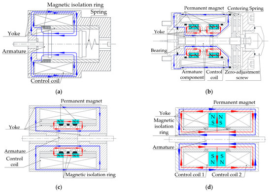
Figure 1.
Four different magnetic circuit topologies. (a) The proportional solenoid; (b) Moog’s LFM; (c) Li’s LFM; (d) Ding’s LFM.
In addition to electro-mechanical converters based on electromagnetic principles, some novel valves utilize modern functional materials, such as piezoelectric crystals [22], giant magnetostrictive material [23], magnetorheological fluid, and shape memory alloy as LEMC [24,25], which usually feature a very fast dynamic response of several kHz. However, the properties of these materials are greatly affected by temperature variation and nonlinear hysteresis. Also, it is usually necessary to design a mechanical amplification mechanism to compensate for the disadvantages of the small working stroke, which increases the whole weight and volume.
Rare-earth permanent magnets are non-renewable strategic resources [26,27], and some permanent magnets such as samarium cobalt permanent magnets are relatively expensive. Therefore, they possess important economic implications for improving the energy utilization of permanent magnets, especially for large-scale applications like valve electro-mechanical converters. Figure 2 shows the schematic diagram of the magnetic potential contribution to the external magnetic circuit of permanent magnets. Curves 1, 2, and 3 are the demagnetization curves of permanent magnet A, permanent magnet B, and permanent magnet C, respectively, and curve 4 is the load curve of the external magnetic circuit; lm1 is the length of permanent magnet B and permanent magnet C in the magnetizing direction; lm2 is the length of permanent magnet A in the magnetizing direction; Am1 is the cross-section area of permanent magnet A and permanent magnet B; Am2 is the cross-section area of permanent magnet C; Mc1 is the magnetic potential of permanent magnet B and permanent magnet C; Mc2 is the magnetic potential of permanent magnet A. Although the length of permanent magnet A along the magnetization direction is twice as long as that of permanent magnet B, the magnetic potential contributed to the external magnetic circuit only increases by ∆M1. In addition, the cross-section area of permanent magnet C is twice as much as permanent magnet B, and the magnetic potential contributed to the external magnetic circuit increases by ∆M2. Obviously, ∆M2 is greater than ∆M1. This is because, when the length of the permanent magnet in the magnetizing direction increases, not only does the magnetic potential provided to the external magnetic circuit increase, but also the magnetic reluctance increases proportionally; when the cross-section area of the permanent magnet increases, although the magnetic potential provided to the external magnetic circuit does not change, the magnetic resistance decreases significantly. In addition, modern electro-mechanical converters generally work with very small air gaps, which brings about a steep slope of the load curve, as shown in Figure 2. This indicates that, in order to improve magnetic energy utilization and save materials, the permanent magnet should be designed as a flat shape with a larger cross-section area, where the dimension in the magnetizing direction shall be as small as possible.
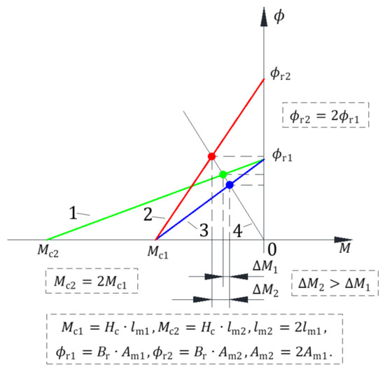
Figure 2.
The magnetic potential contribution to the external magnetic circuit of permanent magnets.
However, for the existing magnetic circuit topology of LFMs, the issue of the energy utilization of permanent magnets was not properly considered. For Moog’s LFM and Li’s LFM (Figure 1b,c), the permanent magnets are both designed as axial magnetized ring-shaped structures. Thus, the outer and inner diameters of such permanent ring magnets are limited by both the cylindrical armature and excitation winding. For a fixed volume, this would result in a small radius difference between the inner and outer ring, and therefore large axial dimensions (magnetizing direction). This would result in low magnetic energy utilization. For Ding’s LFM, it is impossible to further reduce the dimension of the permanent magnet in the magnetizing direction; otherwise, there will be no space for the control coils.
To achieve high energy utilization and also simplify the structure, this paper presents a novel magnetic circuit topology for the LPM of electro-hydraulic servo-proportional valves, where the structural simplicity and energy utilization of the permanent magnet are properly considered together so that the magnetic potential contributed to the external magnetic circuit can be maximized as much as possible. The rest of this paper is organized as follows: in Section 2, the configuration and working principle of the novel linear force motor (NLFM) are introduced. In Section 3, an accurate analytical model of the NLFM is established by using the equivalent magnetic circuit method. The model comprehensively considers the magnetic leakage effect, edge effect, and permeability nonlinearity. In Section 4, finite element simulation is used to verify the working principle of the NLFM, and also to study the influence of crucial parameters on its performance. In Section 5, a prototype of the NLFM is designed and manufactured, and a special experimental platform is built to test its static characteristics. The experimental results are then compared with both the analytical results and FEM simulation. Besides, the main features of NLFM and several LFM configurations from the literature are compared and discussed. Finally, some conclusions of this work are drawn in Section 6.
2. Configuration and Working Principle
Figure 3 shows the structural configuration of the NLFM, which is composed of the yoke component and armature component. The yoke component is a holistic truss structure with an excitation coil wound around its middle beam. The armature component is composed of a permanent magnet and two claw-pole-shaped armatures. To improve energy utilization, the permanent magnet is designed as a flat rectangular structure where the magnetizing direction coincides with its height direction. Thus, the dimension in the magnetizing direction can be kept as small as possible. Each armature has two pole shoes. The permanent magnet is embedded between the upper and low armatures to form the armature component, where the four pole shoes are distributed at 90° diagonally apart. One end of the shaft is fixed between the permanent magnet and two armatures, and the other end is inserted into a linear bearing. The spring is used to convert the output force into linear displacement.
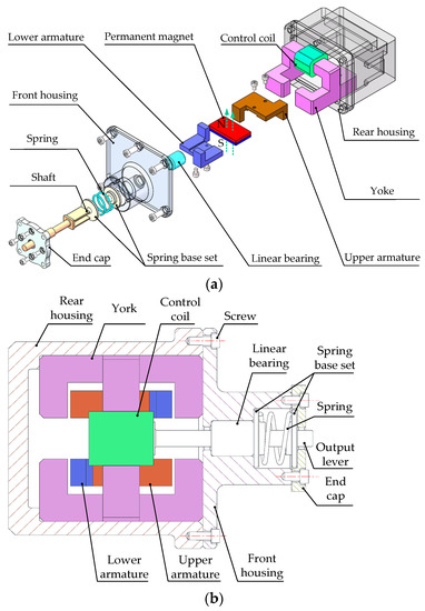
Figure 3.
The structural configuration of the NLFM. (a) A blow-up view of 3D parts; (b) the 2D section view.
Figure 4 shows the magnetic circuit topology of the NLFM, where the magnetizing direction of the permanent magnet is the positive direction of the Z axis. The permanent magnet magnetizes the upper and lower armatures as the N pole and S pole, respectively. Four working air gaps of the same length, , , and , are formed between the armature component and the yoke. When the control coil is de-energized, the armature is in the initial equilibrium position, and the lengths of the four air gaps are equal, as shown in Figure 4a. When the control coil is energized, the control flux generated by the coil and the polarized flux produced by the permanent magnet start to interact, where the magnetic flux of and is superposed and therefore enhanced, and the magnetic flux of and is neutralized and thus weakens. This causes the NLFM to generate a downward electromagnetic output force whose magnitude and direction can be adjusted by controlling the current, as shown in the Figure 4b.
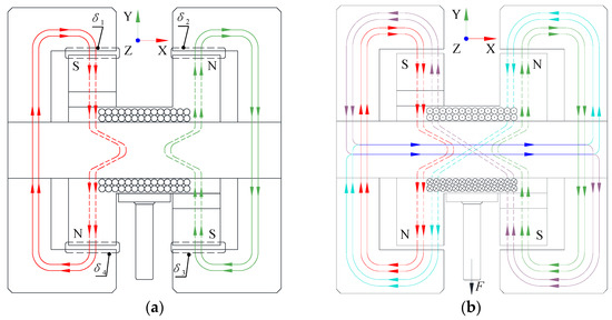
Figure 4.
The magnetic circuit topology of the NLFM. (a) de-energized; (b) energized.
3. Analytical Modeling of NLFM
3.1. Equivalent Magnetic Circuit Modeling
FEM simulation can accurately calculate the magnetic fields, but the whole process is computationally expensive. Varying the design parameters usually requires the model to be reconstructed. In this paper, in order to rapidly and accurately calculate the static characteristics of the NLFM, an analytical model is proposed by using the equivalent magnetic circuit method. The model comprehensively considers the magnetic leakage effect, edge effect, and permeability nonlinearity.
3.1.1. Modeling of Permanent Magnet
Figure 5 shows the schematic of the permanent magnet and its demagnetization curve, respectively, where is the flat surface area of the permanent magnet; is the length of the magnetization direction; the line is the demagnetization curve of permanent magnet; is the operating point on the permanent magnet demagnetization curve; the slope of the demagnetization curve represents the permeability ; is the coercive force; is the residual magnetic flux density. Figure 6 shows the equivalent magnetic circuit model of the permanent magnet, where is the internal magnetic reluctance of the permanent magnet; is the magnetic flux generated by the permanent magnet; is the magnetic potential generated by the permanent magnet; is the magnetic potential provided to the external magnetic circuit, namely the polarized magnetic potential.

Figure 5.
A schematic of the permanent magnet and its demagnetization curve. (a) The dimension and magnetizing direction; (b) the demagnetization curve.
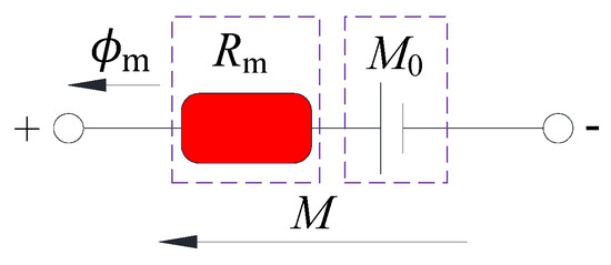
Figure 6.
The equivalent magnetic circuit model of the permanent magnet.
The permeability can be written as
where and are the magnetic flux density and the magnetic field intensity at point of , respectively.
From Equation (1), we have
The relationship between the and the can be written as
Combining Equations (2) and (3), the can be written as
According to Equation (4), the can be written as
Therefore, the can be written as
The can be written as
By combining Equations (5)–(7), we can have
Equation (8) shows that the magnetic potential generated by the permanent magnet can be divided into two parts: one is provided to the external magnetic circuit, and the other is consumed by the internal reluctance of the permanent magnet itself.
3.1.2. Analysis of Air Gap Reluctance
The reluctance of the working air gap has a crucial influence on the calculation accuracy of the entire magnetic field of NLFM. When the magnetic flux flows through the air gaps, it will diffuse. Such phenomena can be called edge effects. When the length of the air gap increases, the ratio of the diffused magnetic flux to the total air gap magnetic flux will also increase, and its influence cannot be ignored. According to the distribution of the air gap magnetic fields between the poles of yoke and armatures, the entire air gap magnetic field can be segmented into several magnetic flux tubes [28], as shown in Figure 7, where the Ra–Ri are reluctances of diffused flux tubes, and the Rx is the reluctance of main flux tubes. The reluctance of these flux tubes can be calculated by the relevant formulas listed in Table 1.
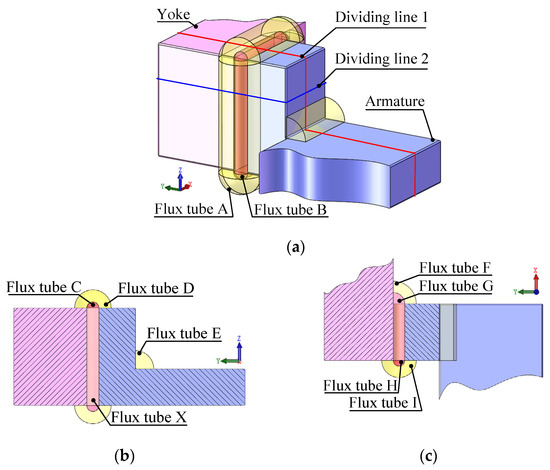
Figure 7.
A schematic of segmented magnetic flux tubes. (a) Flux tube A&B; (b) Flux tube C, D, E&X; (c) Flux tube F, G, H&I.

Table 1.
Reluctance calculation of segmented magnetic flux tubes [28].
Therefore, the reluctance of the air gap with consideration of the edge effect can be written as
where, the Ra–Ri are reluctances of diffused flux tubes and the Rx is the reluctance of main flux tubes, as shown in Table 1.
Furthermore, reluctance of the air gap without consideration of edge effect can be written as
By solving Equation (9), the reluctances , , and of the air gaps , , and can be obtained as shown in Figure 8, where the blue line shows the reluctance without consideration of the edge effect, and the red line illustrates the reluctance with consideration of the edge effect. The parameters used for the reluctance calculation are listed in Table 2. It can be seen that the result of the red line is much smaller than that of the blue line, which verifies the necessity for considering the edge effect in the magnetic circuit calculation.
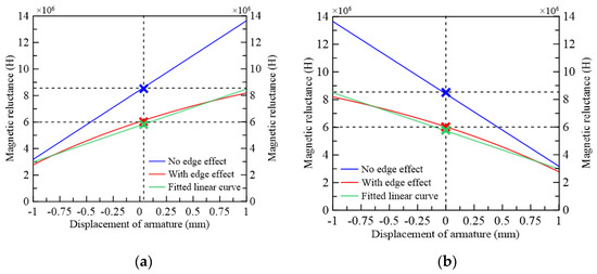
Figure 8.
The variation of air gap magnetic reluctance with armature displacement. (a) , . (b) , .

Table 2.
The parameters used for the calculation of reluctance.
From Figure 8, it can be seen that the variation of reluctance with the edge effect has a slight nonlinear relationship with the length of the air gap. For convenience, in the following analysis, they can be fitted into linear curve, as shown by the green line in Figure 8, where the maximum difference does not exceed 3%. Therefore, the fitted linear expression can be written as
where ; is the magnetic reluctance of the air gap when the armature is in the middle position, and .
3.1.3. Equivalent Magnetic Circuit Modeling
The leakage flux from the permanent magnet and control coil has a great influence on magnetic circuit analysis, which would lead to inaccuracy in quantitative analysis. In this paper, the concept of the utilization ratio of magnetic flux is introduced to the phenomenon of leakage flux. Figure 9 shows the equivalent magnetic circuit diagram of NLFM considering both the edge effect and the magnetic leakage. The leakage flux can be written as
where and are the utilization ratio of flux generated by the permanent magnet and the control coil, respectively; and are the leakage flux of the permanent magnet and the control coil, respectively.
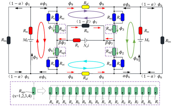
Figure 9.
The equivalent magnetic circuit diagram of NLFM.
The reluctances of the remaining magnetic circuit of NLFM can be expressed as
where is the length of the armature claw; is the length of the armature’s main plane; is the total length of the yoke; is the magnetic permeability of soft magnetic material of the armature and yoke; is the area of the magnetic pole face of the armature claw; is the contact area between the armature’s main plane and the permanent magnet; is the cross-sectional area of the armature along the vertical magnetic flux direction.
In the equivalent magnetic circuit modeling, the magnetic reluctance of the armature, the yoke, and the air gap are similar to the resistance, the magnetic potential of the permanent magnet and the control coil is similar to the voltage, and the magnetic flux of each circuit is similar to the current. Therefore, using Kirchhoff’s Law of current and voltage, the equivalent magnetic circuit model of the NLFM can be solved, and the following equations can be obtained
where is the number of turns of control coil; is the excitation current; , , and can be further written as
3.2. Analysis of Nonlinear Permeability
Both the armature and the yoke of NLFM are made of soft magnetic material DT4, whose permeability will vary with the magnetic flux density B. This leads to a nonlinear relationship between B and H, as shown in Figure 10. Therefore, in order to obtain a high-accuracy analytical model, the nonlinearity of permeability must be taken into account. According to the B-H curve of DT4 and Equation (14), the non-linear value of is iteratively calculated, as shown in Figure 11.
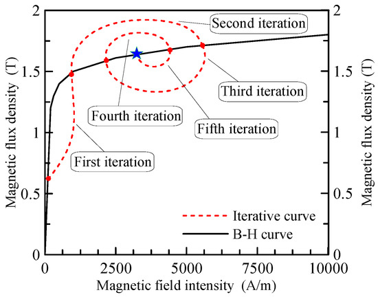
Figure 10.
The B-H curve of DT4 [29] (including iterative curve).

Figure 11.
The iterative steps for solving nonlinear magnetic circuit equations.
3.3. Electromagnetic Force Calculation
According to Equation (14) and the diagram of the equivalent magnetic circuit (Figure 9), it can be seen that when the coil is not energized, the armature is in the middle position, and the magnetic flux of the working air gap can be written as
Similarly, by only considering the magnetic field generated by the control coil, the corresponding magnetic flux of the working air gap can be obtained
Due to the symmetry of the magnetic circuit, we can have
According to Equations (15) and (19), the following equation can be written as
According to Equation (15), the polarized magnetic potential and the controlled magnetic potential of the NFLM can be written as
The total flux at the four air gaps can thus be obtained from Equations (15)–(20)
The constant in Equations (22) and (23) can be written as
The length of the working air gap g is very small, so the magnetic flux of the working air gap can be regarded as uniformly distributed. According to Maxwell’s equations, the total output force of NLFM can be written as
where and are the electromagnetic force generated by the air gap and , respectively.
Substituting Equations (23) and (24) into (26), we can have
where , and can be written as
Equations (1)–(27) constitute the full analytical model of NLFM, which will be used to perform parameter optimization, calculate force-displacement characteristics and magnetic flux densities in the following analysis.
4. Finite Element Simulation
Though computationally expensive, the finite element method can directly calculate the magnetic field accurately and provide an in-depth understanding of the magnetic field distribution. In this paper, it is employed to validate the analytical model of the NLFM. The FEM model of NLFM is established using electromagnetic-field finite-element software Ansoft Maxwell. Figure 12 shows the simulated magnetic field vector diagram of NLFM with a current of 1 A and armature displacement of 1.4 mm. When the control coil is energized, the control flux generated by the coil and the polarized flux produced by the permanent magnet begin to interact, where the magnetic flux of and is superposed and enhanced, and the magnetic flux of and is neutralized and thus weakens. Therefore, a downward electromagnetic force is generated. The results of the finite-element simulation are consistent with the working principle of Section 3. In addition, the diffusion phenomenon arises when the magnetic flux enters the air gap from the end face of the magnetic pole. Therefore, the edge effect must be taken into account in the calculation of the reluctance.
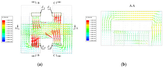
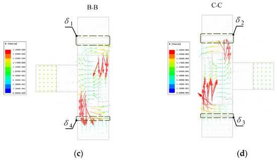
Figure 12.
The magnetic field vector diagram of NLFM. (a) vertical view. (b) A-A section view. (c) B-B section view. (d) C-C section view.
Figure 13 shows the simulated magnetic field cloud diagram with different excitation currents. It can be observed that when the current increases, magnetic saturation always occurs at the ends of the upper and lower armatures and the middle beam of the yoke, which indicates that the output force can be further improved by increasing the dimensions of these locations. The magnetic saturation level also changes when the current direction is reversed. In addition, when current increases, the magnetic flux density in the peripheral corner area of the yoke does not vary significantly, which shows that these areas could be removed to improve the power to weight ratio of the NLFM.

Figure 13.
The magnetic field cloud diagram of NLFM. (a) x = 0 mm, = −2 A. (b) x = 0 mm, = 0 A. (c) x = 0 mm, = 2 A.
Some key parameters have a significant influence on the performance of NLFM. In this paper, four parameters, namely, the width of rectangular pole shoe l, the length of working air gap g, the coil current I, and the width of permanent magnet lw, are selected to perform parametric design based on both analytical modeling and FEM simulation. It can be seen that the FEM simulated results are quite close to the analytical ones, which verifies the correctness of the analytical model. Varying l actually changes the effective area of the working air gap. Figure 14a shows the influence of l on force-displacement characteristics. The output force increases with the increase of l, which means l should be as large as possible. Figure 14b shows the influence of g on the force-displacement characteristics. Relatively speaking, reducing g is very effective since it can greatly increase the output force. However, the slope of the curve will become steeper, and the working stroke of the NLFM will be limited if g is too small. This indicates that the working stability needs to be considered and the choice of g needs to be compromised. Figure 14c shows the influence of i on force-displacement characteristics. The output force can be increased by properly increasing i. The force increased from 1 A to 1.5 A is greater than the counterpart increased from 1.5 A to 2 A, which indicates that the magnetic field of the NLFM is gradually saturated, and such a trend is demonstrated more clearly through the FEM simulation. Besides, a large current would also result in a heating dissipation problem. Figure 14d shows the influence of lw on force-displacement characteristics. An increase of lw will slightly increase the output force. However, this would also increase the size of the armature, which indicates that a proper compromise also needs to be made.
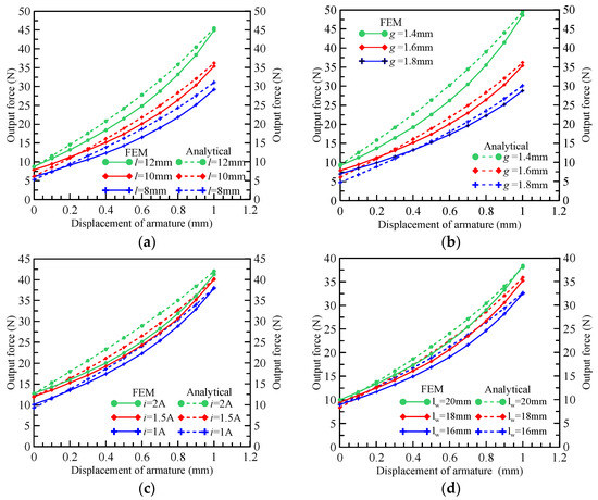
Figure 14.
The parametric design via both analytical modeling and FEM simulation. (a) The influence of l on force-displacement characteristics. (b) The influence of g on force-displacement characteristics. (c) The influence of i on force-displacement characteristics. (d) The influence of lw on force-displacement characteristics.
5. Experimental Study
Based on the analytical modelling and FEM simulation, the key structural parameters and material of NLFM are determined, as shown in Table 3, Table 4, Table 5 and Table 6. Then, a prototype of NLFM is designed and manufactured, as shown in Figure 15. A special experimental platform for static characteristics of NLFM is also designed and built, as shown in Figure 16. The experimental platform mainly consists of a signal amplifier, voltage source, linear micrometer, gauss probe, force sensor, and current source. The yoke of the prototype is fixed on a linear micrometer, whose measuring range is from –30 mm to 30 mm with an accuracy of 0.01 mm, and its output shaft is connected with the force sensor. By manually adjusting the linear micrometer, the yoke can move axially relative to the armature, and its displacement can be recorded. The output force can be measured by the force sensor. In this way, the force-displacement characteristics can be obtained. Besides, the gauss meter is used to measure the magnetic flux density by inserting its probe into the working air gap of the NLFM.

Table 3.
Key structural parameters of the NLFM prototype.

Table 4.
The materials used for the key structure.

Table 5.
Magnetic properties of DT4 [29].

Table 6.
Magnetic properties of NdFeB 35 [29].
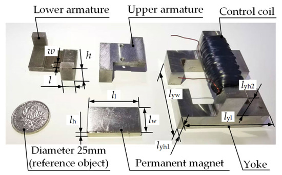
Figure 15.
The prototype of NLFM.
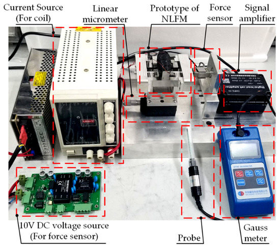
Figure 16.
The experimental platform for the prototype of the NLFM.
Figure 17 shows a comparison between analytical, FEM simulated and experimental results of the force-displacement characteristics of the NLFM. Table 7 summarize the maximum output forces. It can be seen that the curves show a monotonous upward trend with the increase of armature displacement. When i is 2 A, the maximum output force from analytical modeling, FEM simulation and experiment are 44.9 N, 41.3 N and 40.1 N, respectively. Figure 18 illustrates the comparison between analytical, FEM simulated and experimental results of the magnetic flux density of air gap and . Table 8 lists the magnetic flux densities of and when the armature displacement x = 0.8 mm. It can be found that the curves for B of show a linear downward trend with the increase of x, indicating the magnetic flux of superposes and therefore enhances. While the curves for B of show a linear upward trend with the increase of x, indicating the magnetic flux of neutralizes and thus weakens. When x = 0.8 mm, the B of from analytical modeling, FEM simulation and experiment are 0.412 T, 0.425 T and 0.402 T, respectively. And the B of are 0.120 T, 0.111 T and 0.132 T, respectively. The differential variation of B again validates the working principle of the NLFM discussed in Section 2. Besides, the analytical, FEM simulated and experimental results are in good agreement, which also verifies the accuracy of analytical model of the NLFM.
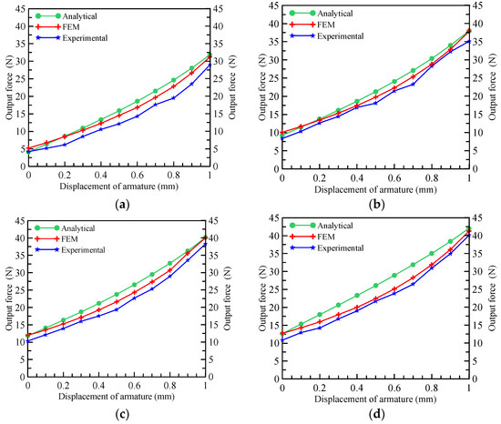
Figure 17.
Force-displacement characteristic curve. (a) 0.5 A. (b) 1 A. (c) 1.5 A. (d) 2 A.

Table 7.
Summary of the maximum output force.
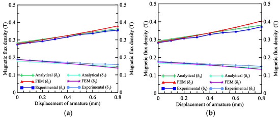
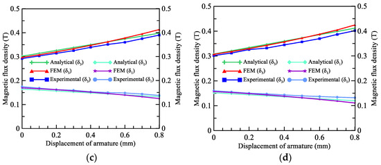
Figure 18.
Magnetic flux density curve. (a) 0.5 A. (b) 1 A. (c) 1.5 A. (d) 2 A.

Table 8.
Summary of the magnetic flux density of and (x = 0.8 mm).
Finally, an overall comparison between existing LFMs in the Figure 1 and the NLFM are performed, as shown in Table 9. For the working stroke range, all four configurations in the table are quite close. The output force of the NLFM is relatively small due to the magnetic saturation in the armature pole shoe, as shown in Figure 13. This also indicates that further structure optimization is needed in future research. With the proposed novel magnetic circuit topology, the NLFM features high magnetic energy utilization ratio over existing LFMs. Besides, the NLFM also has several advantages over the existing configurations. Firstly, since it only needs single permanent magnet and single control coil, the NLFM has features of simple structure and fewer parts, while the existing LFMs configuration needs either dual permanent magnets or dual control coils. Secondly, the yoke of the NLFM is a simple and integral truss structure, which is relatively easy to be machined and assembled. Thirdly, all existing LFMs have radial working air gap due to their cylindrical armature structure, and the existence of radial working air gaps increases the coaxiality between armature and yoke components, which improves the manufacturing and assembly cost. While for the NLFM, there is only an axial working air gap, which makes unnecessary to maintain high machining accuracy between yoke and armature components, thus greatly reducing the manufacturing and assembly cost.

Table 9.
Comparison between the NLFM and existing LFMs.
6. Conclusions
(1) In order to improve magnetic energy utilization and save materials, the permanent magnet of a valve electro-mechanical converter should be designed as a flat shape with a larger cross-section area, where the dimension in the magnetizing direction shall be as small as possible.
(2) A novel magnetic circuit topology for a linear force motor is proposed. To improve energy utilization, the permanent magnet is designed as a flat rectangular structure, where the magnetizing direction coincides with its height direction. Thus, the dimension in the magnetizing direction can be kept as small as possible. In addition, such configuration has advantages of a simple structure, few parts, and easy machining and assembly. Experimental results show that the prototype has linear force-displacement characteristics with a thrust force of 41 N at 2 A, which is suitable for the electro-mechanical converter for electro-hydraulic servo-proportional valves.
(3) An analytical model is established by using the equivalent magnetic circuit method. The model comprehensively considers magnetic leakage effect, edge effect, and permeability nonlinearity. The results are in good agreement with the FEM simulation and experimental results, which indicate that the analytical model can rapidly and accurately predict the static characteristics of the NLFM.
Author Contributions
Conceptualization, B.M.; methodology, H.X.; formal analysis, H.X.; investigation, B.M.; resources, B.M.; software, B.L. and M.D.; validation, C.Z.; data curation, B.L.; writing—original draft preparation, H.X.; writing—review and editing, B.M.; supervision, S.L. and B.M.; project administration, H.X.; funding acquisition, S.L. and B.M. All authors have read and agreed to the published version of the manuscript.
Funding
This research was funded by the National Natural Science Foundation of China, grant number 51975524, the National Key Research and Development Program of China, grant number 2019YFB2005200 and Open Funding of Key Laboratory of Special Purpose Equipment and Advanced Processing Technology, Ministry of Education and Zhejiang Province, Zhejiang University of Technology, grant number EM2020120105.
Institutional Review Board Statement
Not applicable.
Informed Consent Statement
Not applicable.
Data Availability Statement
Not applicable.
Conflicts of Interest
The authors declare no conflict of interest.
References
- Xu, B.; Shen, J.; Liu, S.; Su, Q.; Zhang, J. Research and Development of Electro-hydraulic Control Valves Oriented to Industry 4.0: A Review. Chin. J. Mech. Eng. 2020, 33, 1–20. [Google Scholar] [CrossRef]
- Du, H.; Liu, X.; Zhang, B.; Lin, Z. Efficiency of electro-hydraulic servo steering for heavy construction vehicles. Autom. Constr. 2020, 120, 103413. [Google Scholar] [CrossRef]
- Nahian, S.A.; Truong, D.Q.; Chowdhury, P.; Das, D.; Ahn, K.K. Modeling and fault tolerant control of an electro-hydraulic actuator. Int. J. Precis. Eng. Manuf. 2016, 17, 1285–1297. [Google Scholar] [CrossRef]
- Tamburrano, P.; Plummer, A.R.; Distaso, E.; Amirante, R. A review of electro-hydraulic servovalve research and development. Int. J. Fluid. Power. 2018, 19, 1–23. [Google Scholar] [CrossRef]
- Winkler, B. Recent advances in digital hydraulic components and applications. In Proceedings of the 9th Workshop on Digital Fluid Power, Aalborg, Denmark, 7 September 2017. [Google Scholar]
- Plummer, A. Additive Manufacture of Hydraulic Components. In Proceedings of the 9th International Conference on Fluid Power Transmission and Control, Hangzhou, China, 13 April 2017. [Google Scholar]
- Liu, X.; Shang, Y.; Jiao, Z.; Tang, H. Aircraft anti-skid braking control with flow servo-valve. In Proceedings of the 2015 International Conference on Fluid Power and Mechatronics (FPM), Harbin, China, 5 August 2015; pp. 536–541. [Google Scholar]
- Liu, W.; Wei, J.; Fang, J.; Li, S. Hydraulic-feedback proportional valve design for construction machinery. Proc. Inst. Mech. Eng. Part C J. Eng. Mech. Eng. Sci. 2015, 229, 3162–3178. [Google Scholar] [CrossRef]
- Zhang, J.; Lu, Z.; Xu, B.; Su, Q. Investigation on the dynamic characteristics and control accuracy of a novel proportional directional valve with independently controlled pilot stage. ISA Trans. 2019, 93, 218–230. [Google Scholar] [CrossRef] [PubMed]
- Wang, S.; Weng, Z.; Jin, B. A Performance Improvement Strategy for Solenoid Electromagnetic Actuator in Servo Proportional Valve. Appl. Sci. 2020, 10, 4352. [Google Scholar] [CrossRef]
- Fang, J.H.; Kong, X.W.; Zhu, X. The Modeling and Experimental Verification of a Servo-Proportional Valve. Appl. Mech. Mater. 2012, 220–223, 1018–1022. [Google Scholar] [CrossRef]
- Code, K. Voice Coil Actuator with Integrated LVDT. U.S. Patent US9395511B1, 19 July 2016. [Google Scholar]
- Ahn, D.; Kim, H.; Choi, K.; Choi, Y.M. Design process of square column-shaped voice coil motor design for magnetic levitation stage. Int. J. Appl. Electromagn. Mech. 2019, 62, 1–24. [Google Scholar] [CrossRef]
- Zhou, P.; Zhang, Y.; Dai, X. Research on Cooling Methods of Voice Coil Motor. In Proceedings of the 25th International Conference on Nuclear Engineering, Shanghai, China, 2 July 2017; p. 57793. [Google Scholar]
- Huang, L.; Ji, H.; Zhu, Y. Analysis of effective working characteristic of the proportional solenoid. In Proceedings of the 2017 International Conference on Green Energy and Applications (ICGEA), Singapore, 11 May 2017; pp. 35–38. [Google Scholar]
- Meng, B.; Lai, Y.J.; Qiu, X.G. Regulation Method for Torque–Angle Characteristics of Rotary Electric–Mechanical Converter Based on Hybrid Air Gap. Chin. J. Mech. Eng. 2020, 33, 1–11. [Google Scholar] [CrossRef]
- Bolyukh, V.F.; Luchuk, V.F.; Rassokha, M.A. High-efficiency impact electromechanical converter. Russ. Electr. Eng. 2011, 82, 104. [Google Scholar] [CrossRef]
- Yu, Q.; Bilgin, B.; Emadi, A. Loss and efficiency analysis of switched reluctance machines using a new calculation method. IEEE Trans. Ind. Electron. 2015, 62, 3072–3080. [Google Scholar] [CrossRef]
- Direct Drive Servo Valves D633/D634. Available online: https://www.heash-tech.com/uploads/59ba1fb5e65b8717954917.pdf (accessed on 28 January 2021).
- Li, Y.; Ding, F.; Cui, J. Low power linear actuator for direct drive electrohydraulic valves. J. Zhejiang Univ. Sci. A 2008, 9, 940–943. [Google Scholar] [CrossRef]
- Li, Q.P.; Ding, F.; Wang, C.L. Novel bidirectional linear actuator for electrohydraulic valves. IEEE Trans. Magn. 2005, 41, 2199–2201. [Google Scholar]
- Han, C.; Choi, S.B.; Han, Y.M. A piezoelectric actuator-based direct-drive valve for fast motion control at high operating temperatures. Appl. Sci. 2018, 8, 1806. [Google Scholar] [CrossRef]
- Yang, Z.S.; He, Z.B.; Yang, F.B. Design and analysis of a voltage driving method for electro-hydraulic servo valve based on giant magnetostrictive actuator. Int. J. Appl. Electromagn. Mech. 2018, 57, 1–18. [Google Scholar] [CrossRef]
- Rao, A.; Srinivasa, A.R.; Reddy, J.N. Design of Shape Memory Alloy (SMA) Actuators; Springer: Berlin, Germany, 2015. [Google Scholar]
- Shi, H.; He, B.; Wang, Z. Magneto-mechanical behavior of magnetic shape memory alloy and its application in hydraulic valve actuator. Chin. J. Mech. Eng. 2018, 54, 235–244. [Google Scholar] [CrossRef]
- Nakamura, H. The current and future status of rare earth permanent magnets. Scr. Mater. 2018, 154, 273–276. [Google Scholar] [CrossRef]
- Coey, J.M.D. Perspective and prospects for rare earth permanent magnets. Engineering 2020, 6, 119–131. [Google Scholar] [CrossRef]
- Wang, B.L. Electromagnetic Electrical Design; National Defend Industry Press: Beijing, China, 1988; ISBN 9787118005691. [Google Scholar]
- Zhou, X.Z. Electrician Technology Handbook; Beijing Chinese Electric Power Publish Company: Beijing, China, 2004; ISBN1 7508319702. ISBN2 9787508319704. [Google Scholar]
Publisher’s Note: MDPI stays neutral with regard to jurisdictional claims in published maps and institutional affiliations. |
© 2021 by the authors. Licensee MDPI, Basel, Switzerland. This article is an open access article distributed under the terms and conditions of the Creative Commons Attribution (CC BY) license (http://creativecommons.org/licenses/by/4.0/).


