Review

Applications of Magnetorheological Fluid Actuator to Multi-DOF Systems: State-of-the-Art from 2015 to 2021

1
Department of Future Convergence Engineering, Kongju National University, Cheonan 31080, Korea
2
Department of Future Automotive Engineering, Kongju National University, Cheonan 31080, Korea
3
Department of Mechanical Design Engineering, Kumoh National Institute of Technology, Daehak-ro 61, Gumi 39177, Korea
4
Department of Mechanical Engineering, The State University of New York, Korea (SUNY Korea), Incheon 21985, Korea
5
Department of Mechanical Engineering, Industrial University of Ho Chi Minh City (IUH), 12 Nguyen Van Bao Street, Vap District, Ho Chi Minh City 70000, Vietnam
*
Authors to whom correspondence should be addressed.
Actuators 2022, 11(2), 44; https://doi.org/10.3390/act11020044
Submission received: 29 December 2021 / Revised: 27 January 2022 / Accepted: 29 January 2022 / Published: 1 February 2022
(This article belongs to the Special Issue Design and Application of Actuators with Multi-DOF Movement)

Abstract

:
This review article presents various multi-DOF application systems that utilize smart magnetorheological (MR) fluid. It is well known that MR fluid has been actively studied and applied in many practical systems such as vehicle suspension dampers. The design requirements for the effective applications of MR fluid include geometry optimization, working principles, and control schemes. The geometry optimization is mostly related to the size minimization with high damping force, while the working principles are classified into the shear mode, the flow mode, and the squeeze mode depending on the dominant dynamic motion of the application system. The control schemes are crucial to achieve final targets such as robust vibration control against disturbances. It should be addressed that advanced output performances of MR application systems heavily depends on these three requirements. This review article presents numerous application systems such as sandwich structures, dampers, mounts, brakes, and clutches, which have been developed considering the three design requirements. In addition, in this article some merits and demerits of each application system are discussed to enable potential researchers to develop more effective and practical MR application systems featuring the multi-DOF dynamic motions.

1. Introduction

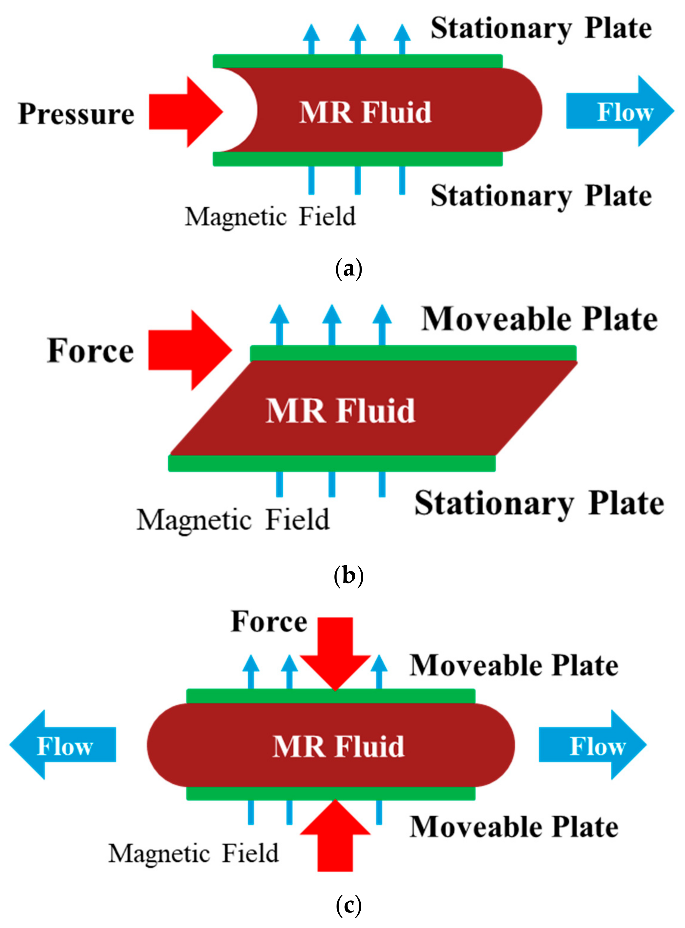
Magnetorheological (MR) fluid is a type of smart material whose rheological characteristics can be continuously controlled based on the intensity of an applied external magnetic field. MR fluid is composed of a base oil and magnetizable micro-scale iron particles, as well as additives such as surfactants. The iron particles randomly distributed in the base oil are magnetized by an externally applied magnetic field to form a chain structure, and the force required to break the chain structure serves as the actuating force in MR fluid-based actuators. Because the bonding strength of the chain structure increases proportionally to the intensity of the applied magnetic field, the actuating force can be continuously controlled by adjusting the intensity of the magnetic field. When a chain structure is formed inside a MR fluid according to the application of a magnetic field, it externally changes from a liquid phase to a solid-like phase, and this characteristic change is reversible. The operation modes of a MR actuator can be classified into flow, shear, and squeeze modes. The conceptual configuration of each mode is illustrated in Figure 1. In the flow mode, as shown in 
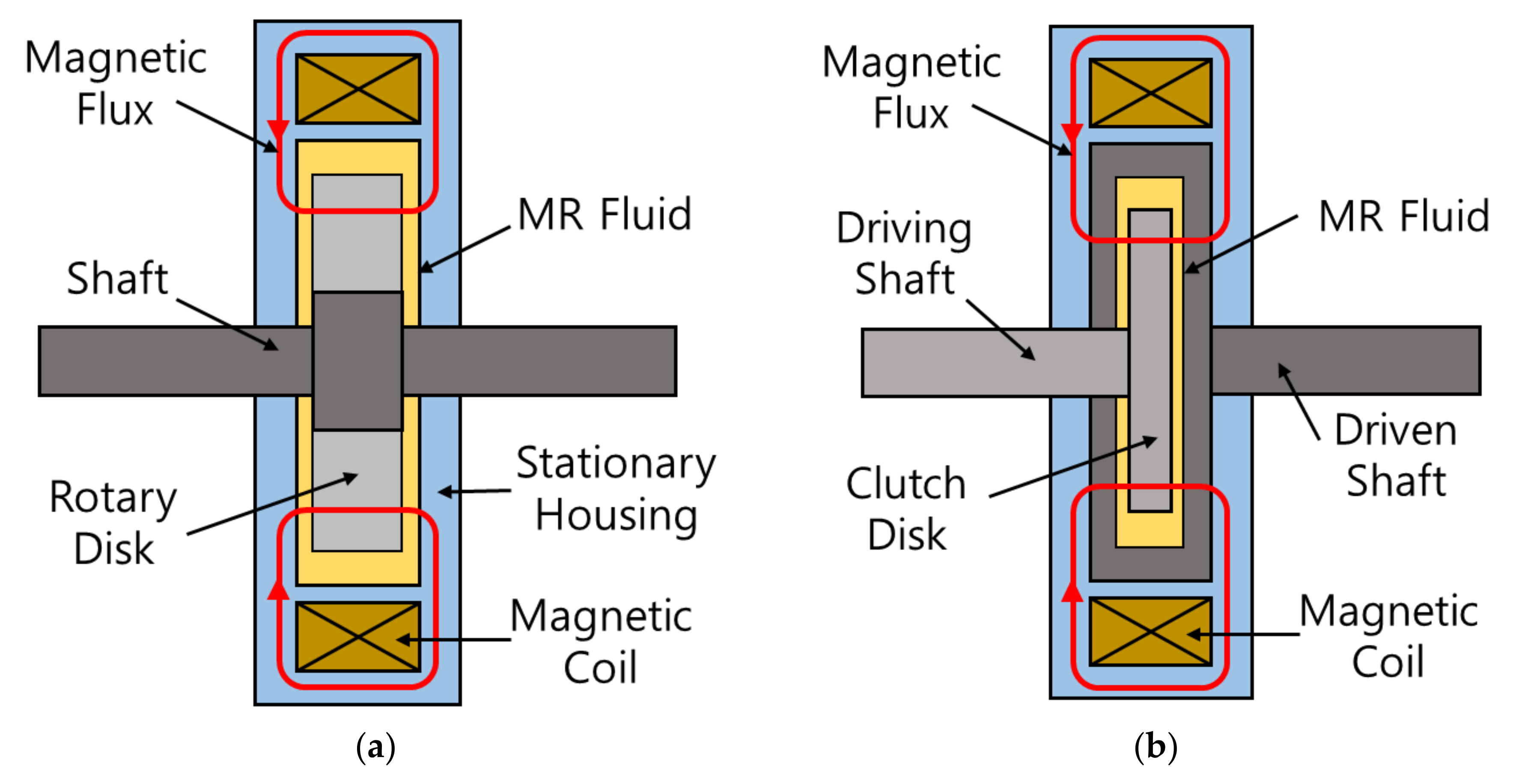
Figure 1a, the MR fluid fills the space between two stationary plates and flow occurs due to the result of the pressure difference between the two ends. A magnetic field is applied perpendicular to the flow. A damper is the most representative type of actuator that utilizes the flow mode. In the shear mode, as shown in Figure 1b, the MR fluid fills the space between a stationary plate and a sliding plate, and a magnetic field is applied in a direction perpendicular to the moving plate. For the plate to move, the chain structure formed in the MR fluid must break. The force that breaks the chain structure is expressed as an actuating force. Brakes and clutches are typical actuators that use the shear mode. In the squeeze mode, as shown in Figure 1c, the MR fluid fills the space between two moving plates. A magnetic field is applied in the same direction as the moving direction of the plates and flow occurs perpendicular to the moving direction of the plates. The squeeze mode is suitable for cases in which the displacement is small, but a large actuating force is required and is typically utilized in dampers or mounts. Actuators such as dampers, brakes, clutches, and mounts are representative devices in which MR fluid are applied. Actuators using MR fluid have the disadvantage of having to design a magnetic core for generating a magnetic field, but they have many advantages such as fast response times (less than 1 ms), low power consumption (less than 5 W for a vehicle damper), and simplicity of structural design. A unique advantage of MR actuators is that they can exhibit failsafe features without requiring additional devices, unlike conventional active actuators such as motors or passive actuators such as hydraulics. These advantages are attractive for utilizing MR actuators in various industries such as automotive engineering, aerospace engineering, manufacturing engineering, and civil engineering.
In the first part of this review article, recent research works related to MR sandwich structures, which have been extensively studied in the field of vibration and noise reduction and control, are discussed. In this study, for MR sandwich structures, a comprehensive review was performed with a focus on design configurations, modeling techniques, and control algorithms, and vibration and noise control characteristics were investigated. In the latter part of this review, recently reported MR actuators such as dampers, mounts, brakes, and clutches, are classified by application field, and the features of the newly proposed actuators are investigated. The application fields considered in this study include not only traditional automotive, aerospace, manufacturing, and civil engineering fields but also robotics, rehabilitation engineering, and haptic interfaces, which have recently received increasing attention. In particular, the degree of freedom of the system to which MR fluid actuators are applied was also considered in this review. This review article can help readers understand the design characteristics of MR actuators according to different application fields and can provide useful guidelines for the practical implementation of MR actuators in various application fields.

2. MR Sandwich Structure

There are numerous applications of MR fluid, and these applications can be classified into two sectors: traditional dynamic systems and flexible structures. In the dynamic systems, principal design objectives are force, moment, and torque focusing on the field-dependent yield stress of MR fluid itself, while the objectives are damping and stiffness properties focusing on the field-dependent complex modulus of MR fluid core of the sandwich structures. Therefore, the former sector includes a wider range of the applications than the latter such as the damping force of the MR damper and the torque control of the MR brake. The latter sector is mainly focused on the vibration control of flexible structures such as long flexible links of the space robot and flexible blades of the helicopter. The vibration control of flexible structures plays a fundamental role in various applications such as large structures in space engineering and bridge cables in civil engineering. Thus far, three different types of methods have been used to suppress or control unwanted vibrations, namely, passive, semi-active, and active methods. Passive methods provide reasonable performance using a simple methodology but have several limitations such as the lack of real-time avoidance of time-varying resonances. Active vibration control methods are very effective under uncertain environmental conditions but cause instability and incur high implementation costs based on the use of multiple actuators and sensors. Semi-active vibration control methods provide effective vibration control performance through energy dissipation using viscoelastic materials such as polymers, rubber, electrorheological fluid, and MR fluid. Recently, it has been verified that the semi-active vibration control technique using MR fluid as a core layer in sandwich structures is very promising. The generic concept for the development of sandwich structures is illustrated in Figure 2, which presents a deformable solid-embedded ME fluid domain. The specific standard structures associated with this concept include sandwich beams, sandwich plates, and sandwich shells, which contain the MR fluid domain as a core layer, as shown in Figure 2. Because these structures have the infinite degree-of-freedom, in practice, a finite multiple degree-of-freedom (multi-DOFs) is frequently considered for the identification of modal properties such as the natural frequency of each mode. In this section, sandwich structures studied over the past five years are reviewed in terms of design configuration, modeling, and control approaches in the order of sandwich beams, sandwich plates, and applications of sandwich structures. As mentioned, the passive sandwich structures have limited performance with respect to vibrations with a wide frequency range or time-varying characteristics. These limitations can be resolved by utilizing MR sandwich structures, which can be controlled continuously in a wide frequency spectrum with the robustness against external disturbances. The semi-active vibration control using MR sandwich is very attractive to a very thin structure since the structural stability is assured all the time by realizing the energy dissipation effect.
Walikar et al. fabricated a cantilever sandwich beam consisting of three layers, where the top and bottom layers were aluminum sheets and where MR fluid was encapsulated between the sheets [1]. Through experimental tests, they determined that the controllability of vibration characteristics such as the natural frequency and the damping factor can be achieved by modulating the intensity of the magnetic field applied to the MR fluid domain. Biju et al. studied the damping characteristics of a bidirectional sandwich composite beam containing the MR fluid as a core and investigated the field-dependent damping property and natural frequency with various magnet positions [2]. Kolekar et al. proposed a sandwich beam featuring the MR fluid as a core material and modeled and calculated the first-mode damping ratio and the natural frequency and compared them to measured data [3]. Naji et al. studied the vibration behavior of adaptive laminated composite beams integrated with a MR-fluid layer using a modified layer-wise displacement theory in which each layer was modeled based on the first-order shear deformation theory [4]. Romaszko and Sapinski investigated the dynamic behavior of three-layered cantilever sandwich beams filled with MR fluid with different iron-particle contents by volume [5]. They fabricated two different types of beams, namely, fully filled beams and partially filled beams, and they used free vibration tests to determine that the equivalent natural frequencies and damping coefficients of the beams could be tuned by varying the magnetic field. Nagiredla et al. fabricated a sandwich cantilever beam with glass fiber as the face layer and MR fluid as the core, and they investigated the changes in the natural frequency and damping properties when varying the magnetic field applied to the fluid domain [6]. Lahane investigated the field-dependent storage modulus and the loss factor of a cantilever sandwich beam consisting of an aluminum face material and a MR fluid core and compared the measured data to the calculated values from a 1-DOF lumped model [7]. Srinivasa et al. presented experimental and computational results regarding the changes in both the damping property and the natural frequency of a fully filled MR fluid and a partially filled MR fluid between two aluminum face plates [8]. Acharya et al. fabricated six different sandwich beams with different particle sizes and weight fractions of carbonyl iron powder (CIP). Through sinusoidal excitation tests, they determined that sandwich beams with a larger particle size and a higher weight fraction of CIP exhibited an increased damping ratio and vibration suppression [9]. Vazquez and Kauffman proposed an updated analytical model to measure sandwich beams containing MR fluid as core materials, where the modal and transient properties were related to the stiffness of the shear modulus at various magnetic-field intensities [10].
Manoharan et al. investigated the optimal locations of MR fluid pockets in partially treated laminated composite MR sandwich plates to achieve the maximum natural frequencies and loss factors, where a genetic algorithm combined with the finite element method was utilized to find the optimal locations [11]. Manoharan et al. experimentally investigated the natural frequencies of fully and partially treated laminated composite MR sandwich plates by varying the intensity of the magnetic field, boundary conditions, and location of the MR fluid pocket [12]. Arani et al. conducted vibration analysis of a viscoelastic sandwich plate consisting of a MR fluid core and nanocomposite face sheets featuring a piezoelectric matrix and functionally graded carbon nanotubes, where the influence of various parameters such as the core-to-face-sheet-thickness ratio and the magnetic field and volume fraction of iron particles on the dimensionless natural frequencies of the sandwich plate were identified [13]. Kolekar et al. reviewed different types of sandwich beams, plates, and shells featuring MR fluid cores, where the modal characteristics of several specific beams and plates were presented with the effects of the magnetic field, the location of the MR fluid pocket, and the modal excitation [14]. Eyvazian et al. considered the instability of sandwich plates consisting of a MR fluid core and piezoelectric-reinforced face sheets for vibration control using a proportional-derivative controller in which the sinusoidal shear deformation theory and the Hamilton principle according to piezo-elasticity theory were employed to calculate motion equations. These equations were solved to obtain the vibration and the modal-loss factor of the proposed sandwich plate with respect to the dimensions of the structure, the electromagnetic field, the damping of the structure, the viscoelastic environment, and the boundary conditions [15]. Asgari et al. studied the aeroelastic instability of a partially treated MR sandwich panel in supersonic airflow using the linear first-order piston theory and the classical Hamilton principle, where the critical aerodynamic pressure was affected not only by the magnetic field strength, core, and constraining layer thicknesses but also by the configuration of the core [16]. Aboutalebi et al. conducted comprehensive analysis of the nonlinear vibratory behavior of circular, annular, and sector sandwich panels containing a MR fluid as the core layer, where a finite element method based on the von Karman formulation was used to evaluate the effects of the post-yield behavior of the MR fluid on nonlinear vibration suppression under various magnetic fields [17,18].
Wang et al. investigated the vibration characteristics of a rotating sandwich beam featuring MR fluid as a core layer using the finite element method and the Hamilton principle and found that the natural frequency of the beam increased as the rotation speed and magnetic field strength increased, while the modal-loss factor decreased as the rotation speed decreased [19]. Wei et al. investigated the dynamic properties and vibration-suppression capabilities of an axially moving sandwich beam with a MR fluid core using the linear viscoelasticity theory, where the effects of the speed of the axial movement, the axial force, the applied magnetic field, and the skin-core-thickness ratio on the capabilities of the beam for natural frequency suppression were considered [20]. Arani et al. investigated the modeling and vibration analysis of double sandwich beams coupled by a visco-Pasternak medium, where the material properties of the MR fluid were obtained from experimental data, and the material properties of the carbon nanotube/fiber composite face sheets were obtained from the Halpin–Tsai model [21]. Hemmatian (Figure 3) investigated the sound-transmission loss capability of sandwich panels treated with MR-fluid cores at low frequencies. The sound transmission behavior of MR-based circular sandwich panels was investigated through the development of efficient numerical models, and the topology optimization of sandwich panels partially treated with MR fluid and a silicone rubber core layer was considered [
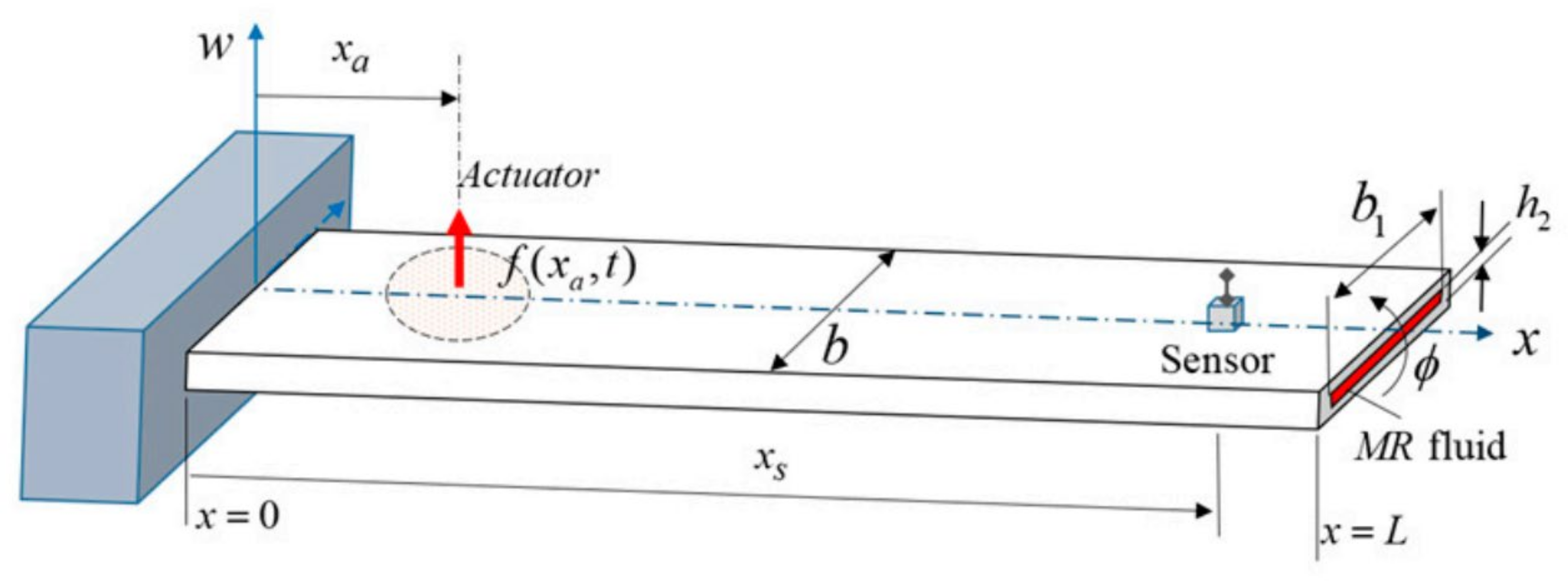
22]. Bolat and Sivrioglu (Figure 4) proposed a novel active control structure to suppress the vibrations of a small-scale wind turbine blade filled with a MR fluid core. In Figure 4, h1 is the wall thickness of the equivalent beam; h2 is the MR fluid layer thickness; b is the width of the beam; and xa and xs are the length from the wall to the actuator and the sensor position, respectively. A dynamic interaction model between the MR fluid and the electromagnetic actuator was constructed to obtain a force relationship, and the H2/H-inf controller was experimentally implemented [23]. Nezami and Gholami studied the optimal locations of a finite number of embedded MR fluid pockets using a single-objective genetic algorithm to suppress the supersonic flutter of an elastically supported sandwich beam with a regular honeycomb interlayer to achieve the optimal compromise between mass and flutter suppression, where the best number of MR pockets and optimal magnetic field values in a honeycomb sandwich structure were determined [24]. Eshaghi investigated the aeroelastic stability of sandwich plates containing MR fluid as a core layer under supersonic airflow, where the effects of the MR fluid, the magnetic field, the boundary conditions, and the plate parameters on the flutter boundaries of sandwich MR plates were analyzed [25]. Ebrahimi and Sedighi studied the wave propagation of a rectangular sandwich composite plate containing a tunable MR fluid core, and it was determined that the magnetic field intensity was the most significant factor for changing the wave frequency and the phase velocity of the propagated waves [26]. Table 1 summarizes many different recent studies on MR fluid sandwich structures.

3. MR Damper

A MR damper can generate an additional damping force based on the application of a magnetic field. As shown in Figure 5a, the upper and lower chambers are fully filled with MR fluid, which can flow through the orifice according to the movements of the piston. Since the pressure difference between the two chambers of the damper is tuned by adjusting the magnetic field intensity, the MR damper was applied to the multi-DOF application system. In this section, MR-damper studies from the past five years are reviewed in terms of design configurations, modeling, control approaches, and application fields.

3.1. Automotive Application

The damping force of a MR damper is tuned by adjusting the magnetic field intensity under various road conditions. Therefore, the desired damping force for a multi-DOF vehicle system can be achieved using a MR damper, thereby providing both ride comfort and driving stability. The advantages of MR dampers include their simple mechanism, lack of moving parts, high reliability, and excellent durability. As shown in Figure 5b, Cadillac and Audi have released various sports-car models with MR dampers. Recently, MR dampers have been used to reduce not only vertical motion but also steering motion [27,28]. Dutta et al. defined a 3-DOF dynamic model of the Macpherson strut with a MR damper, rotation of the wheel assembly, and lateral stiffness of the tire to represent the nonlinear characteristics of a Macpherson-type suspension system [27]. Additionally, a novel type of controller for regulating 4-DOF steering motions such as shimmy vibration was developed, and its control performance was evaluated [28]. To enhance ride comfort and reduce unwanted vibrations, a novel adaptive sliding mode controller was proposed by adopting a moving sliding surface. MR dampers can be applied to the seat suspensions of heavy dump trucks or buses [29]. Ride quality in heavy dump trucks or buses is very important based on its effects of safety and health issues for drivers. Therefore, a rotary-type MR seat damper was devised to reduce the transmitted vibration from the ground and increase the productivity of drivers. Additionally, Phu et al. [30,31] proposed a novel adaptive fuzzy controller associated with the H-infinity technique for 2-DOF vehicle seat suspension, as shown in Figure 6. When using an adaptive controller, vibration control performance was significantly better than that when using a fuzzy controller. Table 2 summarizes many different recent studies on MR dampers for automotive application.

3.2. Civil-Engineering Application

Based on their large damping force, MR dampers are widely used in multi-DOF bridges and civil structures [32]. During an earthquake, such structures exhibit nonlinear behaviors. Accordingly, an actuator and control method for structural nonlinear vibrations are required. In this review, several studies related to MR dampers for the seismic resistance of structures are briefly discussed. It is widely known that MR dampers can reduce the earthquake responses and wind-induced swaying of buildings. Li et al. [33] proposed a sliding-mode control method and a fuzzy controller based on the complexity of structures and the chattering phenomenon. A MR damper and building model were modeled using the revised Bingam model and a third-generation nonlinear benchmark model. The control performance was evaluated through numerical simulations, and the control results revealed the effectiveness of the proposed methods. Cruze et al. [34] numerically investigated the time-history analysis of structures, including peak acceleration and displacement data. Based on their analysis results, the optimal control inputs were calculated according to various control algorithms. Mahdi et al. [35] reported the fuzzy control performance of a three-story building. According to the control results, the displacement of the building was reduced compared to uncontrolled buildings. Omar et al. [36] examined the seismic responses of multistory buildings with MR dampers. The SAC method was utilized to regulate the behavior of a MR damper. An adaptive controller can properly handle the structural feature changes that occur during earthquakes [36,37]. Talatahari et al. [38,39] studied the alternative modeling of a MR damper using a Takagi–Sugeno–Kang (TSK) fuzzy inference system. Subsequently, a linear quadratic regulator controller was designed to calculate the optimal control force of a MR damper. Experiments revealed that the proposed inverse TSK model of the MR damper could provide highly competitive results for a several-story shear building with a MR damper. Table 3 summarizes many different recent studies on MR dampers for civil engineering.

3.3. Military and Railway Application

A MR damper can be used to generate a shockwave profile, as shown in Figure 7 [40,41,42]. Because the electric devices in submarines are damaged by shockwaves caused by noncontact explosions, impact examinations should be implemented to verify shock survivability according to shock loading. The controllability of a MR impact damper can be used to modify and tune shockwave profiles. Oh et al. designed a control logic for a MR damper and evaluated its control performance [41]. An experimental apparatus for impact tests was constructed, and field-dependent dual shockwave profiles were successfully evaluated [41,42]. The vibrations of a 15-DOF high-speed railway system cause poor ride quality and track abrasion. Several studies have been conducted to solve this problem [43,44]. Oh et al. proposed a MR damper attached between the bogie frame and car body [43]. By designing a fuzzy skyhook controller, the vibration control performance at the critical natural frequency range of the car body, which directly affects ride quality, was significantly enhanced. Kim et al. [44] evaluated the control performance through field tests. The research team of Prof. Kumar designed several control algorithms for MR dampers in railway systems, including disturbance rejection control [45] and predictive model control [46]. Based on the control results, it was confirmed that the vertical vibrations of railway vehicles can be significantly reduced using the proposed semi-active suspension strategies. Recently, Jin et al. [47] developed a novel type of semi-active suspension featuring a MR damper and elastomer. Table 4 summarizes many different recent studies on MR dampers for military and railway engineering.

3.4. Rehabilitation Application

Based on the advantages of MR fluid, which can control stiffness and damping properties, many studies have reported prosthetic knee applications using MR dampers. Park et al. [48] manufactured a prosthetic leg for above-knee amputees featuring a MR damper and a flat motor. The proposed device consists of a wearable connector, an encoder, a flat motor, planetary gear, a gyro sensor, a hinge, and a MR damper. The MR damper generates a reaction force, whereas the commutated flat motor actively controls the knee joint angle during the gait cycle. It was demonstrated that the knee joint angle accurately follows the desired angle at a low walking velocity. They concluded that a MR damper with a slow response time and an inaccurate algorithm for the gait cycle for predicting the knee angle degrades tracking performance at high walking velocities. Additionally, Pandit et al. [49] devised a novel type of prosthetic leg that includes a MR damper, a hinge-type knee joint, and braces to support the leg assembly. To reduce the cost of the proposed prosthetic leg, a single-MR-damper-based knee joint mechanism was proposed, which can realize normal gait kinematics at a low cost comparable to that of passive prostheses. Recently, Wang et al. [50] proposed a finger rehabilitation robot for active and passive training. To fulfill the requirements of different rehabilitation stages, an antagonistic pair of pneumatic muscles was used to generate a bidirectional force for passive training, and a MR damper was utilized for active training. The current of the MR damper was tuned to provide several damping forces to satisfy the required intensity of the finger muscles during various rehabilitation stages.

3.5. Washing-Machine Application

Nguyen et al. developed a MR damper to control the vibration of 2-DOF washing machines [51,52]. Because the MR damper was installed inside the washing machine, the damper size was constrained. To solve this problem, Nguyen et al. proposed an optimal design technique using finite element analysis. The optimal geometric parameters of the MR damper for the washing machine were obtained from the finite element analysis results. Subsequently, an experimental test was conducted to analyze the hysteresis behavior of the MR damper [51]. Additionally, a novel type of self-powered shear-mode MR damper was proposed to reuse the wasted energy from the vibration of washing machines. To generate energy, permanent magnets were attached to the shaft, and induction coils were wound on the slots of the housing. When a harmonic excitation with a 2.4 Hz frequency and a 30 mm amplitude was applied to the MR damper, it was determined that the maximum power generation was approximately 19 W [52].

3.6. Aircraft Landing-Gear Application

Aircraft landing gears are used to reduce the transferred landing force on the airplane body. Passive oleo-pneumatic landing gears are widely used for their high landing efficiency per unit weight. However, this type of passive landing gear cannot obtain optimal performance under all design conditions. To overcome the limitations of passive landing gears, semi-active MR dampers with two chambers have been proposed for application to airplane landing-gear systems. To control MR landing-gear systems, a conventional skyhook controller can be applied to such systems. Although the landing efficiency of a skyhook controller is better than that of a passive landing gear system, the dependency of a skyhook controller on the airplane velocity limits performance enhancement. To resolve this limitation, hybrid controllers composed of a force controller and a skyhook controller have been proposed and applied to MR landing-gear systems [53,54,55]. Figure 8 presents a 6-DOF aircraft model with a MR damper for its landing gear. In Figure 8a, it was set to generalized coordinates for 6-DOF aircraft motion for the translational displacement in the Z-direction on P0, the rotational displacements of the pitch angle θ and roll angle ϕ, and the damping strokes of the nose gear and the right and left main gears. Moreover, the MR damper’s response to various fuselage postures and controllers was analyzed by drop simulation of the 6-DOF aircraft model as shown in Figure 8b. Based on this full-scale model, the landing stability and efficiency of the hybrid controller were much better than those of a conventional skyhook controller.

3.7. MR Mount Applications

It is widely known that various mechanical systems are exposed to both vertical and horizontal vibrations with high frequencies and low magnitudes. One type of mount is suitable for vibration-reduction applications in such systems because the magnitude of vibrations is very small. Passive mounts such as rubber or air springs are widely used based on their economic feasibility. However, conventional mounts cannot be used effectively to control unwanted vibrations. Therefore, semi-active-type mounts are recommended based on their failsafe functions and controllability. Among the many actuators available for semi-active-type mounts, MR fluid has been highlighted for their fast response time, simple control strategy, and failsafe conditions. Additionally, the appearance of high-load MR mounts has recently been highlighted, and their application has been extended to vibration-controlled automotive engine systems. It should be noted that MR mounts are very similar to conventional hydraulic mounts, but their capacity and controllability are significantly different. Therefore, a broad review of automotive semi-active MR mounts can help designers develop more advanced structures.
In 2010, MR engine mounts were applied to the Porsche GT3 and GT2. A MR engine mount can reduce the relative motion between the power train and chassis. In 2016, Choi et al. proposed a shear-flow hybrid-type MR mount [56,57]. Yang et al. evaluated the performance of a MR mount from the perspective of a comfortable ride for passengers and drivers [56,57]. Li et al. [58] constructed and verified a steady-state model of a squeeze-type MR mount by considering the responses in the squeeze mode, the fluid viscosity, and the fluid inertia. Bai et al. proposed a novel unidirectional MR squeeze mount with a small amount of MR fluid [59,60]. This can significantly reduce the cost of MR mounting systems. However, the controllability of the MR squeeze mount is limited by the squeeze gap. To maximize controllability, Liu et al. [61] devised a novel mechanism for a MR mount with an internal bypass. Because the MR fluid channel consists of inner and outer concentric cylinders and the piston divides the inner cylinder, the proposed MR mount has many benefits such as a large controllable range and working stroke and small field-off dynamic stiffness. Both the frequency-based controller and the fuzzy controller were synthesized, and the control performance was evaluated through computer simulations and experimental tests. Based on the control results, it was confirmed that the results of the frequency-based controller were always better than those of the fuzzy controller in the full frequency range.
To fabricate sophisticated patterns without excessive vibration transmission, 3-DOF precision manufacturing stages have been used. To obtain high-quality products, efficient vibration-isolation devices such as hybrid MR mounts are required. Generally, a hybrid MR mount consists of an air chamber (passive), a small MR damper (semi-active), and an electromagnetic (EM) coil actuator (active). However, this system has three drawbacks: control input interference, expensive commercial control boards, and large mount sizes based on the inclusion of an EM actuator. To overcome these drawbacks, Han et al. [62] proposed a simple hybrid mount consisting of an air spring and a small MR damper, as shown in Figure 9. By eliminating the EM actuators, a simpler mechanism, robustness to noise and disturbance, and cost effectiveness can be obtained. Additionally, it has been confirmed that unwanted vibrations are significantly reduced in the operating frequency range (up to 30 Hz), and a fast settling time is obtained. Table 5 summarizes many different recent studies on MR mounts.

4. MR Brake/Clutch

MR brakes and clutches are actuators that can control torque on a rotating device. The purpose of the MR brake is to reduce the rotation speed or stop rotation completely to transmit the rotational force from one shaft to another shaft. A MR brake is configured in the form of a fixed housing and rotating core, and the MR fluid fills the space between the core and the housing. A MR clutch consists of one pair of rotating cores, another individual rotating core, and a rotating housing. The MR fluid fills the space between the cores or between the core and the housing. A core is designed in the form of a disk or drum, and the MR effect is generated in the MR fluid in the flow mode or the shear mode. The schematic configurations of a MR brake and clutch are presented in Figure 10. Phu and Choi presented a mini-review article on MR brakes and clutches reported from 2013 to 2018 with a focus on their structural configurations [63]. Hua et al. reviewed the state of the art based on the structural configurations of MR brakes and clutches developed between 2018 and 2021 [64]. In this section, MR brakes and clutches developed from 2015 to 2021 are summarized according to their fields of application.

4.1. Vehicle Application

In an effort to apply MR brakes and clutches in the vehicle-engineering field, various studies have been conducted, and many have been reported in recent years. Sohn et al. [65] proposed a single-disc-type MR brake for midsize motorcycle applications, as shown in Figure 11. Design parameters such as the radius of the disc, the gap size, and the coil dimensions were optimized through finite element analysis, and the braking torque of the manufactured MR brake was evaluated experimentally. Yu et al. [66] presented a new design for a MR brake featuring a multipath magnetic circuit using permanent magnets to achieve enhanced braking torque for vehicle applications. After determining the design parameters through finite element analysis and experiments on the fabricated prototype, a full-scale prototype was fabricated, and its feasible application in automotive braking was validated. However, based on the large size of the proposed MR brake model, its practical realization and maintenance are difficult. Shamieh and Sedaghati [67] formulated a multidisciplinary design-optimization problem to identify the optimal geometrical parameters of a MR brake to improve the slipping of vehicles under different road conditions. After solving the optimization problem, the performance of an optimally designed MR brake was investigated using a quarter-vehicle model. Le et al. [68] conducted design-parameter optimization on a MR brake for motorcycle applications with multiple objectives, including maximizing braking torque, minimizing brake mass, and limiting the temperature to below a critical value. They considered the design of rectangular and polygonal-shaped housings and side-coil configurations. In addition, they compared the braking performance of different models. Hasannasab and Bazargan-Lari [69] designed and manufactured a MR brake for wheelchair handling under low-weight constraints. Based on finite-element-analysis results, a prototype was manufactured, and its braking performance was evaluated by confirming good agreement between the experimental- and numerical-analysis results. Le et al. [70] developed a MR brake featuring a rotating disc with multiple trapezoidal teeth for small motorcycle applications. To obtain a high braking torque, multiple poles with trapezoidal shapes were adopted, and the size of the brake was kept compact. Tri et al. [71] developed a MR brake for application in a cycling training system. They adopted a dual disc and a dual coil to obtain a higher braking torque by increasing the contact area between the MR fluid and the disc. After optimizing the design parameters, a prototype was fabricated; its braking performance was validated; and good agreement between the experimental and numerical simulation results was confirmed. Wang et al. [72] proposed a multidisc MR clutch for vehicle applications. To overcome the high-temperature problem that degrades the performance of MR clutches in vehicle applications, the transient temperature was investigated through experiments and numerical simulations. East et al. [73] presented a new application of a MR clutch to an automotive active suspension system. They compared the experimental results to those of previous studies and verified that an active suspension system that can efficiently control vibrations can be constructed by applying a MR clutch to a suspension consisting of an electric motor, rack, and pinions. Lokhande and Patil [74] designed and manufactured a MR clutch for two-wheeled electric-vehicle applications. The torque transmission capabilities of the MR clutch with and without slits were evaluated analytically and experimentally, and an increase in torque transmission caused by the presence of slits was validated. Table 6 summarizes many different recent studies on MR brakes/clutches for vehicle application.

4.2. Haptic Device Application

Haptic systems are the most researched field of MR brake and clutch applications along with the vehicle-engineering field, and interest in this field has been continuously increasing. MR brake and clutch actuators have fast response times and excellent energy efficiency. Thus, these are expected to replace existing electric motor and gear actuators with compact system configurations. Various studies have been conducted on these applications. Gonenc and Gurocak [75] developed a hybrid haptic device composed of a DC servomotor and MR brake for the training of tissue cutting with surgical scissors. The proposed haptic actuator was implemented using a compact 1-DOF interface to simulate virtual tissue cutting using three different scissor types and four types of rat tissue. It was demonstrated that the hybrid actuator provided a wide range of forces with rapid responses to render rapid force variations without any instability for all compared tissues using only a DC motor. Cinq–Mars and Gurocak [76] proposed a novel linear hybrid actuator consisting of a pneumatic cylinder with a MR brake embedded in its piston to develop a haptic actuator with a high force-to-weight ratio. They investigated a triple-helix flux guide for the linear MR brake and a serpentine flux path to enable larger braking forces, as well as control algorithms that enable the use of simple solenoid valves and improved power efficiency. Cha et al. [77] designed a haptic master with 6-DOFs that can be applied to robot-assisted minimally invasive surgeries. The proposed haptic master is activated by both a MR brake and a clutch. For successful tracking control performance, a fuzzy plus proportional-integral-derivative feedback controller was used for the repulsive force, and a feed-forward controller was associated with a hysteretic compensator for the repulsive torque. Qin et al. [78] proposed a MR brake for a haptic actuator based on desirable features such as inherent passiveness and high compactness. To achieve enhanced braking torque within a small-limited volume, they adopted a multi-disc architecture. They applied this MR brake actuator to multi-finger interface for the 6-DOF haptic device. Kang et al. [79] presented controllable MR-fluid-based actuators for the design of a novel 6-DOF haptic master that can be applied to robot-assisted surgery, as shown in Figure 12. A MR clutch was adopted for the three-axis translational motion of the haptic master body, and a MR brake was used for the rotational motion of the end effector in the slave robot. Sohn et al. [80] proposed a small MR brake featuring a trapezoidal drum structure to achieve enhanced braking torque with a limited size. After manufacturing a MR brake, it was experimentally verified that the proposed MR brake provided improved braking torque compared to a conventional MR brake. The dynamic characteristics and torque-tracking control performance were also evaluated through an investigation of the step, sinusoidal, and multi-magnitude step responses. Gang et al. [81] proposed a 3-DOF master device for teleoperation, and MR brakes were adopted to generate a haptic effect on the operator’s three-axis wrist motions. After manufacturing the master device and the slave robot, the performance of the proposed system was experimentally validated in terms of the tracking control of the desired position and the repulsive torque. Wang et al. [82] developed a data glove featuring a MR-brake-based haptic actuator and experimentally investigated its force-feedback performance. The results verified the feasibility and stability of the proposed force-feedback data glove by demonstrating feedback force tracking control accuracy. Diep et al. [83] proposed a 3-DOF haptic master device for teleoperation featuring a spherical arm mechanism and three MR brakes. The authors adopted two rotary brakes and one linear brake for independent three-axis force feedback to the operator. Okui et al. [84] developed a force-feedback device actuated by pneumatic artificial muscles and a MR clutch. The authors manufactured a delta-type 4-DOF (one rotation and three translations) haptic master device and applied it to perform lid opening. Wellborn et al. [85] designed a small-scale MR brake for haptic applications, and its performance was experimentally validated. By combining the disk-type and drum-type designs and incorporating coils into the rotor, all three shear surfaces of the rotor were utilized to generate a large braking torque. Table 7 summarizes many different recent studies on MR brakes/clutches for haptic device application.

4.3. Rehabilitation Application

Wang et al. [86] proposed a MR brake for application in gait-rehabilitation robots. A structure that can expand the area in which the MR effect occurs was adopted to satisfy the high operating force required for the gait-rehabilitation robot. After manufacturing the proposed MR brake, its mechanical performance was investigated, and brake properties such as torque versus speed and yield torque versus current were evaluated. Sayyaadi and Zareh [87] investigated a prosthetic knee with one activating rotary disc to achieve the necessary braking torque in a walking gait using a T-shaped drum with an arc surface boundary. The T-shaped disc increased the effective areas of influence between the drum and the MR fluid, and the arc wall crushed the particle chains of the MR fluid together instead of breaking them, unlike a conventional MR brake. Ma et al. [88] developed a MR brake with power-regeneration capabilities called a regenerative MR actuator for gait assistance in the knee joint, as shown in Figure 13. Both the motor and MR brakes work in parallel and can harvest energy through regenerative braking. Andrade et al. [89] presented an active MR knee actuator developed for transfemoral prostheses. Their system consists of a motor unit, a harmonic drive, and a MR brake. The motor unit provides active motion and works in parallel with the MR brake. With this configuration, the actuator possesses multiple functions. It can serve as a motor, a clutch, or a brake, allowing it to reproduce movements similar to those of a healthy knee during different activities. Mousavi and Sayyaadi [90] developed a prosthetic knee featuring a hybrid MR brake with a T-shaped disc and an arc-shaped surface boundary. The authors performed a three-step process to achieve successful development. In the first step, to model the MR brake, the slab-modeling method was used to calculate the braking torque induced by the arc surface. In the second step, the biomechanical geometric design was adjusted as an optimization problem to maximize the braking torque, minimize the instantaneous electrical power dissipation, and maximize the torque density based on three biomechanical constraints. In the third step, the proposed prosthetic knee was verified through simulations and experiments. Xu et al. [91] presented an 8-DOF rehabilitation robot system with a MR actuator that allows for two working modes, namely, robot-active and human-active modes. In the robot-active mode, the MR actuator functions as a clutch to transfer torque to the robotic joint safely. In the human-active mode, the MR actuator functions as a brake to provide resistance to help strengthen muscles. The working mode is determined by human motion intention, which is detected by skin-surface electromyography signals. Table 8 summarizes many different recent studies on MR brakes/clutches for rehabilitation application.

4.4. Robot Application

As shown in Figure 14, Baser and Demiray [92] investigated the design, characterization, selection, and implementation of T-shaped, inner coil, and outer coil multipole MR brakes for the ankle of an exoskeleton robot. Prototypes of the same size were manufactured and tested experimentally to characterize their torque-to-volume ratio, transient response, hysteresis, torque-tracking, energy consumption, and damping performance. The performance comparisons of the brakes revealed that the T-shaped multipole MR brake design provided superior characteristics compared to the other two designs. Kim et al. [93] developed a multi-disk-type MR brake with three modules for wearable robot driving. Each module consisted of three disks and one coil to achieve an enhanced actuating torque with a limited volume. Two prototypes were constructed: one to verify the performance of the manufactured MR brake and the other to check the generated torque and response characteristics according to the applied voltage. Wang et al. [94] evaluated series clutch actuators with high torque-to-weight ratios for open-loop torque control and collision safety. To overcome the disadvantages of a MR clutch, particularly its relatively low torque-to-weight ratio, which makes integration into robots difficult, series clutch actuators were proposed, and their superiority was demonstrated. Moghani and Kermani [95] presented the design and validation of a lightweight MR clutch called a hybrid MR clutch. Their clutch utilized hybrid magnetization based on an electromagnetic coil and a permanent magnet. The electromagnetic coil can adjust the magnetic field generated by the permanent magnet to the desired value and can fully control the transmitted torque. A prototype of the hybrid MR clutch was fabricated, and its dynamic performance was experimentally validated. Table 9 summarizes many different recent studies on MR brakes/clutches for robot application.

5. Conclusions

In this review article, numerous multi-DOF MR applications including MR sandwich structures, MR dampers, MR mounts, MR brakes, and MR clutches were adopted and discussed. Based on the inherent and salient properties of MR fluid, the research progress in the development of MR applications has become very fast, and the research topics are still active and attractive. This review identified that an appropriate design configuration, modeling, and control approach are crucial factors in the commercial development of advanced MR-fluid-application devices and systems. Among the many design requirements for successful practical realization or commercialization of MR application systems, geometry configurations, working principles, dynamic modeling, and control approaches must be carefully considered, and this point has been emphasized in this review article. In addition, this review article described the inherent advantages and disadvantages of each MR application to be explored more in the future. Consequently, the comprehensive discussion on various multi-DOF dynamic systems presented in this review article will provide very useful guidelines to create and develop more advanced multi-DOF MR-fluid-application systems in various fields including automotive, civil, and medical engineering.

Author Contributions

Conceptualization, S.-B.C.; formal analysis, J.-S.O.; investigation, J.-S.O.; writing—original draft preparation, J.-S.O., J.W.S. and S.-B.C.; writing—review and editing, J.W.S. and S.-B.C.; supervision, S.-B.C.; funding acquisition, J.W.S. All authors have read and agreed to the published version of the manuscript.

Funding

This research was supported by the MSIT (Ministry of Science and ICT), Korea, under the Grand Information Technology Research Center support program (IITP-2022-2020-0-01612) supervised by the IITP (Institute for Information & communications Technology Planning and Evaluation).

Institutional Review Board Statement

Not applicable.

Informed Consent Statement

Not applicable.

Conflicts of Interest

The authors declare no conflict of interest.

References

  1. Walikar, C.A.; Kolekar, S.; Hanumantharaya, R.; Raju, K. A study on vibration characteristics of engine oil based magnetorheological fluid sandwich beam. J. Mech. Eng. Autom. 2015, 5, 84–88. [Google Scholar]
  2. Joy, R.; George, R.M.; Varghese, T. Magneto-rheological Fluid Assisted Vibration Damping in Bi-directional Composite Beam. IJSTE 2016, 2, 158–161. [Google Scholar]
  3. Kolekar, S.; Venkatesh, K.; Oh, J.; Choi, S. The tenability of vibration parameters of a sandwich beam featuring controllable core: Experimental Investigation. Adv. Acoust. Vib. 2017, 2017, 5674032. [Google Scholar] [CrossRef] [Green Version]
  4. Naji, J.; Zabihollah, A.; Behzad, M. Vibration behavior of laminated composite beams integrated with magnetorheological fluid layer. J. Mech. 2017, 33, 417–425. [Google Scholar] [CrossRef]
  5. Romaszko, M.; Sapiński, B. Stiffness and damping characteristics of MR fluid-based sandwich beams: Experimental study. J. Theor. Appl. Mech. 2018, 56, 571–583. [Google Scholar] [CrossRef] [Green Version]
  6. Nagiredla, S.; Joladarashi, S.; Kumar, H. Experimental investigation of frequency and damping characteristics of magneto-rheological fluid core sandwich beams. AIP Conf. Proc. 2020, 2247, 020007. [Google Scholar]
  7. Lahane, A.B. Vibration analysis of magnetorheological fluid sandwich beam. JETIR 2020, 7, 1873–1881. [Google Scholar]
  8. Srinivasa, N.; Gurubasavaraju, T.M.; Kumar, H.; Arun, M. Vibration analysis of fully and partially filled sandwiched cantilever beam with Magnetorheological fluid. J. Eng. Sci. Technol. 2020, 15, 3162–3177. [Google Scholar]
  9. Acharya, S.; Allien, V.J.; NP, P.; Kumar, H. Dynamic behavior of sandwich beams with different compositions of magnetorheological fluid core. Int. J. Smart Nano Mater. 2021, 12, 88–106. [Google Scholar] [CrossRef]
  10. Vazquez, C.G.; Kauffman, J.L. Updated Model of a Magnetorheological Sandwich Beam for Transient Magnetic Field Damping. In Proceedings of the AIAA Scitech 2021 Forum, Virtual Event, 11–15 & 19–21 January 2021; p. 0478. [Google Scholar]
  11. Manoharan, R.; Vasudevan, R.; Jeevanantham, A.K. Optimal layout of a partially treated laminated composite magnetorheological fluid sandwich plate. Smart Struct. Syst. 2015, 16, 1023–1047. [Google Scholar] [CrossRef]
  12. Manoharan, R.; Vasudevan, R.; Sudhagar, P.E. Semi-active vibration control of laminated composite sandwich plate-an experimental study. Arch. Mech. Eng. 2016, 63, 367–377. [Google Scholar] [CrossRef] [Green Version]
  13. Ghorbanpour Arani, A.; BabaAkbar Zarei, H.; Eskandari, M.; Pourmousa, P. Vibration behavior of visco-elastically coupled sandwich beams with magnetorheological core and three-phase carbon nanotubes/fiber/polymer composite facesheets subjected to external magnetic field. J. Sandw. Struct. Mater. 2019, 21, 2194–2218. [Google Scholar] [CrossRef]
  14. Kolekar, S.; Venkatesh, K.; Oh, J.; Choi, S. Vibration controllability of sandwich structures with smart materials of electrorheological fluids and magnetorheological materials: A review. J. Vib. Eng. Technol. 2019, 7, 359–377. [Google Scholar] [CrossRef]
  15. Eyvazian, A.; Hamouda, A.M.; Tarlochan, F.; Mohsenizadeh, S.; Dastjerdi, A.A. Damping and vibration response of viscoelastic smart sandwich plate reinforced with non-uniform graphene platelet with magnetorheological fluid core. Steel Compos. Struct. 2019, 33, 891–906. [Google Scholar]
  16. Asgari, M.; Rayyat Rokn-Abadi, M.; Yousefi, M.; Haddadpour, H. Aeroelastic analysis of a sandwich panel with partially treated magneto-rheological fluid core. J. Intell. Mater. Syst. Struct 2019, 30, 140–154. [Google Scholar] [CrossRef]
  17. Aboutalebi, R.; Eshaghi, M.; Taghvaeipour, A. Nonlinear vibration analysis of circular/annular/sector sandwich panels incorporating magnetorheological fluid operating in the post-yield region. J. Intell. Mater. Syst. Struct 2021, 32, 781–796. [Google Scholar] [CrossRef]
  18. Aboutalebi, R.; Eshaghi, M.; Hemmatian, M.; Sedaghati, R. Post-yield characteristics of magnetorheological fluids; from modelling to large-amplitude vibration analysis of sandwich plates using nonlinear finite element method. Aerosp. Sci. Technol. 2021, 110, 106508. [Google Scholar] [CrossRef]
  19. Wang, H.; Ma, B.; Li, S. Vibration characteristics of a rotating sandwich beam with magnetorheological fluid. J. Vibroeng. 2015, 17, 92–100. [Google Scholar]
  20. Wei, M.; Sun, L.; Hu, G. Dynamic properties of an axially moving sandwich beam with magnetorheological fluid core. Adv. Mech. Eng. 2017, 9, 1687814017693182. [Google Scholar] [CrossRef] [Green Version]
  21. Ghorbanpour Arani, A.; BabaAkbar Zarei, H.; Haghparast, E. Vibration response of viscoelastic sandwich plate with magnetorheological fluid core and functionally graded-piezoelectric nanocomposite face sheets. J. Vib. Control 2018, 24, 5169–5185. [Google Scholar] [CrossRef]
  22. Hemmatian, M.; Sedaghati, R. Sound transmission analysis of MR fluid based-circular sandwich panels: Experimental and finite element analysis. J. Sound Vib. 2017, 408, 43–59. [Google Scholar] [CrossRef]
  23. Bolat, F.C.; Sivrioglu, S. Active control of a small-scale wind turbine blade containing magnetorheological fluid. Micromachines 2018, 9, 80. [Google Scholar] [CrossRef] [PubMed] [Green Version]
  24. Nezami, M.; Gholami, B. Optimal locations of magnetorheological fluid pockets embedded in an elastically supported honeycomb sandwich beams for supersonic flutter suppression. Eur. J. Mech.-A/Solids 2019, 74, 81–95. [Google Scholar] [CrossRef]
  25. Eshaghi, M. The effect of magnetorheological fluid and aerodynamic damping on the flutter boundaries of MR fluid sandwich plates in supersonic airflow. Eur. J. Mech.-A/Solids 2020, 82, 103997. [Google Scholar] [CrossRef]
  26. Ebrahimi, F.; Sedighi, S.B. Wave propagation analysis of a rectangular sandwich composite plate with tunable magneto-rheological fluid core. J. Vib. Control. 2021, 27, 1231–1239. [Google Scholar] [CrossRef]
  27. Dutta, S.; Choi, S. A nonlinear kinematic and dynamic modeling of Macpherson suspension systems with a magneto-rheological damper. Smart Mater. Struct. 2016, 25, 035003. [Google Scholar] [CrossRef]
  28. Dutta, S.; Choi, S. Control of a shimmy vibration in vehicle steering system using a magneto-rheological damper. J. Vib. Control 2018, 24, 797–807. [Google Scholar] [CrossRef]
  29. Sun, S.S.; Ning, D.H.; Yang, J.; Du, H.; Zhang, S.W.; Li, W.H. A seat suspension with a rotary magnetorheological damper for heavy duty vehicles. Smart Mater. Struct. 2016, 25, 105032. [Google Scholar] [CrossRef]
  30. Phu, D.X.; Quoc Hung, N.; Choi, S. A novel adaptive controller featuring inversely fuzzified values with application to vibration control of magneto-rheological seat suspension system. J. Vib. Control 2018, 24, 5000–5018. [Google Scholar] [CrossRef]
  31. Phu, D.X.; Choi, S.; Choi, S. A new adaptive hybrid controller for vibration control of a vehicle seat suspension featuring MR damper. J. Vib. Control 2017, 23, 3392–3413. [Google Scholar] [CrossRef]
  32. Weber, F.; Distl, H. Amplitude and frequency independent cable damping of Sutong Bridge and Russky Bridge by magnetorheological dampers. Struct. Control Health Monit. 2015, 22, 237–254. [Google Scholar] [CrossRef]
  33. Li, L.; Liang, H. Semiactive control of structural nonlinear vibration considering the MR damper model. J. Aerosp. Eng. 2018, 31, 04018095. [Google Scholar] [CrossRef]
  34. Cruze, D.; Gladston, H.; Immanuel, S.; Loganathan, S.; Dharmaraj, T.; Solomon, S.M. Experimental investigation on magnetorheological damper for RCC frames subjected to cyclic loading. Adv. Civ. Eng. Mater. 2018, 7, 413–427. [Google Scholar] [CrossRef]
  35. Abdeddaim, M.; Ounis, A.; Shrimali, M.K.; Datta, T.K. Retrofitting of a weaker building by coupling it to an adjacent stronger building using MR dampers. Struct. Eng. Mech. 2017, 62, 197–208. [Google Scholar] [CrossRef]
  36. Al-Fahdawi, O.A.; Barroso, L.R.; Soares, R.W. Utilizing the adaptive control in mitigating the seismic response of adjacent buildings connected with MR dampers. In Proceedings of the 2018 Annual American Control Conference (ACC), Milwaukee, WI, USA, 27–29 June 2018; pp. 912–917. [Google Scholar]
  37. Fali, L.; Djermane, M.; Zizouni, K.; Sadek, Y. Adaptive sliding mode vibrations control for civil engineering earthquake excited structures. Int. J. Dyn. Control 2019, 7, 955–965. [Google Scholar] [CrossRef]
  38. Raeesi, F.; Azar, B.F.; Veladi, H.; Talatahari, S. An inverse TSK model of MR damper for vibration control of nonlinear structures using an improved grasshopper optimization algorithm. Structures 2020, 26, 406–416. [Google Scholar] [CrossRef]
  39. Azar, B.F.; Veladi, H.; Raeesi, F.; Talatahari, S. Control of the nonlinear building using an optimum inverse TSK model of MR damper based on modified grey wolf optimizer. Eng. Struct. 2020, 214, 110657. [Google Scholar] [CrossRef]
  40. Kim, H.; Oh, J.; Choi, S. The field-dependent shock profiles of a magnetorhelogical damper due to high impact: An experimental investigation. Smart Mater. Struct. 2014, 24, 025008. [Google Scholar] [CrossRef]
  41. Oh, J.; Lee, T.; Choi, S. Design and analysis of a new magnetorheological damper for generation of tunable shock-wave profiles. Shock Vib. 2018, 2018, 8963491. [Google Scholar] [CrossRef] [Green Version]
  42. Oh, J.; Shul, C.W.; Kim, T.H.; Lee, T.; Son, S.; Choi, S. Dynamic analysis of sphere-like iron particles based magnetorheological damper for waveform-generating test system. Int. J. Mol. Sci. 2020, 21, 1149. [Google Scholar] [CrossRef] [Green Version]
  43. Oh, J.; Shin, Y.; Koo, H.; Kim, H.; Park, J.; Choi, S. Vibration control of a semi-active railway vehicle suspension with magneto-rheological dampers. Adv. Mech. Eng. 2016, 8, 1687814016643638. [Google Scholar] [CrossRef] [Green Version]
  44. Kim, H.; Shin, Y.; You, W.; Jung, K.C.; Oh, J.; Choi, S. A ride quality evaluation of a semi-active railway vehicle suspension system with MR damper: Railway field tests. Proc. Inst. Mech. Eng. Part F J. Rail Rapid Transit 2017, 231, 306–316. [Google Scholar] [CrossRef]
  45. Sharma, S.K.; Kumar, A. Ride performance of a high speed rail vehicle using controlled semi active suspension system. Smart Mater. Struct. 2017, 26, 055026. [Google Scholar] [CrossRef]
  46. Sharma, S.K.; Lee, J. Design and development of smart semi active suspension for nonlinear rail vehicle vibration reduction. Int. J. Struct. Stab. Dyn. 2020, 20, 2050120. [Google Scholar] [CrossRef]
  47. Jin, T.; Liu, Z.; Sun, S.; Ren, Z.; Deng, L.; Yang, B.; Christie, M.D.; Li, W. Development and evaluation of a versatile semi-active suspension system for high-speed railway vehicles. Mech. Syst. Signal. Processing 2020, 135, 106338. [Google Scholar] [CrossRef]
  48. Park, J.; Yoon, G.; Kang, J.; Choi, S. Design and control of a prosthetic leg for above-knee amputees operated in semi-active and active modes. Smart Mater. Struct. 2016, 25, 085009. [Google Scholar] [CrossRef]
  49. Pandit, S.; Godiyal, A.K.; Vimal, A.K.; Singh, U.; Joshi, D.; Kalyanasundaram, D. An affordable insole-sensor-based trans-femoral prosthesis for normal gait. Sensors 2018, 18, 706. [Google Scholar] [CrossRef] [Green Version]
  50. Wang, D.; Wang, Y.; Zi, B.; Cao, Z.; Ding, H. Development of an active and passive finger rehabilitation robot using pneumatic muscle and magnetorheological damper. Mech. Mach. Theory 2020, 147, 103762. [Google Scholar] [CrossRef]
  51. Bui, D.Q.; Diep, B.T.; Dai, H.L.; Hoang, L.V.; Nguyen, Q.H. Hysteresis investigation of shear-mode MR damper for front-loaded washing machine. Appl. Mech. Mater. 2019, 889, 361–370. [Google Scholar] [CrossRef]
  52. Bui, Q.; Nguyen, Q.H.; Nguyen, T.T.; Mai, D. Development of a magnetorheological damper with self-powered ability for washing machines. Appl. Sci. 2020, 10, 4099. [Google Scholar] [CrossRef]
  53. Han, C.; Kang, B.; Choi, S.; Tak, J.M.; Hwang, J. Control of landing efficiency of an aircraft landing gear system with magnetorheological dampers. J. Aircr. 2019, 56, 1980–1986. [Google Scholar] [CrossRef]
  54. Kang, B.; Yoon, J.; Kim, G.; Choi, S. Landing efficiency control of a six-degree-of-freedom aircraft model with magnetorheological dampers: Part 1—Modeling. J. Intell. Mater. Syst. Struct. 2021, 32, 1290–1302. [Google Scholar] [CrossRef]
  55. Kang, B.; Yoon, J.; Kim, G.; Choi, S. Landing efficiency control of a six degrees of freedom aircraft model with magneto-rheological dampers: Part 2—Control simulation. J. Intell. Mater. Syst. Struct. 2021, 32, 1303–1315. [Google Scholar] [CrossRef]
  56. Yang, S.; Do, X.P.; Choi, S. Design of magneto-rheological mount for a cabin of heavy equipment vehicles. Act. Passiv. Smart Struct. Integr. Syst. 2016, 9799, 97992S. [Google Scholar]
  57. Yang, S.; Han, C.; Shin, C.; Choi, S.; Jung, J.; Kim, S.; Kim, I. Dynamic characteristics of passive and semi-active cabin mounts for vibration control of a wheel loader. Int. J. Heavy Veh. Syst. 2019, 26, 239–261. [Google Scholar] [CrossRef]
  58. Li, Z.; Zhang, X.; Guo, K.; Ahmadian, M.; Liu, Y. A novel squeeze mode based magnetorheological valve: Design, test and evaluation. Smart Mater. Struct. 2016, 25, 127003. [Google Scholar] [CrossRef]
  59. Chen, P.; Bai, X.; Qian, L. Magnetorheological fluid behavior in high-frequency oscillatory squeeze mode: Experimental tests and modelling. J. Appl. Phys. 2016, 119, 105101. [Google Scholar] [CrossRef]
  60. Chen, P.; Bai, X.; Qian, L.; Choi, S. A magneto-rheological fluid mount featuring squeeze mode: Analysis and testing. Smart Mater. Struct. 2016, 25, 055002. [Google Scholar] [CrossRef]
  61. Liu, Q.; Bai, G.; Liu, Z.; Bai, X.; Du, H.; Chen, P.; Qian, L. Magnetorheological semi-active mount system for engines: Prototyping and testing. Proc. Inst. Mech. Eng. Part D J. Automob. Eng. 2020, 234, 3081–3094. [Google Scholar] [CrossRef]
  62. Han, C.; Choi, S.; Lee, Y.; Kim, H.; Kim, C. A new hybrid mount actuator consisting of air spring and magneto-rheological damper for vibration control of a heavy precision stage. Sens. Actuators A Phys. 2018, 284, 42–51. [Google Scholar] [CrossRef]
  63. Phu, D.X.; Choi, S. Magnetorheological fluid based devices reported in 2013–2018: Mini-review and comment on structural configurations. Front. Mater. 2019, 6, 19. [Google Scholar] [CrossRef]
  64. Hua, D.; Liu, X.; Li, Z.; Fracz, P.; Hnydiuk-Stefan, A.; Li, Z. A Review on Structural Configurations of Magnetorheological Fluid Based Devices Reported in 2018–2020. Front. Mater. 2021, 8, 24. [Google Scholar] [CrossRef]
  65. Sohn, J.W.; Jeon, J.; Nguyen, Q.H.; Choi, S. Optimal design of disc-type magneto-rheological brake for mid-sized motorcycle: Experimental evaluation. Smart Mater. Struct. 2015, 24, 085009. [Google Scholar] [CrossRef]
  66. Yu, L.; Ma, L.; Song, J. Design, testing and analysis of a novel automotive magnetorheological braking system. Proc. Inst. Mech. Eng. Part D J. Automob. Eng. 2017, 231, 1402–1413. [Google Scholar] [CrossRef]
  67. Shamieh, H.; Sedaghati, R. Multi-objective design optimization and control of magnetorheological fluid brakes for automotive applications. Smart Mater. Struct. 2017, 26, 125012. [Google Scholar] [CrossRef]
  68. Le-Duc, T.; Ho-Huu, V.; Nguyen-Quoc, H. Multi-objective optimal design of magnetorheological brakes for motorcycling application considering thermal effect in working process. Smart Mater. Struct. 2018, 27, 075060. [Google Scholar] [CrossRef]
  69. Hasannasab, V.; Bazargan-Lari, Y. Design and Manufacture of a Magnetorheological Brake System Applicable for Wheelchair Manipulations. J. Test. Eval. 2019, 49, 1586–1598. [Google Scholar] [CrossRef]
  70. Le, D.T.; Nguyen, N.D.; Le, D.T.; Nguyen, N.T.; Pham, V.V.; Nguyen, Q.H. Development of Magnetorheological Brake with Tooth-Shaped Disc for Small Size Motorcycle. Appl. Mech. Mater. 2019, 889, 508–517. [Google Scholar] [CrossRef]
  71. Diep, B.T.; Dai, H.L.; Bui, D.Q.; Tran, Q.K.; Huynh, M.H.; Nguyen, Q.H. Designing, Manufacturing and Testing the Cycling Training System Featuring Magnetorheological Brake. Appl. Mech. Mater. 2019, 889, 346–354. [Google Scholar] [CrossRef]
  72. Wang, D.; Zi, B.; Zeng, Y.; Qian, S.; Qian, J. Simulation and experiment on transient temperature field of a magnetorheological clutch for vehicle application. Smart Mater. Struct. 2017, 26, 095020. [Google Scholar] [CrossRef]
  73. East, W.; Turcotte, J.; Plante, J.; Julio, G. Experimental assessment of a linear actuator driven by magnetorheological clutches for automotive active suspensions. J. Intell. Mater. Syst. Struct. 2021, 32, 955–970. [Google Scholar] [CrossRef]
  74. Lokhande, S.B.; Patil, S.R. Experimental characterization and evaluation of magnetorheological clutch for an electric two-wheeler application. Measurement 2021, 175, 109150. [Google Scholar] [CrossRef]
  75. Gonenc, B.; Gurocak, H. Virtual tissue cutting with haptic feedback using a hybrid actuator with dc servomotor and magnetorheological brake. J. Comput. Inf. Sci. Eng. 2016, 16, 030902. [Google Scholar] [CrossRef]
  76. Cinq-Mars, M.; Gurocak, H. Pneumatic cylinder with magnetorheological brake using serpentine and helix flux guide as a linear hybrid actuator for haptics. J. Intell. Mater. Syst. Struct. 2017, 28, 1303–1321. [Google Scholar] [CrossRef]
  77. Cha, S.; Kang, S.; Hwang, Y.; Choi, S.; Lee, Y.; Han, M. Design and control of a parallel mechanism haptic master for robot surgery using magneto-rheological clutches and brakes. J. Intell. Mater. Syst. Struct. 2018, 29, 3829–3844. [Google Scholar] [CrossRef]
  78. Qin, H.; Song, A.; Zeng, X.; Hu, S. Design and evaluation of a small-scale multi-drum magnetorheological brake. J. Intell. Mater. Syst. Struct. 2018, 29, 2607–2618. [Google Scholar] [CrossRef]
  79. Kang, S.; Cha, S.; Hwang, Y.; Lee, Y.; Choi, S. Controllable magnetorheological fluid based actuators for 6-degree-of-freedom haptic master applicable to robot-assisted surgery. Sens. Actuators A Phys. 2018, 279, 649–662. [Google Scholar] [CrossRef]
  80. Sohn, J.W.; Gang, H.G.; Choi, S. An experimental study on torque characteristics of magnetorheological brake with modified magnetic core shape. Adv. Mech. Eng. 2018, 10, 1687814017752222. [Google Scholar] [CrossRef]
  81. Gang, H.G.; Choi, S.; Sohn, J.W. Experimental performance evaluation of a MR brake-based haptic system for teleoperation. Front. Mater. 2019, 6, 25. [Google Scholar] [CrossRef] [Green Version]
  82. Wang, D.; Wang, Y.; Pang, J.; Wang, Z.; Zi, B. Development and control of an MR brake-based passive force feedback data glove. IEEE Access 2019, 7, 172477–172488. [Google Scholar] [CrossRef]
  83. Diep, B.T.; Nguyen, N.D.; Tran, T.T.; Nguyen, Q.H. Design and experimental validation of a 3-DOF force feedback system featuring spherical manipulator and magnetorheological actuators. Actuators 2020, 9, 19. [Google Scholar] [CrossRef] [Green Version]
  84. Okui, M.; Kobayashi, M.; Yamada, Y.; Nakamura, T. Delta-type four-DOF force-feedback device composed of pneumatic artificial muscles and magnetorheological clutch and its application to lid opening. Smart Mater. Struct. 2019, 28, 064003. [Google Scholar] [CrossRef]
  85. Wellborn, P.S.; Mitchell, J.E.; Pieper, N.J.; Webster, R.J., III. Design and Analysis of a Small-Scale Magnetorheological Brake. IEEE/ASME Trans. Mechatron. 2021, 1–11. [Google Scholar] [CrossRef]
  86. Wang, J.; Li, J.Q.; Zhu, S.S.; Shi, C. A high torque magnetorheological brake for gait rehabilitation robot. Appl. Mech. Mater. 2015, 734, 131–137. [Google Scholar] [CrossRef]
  87. Sayyaadi, H.; Zareh, S.H. A new configuration in a prosthetic knee using of hybrid concept of an MR brake with a T-shaped drum incorporating an arc form surface. Smart Struct. Syst. 2016, 17, 275–296. [Google Scholar] [CrossRef]
  88. Ma, H.; Chen, B.; Qin, L.; Liao, W. Design and testing of a regenerative magnetorheological actuator for assistive knee braces. Smart Mater. Struct. 2017, 26, 035013. [Google Scholar] [CrossRef]
  89. Andrade, R.M.; Bento Filho, A.; Vimieiro, C.; Pinotti, M. Optimal design and torque control of an active magnetorheological prosthetic knee. Smart Mater. Struct. 2018, 27, 105031. [Google Scholar] [CrossRef]
  90. Mousavi, S.H.; Sayyaadi, H. Optimization and testing of a new prototype hybrid MR brake with arc form surface as a prosthetic knee. IEEE/ASME Trans. Mechatron. 2018, 23, 1204–1214. [Google Scholar] [CrossRef]
  91. Xu, J.; Li, Y.; Xu, L.; Peng, C.; Chen, S.; Liu, J.; Xu, C.; Cheng, G.; Xu, H.; Liu, Y. A multi-mode rehabilitation robot with magnetorheological actuators based on human motion intention estimation. IEEE Trans. Neural Syst. Rehabil. Eng. 2019, 27, 2216–2228. [Google Scholar] [CrossRef]
  92. Baser, O.; Demiray, M.A. Selection and implementation of optimal magnetorheological brake design for a variable impedance exoskeleton robot joint. Proc. Inst. Mech. Eng. Part C 2017, 231, 941–960. [Google Scholar] [CrossRef]
  93. Kim, H.; Weon, I.; Lee, S.; Choi, M.; Ryu, J. Development of Multiple-disk Type MR Fluid Brake with Three Modules for Wearable Robots Driving Part. In Proceedings of the 2018 18th International Conference on Control, Automation and Systems (ICCAS), PyeongChang, Korea, 17–20 October 2018; pp. 1746–1751. [Google Scholar]
  94. Wang, Y.; Schmitz, A.; Kobayashi, K.; Lopez, J.A.A.; Wang, W.; Matsuo, Y.; Sakamoto, Y.; Sugano, S. Evaluation of series clutch actuators with a high torque-to-weight ratio for open-loop torque control and collision safety. IEEE Robot. Autom. Lett. 2017, 3, 297–304. [Google Scholar] [CrossRef]
  95. Moghani, M.; Kermani, M.R. A lightweight magnetorheological actuator using hybrid magnetization. IEEE/ASME Trans. Mechatron. 2019, 25, 76–83. [Google Scholar] [CrossRef]
Figure 1. Conceptual configuration of the operating modes of a MR actuator. (a) Flow mode; (b) shear mode; (c) squeeze mode.
Actuators 11 00044 g001
Figure 2. The concept of sandwich structures with MR fluid core. (a) Beam; (b) plate; (c) shell.
Actuators 11 00044 g002
Figure 3. Schematic of a sandwich plate with MR fluid and silicone rubber cores for sound transmission [22].
Actuators 11 00044 g003
Figure 4. Schematic of a blade sandwich structure with MR fluid core [23].
Actuators 11 00044 g004
Figure 5. Structural configuration of a MR damper; (a) schematic diagram and (b) commercialized products for vehicle suspension (Cadillac Touring 6).
Actuators 11 00044 g005
Figure 6. Schematic configuration of a MR seat suspension for 2-DOF seat system [31]. (a) Photograph; (b) mechanical model.
Actuators 11 00044 g006
Figure 7. Schematic diagram of a horizontal hydraulic double-pulse shock testing setup [42].
Actuators 11 00044 g007
Figure 8. 6-DOF aircraft model with a MR damper landing gear system; (a) dynamic model and (b) snapshot of drop simulation [55].
Actuators 11 00044 g008
Figure 9. Precision stage with a hybrid actuator [62]. (a) Photograph; (b) schematic configuration.
Actuators 11 00044 g009
Figure 10. Schematic configurations of MR brakes and clutches. (a) MR brake; (b) MR clutch.
Actuators 11 00044 g010
Figure 11. A single-disc-type MR brake for midsize motorcycles [65].
Actuators 11 00044 g011
Figure 12. Schematic configuration of a bidirectional MR clutch [79].
Actuators 11 00044 g012
Figure 13. Photograph of a MR brake for assistive knee braces [88].
Actuators 11 00044 g013
Figure 14. Photograph of a MR brake applied to the ankle of an exoskeleton robot [92].
Actuators 11 00044 g014
Table 1. Studies on MR fluid sandwich structures from 2015 to 2021.
Type of Sandwich StructureReference
Cantilever sandwich beam[1] Walikar et al.
Bidirectional sandwich composite beam[2] Biju et al.
First mode motion of sandwich beam[3] Kolekar et al.
Adaptive laminated composite beams[4] Naji et al.
Three-layered cantilever sandwich beams[5] Romaszko and Sapinski
Sandwich cantilever beam with glass fiber[6] Nagiredla et al.
Cantilever sandwich beam with an aluminum face material[7] Lahane
MR fluid between two aluminum face plates[8] Srinivasa et al.
Six different sandwich beams[9] Acharya et al.
Updating the analytical model of a MR sandwich beam[10] Vazquez and Kauffman
Laminated composite MR sandwich plates with MR fluid pockets[11] Manoharan et al.
Laminated composite MR sandwich plate[12] Manoharan et al.
Viscoelastic sandwich plate consisting of MR fluid core and nanocomposite face sheets[13] Arani et al.
Review paper[14] Kolekar et al.
Sandwich plates consisting of MR fluid core and piezoelectric reinforced face sheets[15] Eyvazian et al.
MR sandwich panel in supersonic airflow[16] Asgari et al.
Sector sandwich panels containing MR fluid[17,18] Aboutalebi et al.
Rotating MR sandwich beam[19] Wang et al.
Axially moving MR sandwich beam[20] Wei et al.
Double MR sandwich beams[21] Arani et al.
Sound transmission loss capabilities of MR sandwich panels[22] Hemmatian
Small-scale wind turbine blade filled with MR fluid core[23] Bolat and Sivrioglu
Sandwich bean with embedded MR pockets[24] Nezami and Gholami
Aeroelastic stability of MR sandwich plates[25] Eshaghi
Rectangular sandwich composite plate containing tunable MR fluid core[26] Ebrahimi and Sedighi
Table 2. Studies on MR dampers for automotive application from 2015 to 2021.
Specific ApplicationFeaturesReference
Damper for passenger vehicleMacPheson strut type with MR damper[27] Dutta et al.
Damper for passenger vehicleMR Damper for shimmy vibration[28] Dutta et al.
Damper for seat of heavy-duty vehicleRotary MR damper[29] Sun et al.
Damper for seat of passenger vehicleMono tube MR damper with adaptive controller[30] Phu et al.
Damper for seat of passenger vehicleMono tube MR damper with adaptive hybrid controller[31] Phu et al.
Table 3. Studies on MR dampers for civil engineering from 2015 to 2021.
Specific ApplicationFeaturesReference
Damper for civil engineering: bridgeMR damper connected to cable of bridge[32] Weber et al.
Seismic damper for earthquakeRevised Bingham and nonlinear building models[33] Li et al.
Damper for civil engineeringMR damper on a reinforced cement concrete frame[34] Cruze et al.
Seismic damper for earthquakeMR damper with fuzzy logic controller[35] Mahdi et al.
Seismic damper for earthquakeNumerical simulation using simple Bouc–Wen model and SAC method[36] Omar et al.
Seismic damper for earthquakeMonotube MR damper with adaptive sliding mode control[37] Fali et al.
Damper for civil engineeringNumerical simulation using TSK model of MR damper[38] Talatahari et al.
Damper for civil engineeringNumerical simulation using TSK model of MR damper[39] Talatahari et al.
Table 4. Studies on MR dampers for military and railway engineering from 2015 to 2021.
Specific ApplicationFeaturesReference
Damper for military engineeringMR damper under high-impact load[41,42] Oh et al.
Damper for military engineeringMR damper under high-impact load[42] Oh et al.
Damper for railway engineeringMono tube MR damper with skyhook controller[43] Oh et al.
Damper for railway engineeringMono tube MR damper with skyhook controller[44] Kim et al.
Damper for high-speed rail vehiclePerformance comparisons of passive systems, semi-active-low, semi-active-high, and semi-active controls placed vertically in the secondary suspension[45] Sharma et al.
Damper for high-speed rail vehicleNumerical simulation using MR model of Ali and Ramaswamy, and predictive model controller[46] Sharma et al.
Damper for high-speed rail vehicleHybrid Actuator with MR damper and MR elastomer[47] Jin et al.
Table 5. Studies on MR mounts from 2015 to 2021.
Specific ApplicationFeaturesReference
Mount for engineShear-flow hybrid-type MR mount[56] Yang et al.
Mount for engineShear-flow hybrid-type MR mount[57] Yang et al.
Mount for engineSqueeze-type MR mount[58] Li et al.
Mount for engineSqueeze-mode MR mount[59] Chen et al.
Mount for engineSqueeze-mode MR mount[60] Chen et al.
Mount for engineMR mount with internal bypass[61] Liu et al.
Mount for precision stageHybrid actuator with mono tube MR damper and air spring[62] Han et al.
Table 6. Studies on MR brakes/clutches for vehicle application from 2015 to 2021.
Specific ApplicationFeaturesReference
Brake for motorcycleSingle disc with single coil[65] Sohn et al.
Brake for automotiveMulti-path magnetic circuit[66] Yu et al.
Brake for automotiveDual disc with single coil[67] Shamieh et al.
Brake for motorcycleSingle disc with single coil on the side[68] Le et al.
Brake for wheelchairDual disc with single coil[69] Hasannasab et al.
Brake for motorcycleTooth-shaped rotary disc[70] Le et al.
Brake for bicycleDual disc with single coil[71] Diep et al.
Clutch for automotiveMulti-disc with single coil[72] Wang et al.
Clutch for automotiveMulti-disc with single coil[73] East et al.
Clutch for two-wheelerMulti-disc with single coil[74] Lokhande et al.
Table 7. Studies on MR brakes/clutches for haptic device application from 2015 to 2021.
Specific ApplicationsFeaturesReference
Brake for surgical training systemDual drum and single coil hybrid with DC servo motor[75] Gonenc et al.
Brake for haptic actuatorHelix cylindrical core[76] Cinq-Mars et al.
Brake and clutch for teleoperationDual disc with single coil[77] Cha et al.
Brake for haptic actuatorMulti-disc with single coil[78] Qin et al.
Brake and clutch for teleoperationDual disc with single coil[79] Kang et al.
Brake for haptic actuatorTrapezoidal single drum with single coil[80] Sohn et al.
Brake for teleoperationTrapezoidal single drum with single coil[81] Gang et al.
Brake for data gloveSingle disc and single coil[82] Wang et al.
Brake for teleoperationTooth-shaped rotary disc with single coil and linear brake with dual coil[83] Diep et al.
Clutch for haptic actuatorMulti-disc with single coil[84] Okui et al.
Brake for haptic actuatorCombined disc and drum with single coil[85] Wellborn et al.
Table 8. Studies on MR brakes/clutches for rehabilitation application from 2015 to 2021.
Specific ApplicationFeaturesReference
Brake for gait rehabilitationIncreased effective area with a rotor[86] Wang et al.
Brake for prosthetic kneeT-shaped single disc incorporating an arc-form surface and single coil[87] Sayyaadi et al.
Brake for assistive knee bracesMulti-disc with single semi-circular coil[88] Ma et al.
Brake for prosthetic kneeMulti-disc with single coil[89] Andrade et al.
Brake for prosthetic kneeT-shaped single disc incorporating an arc-form surface and dual coil[90] Mousavi et al.
Brake and clutch for rehabilitation robotSingle disc with single coil[91] Xu et al.
Table 9. Studies on MR brakes/clutches for robot application from 2015 to 2021.
Specific ApplicationFeaturesReference
Brake for exoskeleton robot ankle jointT-shaped core and inner coil, outer coil, and multi-pole[92] Baser et al.
Brake for wearable robot driving partThree modules, each module consists of three discs and a single coil[93] Kim et al.
Clutch for robot force controlSingle disc with single coil[94] Wang et al.
Clutch for fast and precise motion and torque controlMulti-discs with single coil[95] Moghani et al.
Publisher’s Note: MDPI stays neutral with regard to jurisdictional claims in published maps and institutional affiliations.

