Abstract
This paper presents a magneto-rheological (MR) actuator that can be easily inserted into haptic shoes and can haptically simulate the material properties of the ground. To increase the resistive force of the proposed actuator, we designed a movable piston having multiple operation modes of MR fluids. Further, the design of a solenoid coil was optimized to maximize the resistive force in a limited-sized MR actuator. Simulations were conducted to predict the actuation performance and to show that the magnetic flux flows well by forming a closed loop in the proposed actuator. The quantitative evaluation of the proposed actuator was investigated by measuring the resistive force as a function of the input current and its pressed depth. From the result, we found that the proposed actuator can create over 600 N by adjusting the input current.
1. Introduction
Owing to the advances in virtual reality (VR) technology, users have become interested in walking and traveling in a virtual environment. During walking and traveling, users treading on virtual ground want to detect and feel, not only their shapes or colors, but also their material properties with visual and tactile sensations. As this demand increases, the importance of haptic shoes, used to ensure that the ultimate level of immersion is conveyed to users as they walk on real ground, also increases.
There are two types of haptic sensations (kinesthetic and tactile sensations). Kinesthetic sensation, which is obtained from the receptors of joints, muscles, and ligaments, enables users to understand the hardness of a target object. By contrast, tactile sensation, which is received by receptors in the skin, enables users to grasp the roughness (or texture) of a target object. Vibrotactile actuators for creating tactile sensations have a smaller size than actuators for generating kinesthetic sensations so that they can be easily inserted into haptic shoes. Stefania developed vibrotactile actuators and embedded them into the sole of a haptic shoe to simulate the texture of a ground haptically [1]. Takeuchi developed a haptic insole consisting of six vibrotactile actuation modules and presented vibrotactile patterns based on the haptic insole [2]. Magaña and Velázquez developed a versatile on-shoe tactile display consisting of a 16-point array of tactile actuators [3].
Although vibrotactile actuator-based haptic shoes can be fabricated in small size, it is not easy to simulate the hardness and shape of the ground haptically. Many haptic shoes have been developed using DC/AC motors and/or pumps to characterize the hardness of the ground [4,5,6,7,8]. Yokota et al. suggested exoskeleton haptic boots that create the sensation of walking in deep snow [4]. Iwata et al. developed a String Walker that is a locomotive haptic interface using strings actuated by a motor–pulley mechanism to simulate walking on a real ground [5]. Jirattigalachote et al. presented a haptic shoe using a small servo motor and a rotating arm to provide the sensation of pebbles to users [6]. Schmidt et al. proposed a haptic boot, which allows users to experience walking up and down steps, consisting of a DC motor and a lift table [7]. Horodniczy and Cooperstock developed a friction-varying mechanism using a step motor and brake pads and attached it to a haptic shoe [8]. Even though these devices haptically simulate a variety of mechanical properties of the ground and its shape, conventional mechanisms, including AC/DC/step motors are too bulky/heavy to be inserted into shoes.
Many researchers have focused their attention on the development of haptic actuators based on magneto-rheological fluid (MRF) to create kinesthetic sensations [9,10,11,12,13]. Based on MRF, haptic shoes have been developed to render a variety of ground material properties such as snow, mud, and sand [14,15,16]. Our previous studies used the flow mode of MR fluids to create haptic sensations and allowed users to haptically sense the material property of the ground [16]. However, the studied range of haptic force should be further expanded. In this paper, we present a new design for a new layered disk module where three different patterns are repeated and conduct an optimal design of the MR actuator with a layered disk. This paper presents a simulation of the resistive force as a function of input current and details of an experiment to obtain the resistive force.
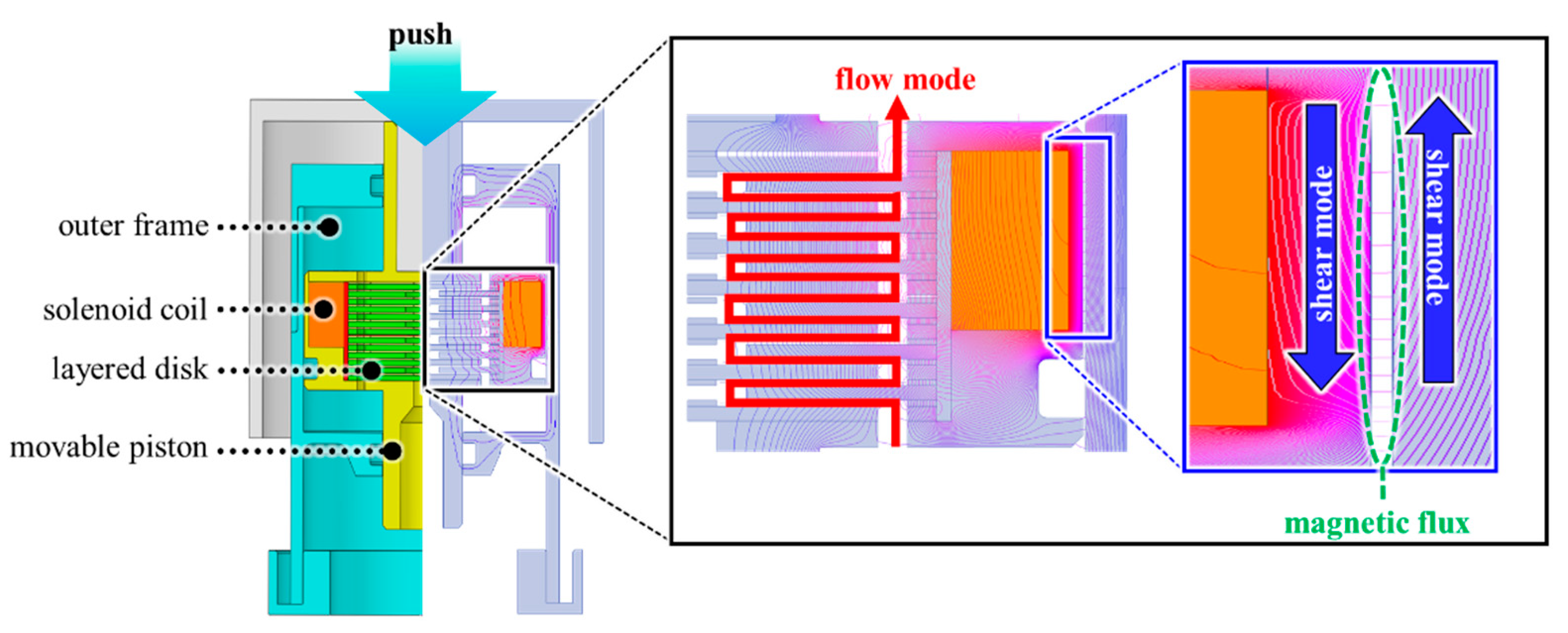
2. Design of an MR Actuator with a Movable Piston
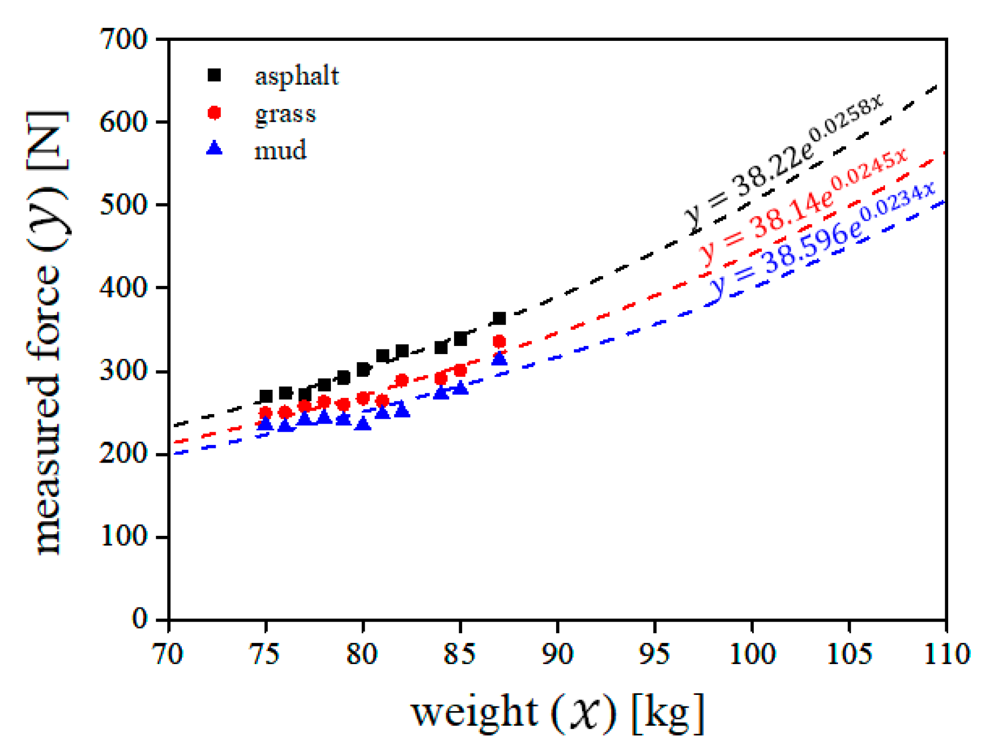
2.1. Preliminary Experiment
It is known that the force that a person receives while walking is concentrated towards the heel, a metatarsophalangeal joint, and toe [17]. Based on this, we attached three force sensors on the insole (at the heel portion, a metatarsophalangeal joint portion, and the toe portion) and measure the forces. After that, we asked the participants to walk on mud, grass, and asphalt. During walking, force data sets, which were obtained from the attached force sensors, were transmitted to a remote personal computer using wireless communication (Bluetooth). Eleven people weighing between 75 kg and 87 kg, participated in this test. All participants were between 23 and 28 years of age (average age: 26 years). To enhance the reliability, this procedure was repeated five times for each ground condition (mud and asphalt). Therefore, the total number of trials was 55 for each ground condition, considering 11 participants. As expected, the force obtained from the heel was the strongest among the three forces (from the heel, the metatarsophalangeal joint, and the toe). Figure 1 shows the results of the maximum resistive forces when subjects walked on the two ground types. As expected, the resistive force on the asphalt was larger than that on the mud. Furthermore, the resistive force was proportional to the user’s weight. We fitted the data into a mathematical model, which represented the relationship between human weight () and resistive force (). From the mathematical model (), if a person weighs 100 kg, the resistive force is expected to be 504 N. By considering the force margin, we set the design goal of our MR actuator as 600 N.
Figure 1.
Result of the measured maximum resistive force.
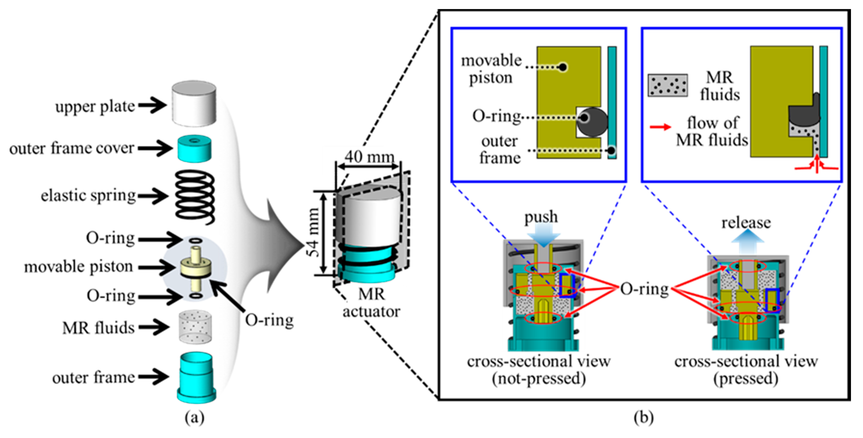
2.2. Structure of the Proposed Actuator
Figure 2a shows a three-dimensional illustration of the proposed MR actuator, composed of an upper plate, an outer frame cover, an elastic spring, a movable piston, MR fluids, and an outer frame. The combination of the outer frame, outer frame cover, and upper plate serves as a magnetic circuit, resulting in a closed-loop magnetic path. A solenoid was embedded into the movable piston. The magnetic flux resulting from the solenoid flows well through the three parts (the outer frame, outer frame cover, and upper plate), minimizing loss. Further, the movable piston was inserted into the outer frame, and MR fluids were poured into the outer frame. We, then, placed the outer frame cover on the outer frame and connected the elastic spring to the outer frame. By connecting the upper plate to the outer frame cover, we completed the fabrication of the proposed MR actuator. If a gap between the movable piston and the outer frame is large, MR fluid does not flow in the flow mode area and remains stationary, and the fluid leaks from the outer frame. To remove the gap, we used O-rings.
Figure 2.
Structure of the proposed MR actuator: (a) Schematic illustration of the proposed MR actuator; (b) Its operating principle.
Figure 2b shows the operating principle of the proposed MR haptic actuator. The pressing force on the upper plate causes the movable piston to move down, causing MR fluids to flow up through a hole in the movable piston. In this process, we can change the hardness of MR fluids by controlling the applied magnetic field. Therefore, the proposed MR actuator creates a variety of haptic sensations.
3. Optimal Design of an MR Actuator with a Movable Piston
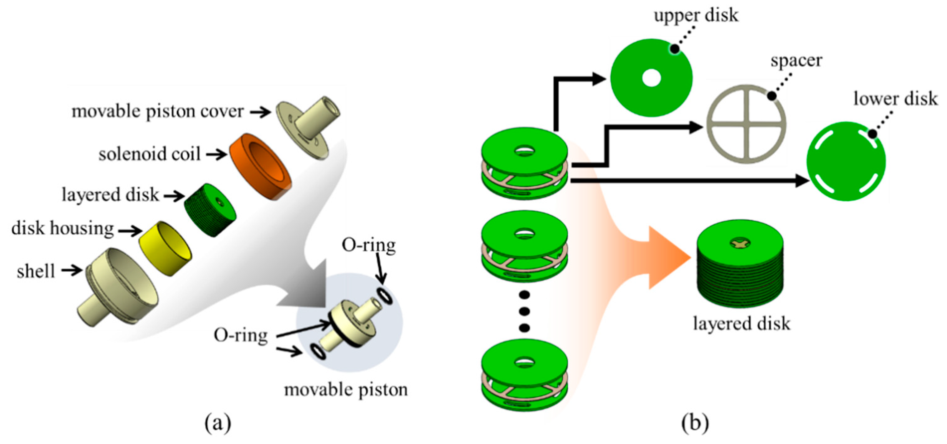
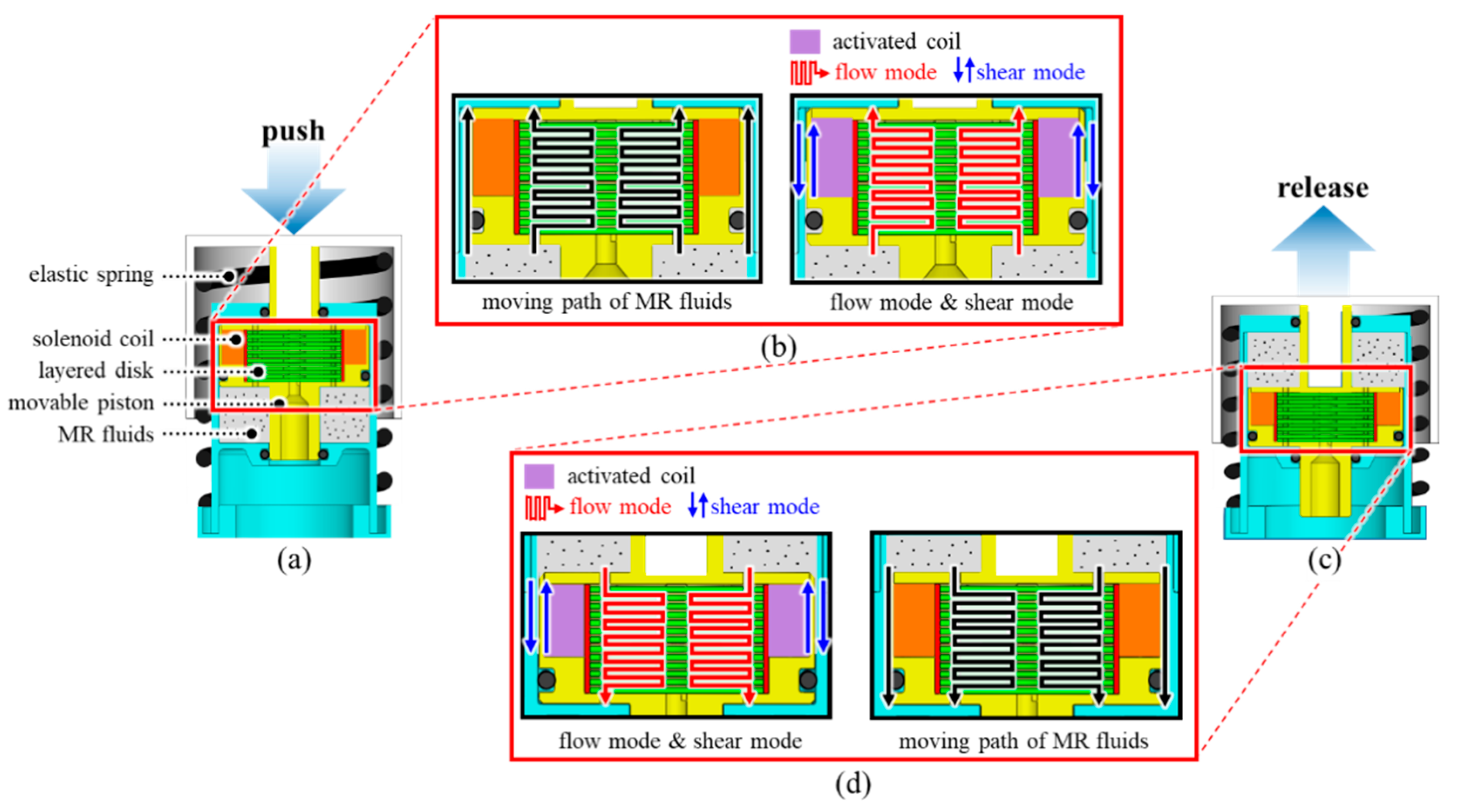
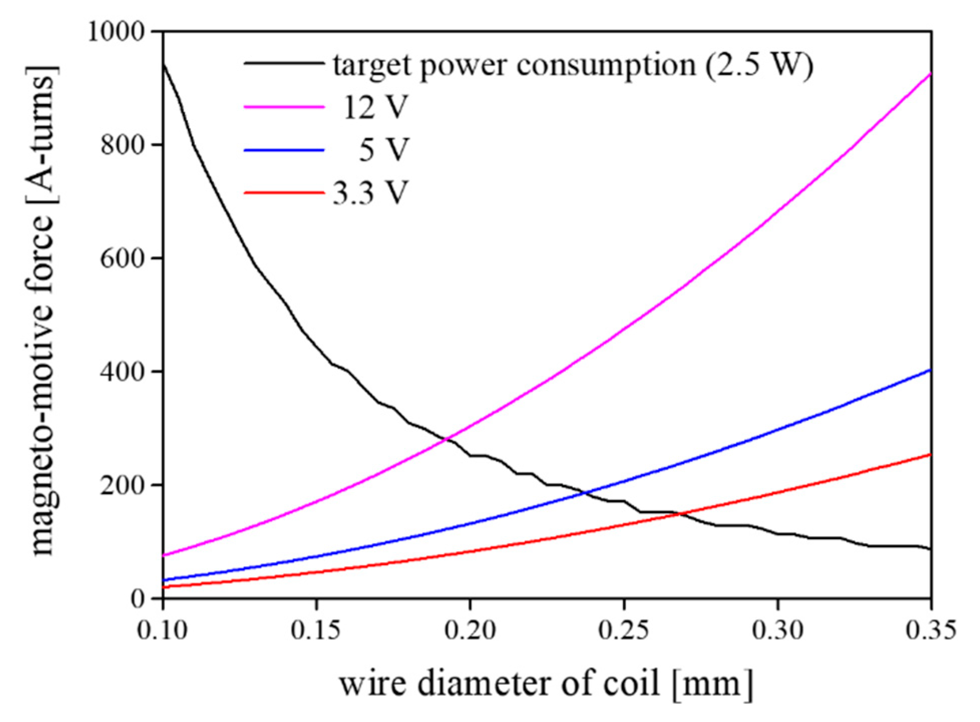
3.1. Optimal Design of the Proposed Actuator
The most important part of our design is the movable piston, which maximizes the resistive force. Furthermore, we present a design of the proposed actuator based on the movable piston, where multiple operation modes of MR fluids contribute to the actuation at the same time. Figure 3a shows the new design of a movable piston consisting of a movable piston cover, a solenoid coil, a layered disk, a disk housing, and a shell. A layered disk is mounted in the disk housing, and it is then placed inside the solenoid coil. Subsequently, the solenoid coil, including the layered disk and disk housing, is embedded into the shell. Finally, by attaching a movable piston cover to the shell, the movable piston is produced. The disk housing was used to prevent the solenoid coil from scratching. Figure 3b shows the structure of the layered disk. Three patterns (an upper disk, a spacer, and a lower disk) are repeated in the layered disk. The upper disk has a hole in its middle part, and the lower disk has four holes in its outer part. The two layers (the upper and lower layers) are made of a structural carbon steel (S45C), and the spacer is fabricated by austenitic stainless steel (stainless steel 304).
Figure 3.
Design of the movable piston: (a) Internal structure; (b) Schematic illustration of the layered disk.
Figure 4 shows the detailed operating principle of the proposed MR haptic actuator. Figure 4a shows the initial state. As previously mentioned, the movable piston is filled with MR fluids, both inside and outside. The force on the upper plate causes the spring to compress, moving the piston downward. This movable piston’s motion allows the MR fluid to flow through holes in the layered disk (Figure 4b). In the case of no voltage input to the solenoid coil, the MR fluid flows well because the MRF is in the fluid state. Therefore, the proposed actuator is softly pressed. Under a magnetic field, the magnetic particles in the MRF form chains, and the MRF become semisolid. This effect disturbs the flow of MR fluids to increase the resistive force during pressing. For this reason, the MR haptic actuator can create various resistive forces depending on the magnetic field. After release, the deformed spring returns to its original configuration, MR fluids flow down via holes in the layered disk (Figure 4d), and the movable piston also returns to its initial position.
Figure 4.
Operating principle and mechanism of the proposed MR actuator: (a) At the resting state (not pressed); (b) Operating principle when push is applied; (c) At the pressed state; (d) Operating principle when push is released.
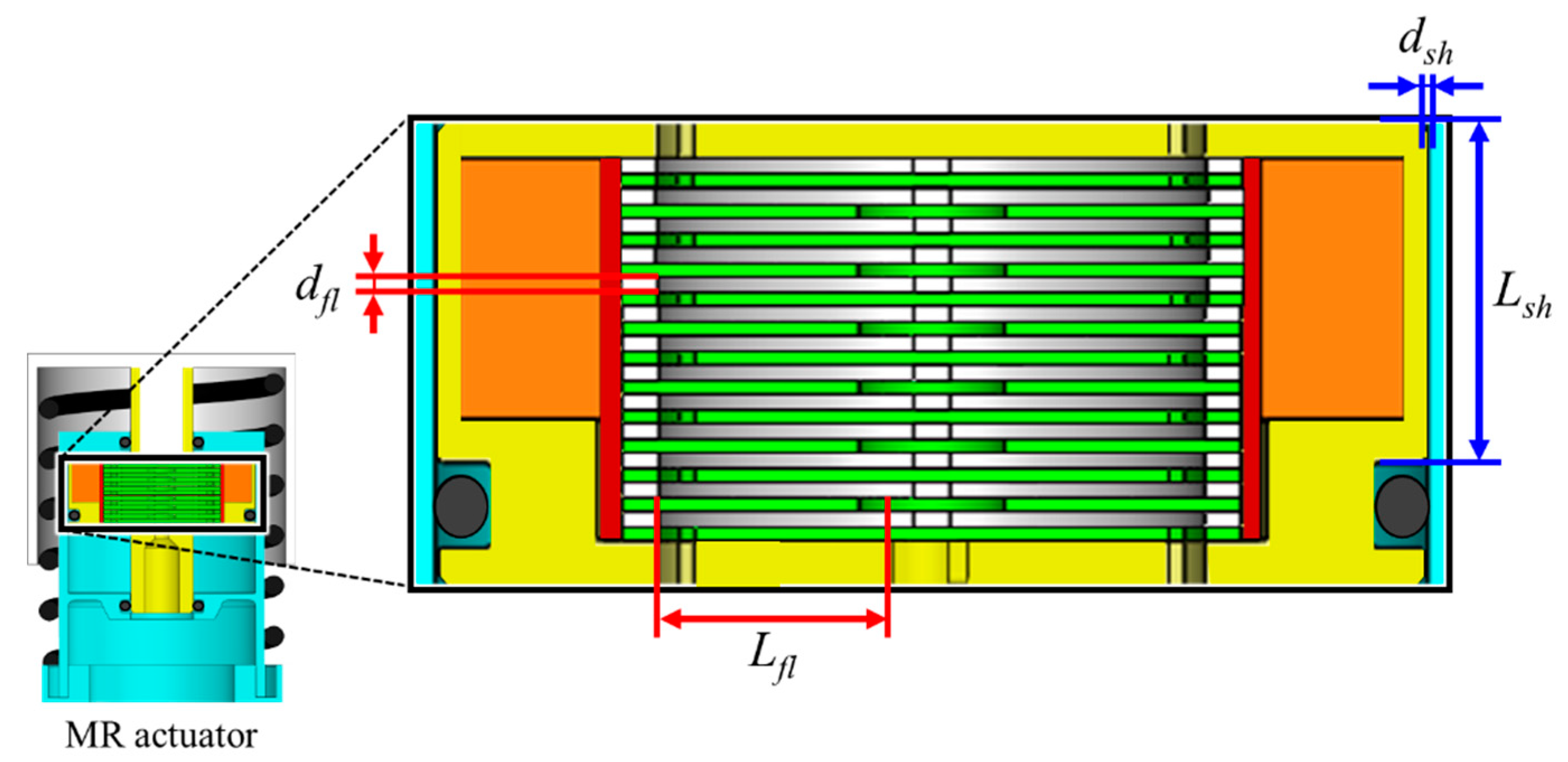
3.2. Simulation of the Proposed Actuator
The design goal of the MR haptic actuator is to maximize its resistive force in the limited size of an actuator by integrating multiple modes (flow mode and shear mode) of MR fluids. A finite element method (FEM) simulation was performed using commercial software (Ansys Maxwell) to investigate whether multiple operation modes of MR fluids contribute to the actuation of the proposed module at the same time. Furthermore, we checked that the magnetic field flows well, forming a close path with minimal magnetic loss. Figure 5 shows the simulation results of the proposed actuator. The simulation results indicate that the magnetic field created by the solenoid coil passes along the movable piston and outer frame, and returns to its original position, resulting in a closed path. This means that there is little magnetic flux leakage in the proposed design, and most of the magnetic field generated by the solenoid coil contributes to haptic actuation. Moreover, we found that the proposed MR actuator was designed to use multiple operation modes (shear and flow modes) of MR fluids so that the resistive force was maximized in a limited size. We confirmed that magnetic flux is perpendicular to the shear direction in the outer peripheral part through Figure 5. When the piston moves downward, the MR fluids flow through the gap between the movable piston and the outer frame, which creates shear stress (shear mode). Furthermore, the MR fluids flow through holes in the layered disk and through the gap between the disk and its neighbor. This flow of the MR fluid generates the yield stress (flow mode). Therefore, as the user pushes the proposed actuator, he/she can perceive the feedback force, which is determined by summing up the shear and yield stresses created by the MR fluids.
Figure 5.
FEM simulation of the proposed design.
The solenoid coil was optimized to increase the resistive force related to the magneto-motive force (Fm) of the solenoid coil. The magneto-motive force (Equation (1)) is proportional to the number of turns (N) of the solenoid coil, input voltage (V), and area (P) of the coil. Furthermore, it is inversely proportional to the resistivity of copper (ρ = 1.72 × 10⁻⁸ Ωm) and the total length (ltotal) of the solenoid coil. Figure 6 shows the simulation results of the magneto-motive force as a function of the wire diameter. In Figure 6, the black line denotes the computed magneto-motive force under fixed power consumption (2.5 W), and the other three colored lines represent the magneto-motive force under fixed input voltages (12 V, 5 V, and 3.3 V). In this work, we chose the wire diameter of the solenoid coil to be 0.24 mm because we considered an input voltage of 5 V:
Figure 6.
Simulation result of the magneto-motive force as a function of wire diameter.
As mentioned before, two operation modes (flow and shear modes) simultaneously contribute to the actuation of the proposed module. The resistive force obtained from the flow mode of the MR fluids is expressed by Equation (2), and the resistive force by the shear mode is described by Equation (3). In Equations (2), and (3), the yield stress (σ), which is proportional to the magnetic intensity (H), was computed by using [18,19,20,21]. Based on these equations, we simulated the resistive force as a function of the input current. The computed resistive force increases from 193 N to 652 N as we increase the input current, as shown in Figure 7,
where
Figure 7.
Simulated resistive force as a function of input current.
- u:
- plastic viscosity (0.28 [Pa·s]),
- Afl:
- area of the layered disk (300.25 [𝛑·mm2]),
- bfl:
- circumference of a disk (11 [𝛑·mm]),
- bsh:
- circumference of the movable piston (27 [𝛑·mm]),
- dfl:
- gap between a disk and its neighbor (0.2 [mm]) (Figure 8),
Figure 8. Variables for computing resistive force. - dsh:
- dsh: gap between the outer frame and the movable piston (0.1 [mm]) (Figure 8),
- Lfl:
- distance that MR fluids flow in the gap (5.5 [mm]) (Figure 8),
- Lsh:
- distance that MR fluids move for shear mode (11.1 [mm]) (Figure 8),
- :
- velocity of movable piston,
- σ:
- yield stress.
4. Fabrication and Result of the Proposed Haptic Actuator
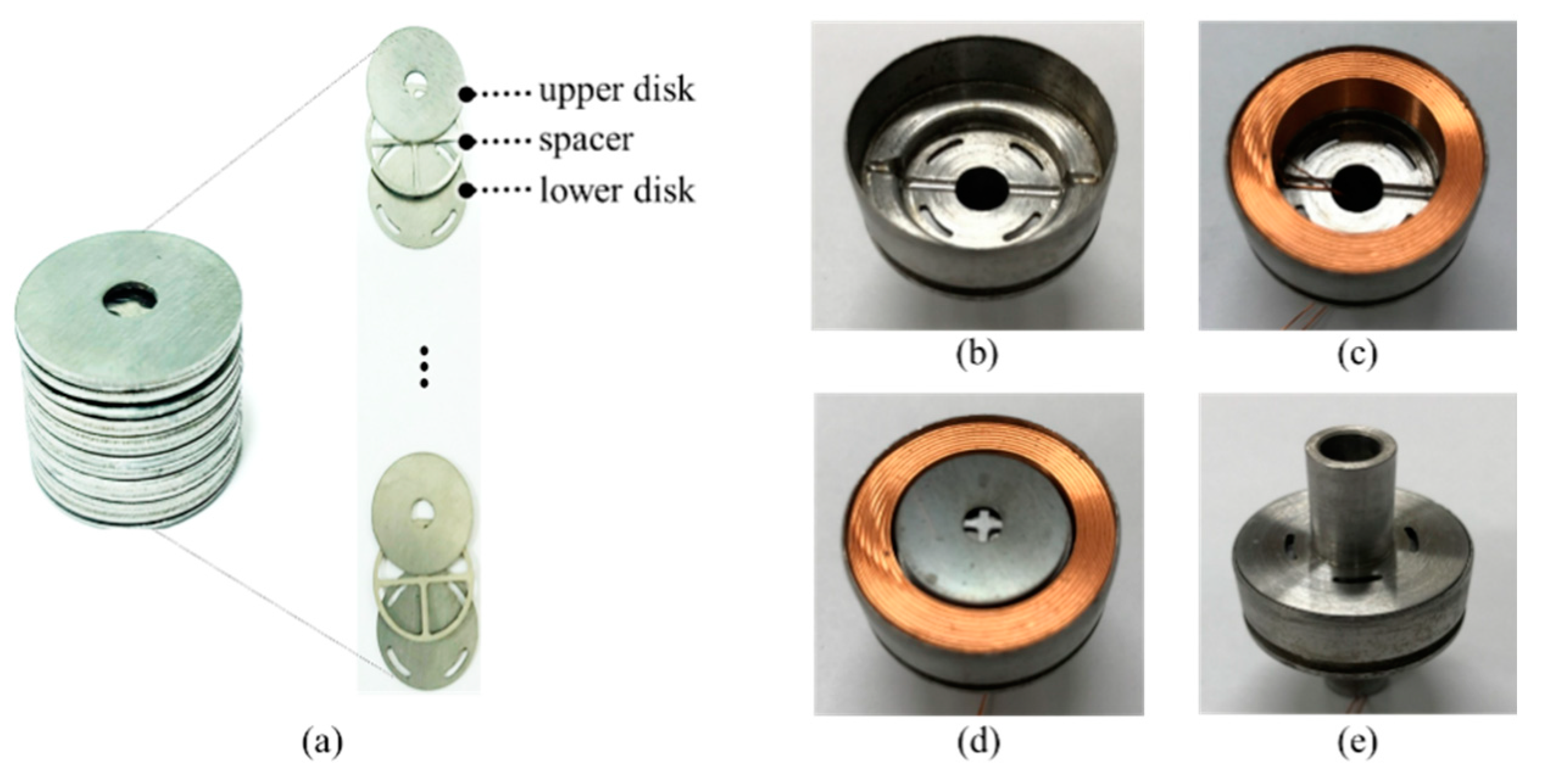
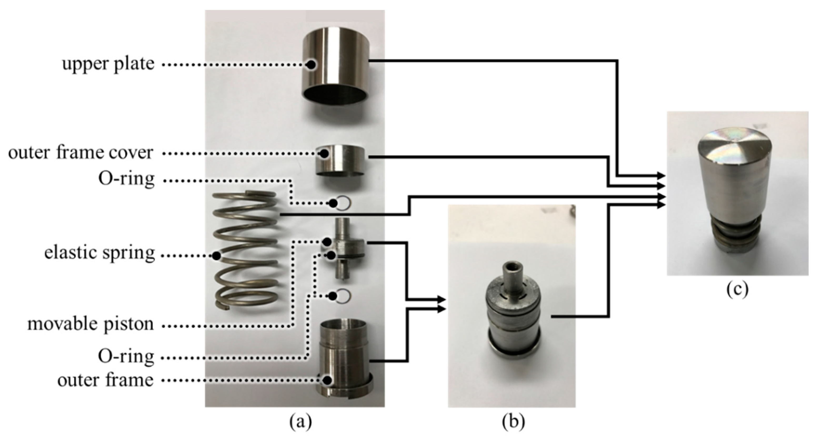
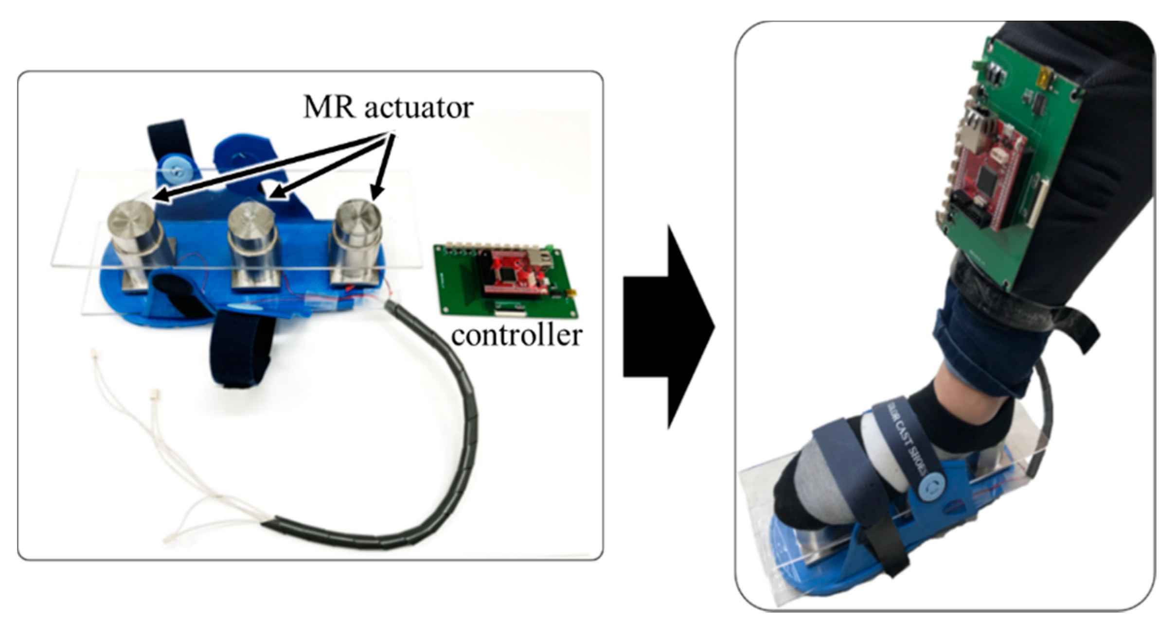
4.1. Fabricated Haptic Actuator
Figure 9 shows the fabrication process of the movable piston consisting of three O-rings, a movable piston cover, a solenoid coil, a layered disk, an outer frame, and a shell. Figure 9a shows the layered disk where three patterns are repeated. We drilled a hole to pull the coil wire out of the movable piston to provide input voltage to the solenoid coil outside the movable piston. (Figure 9b). Then, we fit the solenoid coil in the shell (Figure 9c) and inserted the layered disk into the coil, as shown in Figure 9d. Finally, we could make a movable piston by placing the movable piston cover on the shell (Figure 9e). Figure 10 shows the fabrication process of the MR haptic actuator, which is composed of a spring, an upper plate, an outer frame cover, a movable piston, and an outer frame. One end of the movable piston is connected to the outer frame, as shown in Figure 10b. After placing the spring around the outer frame, the other end of the movable piston is fitted into the upper plate through a hole in the outer frame cover (Figure 10c).
Figure 9.
Fabrication process of the movable piston: (a) The layered disk where three patterns are repeated; (b) Shell; (c) Solenoid coil fitted in the shell; (d) Layered disk inserted into the shell; (e) Fabricated movable piston.
Figure 10.
Fabrication process of the proposed MR haptic actuator: (a) Exploded view of the proposed MR haptic actuator; (b) Combined movable piston with outer frame; (c) Fabricated MR haptic actuator.
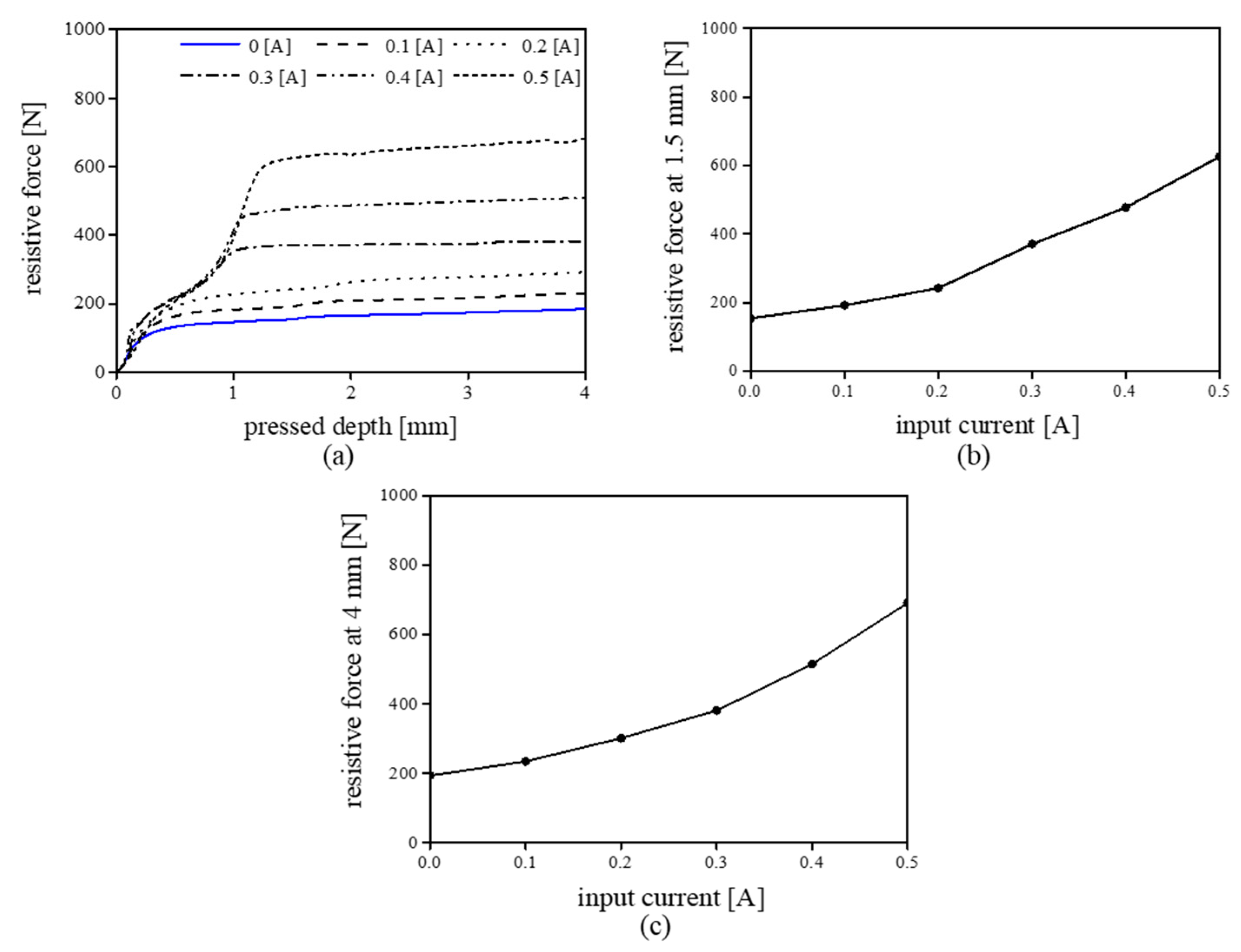
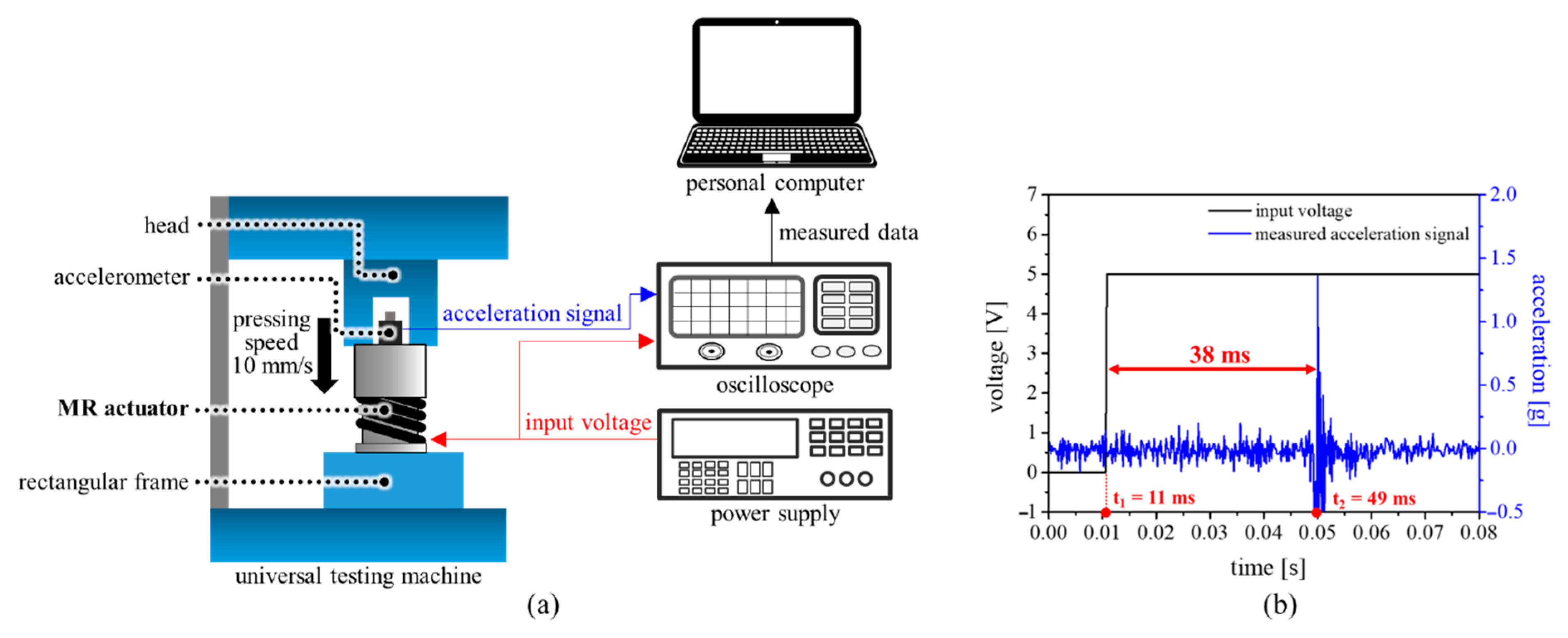
4.2. Experimental Result
Figure 11 shows an experimental system that consists of a personal computer (PC), a power supply, and a universal testing machine (UTM, H5KT, Titus, Olsen), including a load cell. The proposed haptic actuator was attached on the upper surface of the rigid rectangular frame, which was bolted to the UTM. The measurement head was moved along the vertical (z-axis) direction (with a constant speed of 1 mm/s) to push down the proposed haptic actuator. The speed of the measurement head and the resistive force obtained from the load cell were conveyed to the PC. During this experiment, the resistive force was measured by changing the input current (from 0 A to 0.5 A) and measurement head position (from 0 mm to 4 mm).
Figure 11.
Experimental environment for measuring the haptic performance of a proposed actuator.
Figure 12a shows the measured resistive force as a function of the proposed actuator’s stroke (head position). As previously mentioned, we changed the input current from 0 A to 0.5 A at 0.1 A interval. Under no current, the resistive force of the proposed MR actuator was 154 N at a 1.5 mm stroke. The resistive force increased to approximately 625 N at 1.5 mm stroke when we provided an input current of 0.5 A. Therefore, the resistive force of the proposed MR actuator can be controlled by changing the input current. For all input currents, the resistive force increases until the stroke reaches approximately 1 mm, and then it becomes saturated. As previously mentioned, just noticeable difference (JND) of the human foot is approximately 30–50% [22]. If JND is assumed to be 40%, the user can sense over five steps of the magnitude of the haptic force.
Figure 12.
Experimental result of the proposed actuator: (a) Measured resistive force as a function of the proposed actuator’s stroke (head position); (b) Measured resistive force at 1.5 mm stroke; (c) Measured resistive force at 4 mm stroke.
We used the same UTM as the previous one, and put an accelerator instead of the load cell (Figure 13a). The measurement head was moved along the vertical axis to push down the proposed actuator without applying current. During pushing, the applied input voltage at a moment makes the MR fluids rigid. At this time, MR fluid changes its state from liquid to solid, resulting in vibration. Figure 13b shows the measured response time of the proposed MR haptic actuator when we provide step input voltage to the proposed MR actuator. In Figure 13b, the solid black line is the applied input voltage and the solid blue line is the measured vibration when the step input is applied to the proposed MR actuator. The response time (38 ms) was computed by subtracting t1 (at the voltage is applied) from t2 (at vibration occurs). From the results, the proposed MR actuator can be useful for haptically simulating ground shape/compliance in virtual environment.
Figure 13.
(a) Experimental environment and (b) the measured response time of the proposed actuator.
5. Conclusions
We presented a haptic actuator based on MR fluids for haptic shoes. Furthermore, we optimized the structure of the haptic actuator to integrate multiple operation modes (flow and shear modes) of MR fluids. The simulation using the finite element method (FEM) confirmed that multiple operation modes of MR fluids contribute to the haptic actuation in the proposed module. Additionally, we observed that the magnetic field flows well, forming a close path with minimal magnetic loss. The measured resistive force varied from 154 N to 625 N at the stroke of 1.5 mm as the input current was changed from 0 to 0.5 A. The experimental results show that the proposed MR actuator can be used in an interface device for haptically simulating ground in a virtual environment. It is known that the resistive force in running becomes stronger than in walking. Therefore, we are improving the proposed MR haptic actuator to haptically simulate not only walking but also running on the ground. Furthermore, we are currently fabricating a haptic shoe using the three proposed MR actuators (Figure 14) and we are currently studying a haptic rendering method for haptically expressing virtual ground using the proposed MR haptic actuator.
Figure 14.
Three MR haptic actuators which are installed to the shoe.
Author Contributions
Y.H.H. designed the research problems; S.B. conducted the data curation and visualization; T.-H.K. and I.-H.Y. conducted experiments and analyzed the results; J.R.K. suggested the idea and configuration of the structure of the paper; S.-Y.K. supervised the research. All authors discussed the results and wrote the paper. All authors have read and agreed to the published version of the manuscript.
Funding
This work was supported by the Priority Research Centers Program through the National Research Foundation of Korea (NRF), funded by the Ministry of Education (NRF-2018R1A6A1A03025526). This work was also supported by the National Research Foundation of Korea (NRF) grant funded by the Korean government (MSIT) (NRF-2020R1I1A3065371).
Institutional Review Board Statement
Not applicable.
Informed Consent Statement
Not applicable.
Data Availability Statement
Data is contained within this manuscript.
Acknowledgments
We thank the Cooperative Equipment Center at Koreatech for assistance with the Universal Testing Machine (UTM) experiment.
Conflicts of Interest
The authors declare no conflict of interest.
References
- Serafin, S.; Turchet, L.; Nordahl, R.; Dimitrov, S.; Berrezag, A.; Hayward, V. Identification of Virtual Grounds using Virtual Reality Haptic Shoes and Sound Synthesis. In Proceedings of the Eurohaptics Symposium on Haptic and Audio-Visual Stimuli: Enhancing Experiences and Interaction, Amsterdam, The Netherlands, 7 July 2010. [Google Scholar]
- Takeuchi, Y. Gilded gait. In Proceedings of the 23nd Annual ACM Symposium on User Interface Software and Technology-UIST ’10, New York, NY, USA, 3–6 October 2010. [Google Scholar] [CrossRef]
- Magana, M.; Velázquez, R. On-shoe tactile display. In Proceedings of the 2008 IEEE International Workshop on Haptic Audio Visual Environments and Games, Ottawa, ON, Canada, 18–19 October 2008; pp. 114–119. [Google Scholar]
- Yokota, T.; Ohtake, M.; Nishimura, Y.; Yui, T.; Uchikura, R.; Hashida, T. Snow walking. In Proceedings of the 6th Augmented Human International Conference on AH ’15, Singapore, 9–11 March 2015; Association for Computing Machinery (ACM): New York, NY, USA, 2015; pp. 45–48. [Google Scholar]
- Iwata, H.; Yano, H.; Tomiyoshi, M. String Walker. In Proceedings of the ACM SIGGRAPH 2007 Emerging Technologies, San Diego, CA, USA, 13 August 2007. [Google Scholar]
- Jirattigalachote, W.; Shull, P.B.; Cutkosky, M.R. Virtual pebble: A haptic state display for pedestrians. In Proceedings of the 2011 RO-MAN, Atlanta, GA, USA, 31 July–3 August 2011; Institute of Electrical and Electronics Engineers (IEEE): New York, NY, USA, 2011; pp. 401–406. [Google Scholar]
- Schmidt, D.; Kovacs, R.; Mehta, V.; Umapathi, U.; Köhler, S.; Cheng, L.-P.; Baudisch, P. Level-Ups. In Proceedings of the 33rd Annual ACM Conference on Human Factors in Computing Systems-CHI ’15, Seoul, Korea, 18–23 April 2015; Association for Computing Machinery (ACM): Beijing, China, 2015. [Google Scholar]
- Horodniczy, D.; Cooperstock, J.R. Free the Hands! Enhanced Target Selection via a Variable-Friction Shoe. In Proceedings of the 2017 CHI Conference on Human Factors in Computing Systems, New York, NY, USA, 16 July 2017; Association for Computing Machinery: New York, NY, USA, 2017; pp. 255–259. [Google Scholar]
- Shokrollahi, E.; Goldenberg, A.A.; Drake, J.M.; Eastwood, K.W.; Kang, M. Application of a Nonlinear Hammerstein-Wiener Estimator in the Development and Control of a Magnetorheological Fluid Haptic Device for Robotic Bone Biopsy. Actuators 2018, 7, 83. [Google Scholar] [CrossRef]
- Chen, D.; Song, A.; Tian, L.; Yu, Y.; Zhu, L. MH-Pen: A Pen-type Multi-mode Haptic Interface for Touch Screens Interaction. IEEE Trans. Haptics 2018, 11, 1. [Google Scholar] [CrossRef] [PubMed]
- Kavas, O.; Gurocak, H. Haptic Interface with Linear Magnetorheological (MR) Brakes for Drone Control. In Proceedings of the 2018 15th International Conference on Ubiquitous Robots (UR), New York, NY, USA, 25 May 2018; Institute of Electrical and Electronics Engineers: New York, NY, USA, 2018; pp. 676–681. [Google Scholar]
- Guo, S.; Song, Y.; Yin, X.; Zhang, L.; Tamiya, T.; Hirata, H.; Ishihara, H. A Novel Robot-Assisted Endovascular Catheterization System with Haptic Force Feedback. IEEE Trans. Robot. 2019, 35, 685–696. [Google Scholar] [CrossRef]
- Nguyen, H.Q.; Le, T.D.; Nguyen, D.N.; Le, T.D.; Lang, T.V.; Ngo, T.V. Development of 3-DOF Force Feedback System Using Spherical Arm Mechanism and MR Brakes. Int. J. Mech. Eng. Robot. Res. 2020, 9, 170–176. [Google Scholar] [CrossRef]
- Son, H.; Gil, H.; Byeon, S.; Kim, S.-Y.; Kim, J.R. RealWalk. In Proceedings of the Extended Abstracts of the 2018 CHI Conference on Human Factors in Computing Systems, New York, NY, USA, 13 March 2018; Association for Computing Machinery: New York, NY, USA, 2018; p. D400. [Google Scholar]
- Son, H.; Hwang, I.; Yang, T.-H.; Choi, S.; Kim, S.-Y.; Kim, J.R. RealWalk: Haptic Shoes Using Actuated MR Fluid for Walking in VR. In Proceedings of the 2019 IEEE World Haptics Conference, New York, NY, USA, 24 February 2019; Institute of Electrical and Electronics Engineers (IEEE): New York, NY, USA, 2019; pp. 241–246. [Google Scholar]
- Yang, T.-H.; Son, H.; Byeon, S.; Gil, H.; Hwang, I.; Jo, G.; Choi, S.; Kim, S.-Y.; Kim, J.R. Magnetorheological Fluid Haptic Shoes for Walking in VR. IEEE Trans. Haptics 2020, 1. [Google Scholar] [CrossRef] [PubMed]
- Koller, U.; Willegger, M.; Windhager, R.; Wanivenhaus, A.; Trnka, H.-J.; Schuh, R. Plantar pressure characteristics in hallux valgus feet. J. Orthop. Res. 2014, 32, 1688–1693. [Google Scholar] [CrossRef] [PubMed]
- Ryu, S. A Sensor-Combined Miniature KinaesTactile Actuator Based on Magnetorheological Fluids. Master’s Thesis, KAIST, Daejeon, Korea, 4 December 2012. [Google Scholar]
- Varela-Jiménez, L.M.; Luna, J.L.V.; Cortés-Ramírez, J.A.; Song, G. Constitutive model for shear yield stress of magnetorheological fluid based on the concept of state transition. Smart Mater. Struct. 2015, 24. [Google Scholar] [CrossRef]
- Wereley, N.M.; Pang, L. Nondimensional analysis of semi-active electrorheological and magnetorheological dampers using approximate parallel plate models. Smart Mater. Struct. 1998, 7, 732–743. [Google Scholar] [CrossRef]
- Lindler, J.; Wereley, N.M. Analysis and Testing of Electrorheological Bypass Dampers. J. Intell. Mater. Syst. Struct. 1999, 10, 363–376. [Google Scholar] [CrossRef]
- Abbink, D.A.; Van Der Helm, F.C.T. Force perception measurements at the foot. In Proceedings of the 2004 IEEE International Conference on Systems, Man and Cybernetics (IEEE Cat. No.04CH37583), The Hague, The Netherlands, 10–13 October 2004; Institute of Electrical and Electronics Engineers (IEEE): New York, NY, USA, 2005. [Google Scholar]
Publisher’s Note: MDPI stays neutral with regard to jurisdictional claims in published maps and institutional affiliations. |
© 2020 by the authors. Licensee MDPI, Basel, Switzerland. This article is an open access article distributed under the terms and conditions of the Creative Commons Attribution (CC BY) license (http://creativecommons.org/licenses/by/4.0/).