Article

Repair of Heavily Damaged RC Beams Failing in Shear Using U-Shaped Mortar Jackets

by
Constantin E. Chalioris
1,*,
Violetta K. Kytinou
1,
Maristella E. Voutetaki
2 and
Nikos A. Papadopoulos
1
1
Reinforced Concrete and Seismic Design of Structures Laboratory, Civil Engineering Department, School of Engineering, Democritus University of Thrace, 67100 Xanthi, Greece
2
Structural Science and Technology Division, Architectural Engineering Department, School of Engineering, Democritus University of Thrace, 67100 Xanthi, Greece
*
Author to whom correspondence should be addressed.
Buildings 2019, 9(6), 146; https://doi.org/10.3390/buildings9060146
Submission received: 4 June 2019 / Revised: 12 June 2019 / Accepted: 13 June 2019 / Published: 14 June 2019

Abstract

:
The effectiveness of slightly reinforced thin U-shaped cementitious mortar jacketing for the repair of damaged shear-critical reinforced concrete beams is experimentally investigated. The test project includes two parts. In the first one, five concrete beams over-reinforced against flexure and under-reinforced against shear with different ratio of closed stirrups were initially subjected to monotonic loading until failure. The initially tested beams have been designed to fail in shear after wide diagonal cracking and to exhibit various strength and deformation capacities along with different levels of damages. In the second experimental part, the heavily damaged beams were jacketed with mild steel small diameter U-shaped transverse stirrups and longitudinal reinforcing bars. The retrofitted specimens using the proposed jacketing technique were tested again following the same four-point-bending load scheme. Based on the overall performance of the beams, it is deduced that the shear strength and deformation capability of the jacketed beams were substantially increased compared to the corresponding capacities of the initial beams. Further, although all beams failed in a shear abrupt manner, the retrofitted ones exhibited reduced brittleness and higher deflections at failure up to six times with respect to the initially tested specimens. The level of the initial damage influences the efficiency of the jacketing. Additional test data derived from relative shear-damaged beam specimens and retrofitted with similar thin jackets is also presented herein in order to establish the effectiveness of this repair system and to clarify the parameters affecting its structural reliability. Comparisons indicated that jacketed beams can alter the failure mode from brittle shear to ductile flexural under certain circumstances.

1. Introduction

A considerable amount of existing reinforced concrete (RC) buildings that were designed based on old code provisions and, in many cases, only for gravity loads can be found worldwide. These buildings have usually under-reinforced members against shear, which are vulnerable to brittle failure as their strength and deformation ability is limited [1,2,3]. Further, typical constructional details of transverse reinforcement in old RC buildings include low strength, small diameter, open and wide spacing stirrups or hoops with 90-degree bends. Furthermore, the first strengthening attempts in RC frame structures with long spans and increased bending moment demands were mainly focused on the enhancement of their flexural capacity [4,5]. This way, existing stirrups are not proportioned to prevent lap or shear failures. Thus, shear retrofit is deemed necessary in order to eliminate the propensity for shear-critical members, which is derived from the above considerations.
A popular retrofitting technique for deficient RC members of existing structural systems is RC jacketing. Several investigations have reported the merits of traditional RC jackets for increasing load bearing capacity and stiffness, and efficiently improving the overall structural performance [6,7,8,9]. However, apparent shortcomings of thick and heavily reinforced jackets constructed with common cast-in-place concrete caused this retrofitting method to lose ground [10,11,12]. These disadvantages are mainly related to labor-intensive and time-consuming procedures, the reduction of the available floor-space, and the significant mass and stiffness increase, which subsequently modify the dynamic characteristics of the structural system [13,14,15,16].
These reasons have led researchers to switch to new jacketing techniques with alternative materials such as steel [17,18,19], advanced materials such as fiber reinforced polymer (FRP) [20,21,22,23,24,25], textile reinforced concrete or mortar [26,27,28,29] and shape memory alloys [30,31,32], cement-based materials such as ferrocement [33,34,35,36], steel fibrous concrete or mortar [37,38,39,40], high-performance fiber reinforced concrete [41,42,43,44,45,46,47,48], self-compacting concrete (SCC) [49,50,51,52,53,54], and thin slightly reinforced flowable mortar [55,56]. Many of these jacketing techniques have been proved successful substitutes to common RC jacketing. However, most of these studies investigate jackets as strengthening technique applied to undamaged RC members and only some of them [20,23,25,29,35,37,46,47,51,52,53,54,55] examine jacketing as a method to repair already damaged RC members, as stated and discussed below.

1.1. Jacketing as a Repair Technique in Damaged RC Structural Members

Karayannis and Sirkelis [20] performed an experimental project of large-scaled beam-column joint specimens subjected to cyclic deformations. Some specimens have initially been strengthened by full-wrapped jackets from epoxy-bonded carbon FRP sheets in the joint area, the columns, or/and the beam critical region. Other specimens have previously been damaged by the imposed cyclic loading and repaired using epoxy resin injections and FRP jackets with different configurations. It was found that the combination of the proposed techniques significantly enhanced the capacity, the energy absorption, the ductility, and the type of the failure mode. Tsonos [23] also experimentally investigated the effectiveness of RC and FRP jacketing in external beam-column joint specimens as postearthquake and pre-earthquake retrofitting. Undamaged or shear-damaged joint specimens under initial lateral cyclic loading have successfully been strengthened or rehabilitated, respectively, using high-strength mortar jackets reinforced with meticulous reinforcement arrangements or by FRP jackets with various configurations in the joint area. Results have demonstrated the merits and the shortcomings of both jacketing techniques as strengthening or repair methods.
Nguyen-Minh and Rovnak [25] examined the shear response of original (uncracked) or precracked RC beams that have been strengthened or repaired, respectively, using U-shaped jackets made of epoxy-bonded glass or carbon FRP sheets. Test results indicated that the initial damage influenced the overall response of the jacketed beams. Although all beams, strengthened and repaired, failed in shear, the repaired ones exhibited reduced brittleness of the shear failure, tensile strains in stirrups and crack width with regard to the initially tested specimens.
Contamine et al. [29] conducted tests on RC beams that have been designed to fail in shear. Examined beams were first damaged by a four-point loading test until a specific yield strain (2.7%) of one steel stirrup and then repaired by textile reinforced concrete jackets or by carbon FRP sheets. Various jacketing configurations have been examined and although the failure mode of most of the repaired specimens has not been altered (nine of the 11 jacketed beams failed in shear, as did the initial ones), the proposed method has been successful for the retrofit of shear-damaged RC beams since all rehabilitated beams exhibited increased strength and improved overall response.
Bansal et al. [35] applied low cost U-shaped ferrocement jackets in slightly damaged flexural RC beams that have initially been loaded up to 75% of their safe load carrying capacity, corresponding to the allowable deflection span/250. The efficiency and the cost of the proposed ferrocement jackets with various wire mesh orientation have been reported. The repaired specimens exhibited improved cracking and deflection performance along with increased ductility and energy absorption.
Martinola et al. [37] studied the effectiveness of a 40 mm thick U-shaped jacket made of a high-performance fibrous mortar that has been reinforced with short steel fibers. This jacket has been applied for the strengthening of a plain concrete and an RC beam as well as for the repair of a damaged RC beam that had initially sustained flexural imposed loading until yielding of the tension longitudinal bars. In both cases, the examined jacketing provided an efficient structural enhancement of deficient and damaged RC members at the ultimate and serviceability limit states.
Murthy et al. [46] and Hou et al. [47] investigated the effectiveness of a thin layer made of ultra-high-performance cementitious composite with fibers that was applied on the tension face of flexural predamaged and corroded RC beams, respectively. Test results indicated that a rather thin jacketing was adequate to restore the flexural performance of damaged beams that have been preloaded to approximately 90% of the failure load, or steel rebar corroded without debonding.
Dubey and Kumar [51] and Achillopoulou and Karabinis [57,58,59] experimentally investigated the repair of RC column specimens using SCC and traditional RC jackets, respectively. SCC jackets with welded wire mesh have been applied in damaged columns that have initially been loaded up to 80–85% of the theoretical load bearing capacity. RC jackets have been applied in damaged columns due to poor consolidation as constructional damages or due to axial compression preloading that caused severe concrete cracking and spalling. Test results of these studies highlighted the efficiency of the traditional RC and the advanced SCC jackets in terms of ultimate load bearing capacity.
Thin reinforced jackets constructed with premix cement-based flowable mortar were proposed by Karayannis et al. [55] for the rehabilitation of damaged RC beam–column joints. Joint subassemblages have been constructed, tested under cyclic loading, retrofitted, and retested in the same loading sequence. The thickness of these jackets was only 20 mm and the reinforcements installed consisted of 5.5 mm mild steel bars and closed stirrups. Light and dense jacketing reinforcement configurations have been applied depending on the level of damage of the original specimens. A similar jacketing technique has also been addressed by Chalioris et al. [52,53,54] for the rehabilitation of shear or flexural damaged beams. These U-shaped 25 mm jackets were made of flowable small-sized high-strength SCC-reinforced aggregate with 5 mm mild steel bars and U-shaped open stirrups. Promising results have been obtained concerning the reliability, applicability, and efficiency of this retrofitted scheme since the repaired beam–column joint specimens [55] and the beams [52,53,54] demonstrated improved overall performance and, in many cases, ameliorated the failure mode compared to the brittle failure of the initially tested specimens.

1.2. Research Significance

The aforementioned literature review reveals that the majority of the conducted research is focused on the application of nonconventional jackets in strengthening methods of original RC structural members [17,18,19,21,22,24,26,27,28,30,31,32,33,34,36,38,39,40,41,42,43,44,45,48,49,50,56]. Significantly fewer studies investigate such jackets for the repair of preloaded and slightly damaged RC specimens [20,23,25,29,35,37,46,47,51,52,53,54,55]. Further, very few studies (only five from 40) examine the jacketing retrofit of heavily damaged beams failed in shear [25,29,52,53,54]. Besides, although there are some widely accepted considerations concerning the efficiency of jacketing to regain strength and to improve the overall performance, there are still several issues that require further investigation. The contribution of U-shaped and fine-reinforced mortar jackets to the shear capacity of shear-damaged beams and their ability to alter the failure mode of the jacketed structural member from shear to flexure are some examples of research gaps. Furthermore, the increased interest in the use of easy-to-apply jackets with nonconventional reinforcement and advanced materials in retrofitting applications of shear-damaged RC members and the lack of relevant experimental studies are the main motives behind this work.
In this research, the effectiveness of U-shaped jackets made of cementitious mortar and reinforced with small diameter mild steel bars and U-shaped open stirrups for the repair of shear-damaged RC beams is experimentally investigated. Five shear-critical beams with different ratios of stirrups were initially tested and heavily damaged by imposing loading that caused wide diagonal cracks, abrupt reduction of the load bearing capacity, and brittle shear failure. Then, the severely damaged specimens were retrofitted and retested with the same loading scheme.

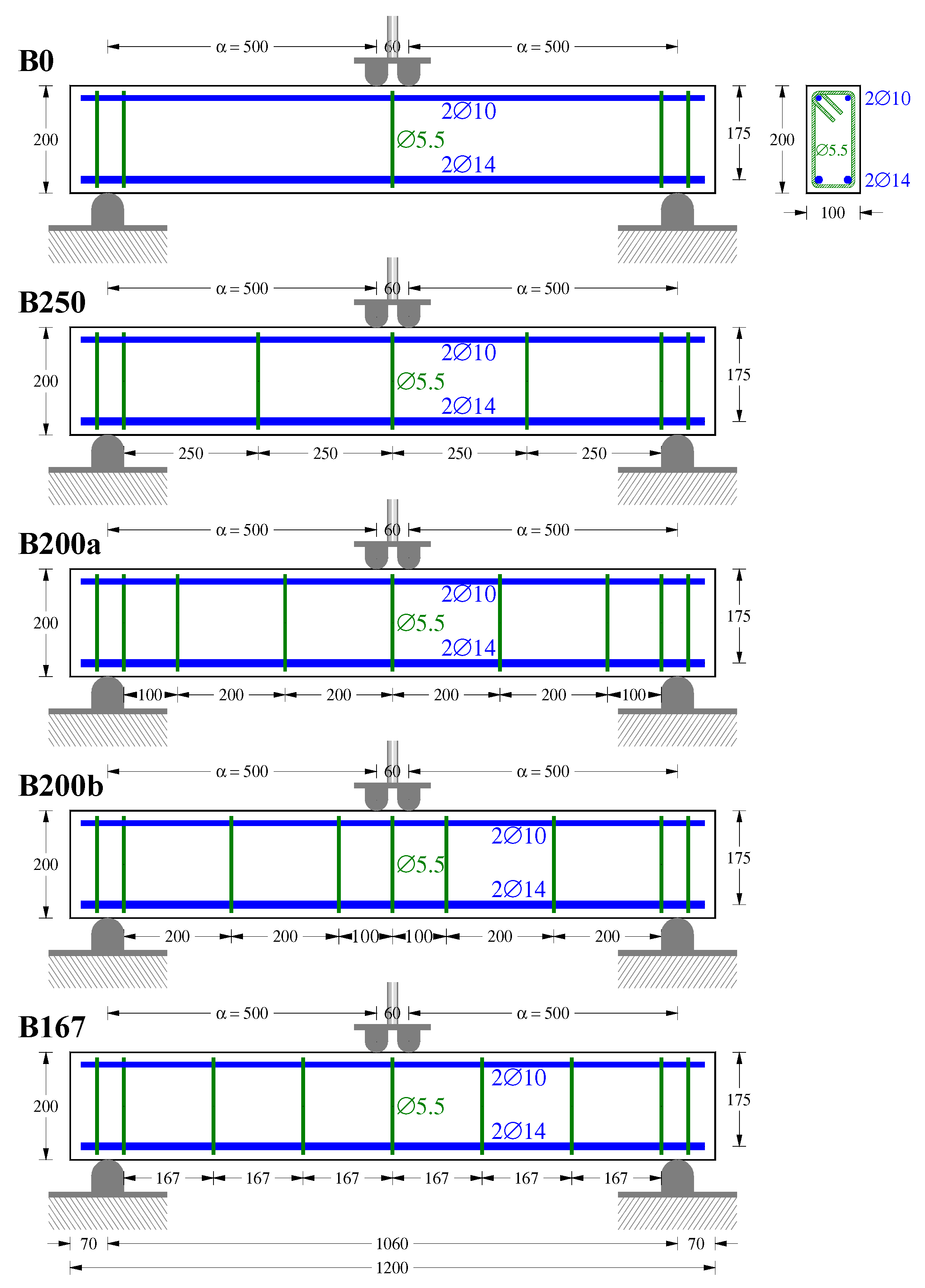
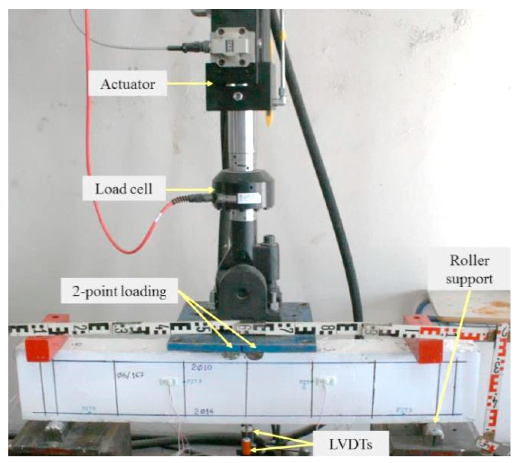
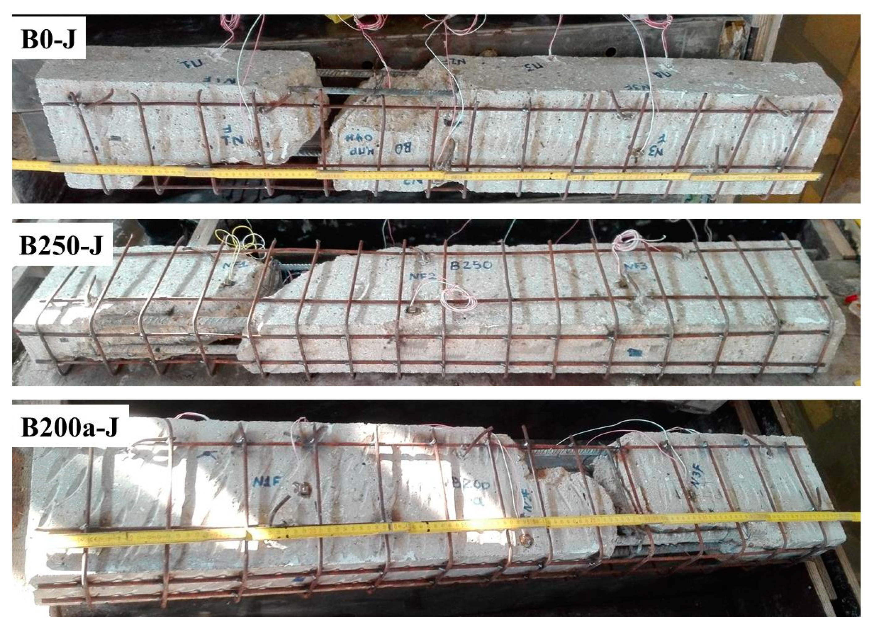
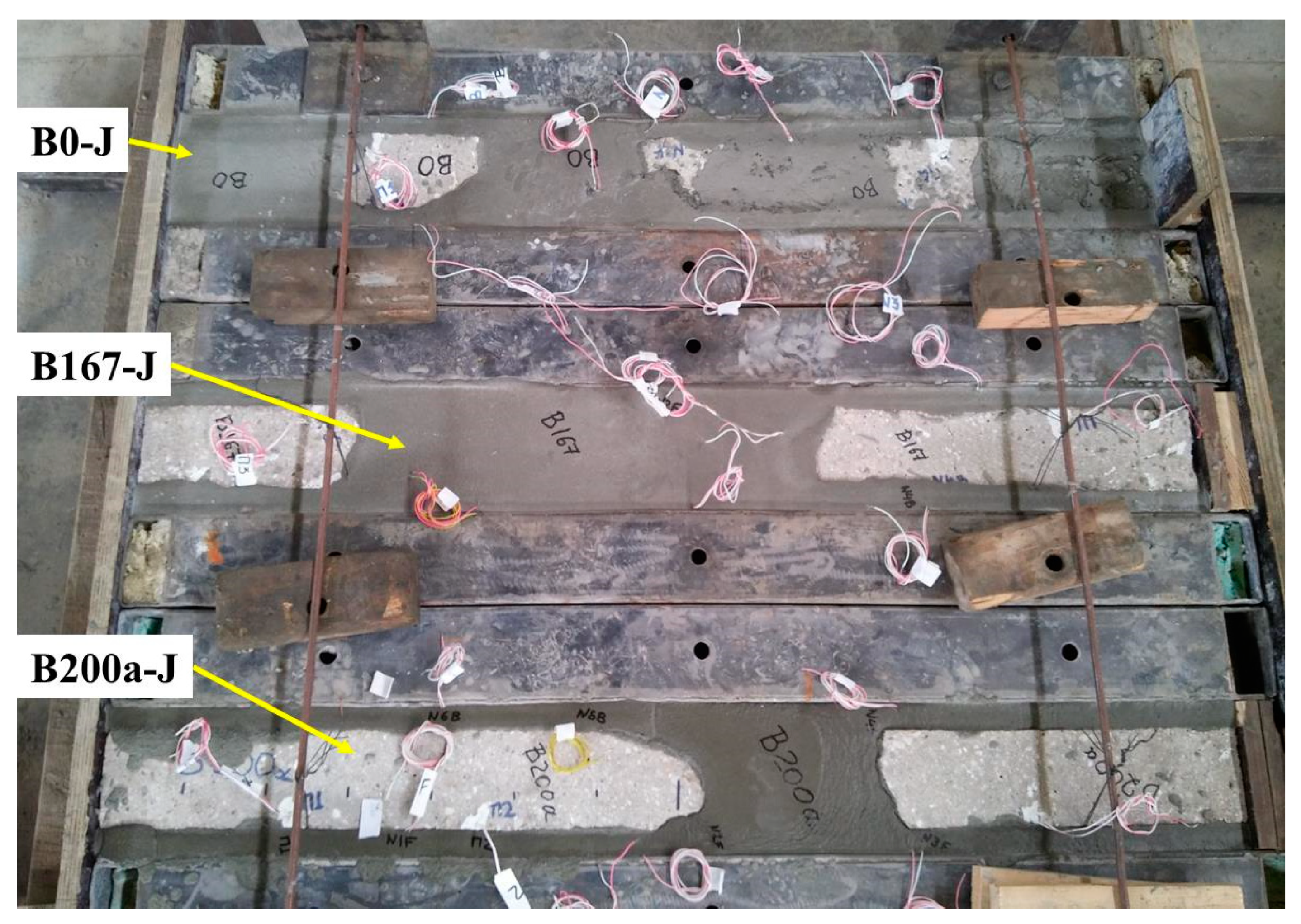
2. Experimental Program of the Initially Tested Shear-Critical Beams

The first part of the conducted test project includes five RC beam specimens 1.2 m long with rectangular cross-section subjected to four-point monotonic loading. The beam characteristics are; width to height ratio b/h = 100/200 mm, effective depth d = 175 mm, shear span α = 500 mm, and shear span-to-depth ratio α/d = 2.86, as presented in Figure 1.
All initially tested beams have the same longitudinal reinforcement; two tension deformed steel bars of diameter 14 mm (2∅14 bottom bars) with yield tensile strength fyl = 550 MPa and two compression deformed steel bars of diameter 10 mm (2∅10 top bars). The beam with the codified name “B0” has no transverse shear reinforcement within the shear span. The other specimens have mild steel closed stirrups of diameter 5.5 mm with yield tensile strength fyv = 225 MPa spacing at 250 mm in beam “B250”, 200 mm in beams “B200a” and “B200b”, and 167 mm in beam “B167” (see also Figure 1). The geometrical and the mechanical reinforcement ratios of the tension longitudinal bars (ρl and ρl fyl/fc, respectively) and the vertical stirrups (ρv and ρv fyv/fc, respectively) of each beam are given in Table 1. Apparently, the beams have inadequate shear reinforcement with regard to the provided bending reinforcement, and consequently, their flexural strength is higher than the shear strength. Different numbers of stirrups have been provided in the initial specimens in order for these shear-critical beams to exhibit various shear strengths and deformation capacities along with different levels of damage. The geometry and the reinforcement arrangement of the beams are also shown in Figure 1.
The mixture proportions for the concrete used in the beams were cement: sand: coarse aggregate: water = 1: 1.67: 3.05: 0.51. General purpose Portland-type cement containing 10% fly ash (Greek type CEM IV/B (V-P) 32.5 pozzolan cement), sand with a high fineness modulus, and crushed stone with maximum diameter of 16 mm was used to prepare the beams. Three standard concrete cylinders of 150 mm × 300 mm were tested by compression and three by splitting tests on test day for each beam using a universal testing machine (UTM, ELE International, Leighton Buzzard, UK) with an ultimate capacity of 3000 kN. The mean and standard deviation values (in parentheses) of the compressive, fc, and tensile splitting, fct,split, strength of the concrete of the beams are presented in Table 1.
Beams were subjected to monotonically increasing load up to total failure based on the test setup depicted in Figure 2. Beams were edge-supported on roller supports using a rigid laboratory frame. The load was imposed by a 200 kN hydraulic actuator at two points at the mid-span of the beams (four-point bending scheme). The magnitude of the load was recorded by a load cell with an accuracy of 0.05 kN attached to the actuator. The load was provided monotonically at an increment of 5 kN before the onset of the diagonal concrete cracking adopting force control method, while the displacement control method was used afterwards. The average net mid-span deflections of the tested beams were recorded by four linear variable differential transducers (LVDTs, Kyowa, Tokyo, Japan) with 0.01 mm accuracy. To increase accuracy of the measured deflections, two LVDTs were placed in the mid-span of the beams and the other two in the supports. Measurements of load and corresponding deflections were read and recorded continuously during the performed tests.
The behavior of the initially tested beams in terms of applied load versus mid-span deflection and the cracking patterns at failure are shown in Figure 3. The experimental curves of these beams indicate that the increase of the provided stirrups causes an obvious improvement of the shear strength and response, as was expected. All beams exhibited brittle shear failure according to their design purpose, and typical critical diagonal cracking formed on the left or on the right span of the beams.

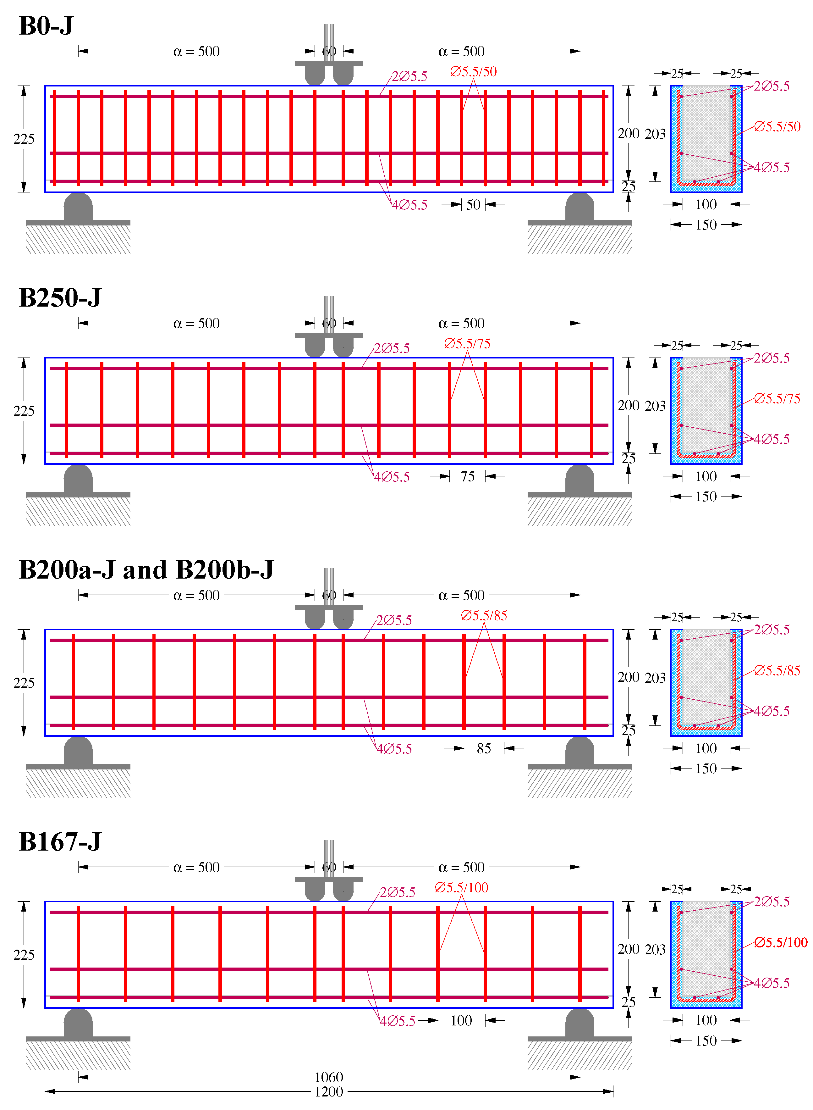
3. Experimental Testing of the Retrofitted Beams

The second part of the project includes the repair and the retesting procedure of the five heavily damaged beams due to the initial loading. The applied retrofitting technique of the initially shear-damaged RC beams with U-shaped jackets aims to recover the original shear capacity and to improve the overall performance. Small-diameter (5.5 mm) mild steel reinforcement in a thin shell (25 mm thick) of a general-purpose cement-based mortar (SikaGrout-212) (Sika Hellas ABEE, Kryoneri, Greece) is the basic feature of the repair technique. Jacket reinforcement has been installed on the surface of the existing RC beam with only a few dowels that were used mainly to enhance connectivity and subsidiary to force transfer at the interface between the existing concrete and the cementitious grout. The latter has been achieved by proper surface preparation prior to the reinforcement installation and the jacketing construction in order to increase the bond characteristics of the existing concrete and the new mortar. It is noted that jacket thickness serves mostly to cover the added fine reinforcement (∅5.5) which consists of longitudinal straight bars and transverse U-shaped open stirrups with yield tensile strength fyv = 225 MPa.
This way, the five jacketed RC beams are 1.2 m long with gross (total) width bj = 150 mm, height hj = 225 mm, effective depth dj = 203 mm, shear span a = 500 mm, and shear span-to-depth ratio a/dj = 2.46, as presented in Figure 4. All jacketed beams have the same additional longitudinal reinforcement; 2∅5.5 bottom bars, 2∅5.5 side bars, and 2∅5.5 top bars. The reinforcing bars of the jacket have been placed directly on the concrete surface of the existing beam, supported by L-shaped ∅5.5 dowels that were epoxy-bonded into holes in the vertical sides of the beams, as shown in Figure 5 and Figure 6. Further, jacketing includes extra U-shaped transverse reinforcement at spacing that varies; 50 mm in the beam with the codified name “B0-J”, 75 mm in beam “B250-J”, 85 mm in beams “B200a-J” and “B200b-J”, and 100 mm in beam “B167-J” (Figure 4).
The mechanical reinforcement ratios of the provided tension bars, ρl fyl/fc, and stirrups, ρv fyv/fc, of each jacketed beam are given in Table 2. Table 2 also presents the mechanical reinforcement ratios of the initial beam and the jacket that have been calculated with regard to the increased (gross) cross-section with width bj = 150 mm and effective depth dj = 203 mm. The value of the total mechanical reinforcement ratio is the sum of these reinforcements. The amount of additional shear reinforcement of the jackets in the form of U-shaped open stirrups varies and it has been designed so that all retrofitted beams have the same mechanical reinforcement ratio. This way, the mechanical reinforcement ratio of the total vertical reinforcement of the jacketed specimens equals to ρv fvy/fc = 0.041. An exception to this rule is the case of beam B0-J, where this ratio is higher (ρv fvy/fc = 0.050) because the initial beam B0 had no stirrups and suffered severe damage.
The repair procedure of the heavily damaged beams that have failed in shear during the initial testing and sustained severe diagonal cracking included the following steps:
  • Surface preparation: (a) Removal of the damaged concrete fragments using a chisel and hammer; (b) cleaning and roughening the concrete surface using a grinder and a small electric concrete breaker, respectively; and (c) abrasive sandblasting to remove debris, dislodge unsound concrete parts, and impart a clean, adequately rough and profiled surface. Thus, the final substrate concrete was not too smooth, too rough, nor too irregular, as shown in Figure 6.
  • Installation of jacketing reinforcement: (a) Drilling 7 mm holes in the vertical sides of the beams for the installation of the dowels; (b) cleaning dust from the holes using compressed air with a thin and long nozzle; (c) filling the holes with epoxy resin (Sikadur-52) (Sika Hellas ABEE, Kryoneri, Greece) using a resin gun; (d) mild steel L-shaped ∅5.5 dowels (see dimensions in Figure 5) were inserted inside the drilled holes and resin flowed out to ensure successful anchoring, whereas their free lengths were carefully placed to support the longitudinal reinforcing bars of the jacket; (e) epoxy-bonded dowels and bars remained still until resin had fully hardened; and (f) installation of the U-shaped open stirrups by welding in the longitudinal bars to be held in place.
  • Casting the cementitious mortar of the jacket: (a) Saturation of the existing concrete surface after cleaning; (b) priming the substrate concrete with a 2 mm thick slush coat of the same jacketing mortar; (c) placing beams into the formwork; and (d) casting-in-place the U-shaped jackets of the beams using the flowable cement-based mortar grout matrix (SikaGrout-212) (Sika Hellas ABEE, Kryoneri, Greece), as shown in Figure 7. The mean compressive and flexural strengths of the cement-based mortar of the jackets were 41.3 MPa and 7.80 MPa, respectively.
As depicted in Figure 5, the clear cover of the steel reinforcement (U-shaped stirrups and dowels) in the proposed thin jacket is rather narrow (14 mm), causing potential durability and steel corrosion issues. According to the provisions of EC2 [60], the minimum cover requirements with regard to durability is 10 mm for structural class S4 (recommended structural class for design working life of 50 years) and exposure class X0 (concrete inside buildings with very low air humidity) or 15 mm for structural class S4 and exposure class XC1 (light hazard of corrosion induced by carbonation), without taking into account any additional protection, such as coating, that could further reduce the minimum cover required (10 mm is the lower limit). Further, the jacketing mortar is a cement-based flowable grout with advanced properties such as high strength, excellent freeze/thaw, oil and water resistance, containing no chloride, and shrinkage compensated. Thus, durability and corrosion effects are rather limited in nonaggressive environmental conditions. However, each repair or strengthening technique has its advantages and drawbacks. Thus, although the applied cementitious mortar jacket is less sensitive to fire hazards, high temperature, and freeze–thaw effects, it has obviously lower corrosion resistance compared to FRP composite jackets [22,24].
The jacketed beams were subjected to monotonically increasing load up to total failure using the same four-point bending scheme of the initially tested beams. The behavior of the jacketed beams in terms of applied load versus mid-span deflection and the cracking patterns at failure are depicted in Figure 8.
Test results indicate that the damage level of the initially tested beams influences the shear capacity of the repaired beams with U-shaped jackets since the experimentally obtained ultimate applied load of these beams is not in full compliance with the amount of reinforcement provided. Although the geometrical characteristics and the mechanical reinforcement ratios of the jacketed beams are more or less the same (with an exception for the transverse reinforcement of the jacketed beam B0-J, as shown in Table 2), the ultimate shear strength values vary. Especially, beam B0-J with the highest number of stirrups (ρv fvy/fc = 0.050) exhibited the lowest shear capacity in terms of ultimate applied load (Pu = 103.5 kN). Beams B250-J and B200a-J attained higher shear strength (Pu = 130.0 and 131.7 kN, respectively) than specimen B0-J, whereas the shear capacity of beams B200b-J and B167-J was the highest (Pu = 147.7 and 148.7 kN, respectively), although in these four jacketed beams, the mechanical ratio of the shear reinforcement was kept the same and was equal to ρv fvy/fc = 0.041.
Concerning the overall behavior of the retrofitted beams, they seem to have an initial stiff response, practically an “elastic” branch up to a load of approximately 25 kN, until the first flexural cracking appears from the bottom surface at the mid-span of the beams. Subsequently, as the imposed loading increased, the developed cracks spread out and diagonal cracking gradually formed near the supports crossed by the U-shaped stirrups (onset of the shear cracking at load approximately 90 kN). Further increase of the applied load causes an increase of the number, the length, and the width of the inclined cracks. Usually, the initial diagonal crack becomes wider than the subsequent inclined cracks and eventually this crack developed as the critical. Consequently, all retrofitted beams failed in shear. Spalling of cover of the jacketing cementitious mortar was also observed close to the bottom ends of the inclined cracks, due to local decrease of the compression zone depths at those sections resulting from the existence of the shear cracks. Debonding failure between the core concrete of the initial beam and the mortar of the jacket has not been observed before the development of the critical diagonal cracking and the ultimate capacity of the retrofitted beams. This fact indicates that the interface treatment applied and described previously in the repair procedure proved to be efficient since adequate bond strength has been achieved. The importance and the influence of proper surface preparation and installation of the jacketing reinforcement on the strength of the jacketed RC beam have long been recognized [61,62].

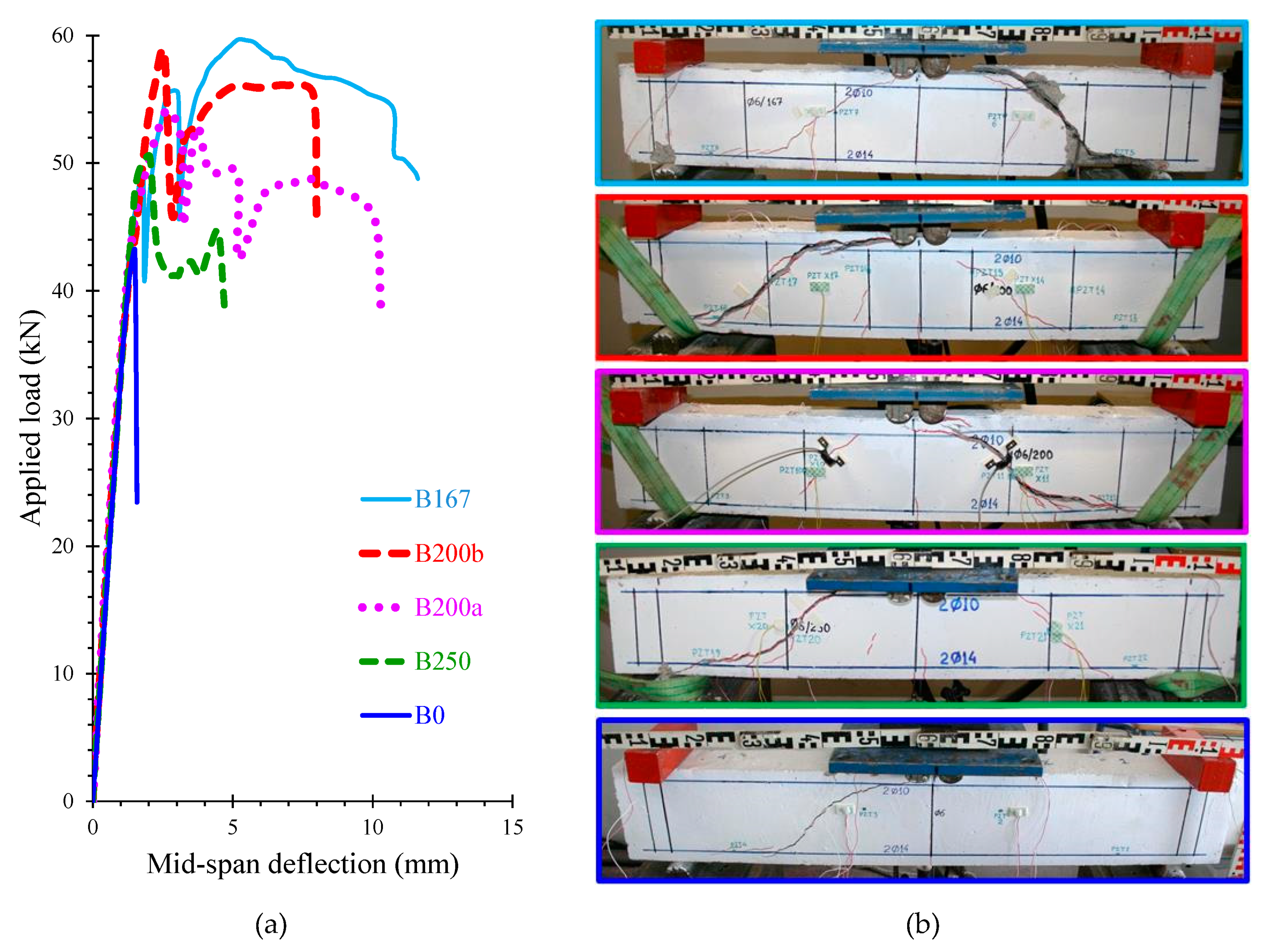
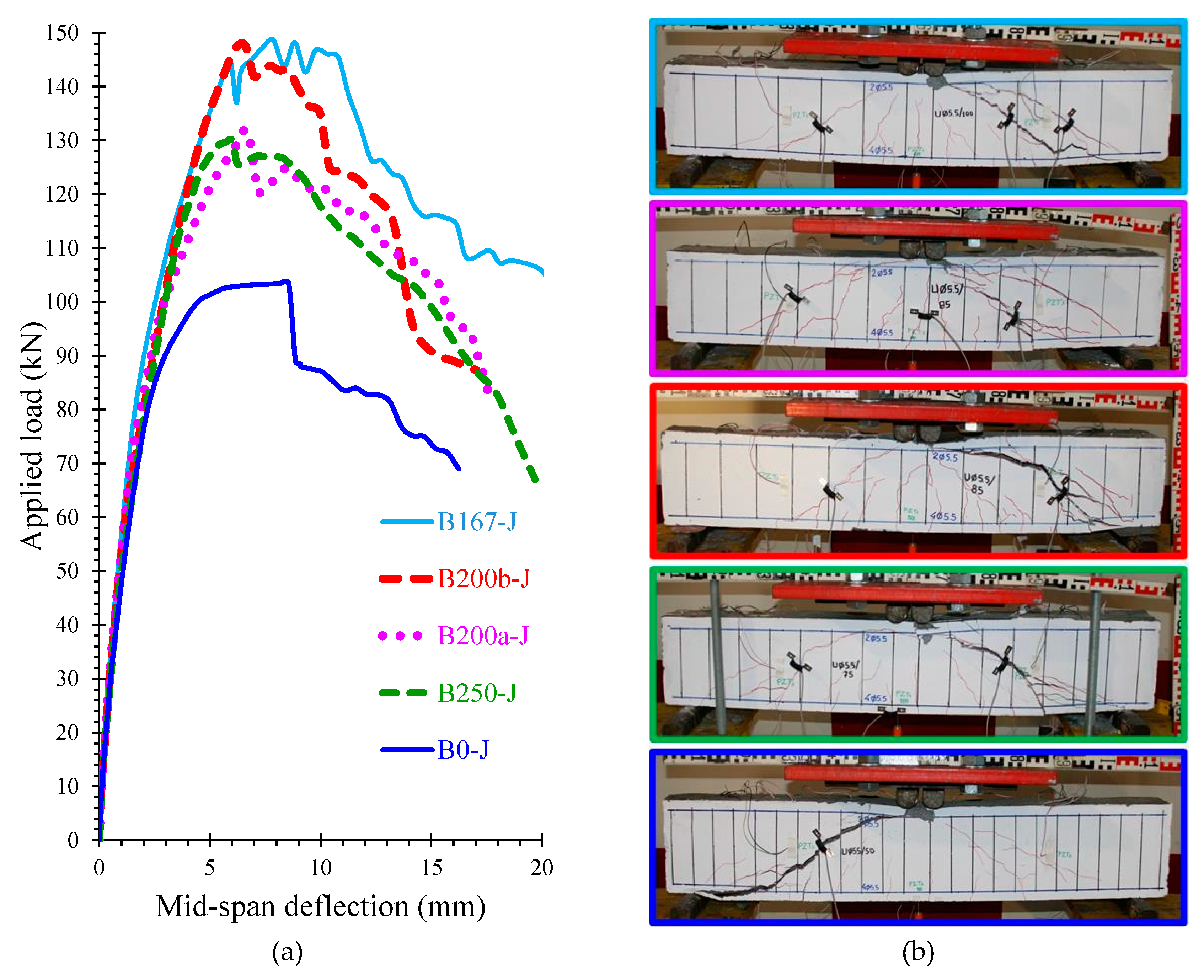
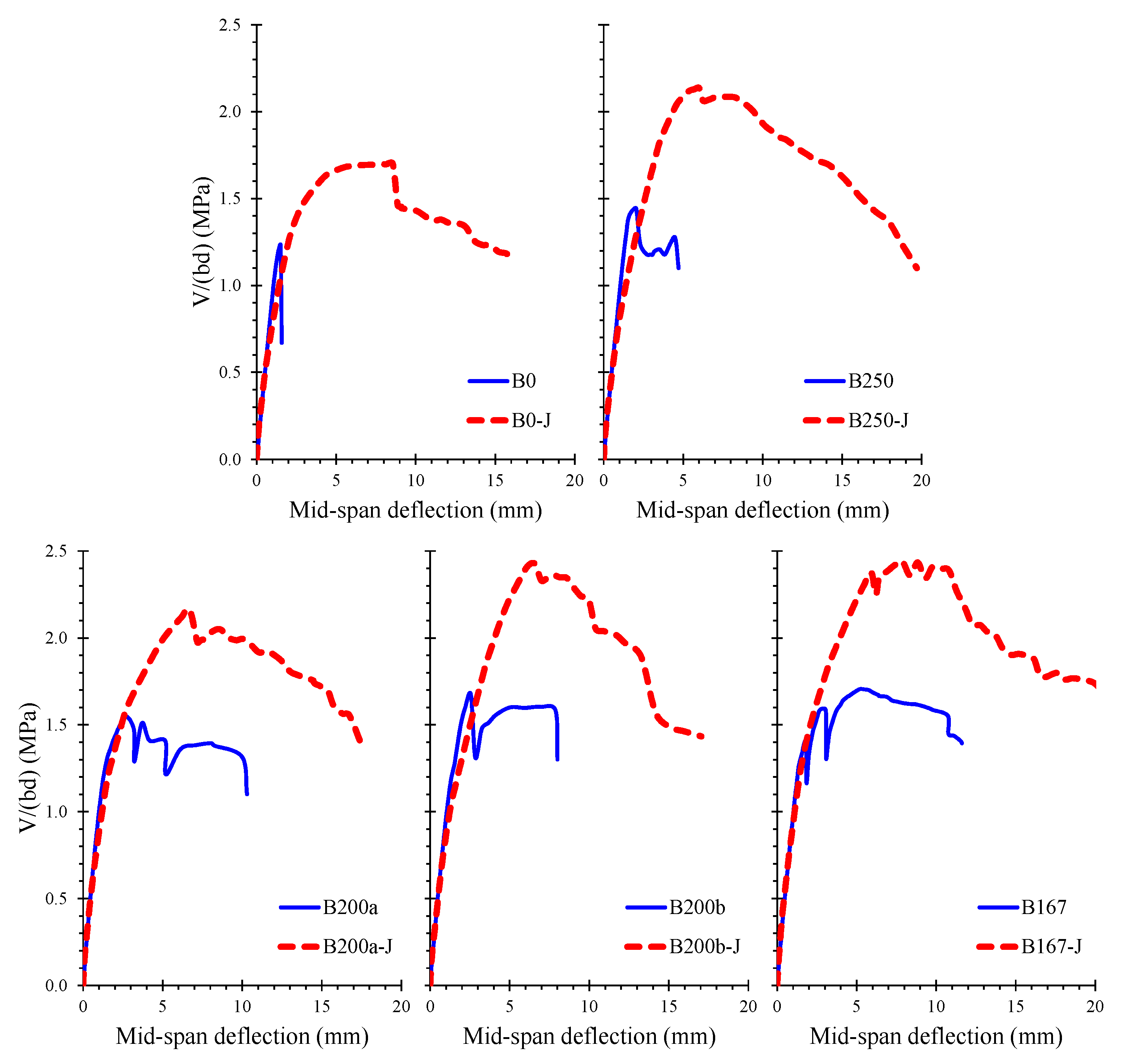
4. Comparisons and Discussion of Test Results

The experimental curves of average shear stress versus mid-span deflection of the initially tested beams are compared with the curves of the corresponding retrofitted and retested beams in Figure 9. From these comparisons, it is obvious that the applied jacketing technique successfully rehabilitates the heavily shear-damaged beams since the shear strength has been fully regained and the overall performance has been improved significantly.
To enable a better understanding of the effectiveness of the applied jacketing technique, Table 3 presents and compares the test results of all examined beams. The following experimental results are included in Table 3:
  • Applied load, PFLC, and corresponding average shear stress, vFLC, for the formation of the first flexural crack.
  • Applied load, PODC, and corresponding average shear stress, vODC, at the onset of diagonal cracking (formation of the first shear inclined crack).
  • Ultimate applied load, Pu, and corresponding ultimate average shear stress, vu (shear strength).
  • Based on the values of vu, the percentage increase of the shear strength attained in the jacketed beams with respect to the shear strength of the corresponding initially tested beams is also presented in Table 3 as “Shear strength increase”.
  • Maximum acceptable deflection of the beam, δ85%Pu, that corresponds to average shear stress versus deflection point of 85% of the ultimate shear strength that is assumed as the end of the reliable post-peak response range.
  • Based on the values of δ85%Pu, the ratio of the increased maximum acceptable deflection attained in the jacketed beams to the maximum acceptable deflection of the corresponding initially tested beams is also presented in Table 3 as “Deflection increase ratio”.
From the comparisons of the ultimate shear stress values presented in Table 3, it is deduced that all jacketed beams exhibited a noticeable increase of the shear capacity from 38 to 48% with regard to the initial beams. However, it has to be noted that the increase of the shear reinforcement ratio in the jacketed beams with respect to the initially tested beams with stirrups is rather high; from 0.014–0.023 in the initial beams up to 0.041 in the jacketed ones (in terms of ρv fvy/fc ). Thus, although the shear reinforcement ratio has been increased by 1.8 to 2.9 times, the corresponding increase of the shear capacity ranges only from 1.4 to 1.5 times. This is mainly attributed to the level of damage that occurred in the initially tested beams and the U-shaped open stirrups in the jackets compared to the closed stirrups provided in the initial beams.
Another important parameter that demonstrates the enhanced overall performance of the jacketed beams is the increase of the deformation capability, which ranges from four to six times in most of the examined cases. An exception is noticed in jacketed beam B167-J due to the already high deformation capability of the initial beam, B167. Further, jacketed beams demonstrated higher deflections and reduced brittleness of the shear failure with respect to the deflections and failure mode of the initial ones.

5. Comparisons with Test Data from the Literature

There are limited experimental studies available in the literature investigating the effectiveness of U-shaped cement-based fine-reinforced jackets for the repair of shear-damaged RC beams. Test data derived from the study of Chalioris et al. [52] are presented in Table 4 and compared with the experimental results of this study. Table 4 presents the main geometrical, mechanical, and reinforcement characteristics of the collected beams (initially tested specimens and jacketed ones) along with the test results and the observed final failure modes. Test results include the values of the applied load PFLC (for the formation of the first flexural crack), PODC, (onset of the diagonal cracking) Pu (ultimate load), and the ratio of the increased strength attained in the jacketed beams to the strength of the corresponding initially tested beams. Additionally, Table 4 presents the values of δ85%Pu (maximum acceptable deflection of the beam that corresponds to the applied load versus deflection point of the 85% of the ultimate strength that is assumed as the end of the reliable post-peak response range) and the ratio of the increased maximum acceptable deflection attained in the jacketed beams to the maximum acceptable deflection of the corresponding initial ones.
The differences between the experimental program of the present research and the study of Chalioris et al. [52] are focused on the jacketing material, the geometrical characteristics of the specimens, the mechanical reinforcement ratios, and the observed failure modes of the jacketed beams. In this study, a flowable cement-based mortar has been used, the retrofitted specimens have approximately the same mechanical reinforcement ratios, and all beams failed in shear, as presented in Table 4. In the previous study [52], the jackets were made of SCC, the reinforcement ratios varied, and several retrofitted beams exhibited flexural response. In both studies, the initially tested beams are shear-critical and have been severely damaged, while thin (25 mm thick) U-shaped, and mild steel fine-reinforced jackets have been applied.
From these values it is deduced that the jacketed beams exhibited increased load bearing and deflection capacities compared to the corresponding initially loaded beams, confirming most of the known aspects. Since the strength and the deformation ability of the beams have been adequately restored, the applied jacketing can be characterized as a successful repair technique.
Further, an important advantage of this retrofitting method is that in several cases, the jacketed beams showed remarkable modification of the failure mode, from brittle shear in the initial test to ductile flexural. It is noted that in these cases, the increase of the load capacity is rather limited (from 1.3 to 1.5 times) since the tension reinforcing bars yielded. However, the increase of the deflection and ductility capacity is substantial. The potential modification of the failure mode mainly depends on the span-to-depth ratio and on the mechanical ratios of the total tension longitudinal and of the total shear reinforcement. More tests would provide additional data concerning the optimum number of U-shaped stirrups required in a specific shear-critical beam in order for the applied jacket to be capable of altering the failure mode to a more favorable ductile one.
Nevertheless, based on the experimental results of the present study, it is stressed that although the failure mode of the jacketed beams remained brittle shear as in the initially tested beams, the increase of the strength is noteworthy, ranging from 2.4 to 3.0 times. Furthermore, these tests indicated that RC beams with longitudinal reinforcement ratio higher than ρl fly/fc ≥ 0.015–0.020 and ratio of shear reinforcement close to ρv fvy/fc = 0.040 tend to fail in shear.

6. Concluding Remarks

The experimental program presented and discussed herein includes five shear-critical beams with various ratios of stirrups tested under monotonic loading until failure in order to exhibit a different level of damage. Initially tested specimens suffered wide and severe diagonal cracks and failed in a brittle manner. The heavily damaged beams were then retrofitted by U-shaped jackets made of cementitious mortar and reinforced with small-diameter mild steel bars and U-shaped open stirrups. Only a few studies reported in the literature investigate this type of jacketing for the repair of preloaded and severely damaged shear-critical RC beams.
Based on the overall performance of the initial and jacketed beams, it can be deduced that the shear strength, in terms of average shear stress and the deformation capability of the retrofitted beams, was substantially increased compared to the corresponding capacities of the initial beams. The increase of the shear stress ranged from 38 to 48%. Although the retrofitted beams also failed in shear, they exhibited higher deflections and reduced brittleness at failure. Deformation at failure of the jacketed beams increased by up to six times with respect to the initial beams. Further, the level of the initial damage that occurred in the beams during the first load influences the effectiveness of the proposed jacketing technique; although the retrofitted specimens had the same mechanical reinforcement ratio, their ultimate load bearing capacity varied.
The experimental results of this study are also compared with the test data derived from a related study in order to establish the effectiveness of this repair system and clarify the parameters affecting its structural reliability. Although the number of examined specimens was rather limited for deriving sound conclusions, it was found that the retrofitted beams can have an altered failure mode from brittle shear to ductile flexural under certain circumstances. This is an important advantage of the applied jacketing technique.
The potential improvement of the failure mode mainly depends on the span-to-depth ratio and the mechanical ratios of the tension bars and stirrups. However, more tests are required to determine specific design criteria of the optimum reinforcement of the jacket that would be applied in a shear-damaged beam in order to achieve a favorable ductile failure. Nevertheless, test results of this study indicated that RC beams with tension longitudinal bar ratio higher than ρl fly/fc ≥ 0.015–0.020 and ratio of transverse reinforcement close to ρv fvy/fc = 0.040 tend to fail in shear.
The applied U-shaped jacketing can be characterized as a successful repair technique since the strength and the deformation ability of the beams were adequately restored. Further, this retrofitting system provides improved performance efficiency with regard to the traditional thick RC jackets and combines some important advantages of FRP jacketing techniques, such as layer thinness, ease of application, and protection provided by mortar, along with the reliability and ductility of the steel reinforcement.

Author Contributions

All authors contributed extensively to this study, discussed the results and reviews, prepared the manuscript, and agreed to the amendments at all stages of the paper. C.E.C. and V.K.K. prepared the manuscript. M.E.V. and N.A.P. constructed the specimens and performed the tests under the supervision of C.E.C., who designed the experiments.

Funding

This research received no external funding.

Acknowledgments

The authors wish to thank SIKA Hellas for supplying the cementitious grout (SikaGrout 212). The contribution of S. Kellis and V. Kanakaris, Laboratory and Technical Employees of the Reinforced Concrete and Seismic Design of Structures Laboratory, is greatly appreciated. Author Violetta K. Kytinou gratefully acknowledges the financial support received from Eugenides Foundation towards doctoral studies.

Conflicts of Interest

The authors declare no conflict of interest.

References

  1. Karayannis, C.G.; Favvata, M.J.; Kakaletsis, D.J. Seismic behaviour of infilled and pilotis RC frame structures with beam–column joint degradation effect. Eng. Struct. 2011, 33, 2821–2831. [Google Scholar] [CrossRef]
  2. Repapis, C.C. Seismic performance evaluation of existing RC buildings without seismic details. Comparison of nonlinear static methods and IDA. Open Constr. Build. Technol. J. 2016, 10, 158–179. [Google Scholar] [CrossRef]
  3. Lampropoulos, A.P.; Tsioulou, O.T.; Dritsos, S.E. Monolithic coefficient values for design when seismically strengthening RC columns with jackets. J. Earthq. Eng. 2012, 16, 1023–1042. [Google Scholar] [CrossRef]
  4. Rousakis, T.C.; Karabinis, A.I. Substandard reinforced concrete members subjected to compression: FRP confining effects. Mater. Struct. 2008, 41, 1595. [Google Scholar] [CrossRef]
  5. Gudonis, E.; Timinskas, E.; Gribniak, V.; Kaklauskas, G.; Arnautov, A.K.; Tamulėnas, V. FRP reinforcement for concrete structures: State-of-the-art review of application and design. Eng. Struct. Technol. 2013, 5, 147–158. [Google Scholar] [CrossRef]
  6. Rodrigues, H.; Pradhan, P.M.; Furtado, A.; Rocha, P.; Vila-Pouca, N. Structural repair and strengthening of RC elements with concrete jacketing. In Strengthening and Retrofitting of Existing Structures; Costa, A., Arêde, A., Varum, H., Eds.; Springer: Singapore, 2018; Volume 9, pp. 181–198. [Google Scholar]
  7. Ma, C.K.; Apandi, N.M.; Yung, S.C.S.; Hau, N.J.; Haur, L.W.; Awang, A.Z.; Omar, W. Repair and rehabilitation of concrete structures using confinement: A review. Constr. Build. Mater. 2017, 133, 502–515. [Google Scholar] [CrossRef]
  8. Lampropoulos, A.P.; Dritsos, S.E. Modeling of RC columns strengthened with RC jackets. Earthq. Eng. Struct. Dyn. 2011, 40, 1689–1705. [Google Scholar] [CrossRef]
  9. Alhadid, M.M.A.; Youssef, M.A. Analysis of reinforced concrete beams strengthened using concrete jackets. Eng. Struct. 2017, 132, 172–187. [Google Scholar] [CrossRef]
  10. Fukuyama, K.; Higashibata, Y.; Miyauchi, Y. Studies on repair and strengthening methods of damaged reinforced concrete columns. Cem. Concr. Compos. 2000, 22, 81–88. [Google Scholar] [CrossRef]
  11. Bousias, S.N.; Biskinis, D.; Fardis, M.N.; Spathis, A.-L. Strength, stiffness, and cyclic deformation capacity of concrete jacketed members. ACI Struct. 2007, 104, 521–531. [Google Scholar]
  12. Kalogeropoulos, G.I.; Tsonos, A.-D.G. Effectiveness of R/C jacketing of substandard R/C columns with short lap splices. Struct. Monit. Maint. 2014, 1, 273. [Google Scholar] [CrossRef]
  13. Kakaletsis, D.J.; David, K.N.; Karayannis, C.G. Effectiveness of some conventional seismic retrofitting techniques for bare and infilled R/C frames. Struct. Eng. Mech. 2011, 39, 499–520. [Google Scholar] [CrossRef]
  14. Tsonos, A.-D.G.; Rentzeperis, I.P. Investigation of the effectiveness of two styles of R/C jackets in pre-earthquake retrofitting of columns and b/c joints of R/C structures. WIT Trans. Built Environ. 2005, 81. [Google Scholar] [CrossRef]
  15. Al-Salloum, Y.A.; Almusallam, T.H.; Alsayed, S.H.; Mosallam, A.S. Traditional and modern techniques for retrofitting of RC beam-column joints. In Proceedings of the Energy Efficient and Environmentally Compatible Civil Infrastructure Systems, 5th International Engineering and Construction Conference, Irvine, CA, USA, 27–29 August 2008. [Google Scholar]
  16. Altun, F. An experimental study of the jacketed reinforced-concrete beams under bending. Constr. Build. Mater. 2004, 18, 611–618. [Google Scholar] [CrossRef]
  17. Liu, X.; Lu, Z.-D.; Li, L.-Z. The use of bolted side plates for shear strengthening of RC beams: A review. Sustainability 2018, 10, 4658. [Google Scholar] [CrossRef]
  18. Demir, A.; Ercan, E.; Demir, D.D. Strengthening of reinforced concrete beams using external steel members. Steel Compos. Struct. 2018, 27, 453–464. [Google Scholar]
  19. Christidis, K.I.; Vougioukas, E.; Trezos, K.G. Strengthening of non-conforming RC shear walls using different steel configurations. Eng. Struct. 2016, 124, 258–268. [Google Scholar] [CrossRef]
  20. Karayannis, C.G.; Sirkelis, G.M. Strengthening and rehabilitation of RC beam-column joints using carbon-FRP jacketing and epoxy resin injection. Earthq. Eng. Struct. Dyn. 2008, 37, 769–790. [Google Scholar] [CrossRef]
  21. Chalioris, C.E.; Kosmidou, P.-M.K.; Papadopoulos, N.A. Investigation of a new strengthening technique for RC deep beams using carbon FRP ropes as transverse reinforcements. Fibers 2018, 6, 52. [Google Scholar] [CrossRef]
  22. Mosallam, A.S.; Mosalam, K.M. Strengthening of two-way concrete slabs with FRP composite laminates. Constr. Build. Mater. 2003, 17, 43–54. [Google Scholar] [CrossRef]
  23. Tsonos, A.-D.G. Effectiveness of CFRP jackets in post-earthquake and pre-earthquake retrofitting of beam-column subassemblages. Struct. Eng. Mech. 2007, 27, 393–408. [Google Scholar] [CrossRef]
  24. Gribniak, V.; Arnautov, A.K.; Kaklauskas, G.; Jakstaite, R.; Tamulėnas, V.; Gudonis, E. Deformation analysis of RC ties externally strengthened with FRP sheets. Mech. Compos. Mater. 2014, 50, 669–676. [Google Scholar] [CrossRef]
  25. Nguyen-Minh, L.; Rovnak, M. Size effect in uncracked and pre-cracked reinforced concrete beams shear-strengthened with composite jackets. Compos. B Eng. 2015, 78, 361–376. [Google Scholar] [CrossRef]
  26. Triantafillou, T.C.; Papanicolaou, C.G. Shear strengthening of reinforced concrete members with textile reinforced mortar (TRM) jackets. Mater. Struct. 2006, 39, 93–103. [Google Scholar] [CrossRef]
  27. Gopinath, S.; Murthy, A.R.; Iyer, N.R.; Dharinee, R. Investigations on textile-reinforced concrete as cover for RC beams. Mag. Concr. Res. 2016, 68, 1040–1050. [Google Scholar] [CrossRef]
  28. Jabr, A.; El-Ragaby, A.; Ghrib, F. Effect of the fiber type and axial stiffness of FRCM on the flexural strengthening of RC beams. Fibers 2017, 5, 2. [Google Scholar] [CrossRef]
  29. Contamine, R.; Larbi, A.S.; Hamelin, P. Identifying the contributing mechanisms of textile reinforced concrete (TRC) in the case of shear repairing damaged and reinforced concrete beams. Eng. Struct. 2013, 46, 447–458. [Google Scholar] [CrossRef]
  30. Rius, J.M.; Cladera, A.; Ribas, C.; Mas, B. Shear strengthening of reinforced concrete beams using shape memory alloys. Constr. Build. Mater. 2019, 200, 420–435. [Google Scholar] [CrossRef]
  31. Mas, B.; Cladera, A.; Ribas, C. Experimental study on concrete beams reinforced with pseudoelastic Ni-Ti continuous rectangular spiral reinforcement failing in shear. Eng. Struct. 2016, 127, 759–768. [Google Scholar] [CrossRef]
  32. Mas, B.; Biggs, D.; Vieito, I.; Cladera, A.; Shaw, J.; Martínez-Abella, F. Superelastic shape memory alloy cables for reinforced concrete applications. Constr. Build. Mater. 2017, 148, 307–320. [Google Scholar] [CrossRef]
  33. Soman, M.; Mohan, J. Rehabilitation of RC columns using ferrocement jacketing. Constr. Build. Mater. 2018, 181, 156–162. [Google Scholar] [CrossRef]
  34. Behera, G.C.; Rao, T.D.G.; Rao, C.B.K. Torsional behaviour of reinforced concrete beams with ferrocement U-jacketing—Experimental study. Case Stud. Constr. Mater. 2016, 4, 15–31. [Google Scholar] [CrossRef]
  35. Bansal, P.P.; Kumar, M.; Kaushik, S.K. Effect of wire mesh orientation on strength of beams retrofitted using Ferrocement jackets. Int. J. Eng. 2008, 2, 8–19. [Google Scholar]
  36. Li, B.; Lam, E.S.S.; Wu, B.; Wang, Y.Y. Experimental investigation on reinforced concrete interior beam–column joints rehabilitated by ferrocement jackets. Eng. Struct. 2013, 56, 897–909. [Google Scholar] [CrossRef]
  37. Martinola, G.; Meda, A.; Plizzari, G.A.; Rinaldi, Z. Strengthening and repair of RC beams with fiber reinforced concrete. Cem. Concr. Compos. 2010, 32, 731–739. [Google Scholar] [CrossRef]
  38. Achillopoulou, V.D.; Karabinis, A.I. Assessment of concrete columns repaired with fiber reinforced mortar through damage indexes and numerical model. Constr. Build. Mater. 2015, 81, 248–256. [Google Scholar] [CrossRef]
  39. Tsonos, A.-D.G. Steel fiber high-strength reinforced concrete: A new solution for earthquake strengthening of old R/C structures. WIT Trans. Built Environ. 2009, 104, 153–164. [Google Scholar]
  40. Katakalos, K.; Manos, G.; Papakonstantinou, C. Seismic retrofit of R/C T-beams with steel fiber polymers under cyclic loading conditions. Buildings 2019, 9, 101. [Google Scholar] [CrossRef]
  41. Al-Osta, M.A. Exploitation of ultrahigh-performance fibre-reinforced concrete for the strengthening of concrete structural members. Adv. Civ. Eng. 2018, 2018, 8678124. [Google Scholar] [CrossRef]
  42. Tsonos, A.-D.G. Ultra-high-performance fiber reinforced concrete: An innovative solution for strengthening old R/C structures and for improving the FRP strengthening method. WIT Trans. Eng. Sci. 2009, 64, 273–284. [Google Scholar]
  43. Mohammed, T.J.; Bakar, B.H.A.; Bunnori, N.M. Torsional improvement of reinforced concrete beams using ultra high-performance fiber reinforced concrete (UHPFC) jackets—Experimental study. Constr. Build. Mater. 2016, 106, 533–542. [Google Scholar] [CrossRef]
  44. Bahraq, A.A.; Al-Osta, M.A.; Ahmad, S.; Al-Zahrani, M.M.; Al-Dulaijan, S.O.; Rahman, M.K. Experimental and numerical investigation of shear behavior of RC beams strengthened by ultra-high performance concrete. Int. J. Concr. Struct. Mater. 2019, 13, 6. [Google Scholar] [CrossRef]
  45. Tsonos, A.-D.G.; Kalogeropoulos, G.I.; Iakovidis, P.E.; Konstantinidis, D. Seismic retrofitting of pre-1970 RC bridge columns using innovative jackets. Int. J. Struct. Eng. 2017, 8, 133–147. [Google Scholar] [CrossRef]
  46. Murthy, A.R.; Karihaloo, B.L.; Priya, D.S. Flexural behavior of RC beams retrofitted with ultra-high strength concrete. Constr. Build. Mater. 2018, 175, 815–824. [Google Scholar] [CrossRef]
  47. Khosravani, M.R.; Weinberg, K. A review on split Hopkinson bar experiments on the dynamic characterisation of concrete. Constr. Build. Mater. 2018, 190, 1264–1283. [Google Scholar] [CrossRef]
  48. Hou, L.; Wang, J.; Huang, T.; Shen, C.; Aslani, F.; Chen, D. Flexural behaviour of corroded reinforced concrete beams repaired with ultra-high toughness cementitious composite. Constr. Build. Mater. 2019, 211, 1127–1137. [Google Scholar] [CrossRef]
  49. Zhang, X.; Luo, Y.; Wang, L.; Zhang, J.; Wu, W.; Yang, C. Flexural strengthening of damaged RC T-beams using self-compacting concrete jacketing under different sustaining load. Constr. Build. Mater. 2018, 172, 185–195. [Google Scholar] [CrossRef]
  50. Tsakiris, S.A.; Rousakis, T.C.; Karabinis, A.I. Confinement effects and strain transfer in reinforced concrete jackets of different detailing for the strengthening of old-type concrete columns. In Proceedings of the 15th World Conference on Earthquake Engineering, Lisbon, Portugal, 24–28 September 2012. [Google Scholar]
  51. Dubey, R.; Kumar, P. Experimental study of the effectiveness of retrofitting RC cylindrical columns using self-compacting concrete jackets. Constr. Build. Mater. 2016, 124, 104–117. [Google Scholar] [CrossRef]
  52. Chalioris, C.E.; Thermou, G.E.; Pantazopoulou, S.J. Behaviour of rehabilitated RC beams with self-compacting concrete jacketing—Analytical model and test results. Constr. Build. Mater. 2014, 55, 257–273. [Google Scholar] [CrossRef]
  53. Chalioris, C.E.; Pourzitidis, C.N. Rehabilitation of shear-damaged reinforced concrete beams using self-compacting concrete jacketing. ISRN Civ. Eng. 2012, 2012, 816107. [Google Scholar] [CrossRef]
  54. Chalioris, C.E.; Papadopoulos, C.P.; Pourzitidis, C.N.; Fotis, D.; Sideris, K.K. Application of a reinforced self-compacting concrete jacket in damaged reinforced concrete beams under monotonic and repeated loading. Engineering 2013, 2013, 912983. [Google Scholar] [CrossRef]
  55. Karayannis, C.G.; Chalioris, C.E.; Sirkelis, G.M. Local retrofit of exterior RC beam-column joints using thin RC jackets—An experimental study. Earth. Eng. Struct. Dyn. 2008, 37, 727–746. [Google Scholar] [CrossRef]
  56. Georgiadi-Stefanidi, K.; Mistakidis, E.; Perdikaris, P.; Papatheocharis, T. Numerical simulation of tested reinforced concrete beams strengthened by thin fibre-reinforced cementitious matrix jackets. Earth. Struct. 2010, 1, 345–370. [Google Scholar] [CrossRef]
  57. Achillopoulou, V.D. Investigation of load transfer along interfaces of jacketed square columns. Struct. Eng. Mech. 2017, 63, 293–302. [Google Scholar]
  58. Achillopoulou, V.D.; Karabinis, I.A. Investigation of shear transfer mechanisms in repaired damaged concrete columns strengthened with RC jackets. Struct. Eng. Mech. 2013, 47, 575–598. [Google Scholar] [CrossRef]
  59. Achillopoulou, V.D.; Rousakis, T.C.; Karabinis, A.I. Force transfer between existing concrete columns with reinforced concrete jackets subjected to pseudoseismic axial loading. In Proceedings of the 15th World Conference on Earthquake Engineering, Lisbon, Portugal, 24–28 September 2012. [Google Scholar]
  60. European Committee for Standardization. Eurocode 2: Design of Concrete Structures—Part 1-1: General Rules and Rules for Buildings (EN 1992-1-1); CEN: Brussels, Belgium, 2004. [Google Scholar]
  61. Júlio, E.N.B.S.; Branco, F.A.B. Reinforced concrete jacketing—Interface influence on cyclic loading response. ACI Struct. 2008, 105, 471–477. [Google Scholar]
  62. Tsioulou, O.T.; Lampropoulos, A.P.; Dritsos, S.E. Experimental investigation of interface behaviour of RC beams strengthened with concrete layers. Constr. Build. Mater. 2013, 40, 50–59. [Google Scholar] [CrossRef]
Figure 1. Geometrical characteristics and steel reinforcement arrangement of the initially tested beams (dimensions in mm).
Buildings 09 00146 g001
Figure 2. Experimental setup.
Buildings 09 00146 g002
Figure 3. (a) Experimental behavior of the initially tested shear-critical beams in terms of applied load versus mid-span deflection; (b) cracking patterns at failure.
Buildings 09 00146 g003
Figure 4. Geometrical characteristics and steel reinforcement arrangement of the jackets of the retrofitted beams (dimensions in mm).
Buildings 09 00146 g004
Figure 5. Cross-sectional dimensions and detailed reinforcement layout of the jacketed beams (dimensions in mm).
Buildings 09 00146 g005
Figure 6. Heavily shear-damaged beams after concrete surface preparation (cleaning and roughening) and the installation of the jacketing reinforcement.
Buildings 09 00146 g006
Figure 7. Casting of the U-shaped jackets using a flowable cementitious mortar grout matrix.
Buildings 09 00146 g007
Figure 8. (a) Experimental behavior of the jacketed beams in terms of applied load versus mid-span deflection; (b) cracking patterns at failure.
Buildings 09 00146 g008
Figure 9. Comparison of the experimental behavior of the examined beams (initially tested and jacketed beams) in terms of average shear stress versus mid-span deflection.
Buildings 09 00146 g009
Table 1. Reinforcement ratios and concrete strength of the initially tested beams.
Beam Codified
Name
ρlρl fyl/fcρvρv fyv/fcfc
(MPa)
fct,spl
(MPa)
B01.76%0.340--28.5 (0.53)2.60 (0.26)
B2501.76%0.3250.19%0.01429.8 (1.06)2.30 (0.27)
B200a1.76%0.3340.24%0.01829.0 (0.98)2.32 (0.14)
B200b1.76%0.3280.24%0.01829.5 (0.70)2.40 (0.20)
B1671.76%0.3460.28%0.02328.0 (0.92)2.35 (0.32)
Table 2. Reinforcement ratios of the jacketed beams.
Beam Codified
Name
Tension Reinforcement: ρl fyl/fcShear Reinforcement: ρv fyv/fc
InitialJacketTotalInitialJacketTotal
B0-J0.1950.0250.220-0.0500.050
B250-J0.1870.0240.2110.0090.0320.041
B200a-J0.1920.0240.2160.0120.0290.041
B200b-J0.1890.0240.2130.0120.0290.041
B167-J0.1990.0250.2240.0150.0260.041
Table 3. Test results of the examined beams (initially tested and jacketed beams).
Beam
Codified
Name
PFLC
(kN)
vFLC
(MPa)
PODC
(kN)
vODC
(MPa)
Pu
(kN)
vu
(MPa)
Shear
Strength
Increase
δ85%Pu
(mm)
Deflection
Increase
Ratio
B011.60.3341.81.2043.11.23-1.51-
B0-J22.80.3788.01.44103.51.7038%9.116.0
B25010.30.2942.31.2150.61.45-2.30-
B250-J19.70.3286.01.41130.02.1348%11.925.2
B200a10.80.3141.11.1754.21.55-3.23-
B200a-J29.40.4888.51.45131.72.1640%12.984.0
B200b11.30.3242.11.2058.61.67-2.60-
B200b-J26.00.4395.21.56147.72.4345%10.404.0
B16711.80.3440.81.1759.71.71-10.77-
B167-J25.00.4182.01.35148.72.4443%12.281.1
Table 4. Test data of U-jacketed beams from Chalioris et al. [52] and the present study
Beam
Codified
Name
b/h
and
bj/hj
a/d
and
a/dj
ρlfyl/fcρv fyv/fcPFLC
(kN)
PODC
(kN)
Pu
(kN)
Strength
Increase
Ratio
δ85%Pu
(mm)
Deflection
Increase
Ratio
Failure
Mode 1
Chalioris et al. [52]
A2200/3002.180.2340.00043.777.8108.0-2.0-S
A2-J250/3251.970.1840.06147.2112.4322.33.09.04.5S
B2125/2003.430.0930.00913.725.836.4-18.0-S-F
B2-J175/2252.930.0760.02022.332.355.21.546.62.6S-F
B3125/2003.430.1930.01012.131.956.2-6.0-S
B3-J175/2252.930.1280.03323.335.684.01.5100.916.8F
B4125/2003.430.2240.01713.732.057.2-6.0-S
B4-J175/2252.930.1480.03719.235.479.91.4104.417.4F
B5125/2003.430.2200.02213.728.361.7-9.0-S
B5-J175/2252.930.1460.04023.332.983.01.3103.611.5F
Present study
B0100/2002.860.3400.00011.641.843.1-1.51-S
B0-J150/2252.460.2200.05022.888.0103.52.49.116.0S
B250100/2002.860.3250.01410.342.350.6-2.30-S
B250-J150/2252.460.2110.04119.786.0130.02.611.925.2S
B200a100/2002.860.3340.01810.841.154.2-3.23-S
B200a-J150/2252.460.2160.04129.488.5131.72.412.984.0S
B200b100/2002.860.3280.01811.342.158.6-2.60-S
B200b-J150/2252.460.2130.04126.095.2147.72.510.404.0S
B167100/2002.860.3460.02311.840.859.7-10.77-S
B167-J150/2252.460.2240.04125.082.0148.72.512.281.1S
1 S: Shear failure, F: Flexural failure, S-F: Shear failure after yielding of tension reinforcing bars.

