Numerical Study of Alternative Seismic-Resisting Systems for CLT Buildings

 ,
,  ,
,
Abstract
1. Introduction
1.1. Background
1.2. CLT Buildings
1.3. Scope of the Paper
2. Connection Technologies for CLT Buildings
2.1. Multi-Storey Platform Construction
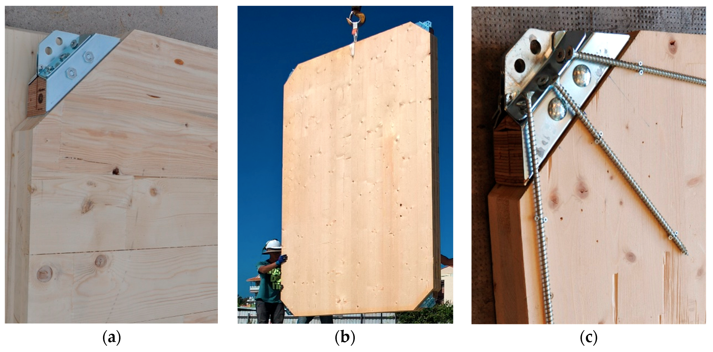
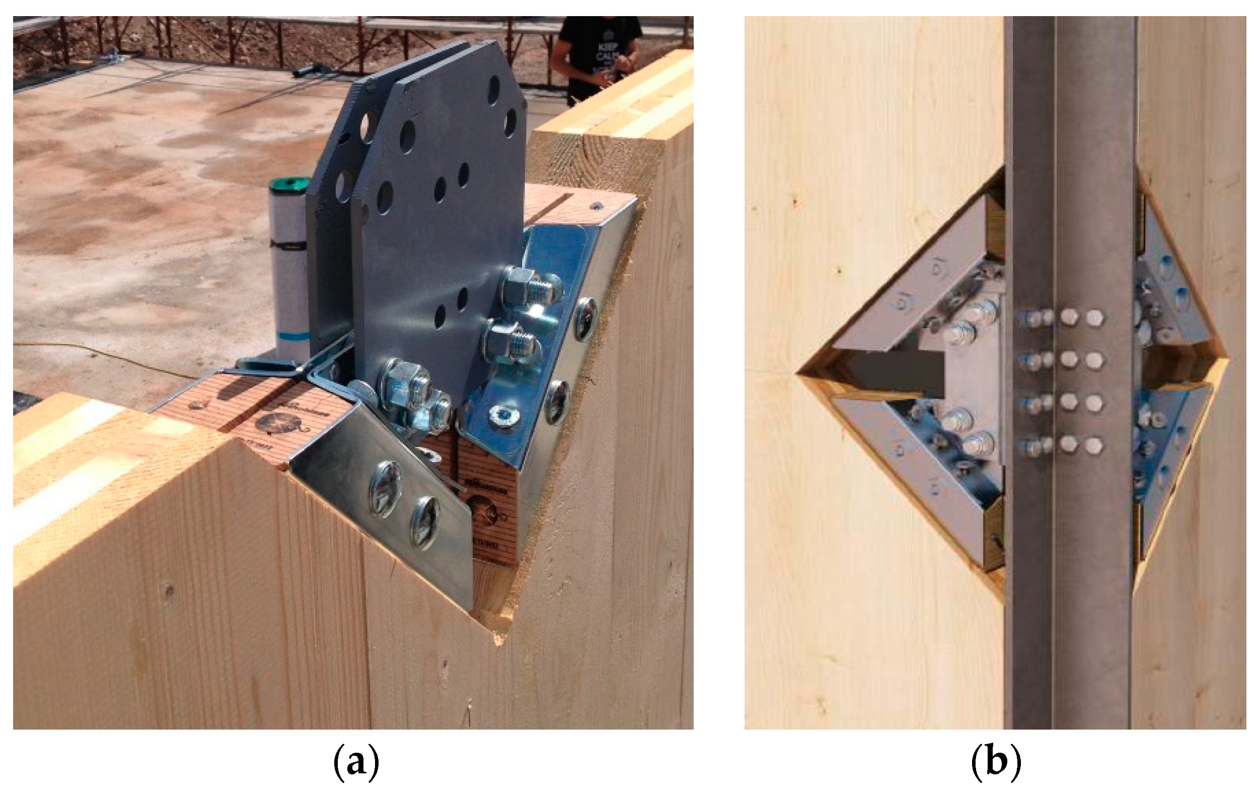
2.2. X-Rad System: Concept and Construction
3. Numerical Studies of SFRS
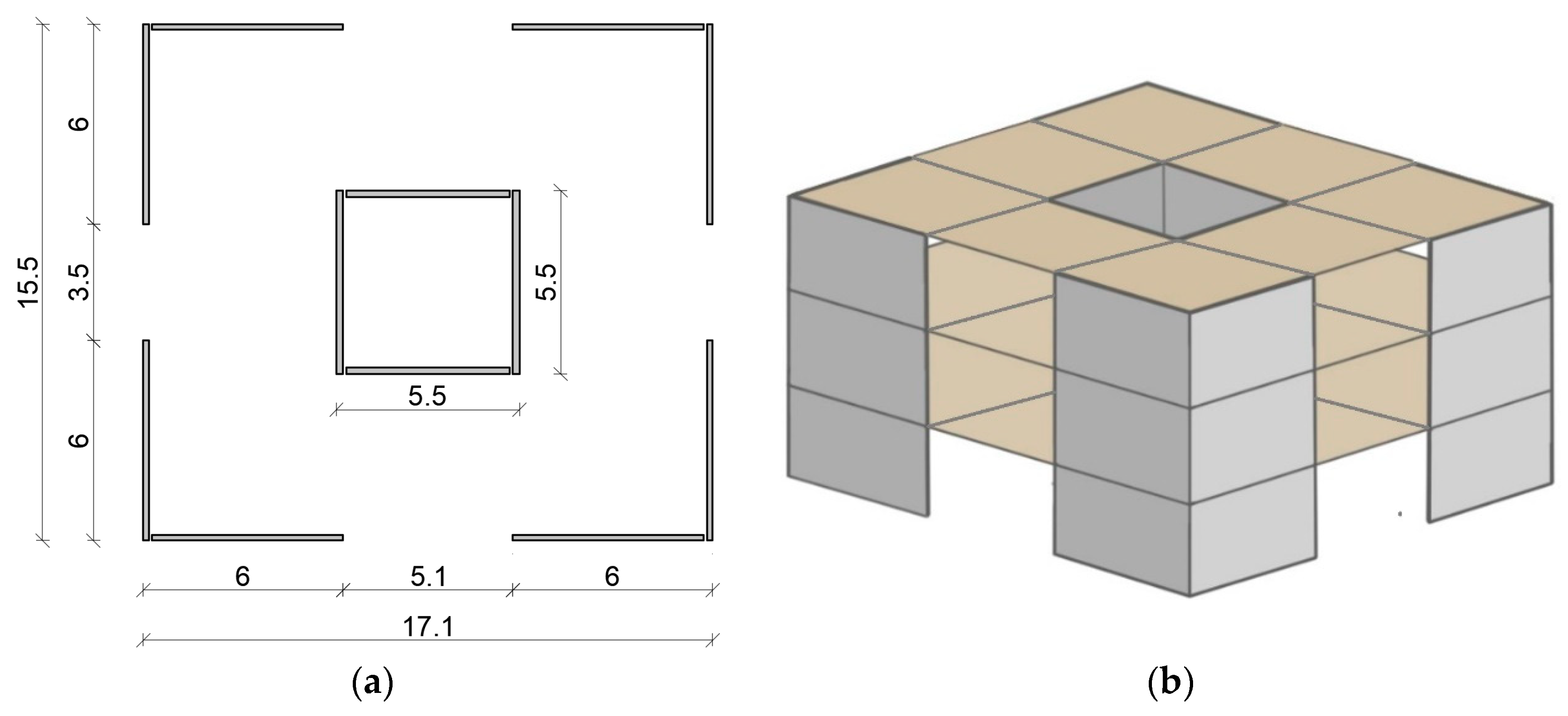
3.1. Cases Study
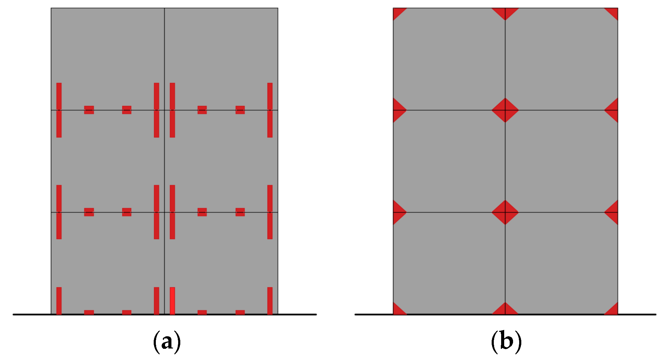
3.2. Design of SFRS
3.3. Mechanical Properties of Materials and Connections
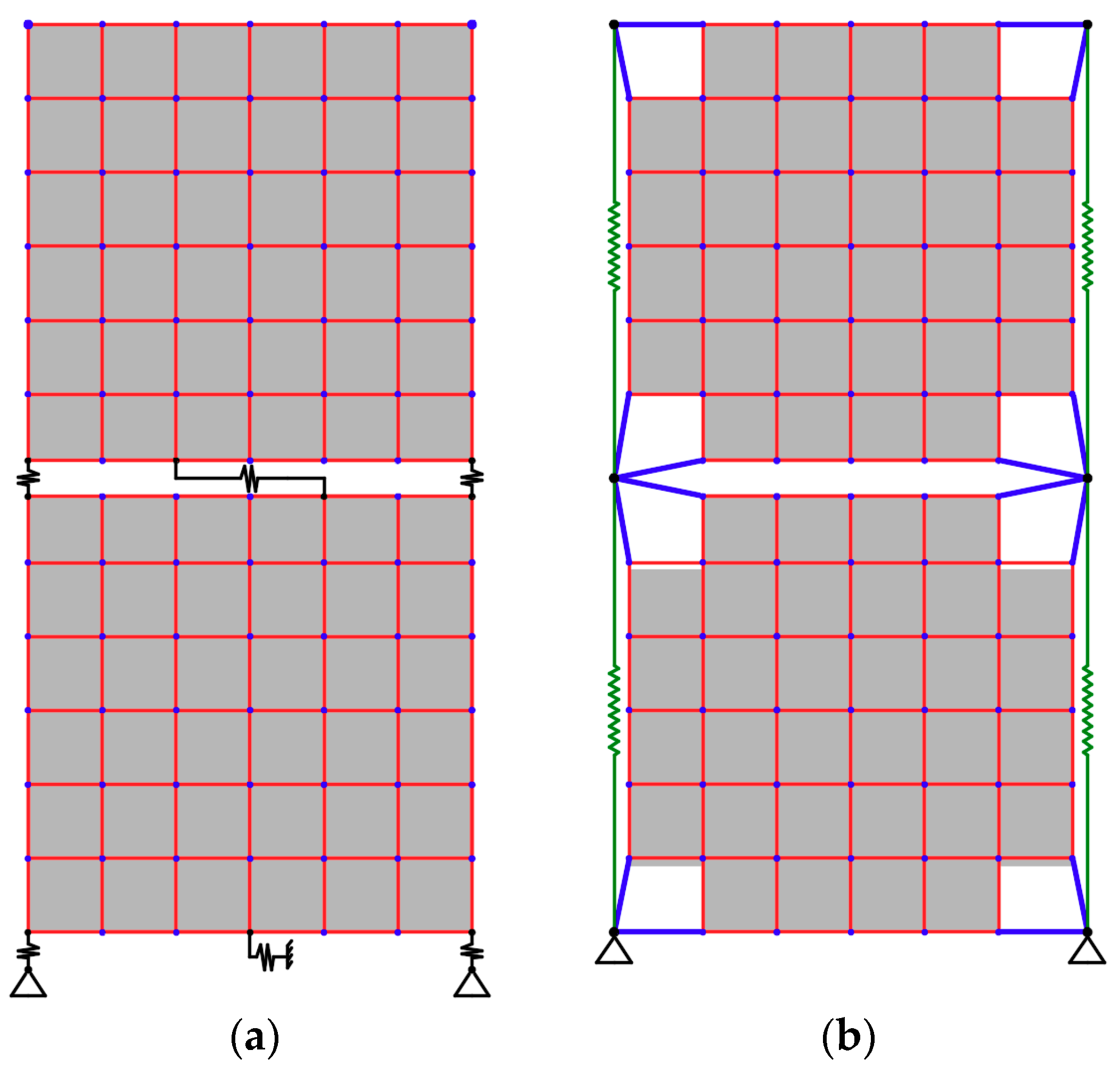
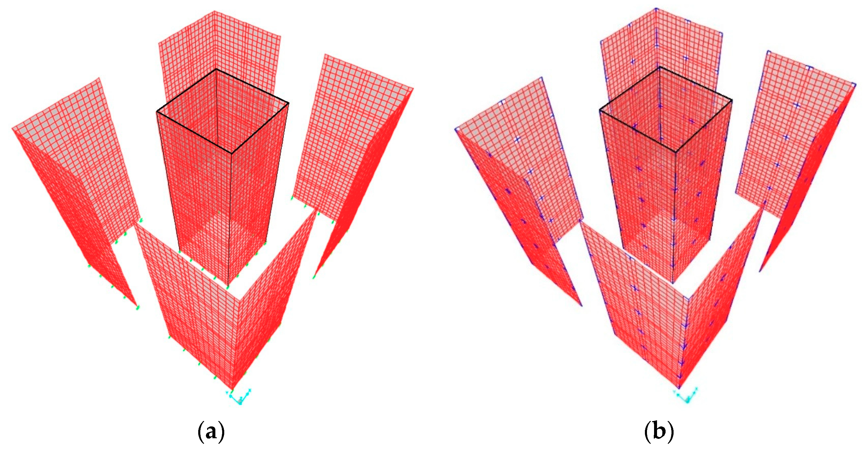
3.4. Finite Element (FE) Models
3.5. Analyses
4. Results
5. Discussion
5.1. Fundamental Elastic Period
5.2. Base Shear Forces
5.3. Uplift Forces
5.4. Lateral Displacement and Inter-Storey Drift
6. Conclusions
- When designing SFRS of superstructures, a clear flow of seismic actions to the foundations needs to be found by defining a proper connection system for the CLT panels’ assembly.
- If LFRS/SFRS have only conventional anchoring connections (e.g., hold-down ties and angle shear brackets), the definition of uncoupled resistant connection patterns between shear and tensile forces is desirable when designing because it ensures a beneficial redundancy of the building when overloaded provided by the actual biaxial bearing capacity of connections.
- Use of innovative X-Rad connections, thanks to their biaxial capacity and related installation pattern at panels’ corners, allows reducing the number of devices needed. However, supplementary tie-downs are necessary for stiffening and strengthening the building with respect to the rocking deformation and uplift forces, respectively. Equivalent linear elastic static force seismic design methods have only limited accuracy even if applicable building superstructure regularity and height requirements, and construction element ductility of applicable design codes are met in full.
- Suitable stiffness and capacity information applicable to proprietary shear wall anchoring connections is available from manufacturers of products, preferably contained in third-party product assessment reports, only for certain devices.
Author Contributions
Funding
Conflicts of Interest
References
- Department of Economic and Social Affairs of the United Nations. World Economic and Social Survey Sustainable Development Challenges; United Nations: New York, NY, USA, 2 July 2013; ISBN 978-92-1-109167-0. [Google Scholar]
- Buchanan, A.H.; John, S.; Love, S. LCA and carbon footprint of multi-storey timber buildings compared with steel and concrete buildings. N. Z. J. For. 2013, 57, 9–18. [Google Scholar]
- Foliente, G.C. History of Timber Construction. In Wood Structures: A Global Forum on the Treatment, Conservation, and Repair of Cultural Heritage STP13370S; Kelley, S., Loferski, J., Salenikovich, A., Stern, E., Eds.; ASTM International: West Conshohocken, PA, USA, 2000; pp. 3–22. [Google Scholar]
- Ghobarah, A. Performance-based design in earthquake engineering: State of development. Eng. Struct. 2001, 23, 878–884. [Google Scholar] [CrossRef]
- Follesa, M.; Vassallo, D.; Christovasilis, I.P. Seismic Design of a 10-Storey CLT Building; FPInnovation: Pointe-Claire, QC, Canada, August 2013. [Google Scholar]
- Xiong, H.B.; Ouyang, L.; Wu, Y. Preliminary design of a novel hybrid tall building with concrete frame-tube and light wood boxes. In Proceedings of the World Conference on Timber Engineering (WCTE), Vienna, Austria, 22–25 August 2016; Eberhardsteiner, J., Winter, W., Fadai, A., Pöll, M., Eds.; Vienna University of Technology: Wien, Austria, 2016. ISBN 978-3-903039-00-1. [Google Scholar]
- Loss, C.; Frangi, A. Experimental investigation on in-plane stiffness and strength of innovative steel-timber hybrid floor diaphragms. Eng. Struct. 2017, 138, 229–244. [Google Scholar] [CrossRef]
- Smith, I.; Frangi, A. Use of Timber in Tall Multi-Storey Buildings; International Association for Bridge and Structural Engineering: Zurich, Switzerland, 8 May 2014; p. 186. ISBN 3857481323. [Google Scholar]
- Connolly, T.; Loss, C.; Iqbal, A.; Tannert, T. Feasibility study of mass-timber cores for the UBC tall wood building. Buildings 2018, 8, 98. [Google Scholar] [CrossRef]
- Brandner, R.; Flatscher, G.; Ringhofer, A.; Schickhofer, G.; Thiel, A. Cross laminated timber (CLT): Overview and development. Eur. J. Wood Wood Prod. 2016, 74, 331–351. [Google Scholar] [CrossRef]
- Gavric, I.; Fragiacomo, M.; Ceccotti, A. Cyclic behaviour of typical metal connectors for cross-laminated (CLT) structures. Mater. Struct. 2015, 48, 1841–1857. [Google Scholar] [CrossRef]
- Ceccotti, A.; Sandhaas, C.; Okabe, M.; Yasumura, M.; Minowa, C.; Kawai, N. SOFIE project—3D shaking table test on a seven-storey full-scale cross-laminated timber building. Earthq. Eng. Struct. 2013, 42, 2003–2021. [Google Scholar] [CrossRef]
- Tomasi, R.; Smith, I. Experimental characterization of monotonic and cyclic loading responses of CLT panel-to-foundation and angle bracket connections. J. Mater. Civ. Eng. 2015, 27, 04014189. [Google Scholar] [CrossRef]
- Dujic, B.; Aicher, S.; Zarnic, R. Investigation on in-plane loaded wooden elements—Influence of loading on boundary conditions. Otto Graf J. 2005, 16, 259–272. [Google Scholar]
- Popovski, M.; Pei, S.; van de Lindt, J.W.; Karacabeyli, E. Force modification factors for CLT structures for NBCC. In Materials and Joints in Timber Structures; RILEM Bookseries 9; Aicher, S., Reinhardt, H.W., Garrecht, H., Eds.; Springer: Dordrecht, The Netherlands, 2014; pp. 543–553. [Google Scholar]
- Ni, C.; Popovski, M. Mid-Rise Wood Frame Construction Handbook SP-57E; FPInnovation: Pointe-Claire, QC, Canada, 2015. [Google Scholar]
- Polastri, A.; Izzi, M.; Pozza, L.; Loss, C.; Smith, I. Seismic analysis of multi-storey timber buildings braced with a CLT core and perimeter shear-walls. Bull. Earth. Eng. 2018, 1–20. [Google Scholar] [CrossRef]
- Scotta, R.; Marchi, L.; Trutalli, D.; Pozza, L. A dissipative connector for CLT buildings: Concept, design and testing. Materials 2016, 9, 139. [Google Scholar] [CrossRef] [PubMed]
- Karacabeyli, E.; Lum, C. Technical Guide for the Design and Construction of Tall Wood Buildings in Canada; FPInnovation: Pointe-Claire, Montreal, QC, Canada, 2014. [Google Scholar]
- Schneider, J.; Shen, Y.; Stiemer, S.F.; Tesfamariam, S. Assessment and comparison of experimental and numerical model studies of cross-laminated timber mechanical connections under cyclic loading. Constr. Build. Mater. 2015, 77, 197–212. [Google Scholar] [CrossRef]
- Gagnon, S.; Pirvu, C. CLT Handbook: Cross-Laminated Timber; FPInnovation: Pointe-Claire, Montreal, QC, Canada, 2011. [Google Scholar]
- Izzi, M.; Casagrande, D.; Bezzi, S.; Pasca, D.; Follesa, M.; Tomasi, R. Seismic behaviour of Cross-Laminated Timber structures: A state-of-the-art review. Eng. Struct. 2018, 170, 42–52. [Google Scholar] [CrossRef]
- Zhang, X.; Popovski, M.; Tannert, T. High-capacity hold-down for mass-timber buildings. Constr. Build. Mater. 2018, 164, 688–703. [Google Scholar] [CrossRef]
- Kramer, A.; Barbosa, A.R.; Sinha, A. Performance of steel energy dissipators connected to Cross-Laminated Timber wall panels subjected to tension and cyclic loading. J. Struct. Eng. 2015, 142, E4015013. [Google Scholar] [CrossRef]
- Hashemi, A.; Zarnani, P.; Masoudnia, R.; Quenneville, P. Seismic resistant rocking coupled walls with innovative Resilient Slip Friction (RSF) joints. J. Constr. Steel Res. 2017, 129, 215–226. [Google Scholar] [CrossRef]
- Pei, S.; van de Lindt, J.W.; Popovski, M.; Berman, J.W.; Dolan, J.D.; Ricles, J.M.; Sause, R.; Blomgren, H.; Rammer, D.R. Cross laminated timber for seismic regions: Progress and challenges for research and implementation. J. Struct. Eng. 2016, 142, E2514001. [Google Scholar] [CrossRef]
- Pozza, L.; Scotta, R.; Trutalli, D.; Polastri, A.; Smith, I. Experimentally based q-factor estimation of cross laminated timber walls. Proc. ICE Struct. Build. 2016, 169, 492–507. [Google Scholar] [CrossRef]
- Sustersic, I.; Fragiacomo, M.; Dujic, B. Seismic analysis of cross-laminated multistory timber buildings using code-prescribed methods: Influence of panel size, connection ductility, and schematization. J. Struct. Eng. 2016, 142, E4015012. [Google Scholar] [CrossRef]
- Follesa, M.; Fragiacomo, M.; Casagrande, D.; Tomasi, R.; Piazza, M.; Vassallo, D.; Canetti, D.; Rossi, S. The new provisions for the seismic design of timber buildings in Europe. Eng. Struct. 2018, 168, 736–747. [Google Scholar] [CrossRef]
- Pozza, L.; Ferracuti, B.; Massari, M.; Savoia, M. Axial-shear interaction on CLT hold-down connections–Experimental investigation. Eng. Struct. 2018, 160, 95–110. [Google Scholar] [CrossRef]
- RothoBlaas (RB). X-RAD Manual, 2018th ed.; RB: Cortaccia, Bolzano, Italy, 2018. [Google Scholar]
- Polastri, A.; Giongo, I.; Piazza, M. An innovative connection system for CLT structures. Struct. Eng. Int. 2017, 27, 502–511. [Google Scholar] [CrossRef]
- Polastri, A.; Angeli, A. An innovative connection system for CLT structures: Experimental–numerical analysis. In Proceedings of the World Conference on Timber Engineering (WCTE), Quebec City, QC, Canada, 10–14 August 2014. [Google Scholar]
- Polastri, A.; Giongo, I.; Angeli, A.; Brandner, R. Mechanical characterization of a prefabricated connection system for Cross Laminated Timber structures in seismic regions. Eng. Struct. 2018, 167, 705–715. [Google Scholar] [CrossRef]
- European Committee for Standardization (CEN). Design of Structures for Earthquake Resistance. Part 1: General Rules, Seismic Actions and Rules for Buildings. EN 1998-1, Eurocode 8; CEN: Brussels, Belgium, December 2004. [Google Scholar]
- Smith, T.; Fragiacomo, M.; Pampanin, S.; Buchanan, A.H. Construction time and cost for post-tensioned timber buildings. Proc. Inst. Civ. Eng. Constr. Mater. 2009, 162, 141–149. [Google Scholar] [CrossRef]
- Montaldo, V.; Meletti, C.; Martinelli, F.; Stucchi, M.; Locati, M. On-line seismic hazard data for the new Italian building code. J. Earthq. Eng. 2007, 11 (Suppl. 1), 119–132. [Google Scholar] [CrossRef]
- Trutalli, D.; Pozza, L. Seismic design of floor-wall joints of multi-storey CLT buildings to comply with regularity in elevation. Bull. Earthq. Eng. 2018, 16, 183–201. [Google Scholar] [CrossRef]
- Polastri, A.; Pozza, L. Proposal for a standardized design and modelling procedure of tall CLT buildings. Int. J. Qual. Res. 2016, 10, 607–624. [Google Scholar]
- European Committee for Standardization (CEN). EN 338: Structural Timber—Strength Classes; CEN: Brussels, Belgium, October 2009. [Google Scholar]
- European Organisation for Technical Approvals (EOTA). X-Lam Dolomiti-CLT: Cross Laminated Timber (CLT)—Solid Wood Slab Elements to Be Used as Structural Elements in Buildings; European Technical Approval ETA-12/0347; EOTA: Charlottenlund, Denmark, 2012. [Google Scholar]
- RothoBlaas (RB). Wood Connectors and Timber Plates Manual, 2018th ed.; RB: Cortaccia, Bolzano, Italy, 2018. [Google Scholar]
- Casagrande, D.; Polastri, A.; Sartori, T.; Loss, C.; Chiodega, M. Experimental campaign for the mechanical characterization of connection systems in the seismic design of timber buildings. In Proceedings of the World Conference on Timber Engineering (WCTE), Vienna, Austria, 22–25 August 2016; Eberhardsteiner, J., Winter, W., Fadai, A., Pöll, M., Eds.; Vienna University of Technology: Wien, Austria, 2016. ISBN 978-3-903039-00-1. [Google Scholar]
- European Committee for Standardization (CEN). EN 12512, Timber Structures. Test Methods. Cyclic Testing of Joints Made with Mechanical Fasteners; CEN: Brussels, Belgium, 28 September 2005. [Google Scholar]
- European Organisation for Technical Approvals (EOTA). Three-Dimensional Nailing Plate (Angle Brackets and Hold-Downs for Timber-to-Timber or Timber-to-Concrete or Steel Connections); European Technical Assessment ETA-11/0086; EOTA: Charlottenlund, Denmark, 2015. [Google Scholar]
- European Organisation for Technical Approvals (EOTA). Three-Dimensional Nailing Plate (Angle Bracket for Timber-to-Timber or Timber-to-Concrete or Steel Connections); European Technical Assessment 11/0496; EOTA: Nordhavn, Denmark, 2014. [Google Scholar]
- European Organisation for Technical Approvals (EOTA). Rotho Blaas X-RAD, European Technical Approval ETA-15/0632; EOTA: Vienna, Austria, 2015. [Google Scholar]
- Dujic, B.; Strus, K.; Zarnic, R.; Ceccotti, A. Prediction of dynamic response of a 7-storey massive XLam wooden building tested on a shaking table. In Proceedings of the World Conference on Timber Engineering (WCTE), Riva del Garda, Italy, 21–24 August 2010. [Google Scholar]
- Pozza, L.; Savoia, M.; Franco, L.; Saetta, A.; Talledo, D. Effect of different modelling approaches on the prediction of the seismic response of multi-storey CLT buildings. Int. J. Comput. Methods Exp. Meas. 2017, 5, 953–965. [Google Scholar] [CrossRef]
- European Committee for Standardization (CEN). EN 1995-1-1:2004/A2 (2014) Eurocode 5: Design of Timber Structures. Part 1-1: General. Common Rules and Rules for Buildings; CEN: Brussels, Belgium, November 2014. [Google Scholar]


| N | 3 | 5 | 8 |
|---|---|---|---|
| H | 9.0 m | Type A systems | 24.0 m |
| T1* | 0.26 s | 0.38 s | 0.54 s |
| W | 2759 kN | 4767 kN | 7778 kN |
| Sd_el (T1*) | 0.82× g | 0.82× g | 0.78× g |
| Sd (T1*) | 0.51× g | 0.51× g | 0.49× g |
| 3-Storey | 5-Storey | 8-Storey | ||||
|---|---|---|---|---|---|---|
| System | A-3 | B-3 | A-5 | B-5 | A-8 | B-8 |
| Shear reconnection | 6 TTF200 | 4 X-Rad | 8 TTF200 | 4 X-Rad | 9 TTF200 | 4 X-Rad |
| Uplift resistant connection | 2 WHT 620 | 1 X-Rad | 2 WHT 620 | 1 X-Rad | 3 WHT 620 | 1 X-Rad |
| Tie-down | / | / | / | 100 × 25 mm2 S355 steel plate | / | 150 × 25 mm2 S355 steel plate |
| Fundamental Period | 3-Storey | 5-Storey | 8-Storey | |||
|---|---|---|---|---|---|---|
| System | A-3 | B-3 | A-5 | B-5 | A-8 | B-8 |
| T1* (s) | 0.26 | 0.38 | 0.54 | |||
| T1,FEM (s) | 0.38 | 0.64 | 0.59 | 0.69 | 1.14 | 0.97 |
| T1,FEM,n (s) | 0.13 | 0.21 | 0.12 | 0.14 | 0.14 | 0.12 |
| T1,E (s) | 0.30 | 0.50 | 0.80 | |||
| Base Shear and Forces on Walls | 3-Storey | 5-Storey | 8-Storey | |||
|---|---|---|---|---|---|---|
| System | A-3 | B-3 | A-5 | B-5 | A-8 | B-8 |
| Vtot (kN) | 1368 | 1103 | 1853 | 1840 | 2004 | 2265 |
| Vtot,W (-) | 0.50 | 0.40 | 0.39 | 0.38 | 0.26 | 0.29 |
| vsw (kN/m) | 39 | 30 | 53 | 51 | 55 | 65 |
| Uplift Force | 3-Storey | 5-Storey | 8-Storey | |||
|---|---|---|---|---|---|---|
| System | A-3 | B-3 | A-5 | B-5 | A-8 | B-8 |
| Perimeter walls | ||||||
| NHD (kN) | 228 | 167 | 260 | 102 | 340 | 104 |
| NHD,W (-) | 0.08 | 0.06 | 0.06 | 0.02 | 0.04 | 0.01 |
| THD (kN) | - | - | - | 234 | - | 378 |
| THD,W (-) | - | - | - | 0.05 | - | 0.04 |
| Core walls | ||||||
| NHD (kN) | 258 | 150 | 283 | 123 | 403 | 139 |
| NHD,W (-) | 0.09 | 0.05 | 0.06 | 0.03 | 0.05 | 0.02 |
| THD (kN) | - | - | - | 351 | - | 522 |
| THD,W (-) | - | - | - | 0.05 | - | 0.07 |
| Displacement | Level | 3-Storey | 5-Storey | 8-Storey | |||
|---|---|---|---|---|---|---|---|
| System | i | A-3 | B-3 | A-5 | B-5 | A-8 | B-8 |
| ∆1 (mm) | 1 | 12 | 14 | 16 | 15 | 20 | 20 |
| ∆2 (mm) | 2 | 27 | 34 | 31 | 29 | 41 | 42 |
| ∆3 (mm) | 3 | 42 | 53 | 47 | 48 | 61 | 62 |
| ∆4 (mm) | 4 | - | - | 61 | 57 | 81 | 61 |
| ∆5 (mm) | 5 | - | - | 75 | 76 | 99 | 62 |
| ∆6 (mm) | 6 | - | - | - | - | 118 | 76 |
| ∆7 (mm) | 7 | - | - | - | - | 135 | 92 |
| ∆8 (mm) | 8 | - | - | - | - | 152 | 103 |
| Drift | 3-Storey | 5-Storey | 8-Storey | |||
|---|---|---|---|---|---|---|
| A-3 | B-3 | A-5 | B-5 | A-8 | B-8 | |
| θmax (%) | 0.41 | 0.47 | 0.52 | 0.48 | 0.65 | 0.60 |
| θmaxrok (%) | 0.17 | 0.12 | 0.30 | 0.08 | 0.40 | 0.10 |
| θmaxshe (%) | 0.11 | 0.20 | 0.13 | 0.24 | 0.17 | 0.32 |
| θmaxCLT (%) | 0.13 | 0.15 | 0.09 | 0.16 | 0.08 | 0.18 |
© 2018 by the authors. Licensee MDPI, Basel, Switzerland. This article is an open access article distributed under the terms and conditions of the Creative Commons Attribution (CC BY) license (http://creativecommons.org/licenses/by/4.0/).
Share and Cite
Loss, C.; Pacchioli, S.; Polastri, A.; Casagrande, D.; Pozza, L.; Smith, I. Numerical Study of Alternative Seismic-Resisting Systems for CLT Buildings. Buildings 2018, 8, 162. https://doi.org/10.3390/buildings8110162
Loss C, Pacchioli S, Polastri A, Casagrande D, Pozza L, Smith I. Numerical Study of Alternative Seismic-Resisting Systems for CLT Buildings. Buildings. 2018; 8(11):162. https://doi.org/10.3390/buildings8110162
Chicago/Turabian StyleLoss, Cristiano, Stefano Pacchioli, Andrea Polastri, Daniele Casagrande, Luca Pozza, and Ian Smith. 2018. "Numerical Study of Alternative Seismic-Resisting Systems for CLT Buildings" Buildings 8, no. 11: 162. https://doi.org/10.3390/buildings8110162
APA StyleLoss, C., Pacchioli, S., Polastri, A., Casagrande, D., Pozza, L., & Smith, I. (2018). Numerical Study of Alternative Seismic-Resisting Systems for CLT Buildings. Buildings, 8(11), 162. https://doi.org/10.3390/buildings8110162