Article

Effect of Different Adhesives on the Bonding Performance of the CFRP–Steel Interface

1
School of Civil Engineering and Architecture, Suqian University, Suqian 223800, China
2
Jiangsu Province Engineering Research Center of Prefabricated Building and Intelligent Construction, Suqian University, Suqian 223800, China
3
School of Transportation and Civil Engineering, Nantong University, Nantong 226019, China
4
Water Resources Research Institute of Shandong Province, Jinan 250013, China
5
Central Southern China Electric Power Design Institute Co., Ltd. of China Power Engineering Consulting Group, Wuhan 430061, China
*
Author to whom correspondence should be addressed.
Buildings 2026, 16(9), 1697; https://doi.org/10.3390/buildings16091697
Submission received: 19 March 2026 / Revised: 14 April 2026 / Accepted: 21 April 2026 / Published: 26 April 2026
(This article belongs to the Section Building Materials, and Repair & Renovation)

Abstract

This study investigates the influence of adhesive type on the bond performance between CFRP plates and steel interfaces through static tensile double-shear tests. Three types of adhesives (Araldite 420A/B, 2015-1, Sikadur-30CN) were tested under four bond lengths. The results indicate that adhesive strength significantly affects failure characteristics, with distinct material performance differences observed. Bond length influences the stress distribution, enhancing dispersion while potentially altering damage progression. High-performance adhesives exhibit superior shear resistance and fracture energy due to improved viscous properties, whereas moderately plastic adhesives achieve adaptive deformation and durable bonding by enhancing the flow and substrate contact. These findings provide a theoretical basis for material selection in CFRP-strengthened steel structures and offer actionable guidance for structural repair engineering applications.

1. Introduction

As modern engineering structures continue to evolve, carbon fiber reinforced polymer (CFRP) materials have gained widespread application in aerospace, automotive manufacturing, sports equipment, and civil engineering, due to their exceptional properties including low weight, high strength, superior stiffness, and excellent fatigue and corrosion resistance [1,2,3]. These characteristics have led to their extensive use in steel structure reinforcement projects.
Conventional steel reinforcement techniques, such as welding, bolting, and surface coating, often face challenges including residual stress accumulation, bending deformation, and complex implementation processes [4,5]. In contrast, CFRP-bonded steel structures avoid these issues while offering advantages including construction simplicity and reduced maintenance costs.
The bonding performance at the CFRP–steel interface plays a decisive role in determining the overall load-bearing capacity and longevity of composite structures. As the critical medium for stress transfer, adhesive material properties directly influence the interfacial bond strength and durability [6,7]. While epoxy resin-based adhesives dominate the current engineering applications [8], their performance in complex environments remains insufficiently addressed. Significant variations exist among different adhesive types in terms of chemical composition, mechanical characteristics, environmental durability, and cost-effectiveness and construction adaptability. These differences result in distinct failure patterns, bond strength levels, and long-term durability at the CFRP–steel interface. Consequently, a systematic investigation of how different adhesives affect the CFRP–steel interface is crucial for enhancing steel structure reinforcement, optimizing bonding material selection, and improving structural reliability.
In recent years, extensive scholarly investigations have been conducted on the bonding characteristics of the fiber-reinforced polymer (FRP)–concrete [9,10] and FRP–steel interfaces [11]. Two primary methodologies dominate this research domain: the single-shear test and double-shear test, which are both designed to induce shear interaction between CFRP sheets and steel plates for evaluating bonding performance. Within structural reinforcement applications, the CFRP–steel interface durability is influenced by multifactorial conditions. Empirical studies [12] reveal that adhesive layer thickness irregularity critically impacts the load-bearing capacity, with optimal performance observed at 0.5 mm thickness under controlled variance conditions. Furthermore, adhesive materials exhibit distinct behavioral patterns under varying service environments. For instance, Dai et al. [13] demonstrated a significant bond strength reduction at low temperatures through systematic temperature cycling experiments, subsequently developing corresponding theoretical models and standardized testing protocols.
However, a clear research gap remains: although individual adhesive types have been characterized in prior studies, comparative analyses of multiple adhesives under identical experimental conditions are still very limited. Most existing work focuses on a single adhesive or compares results across different studies with varying test setups, making direct comparisons unreliable. Specifically, systematic investigations into how different adhesives affect interfacial failure mechanisms, load–displacement characteristics, shear stress distribution, and bond–slip behavior under the same testing conditions are scarce. This knowledge gap necessitates a comprehensive investigation. Consequently, this study focuses on systematically analyzing adhesive-specific effects on CFRP–steel interface performance. The novelty of this work lies in three aspects: (1) quantitative comparison of peak shear stress, fracture energy, and slip parameters among three adhesives with significantly different mechanical properties; (2) application of 3D-DIC technology to obtain full-field continuous strain distribution, enabling accurate derivation of the bond–slip constitutive relationship; and (3) identification of adhesive-specific failure modes to provide practical guidance for engineering adhesive selection.
Conventional research approaches predominantly rely on single-point mechanical measurements (e.g., strain gauge applications), which suffer from operational constraints including limited measurement coverage, complex installation requirements, and the resultant data limitations. These factors collectively impede accurate assessment of full-field strain distribution in structural components, ultimately compromising the result reliability. To address these challenges, this investigation employs Digital Image Correlation (DIC) technology for the mechanical property evaluation of CFRP–steel specimens with varying adhesive treatments. As a non-contact optical measurement technique, 3D-DIC [13,14] operates by tracking identical pixel coordinates in sequential surface images to reconstruct specimen displacement vectors, thereby enabling full-field displacement mapping. This methodology facilitates real-time monitoring of CFRP–steel interface deformation patterns under load, offering precise insights into stress transfer mechanisms, stress concentration phenomena, and damage propagation processes. Successful applications of this technique by other researchers [14,15] provide a valuable methodological precedent for the present study.
This research aims to elucidate the mechanistic relationships between adhesive properties and CFRP–steel interface performance, establishing a scientific foundation for optimal adhesive selection in structural applications. The findings will further contribute to theoretical advancements in CFRP-reinforced steel structure design and construction practices, ultimately enhancing the structural reinforcement efficacy and long-term durability.

2. Experimental Program

2.1. Raw Materials

This study employed three distinct adhesive systems. The first is the two-component epoxy adhesive Araldite 420A/B (Huntsman Advanced Materials, Basel, Switzerland), which exhibits excellent moisture resistance, high mechanical strength, and superior toughness. Its high-temperature curing process is capable of enhancing the overall performance. The second is Araldite 2015-1 (Huntsman Advanced Materials, Basel, Switzerland), a room-temperature curing two-component paste adhesive. It provides elastic bonding, thixotropic behavior, and outstanding weathering resistance. The third is Sikadur-30CN (Sika AG, Baar, Switzerland), a thixotropic, solvent-free structural adhesive that is primarily composed of epoxy resin and special fillers. It is characterized by high early-stage and ultimate mechanical strength.
The test specimens were fabricated using Q345B steel plates (Baoshan Iron & Steel Co., Ltd., Shanghai, China) with a size of 200 mm × 50 mm × 10 mm and Toray T300 CFRP sheets (Zhongfu Shenying Carbon Fiber Co., Ltd., Lianyungang, China). The CFRP sheets are reinforced with M40J carbon fibers and contain 33% epoxy resin by weight. The mechanical properties of materials are listed in Table 1.

2.2. Specimen Design and Fabrication

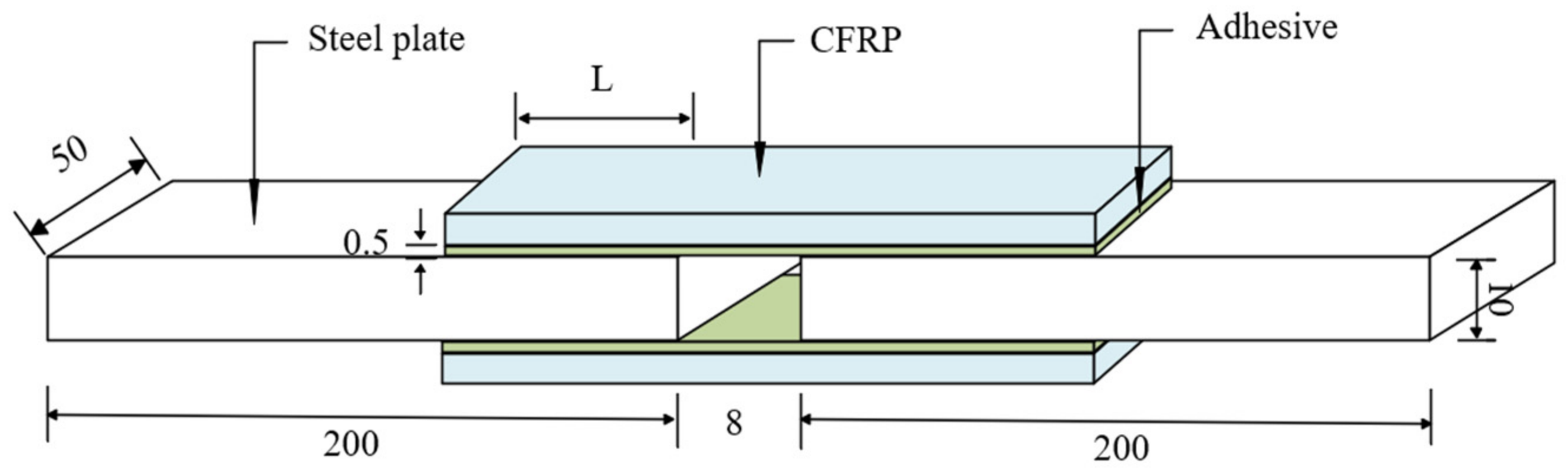
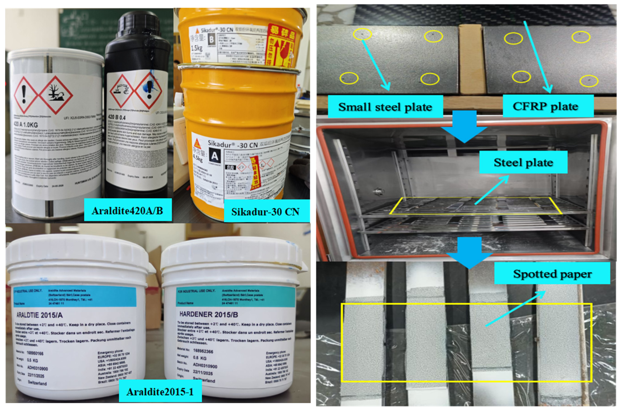
Double-shear specimens (Figure 1, dimensions in mm) consist of two steel plates bonded between the upper and lower CFRP sheets in an axisymmetric layout, with an 8 mm gap maintained by a precision spacer (Figure 2). A total of 24 specimens were prepared (8 per adhesive type: Araldite 420A/B, Araldite 2015-1, Sikadur-30CN), with duplicates for each bond length to ensure reliability, and the adhesive layer thickness was uniformly controlled at 0.5 mm across all specimens. CFRP sheets were designed with four lengths (100 mm, 140 mm, 180 mm, 220 mm), corresponding to effective bond lengths of 40 mm, 60 mm, 80 mm, and 100 mm, respectively. This asymmetric design, adapted from an established methodology [16], ensures that failure initiates consistently within the bonded region, while the CFRP width remains fixed at 50 mm.
Specimens are named using the following format: [adhesive code]-[bond length]-[adhesive thickness]-[relative humidity]-[replicate identifier]. Adhesive codes are 420 (Araldite 420A/B), 2015 (Araldite 2015-1), and Sika (Sikadur-30CN), with replicates marked by ‘a’ or ‘b’ suffixes (e.g., s-420-40-0.5-a/b), and all parameters are listed in Table 2.
The fabrication process begins with surface preparation: steel plates are ground to remove rust and oil, then wiped with acetone, while CFRP sheets are sanded, rinsed with water, dried, and wiped with acetone to enhance interfacial bonding. Next, 0.5 mm steel ball spacers are placed on steel plates to control the adhesive thickness, and adhesives are mixed at weight ratios of 6:5 (Araldite 420A/B), 1:1 (Araldite 2015-1), and 3:1 (Sikadur-30CN) before being evenly applied to CFRP sheets. CFRP sheets are then pressed onto steel plates to expel air bubbles, with the second side bonded after 24 h, and specimens are cured in a temperature-controlled environment for 7 days. Finally, the excess adhesive is removed by sanding, and the CFRP surfaces are coated with white matte paint, dried, and covered with diffusion paper to optimize the contrast for optical measurements.

2.3. Test Loading Device and Procedure

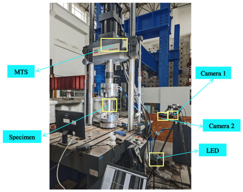
For the double-shear test, the prepared specimens were installed onto the MTS loading system. The load application was performed using an MTS322 fatigue testing machine with a maximum capacity of 500 kN. To prevent relative sliding between the specimen and fixtures during the test, the clamping length for both the upper and lower fixtures was set at 50 mm. The complete test setup is illustrated in Figure 3.
The test was conducted at a loading rate of 0.2 mm/min [17]. A 3D-DIC system (model M230, HF Agile Device Co., Ltd., Hefei, China) with a camera resolution of 1920 × 1080 pixels and a working distance of approximately 400 mm from the specimen was synchronized with the MTS machine to capture the full-field strain at an acquisition frequency of 1 Hz. For speckle pattern preparation, white spray paint was applied as a base coat, followed by black circular random stamp dots that were approximately 0.5 mm in diameter. Prior to loading, the system was calibrated using a calibration board to establish 3D-to-2D spatial mapping. During loading, two cameras synchronously acquired surface images of the specimen.
The ambient lab lighting was dimmed, and LED lamps provided uniform illumination to ensure DIC image quality. Real-time strain distribution was monitored via computer, and loading stopped immediately upon audible specimen failure, with all data saved. Raw data from the DIC system and MTS machine were processed in Origin software (OriginPro 2025 SR1) to calculate and visualize the CFRP surface strain distribution, enabling a quantitative evaluation of the CFRP–steel interface bond performance. This integrated approach ensured effective specimen testing and systematic data analysis.

3. Results and Discussion

3.1. Test Results and Analysis

An investigation of the failure characteristics and modes at the interface between CFRP and steel was crucial for assessing the performance of CFRP-reinforced steel structures. In this study, specimens bonded with three distinct types of adhesives (Araldite 420A/B, Araldite 2015-1, and Sikadur-30CN) were examined. During the initial phase of loading, no visible changes were observed in any of the specimens. The load exhibited a linear increase in correlation with the applied displacement. Upon reaching a critical load threshold, audible signals such as distinct “cracking,” “peeling,” and “popping” sounds emerged.
With a further load increase, stress concentration was prone to develop at specific interfacial regions, which often initiated the onset of interfacial failure. Subsequently, this failure propagated towards the far end of the bond. Due to the inherent brittleness of CFRP and its lack of significant plastic deformation, the CFRP–steel interface typically failed catastrophically, accompanied by a sharp “thud” sound, resulting in a clean, flat fracture surface at the moment of rupture.
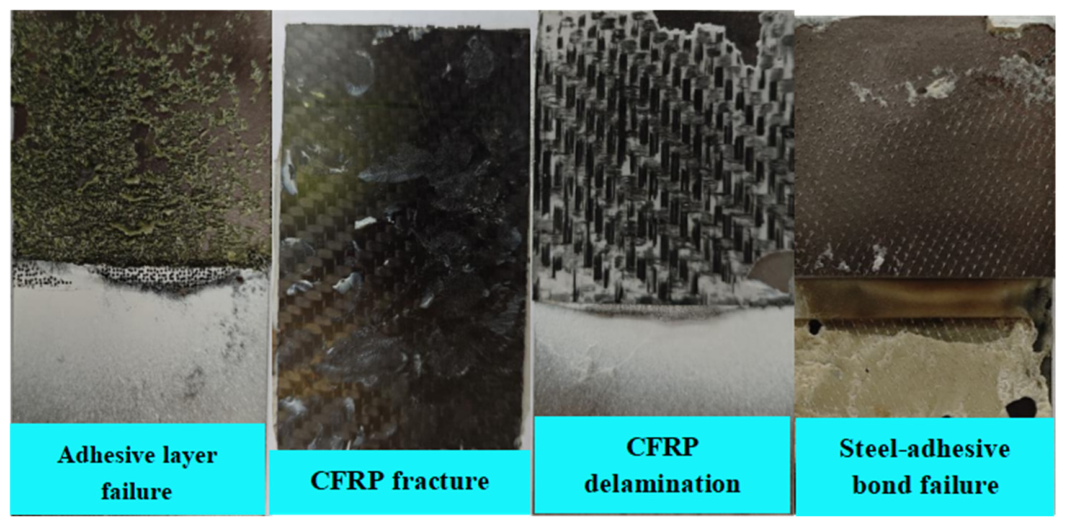
The primary failure modes observed in the specimens were categorized into four types: (a) cohesive failure within the adhesive layer, (b) tensile rupture of the CFRP sheet, (c) delamination between CFRP layers, and (d) mixed-mode failure involving a combination of the aforementioned types. Representative failure patterns are shown in Figure 4. Key experimental data, including the ultimate loads, failure modes, interfacial shear stresses, corresponding slips, and interfacial fracture energies for all specimens, are summarized in Table 2.
Experimental observations revealed distinct bond length-dependent failure modes among the three adhesives. For Araldite 420A/B, cohesive failure within the adhesive layer dominated at 40 mm and 60 mm bond lengths, while CFRP fracture became prevalent at 80 mm and 100 mm. Araldite 2015-1 primarily failed at the steel–adhesive interface, though mixed-mode failures involving interface debonding, adhesive cohesive failure, and CFRP delamination were also observed. Sikadur-30CN induced CFRP delamination at 40 mm and 60 mm, transitioning to CFRP fracture at longer bond lengths of 80 mm and 100 mm.
Analysis linking these failure modes to the mechanical properties of the adhesives shows a correlation with tensile strength rankings: Araldite 420A/B < Araldite 2015-1 < Sikadur-30CN. As a linearly elastic, low-strength adhesive, Araldite 420A/B consistently exhibited cohesive failure within its own matrix. In contrast, Sikadur-30CN, a linearly elastic, high-strength adhesive, transferred stress to the CFRP, causing delamination or fracture.
The bond length also impacted failure initiation. Shorter lengths concentrated the interfacial stress, increasing vulnerability to sudden peeling failures. Beyond a critical length, the stress distribution grew complex, leading to mixed failure modes or CFRP fracture. Longer bond lengths generally elevated the ultimate load by expanding the stress distribution, but this effect plateaued beyond the effective length. For Araldite 2015-1, ultimate loads at 60 mm and 100 mm showed minimal difference—with the 60 mm bond length even marginally higher—as an increased length reduced the interface stiffness and yielded diminishing strength returns.
The ultimate load comparisons indicated that Araldite 420A/B had the highest load-bearing capacity, approximately 1.2 times that of Araldite 2015-1 and Sikadur-30CN, which was attributed to its superior strength and toughness.

3.2. Load–Displacement Curve

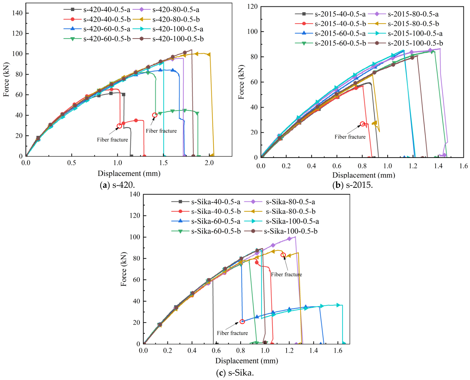
The load–displacement curves in Figure 5 show three distinct stages.
Stage I (Elastic/Linear Stage): At the start of loading, the CFRP–steel interface behaved mainly elastically. Load and displacement increased linearly at a constant rate, indicating an intact interface with stable stiffness.
Stage II (Non-linear/Damage Stage): As the load rose, micro-cracks and local damage began at the interface. The curve slope decreased, meaning that the displacement grew faster than the load. The response became non-linear, and interfacial stiffness started to decline.
Stage III (Failure Stage): After reaching peak load, the interface failed completely. The load dropped rapidly to near zero while displacement jumped sharply. For weaker adhesives, cohesive tearing in the adhesive could start the failure. The final loss of the bond led to structural failure, sometimes involving mixed modes like fiber debonding and interface separation.
For Araldite 420A/B, the peak load generally rose with the bond length because a larger bonded area resists force better. However, this benefit is limited by the effective bond length. Beyond this length, adding more material gives little extra strength, as shown by specimen s-Sika-100-0.5-a having a similar or lower peak load than s-Sika-80-0.5-a. Overly long bonds thus waste material and increase the cost without matching the strength gains.
Comparing curves shows clear adhesive differences. Sikadur-30CN specimens often had a marked post-peak plateau, indicating good ductility. This could be due to high toughness allowing for load redistribution during large deformation, or a shift in failure mode (e.g., from adhesive debonding to CFRP delamination) that temporarily maintains the load. In contrast, Araldite 2015-1 specimens typically showed a sharp, brittle drop after the peak load, with little ductility.
Finally, under the same bond length and thickness, failure displacement increased in the following order: Sikadur-30CN < Araldite 2015-1 < Araldite 420A/B (ignoring small scatter). This order matches the adhesives’ tensile modulus. Sikadur-30CN has a high modulus (3600 MPa), so it deforms less under stress and better resists slip at the interface. Araldite 2015-1 and Araldite 420A/B have lower moduli, making their joints more flexible and leading to larger displacements before failure.

4. Bond Failure Mechanism

4.1. CFRP Strain Distribution

Unlike conventional displacement transducers that provide only global measurements, the 3D-DIC technique enables full-field, non-contact monitoring of local strain and continuous slip distribution along the CFRP–steel interface, which is essential for accurately deriving the bond–slip constitutive relationship.
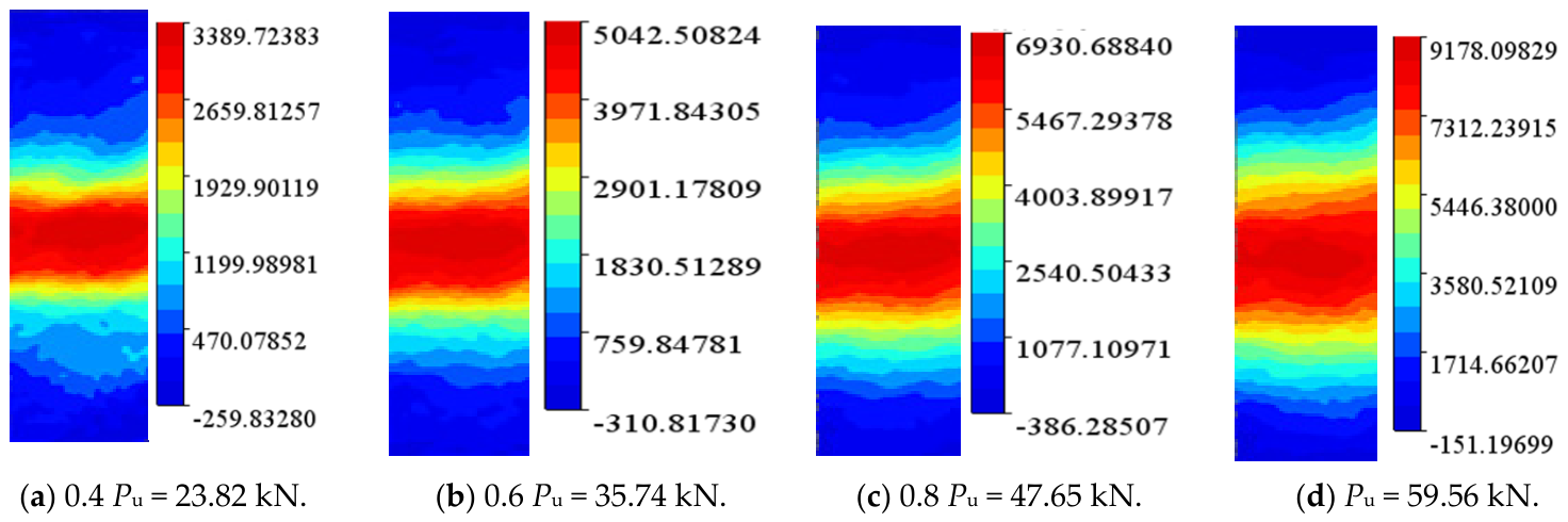
Figure 6 presents the strain distribution, acquired via 3D-DIC, of specimen s-2015-40-0.5-a under progressively increasing loads. The full-field strain contour maps offer a powerful means for visualizing and dynamically quantifying the strain evolution across the bonded interface in real time. This capability provides theoretical and practical insights for predicting the bonding performance of CFRP–steel interfaces, optimizing the structural design, and evaluating the efficacy of reinforcement.
These strain maps effectively reveal regions of localized stress concentration during different loading stages. Such critical areas, highlighted by elevated strain values, correspond to structural weak points that are prone to the initiation of failure (e.g., tearing or debonding).
Analysis of the strain evolution demonstrates a clear and consistent pattern. During the initial loading stage, the zone of significant strain is predominantly localized near the loading end. As the applied load escalates, this high-strain region progressively expands from the loading end towards the free end, illustrating the diffusion of interfacial stress and the propagation of the damage zone.
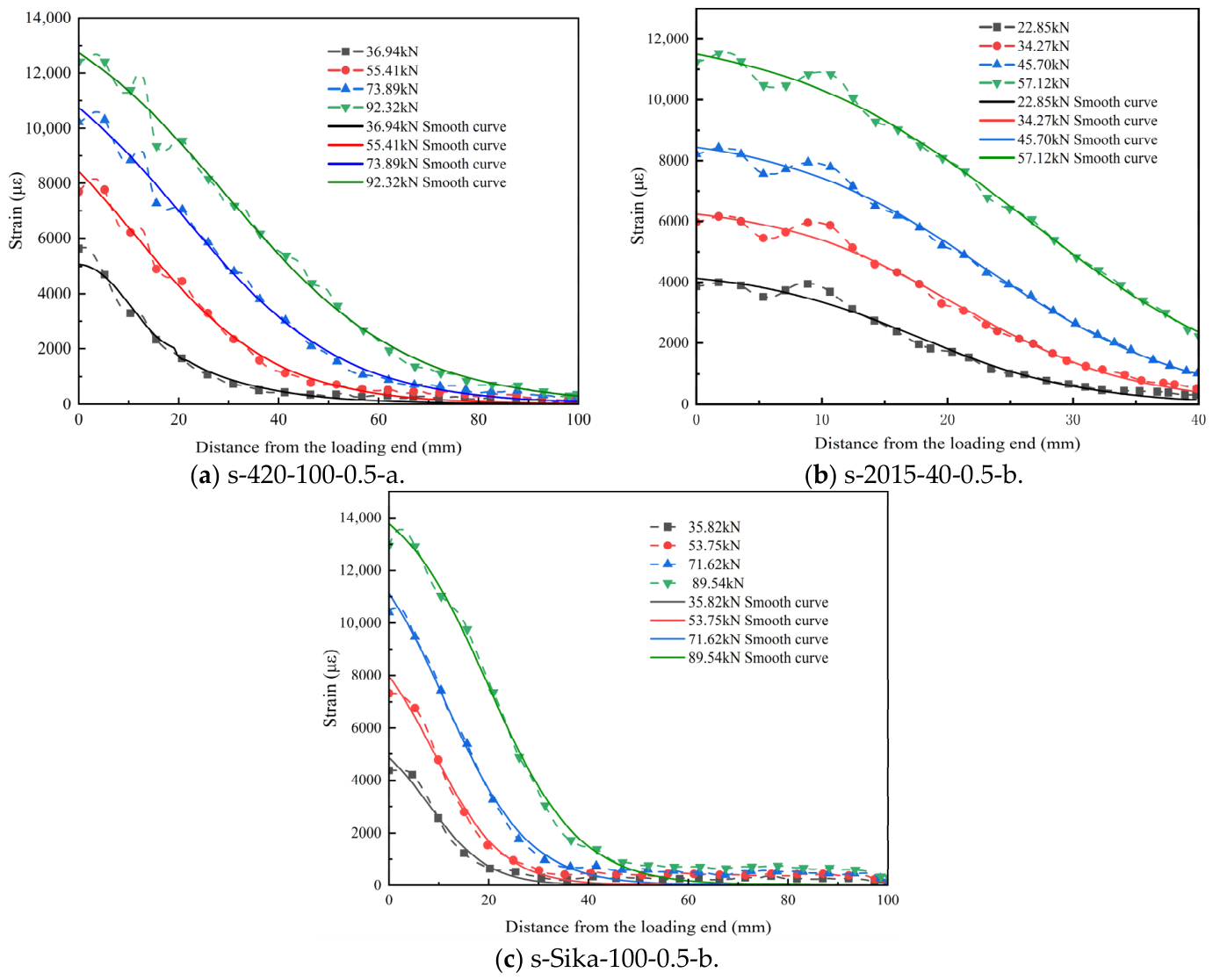
Figure 7 presents the typical strain distribution profiles for the three adhesives, derived from axial strain data of CFRP sheets via 3D-DIC analysis. The curves were plotted using Origin software. For clarity and to represent key loading states, data points corresponding to specific load levels (normalized at 0.4, 0.6, and 0.8 of the peak load) were systematically extracted for plotting. A smoothing process was applied to mitigate the inherent noise and fluctuations in the raw data, which helped to reduce outliers and random noise, thereby revealing the underlying trends in strain development more accurately.
From Figure 7, key observations can be made regarding strain evolution with loading. During initial loading, the strain distribution was relatively uniform and mainly concentrated near the loading end. The bond length had a clear effect: longer bond lengths led to a more pronounced stress concentration at the loading end, due to the extended stress transfer path which tends to localize stress.
As the applied load increased, strain development showed marked divergence. Strain growth near the loaded end significantly outpaced that at the free end, causing the overall strain curve to exhibit a distinct nonlinear shape. This nonlinearity indicates the onset of interfacial debonding and the initiation of internal damage within the bonded structure.

4.2. CFRP–Steel Interface Shear Stress Distribution

The shear stress at the interface plays a critical role in determining the bonding efficacy between composite and metallic structural components. As the load transfer mechanism between CFRP plates and steel substrates relies on adhesive bonding, this interfacial shear stress fundamentally governs the structural load-bearing capacity and long-term durability. For this study, four key assumptions were adopted from prior research [18]: (1) flexural deformation of CFRP elements is considered negligible; (2) the steel substrate is modeled as an ideal rigid body with no deformation; (3) CFRP axial strain exhibits uniform distribution across its thickness dimension; and (4) the influence of normal stresses is excluded from the analysis. The mathematical formulation for interfacial shear stress was derived from Reference [8].
τ ( x ) = E f t f d ε ( x ) d x
where Ef denotes the modulus of elasticity of CFRP; tf is the thickness of the CFRP plate; and ε x is the value of the axial strain from the loading end.
The relative slip s ( x ) of the interface at x from the loading end can be calculated as follows:
s ( x ) = ∫ x L ε f ( x ) d x
where L is the bond length.
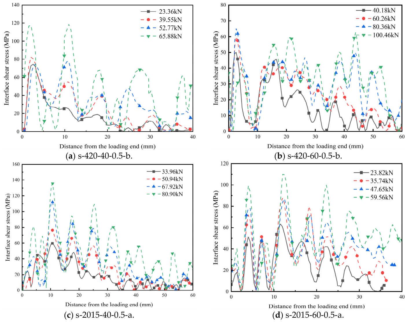
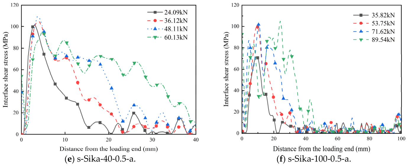
Figure 8 presents the shear stress distribution along the CFRP–steel interface under varying load conditions. The curves show that the stress gradient becomes more pronounced with an increasing load, indicating a stronger stress concentration. During initial loading, the maximum shear stress is concentrated near the loaded end. As the load rises, both the peak shear stress and the distribution curve slope increase progressively, while the shear stress gradually decreases toward the free end.
A comparison of shear stress distribution across different bond lengths shows that shorter lengths result in more localized stress, while longer lengths allow for more extended stress transmission and more uniform distribution. Additionally, under sustained loading, the shear stress tends to stabilize after interfacial damage initiates.

4.3. CFRP–Steel Bond–Slip Constitutive Relationship

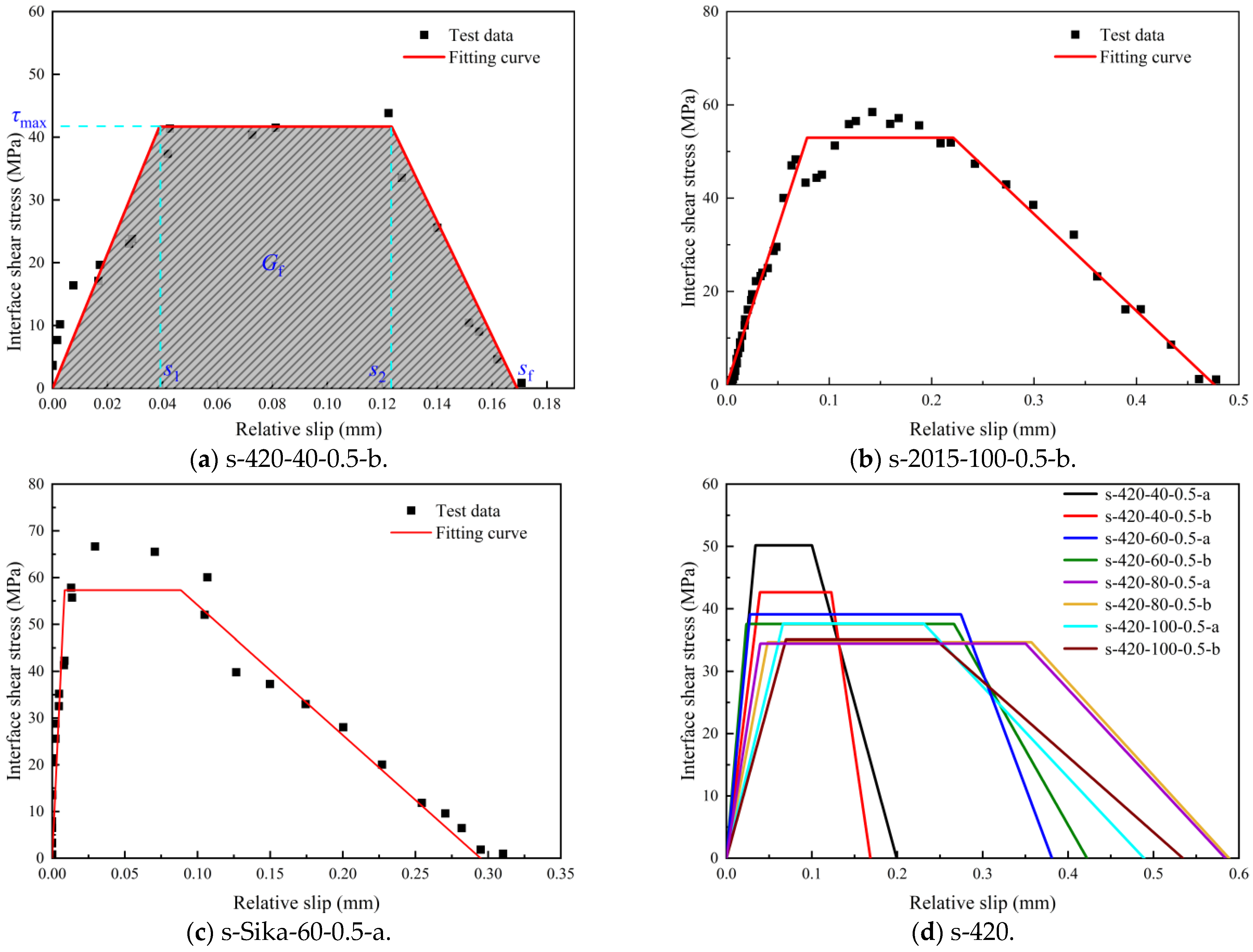
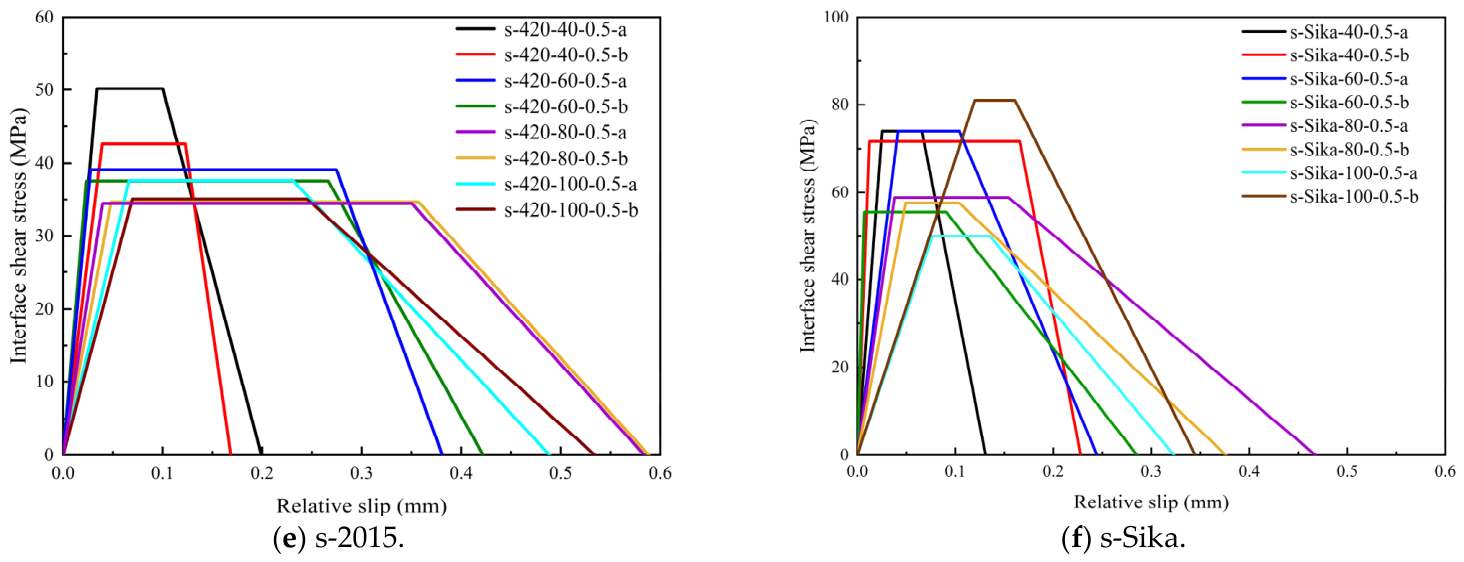
The bond–slip constitutive model captures the relationship between shear stress and relative slip, as well as the process of localized and bond failure in the specimen. Figure 9 shows the bond–slip curves at the CFRP–steel plate interface. Despite differences in adhesive type and bond length, the curves, while showing some dispersion, follow a consistent trend.
The interface force process is divided into three phases. In the initial stage, the shear stress increases linearly with the slip until reaching its peak, indicating an elastic working stage. Then, a plateau phase occurs, during which the interface begins to peel off but the shear stress remains nearly constant within a certain range. Finally, when the relative slip becomes large, localized damage occurs and the shear stress gradually decreases to zero.
To facilitate the study of the bond–slip relationship, the constitutive behavior of all test specimens conforms to the trilinear model described in Refs. [16,19]. The corresponding equations for interfacial shear stress and relative slip are provided below..
τ = τ max ⋅ s s 1 s ≤ s 1 τ max s 1 < s ≤ s 2 τ max ⋅ s f − s s f − s 2 s 2 < s ≤ s f   0 s > s f
where τ is the interfacial shear stress; τmax is the maximum bond shear stress; s1 is the relative slip value corresponding to the maximum shear stress; s2 is the relative slip value corresponding to the stopping of the shear plateau section; sf is the ultimate slip value of the interface; and s f = 2 G f τ max .
The bond–slip curves of all CFRP–steel interface specimens exhibit a characteristic trapezoidal profile, as evidenced by the tri-parametric bond–slip relationship shown in Figure 9. The corresponding bond–slip parameters are systematically compiled in Table 2.
Interfacial fracture energy (Gf) represents the energy dissipation during fracture propagation, serving as a critical parameter for evaluating the interfacial bonding performance. As illustrated in Figure 9a, the integral area under the bond–slip curve quantitatively corresponds to the fracture energy. Enhanced fracture energy contributes to improved material fracture resistance. While Gf is theoretically regarded as an intrinsic property of the interface, independently of bond length, our experimental results show noticeable variations in Gf for specimens using the same adhesive but different bond lengths (e.g., s-420-40 vs. s-420-80). This discrepancy can be attributed to three key factors.
First, the stress concentration in short bond lengths alters the apparent global Gf. For specimens with shorter bond lengths, severe stress concentration occurs near the loaded end, leading to non-uniform stress distribution along the interface. This localized stress state causes premature failure in a small region, rather than full development of the cohesive zone across the entire bond length, resulting in a measured Gf that deviates from the intrinsic value.
Second, failure mode transitions with bond length affect energy dissipation. Short bond lengths tend to fail by abrupt interfacial debonding near the loaded end, which is a process involving minimal energy absorption. In contrast, longer bond lengths exhibit more progressive failure modes, which involve greater energy dissipation, leading to higher measured Gf values.
Third, minor experimental scatter contributes to the observed variations. Unavoidable uncertainties in experimental processes introduce a small amount of variability in test results, even for nominally identical specimens.
The fracture energy initially increases with the effective bonding length before reaching a peak value and subsequently declining. Sikadur-30CN adhesive demonstrates superior fracture energy performance, accompanied by extended effective bonding length and optimized slip characteristics. This favorable slip behavior facilitates effective stress redistribution at the interface, thereby enhancing the overall structural performance.
The experimental results show that both the bond length and adhesive type significantly influence the bond–slip curve parameters. Due to its high shear modulus and two-component epoxy composition, Araldite 420A/B exhibits a steep initial linear segment with high initial stiffness in its bond–slip curve. This enables efficient load transfer even under minimal slip, making it suitable for high-shear-stress applications. The curve then shows a plateau phase with constant shear stress after the peak, indicating a sustained plastic deformation capacity, and concludes with a gentle descending segment that facilitates energy dissipation.
In contrast, Araldite 2015-1 demonstrates a steeper initial rise and a ductile yield plateau, achieving a higher peak shear stress than Araldite 420A/B, which suggests superior resistance to shear deformation. Sikadur-30CN, characterized by its solvent-free and thixotropic properties, shows a steep initial rise with high stiffness but a relatively brief plateau phase, while reaching the highest peak shear stress among the three adhesives.
The slip parameters s1, s2, and sf exhibit positive correlations with bond length, as extended bond lengths permit greater specimen deformation and consequently larger slip displacements. Maximum interfacial shear stress is linearly proportional to adhesive tensile strength, which is a relationship that is applicable to both linear/nonlinear and high/low-strength adhesives. With tensile strengths of 29 MPa (Araldite 420A/B), 31 MPa (Araldite 2015-1), and 40 MPa (Sikadur-30CN), the latter significantly outperforms the former two. Corresponding bond–slip parameter averages in Table 2 confirm this hierarchy: the maximum peak shear stress follows Sikadur-30CN > Araldite 2015-1 > Araldite 420A/B.
Extended bond lengths reduce the maximum shear stress for two main reasons: (1) Stress concentration at the ends makes the shear stress distribution uneven—higher at the ends and lower in the middle. This effect worsens as the bond length increases, reducing the middle region’s contribution. (2) Due to effective length limits, any additional length beyond the effective bond length contributes little to load-bearing. Manufacturing flaws like thickness variations, voids, and impurities further increase the stress concentration. Moreover, in longer bonds, crack propagation dissipates more energy, causing the shear stress to drop once a critical length is reached. Overall, while increasing bond length generally improves load summation, the benefits are limited to the effective range.
As shown in Table 3, peak shear stress varies significantly by adhesive. Araldite 420A/B has the lowest value (38.79 MPa), Araldite 2015-1 reaches 43.37 MPa, and Sikadur-30CN has the highest (65.07 MPa)—49.69% higher than Araldite 420A/B and 65.07% higher than Araldite 2015-1. Sikadur-30CN performs best due to its superior mechanical properties, including a tensile strength of 40 MPa and tensile modulus of 3200 MPa, which are both much higher than those of the other adhesives. The positive correlation between shear stress and tensile strength/modulus shows that stronger adhesives generally offer greater cohesive strength and better resistance to shear slippage. Additionally, the tensile modulus directly affects interfacial shear stress transfer, and high-modulus adhesives transmit loads more effectively.
Regarding slip parameters, Araldite 420A/B shows the highest values—6.82% and 42.42% above the other two groups, respectively—and is roughly 3.2 to 3.8 times higher. Compared to Araldite 2015-1 and Sikadur-30CN, the increase reaches 40% and 44.83%, respectively. This indicates that Araldite 420A/B has greater plastic deformation capacity, enabling effective elastic bonding and better adhesive flow.
For fracture energy, both Araldite 420A/B and Sikadur-30CN show high values, reflecting strong fracture toughness and the ability to absorb significant energy during failure.
In conclusion, adhesive choice greatly affects the CFRP–steel interface performance. Sikadur-30CN excels in shear resistance and load transfer due to its high tensile strength and modulus, leading to higher peak shear stress. Meanwhile, Araldite 420A/B offers superior slip characteristics, indicating better bonding toughness, plastic deformation capability, and adhesive mobility.

5. Conclusions

Based on the systematic investigation of the bond performance at the CFRP–steel interface using a double-shear test system, the conclusions have been revised into a concise three-item numbered list, as follows:
(1)
Research findings (directly addressing objectives): Through double-shear tests, this study reveals that adhesive type and bond length significantly govern the failure mode, shear stress distribution, and bond–slip behavior of the CFRP–steel interface. The predominant failure mechanisms include adhesive–steel debonding, adhesive layer failure, CFRP fracture, and interlayer separation. Among the three adhesives evaluated, Sikadur-30CN demonstrates superior performance with peak shear stress up to 67.7% higher and interfacial fracture energy 20.08% higher than the other adhesives, while Araldite 2015-1 exhibits excellent plastic deformation characteristics with slip parameters exceeding those of Araldite 420A/B and Sikadur-30CN by more than twofold (over 100% higher). The effective bond length is identified as being approximately 80 mm, beyond which the ultimate load tends to stabilize.
(2)
Practical recommendations for engineers: For engineering applications requiring high shear strength and stiffness, Sikadur-30CN is recommended. For scenarios prioritizing deformation adaptability, Araldite 2015-1 is more suitable due to its superior elastic bonding properties that facilitate adaptation to interfacial deformation. The bond length should be designed close to the identified effective bond length (approximately 80 mm) for an economical and efficient design, as an increased bonding length enhances the stress distribution but excessive length can lead to more complex failure patterns. Engineers should leverage the favorable viscous fluidity of Araldite 2015-1 to ensure uniform adhesive distribution at the interface.
(3)
Research limitations and future work: The apparent interfacial fracture energy presented in this study shows variation with bond length, which is attributed to the stress concentration effects and failure mode transition in specimens with shorter bond lengths. This research is limited to monotonic static loading tests under a single environmental condition, utilizing only three specific adhesive types (Araldite 420A/B, Araldite 2015-1, and Sikadur-30CN) with bond lengths of 40, 60, 80, and 100 mm. Performance under varying environmental conditions, other adhesive formulations, and particularly fatigue and long-term durability assessment were not investigated and remain important subjects for future work.

Author Contributions

Conceptualization, L.G. and C.S.; Methodology, Q.W.; Software, Q.W. and M.Z.; Validation, W.G. and F.G.; Formal analysis, Q.W. and M.Z.; Investigation, W.G., L.L., M.Z. and F.G.; Resources, L.G. and F.G.; Data curation, W.G. and L.L.; Writing—original draft, Q.W. and L.G.; Writing—review & editing, L.G. and M.-L.Z.; Visualization, W.G., L.G., L.L., C.S. and F.G.; Supervision, L.G. and C.S.; Project administration, L.G. and M.-L.Z.; Funding acquisition, L.G., M.-L.Z. and C.S. All authors have read and agreed to the published version of the manuscript.

Funding

This research has been supported by the Shandong Provincial Natural Science Foundation (ZR2024QE147).

Data Availability Statement

The data presented in this study are available in this article.

Conflicts of Interest

Author Fuhe Ge was employed by the company Central Southern China Electric Power Design Institute Co., Ltd. of China Power Engineering Consulting Group. The remaining authors declare that the research was conducted in the absence of any commercial or financial relationships that could be construed as a potential conflict of interest.

References

  1. Islam, N.; Miyashita, T.; Ono, K. Repair of damaged composite girders using CFRP sheets considering limit state condition. J. Constr. Steel Res. 2024, 218, 108733. [Google Scholar] [CrossRef] [Scilit]
  2. Fam, A.; Dougall, C.M.; Shaat, A. Performance of CFRP-confined concrete-filled double-skin steel tube columns with CHS outer and inner under concentric compression. Structures 2026, 84, 110941. [Google Scholar]
  3. Harrach Dániel, H.; Muayad Habashneh, M.; Rad, M.M. Reliability-based numerical analysis of glulam beams reinforced by CFRP plate. Sci. Rep. 2022, 12, 13587. [Google Scholar] [CrossRef] [Scilit] [PubMed]
  4. Zhuang, M.; Wang, S.; Sun, C. Experiment and numerical simulation investigation for crack growth of deck-to-rib welded details in orthotropic steel bridge decks. Structures 2021, 41, 1109–1121. [Google Scholar] [CrossRef] [Scilit]
  5. Li, J.; Su, S.; Wang, W. Research on fatigue crack propagation behavior and reliability evaluation of steel bridge. J. Constr. Steel Res. 2025, 228, 109421. [Google Scholar] [CrossRef] [Scilit]
  6. Li, C.; Gao, Y.; Wang, X.; Li, Y.; Sidu, Y. Effect mechanism of temperature on the interface properties of CFRP-steel bonded by self-developed adhesive. Acta Mater. Compos. Sin. 2024, 41, 925–936. [Google Scholar]
  7. Wang, D. Research on Moisture and Heat Resistance of Underwater Curable Adhesive and Its Bonding with Steel. Master’s Thesis, Harbin Institute of Technology, Harbin, China, 2021. [Google Scholar]
  8. Wang, T.; Guo, Q.; Zhang, T.C.; Zhang, Y.; Yuan, S. Large-scale prepared superhydrophobic HDTMS-modified diatomite/epoxy resin composite coatings for high-performance corrosion protection of magnesium alloys. Prog. Org. Coat. 2022, 170, 106999. [Google Scholar] [CrossRef] [Scilit]
  9. Sneed, L.H.; Verre, S.; Ombres, L.; Carloni, C. Flexural behavior RC beams strengthened and repaired with SRP composite. Eng. Struct. 2022, 258, 114084. [Google Scholar] [CrossRef] [Scilit]
  10. Nerilli, F.; Ahmadi, H.M.; Imperatore, S.; Vairo, G. Bond–Slip Performance of GFRP Rebars in Concrete Under Alkaline and Thermal Conditioning. J. Compos. Sci. 2026, 10, 131. [Google Scholar] [CrossRef] [Scilit]
  11. Zhuang, M.; Yu, X.; Chen, Y.; Hang, Z.; Wang, M.; Wang, Y.; Gao, L.; Sun, C. Effect of curing temperature on bonding fatigue performance of CFRP-steel interface. J. Constr. Steel Res. 2025, 229, 109433. [Google Scholar] [CrossRef] [Scilit]
  12. Li, X.; Li, X.; Li, T. Influence of uneven thickness of bonding layer on the bonding performance of CFRP-steel interface. Acta Mater. Compos. Sin. 2024, 42, 4024–4040. [Google Scholar]
  13. Zhu, S. Study on Shear Behavior of Bonding Interface Between CFRP and Steel Plate Under Variable Temperature Field. Master’s Thesis, Anhui Jianzhu University, Hefei, China, 2019. [Google Scholar]
  14. Tang, J.; Chen, X.; Dai, F.; Wei, M. Experimental investigation of fracture damage of notched granite beams under cyclic loading using DIC and AE techniques. Fatigue Fract. Eng. Mater. Struct. 2020, 43, 1583–1596. [Google Scholar] [CrossRef] [Scilit]
  15. Wang, H.; Wu, G.; Dai, Y.; He, X. Experimental study on bond behavior between CFRP plates and steel substrates using digital image correlation. J. Compos. Constr. 2016, 20, 4016054. [Google Scholar] [CrossRef] [Scilit]
  16. Nguyen, T.C.; Bai, Y.; Zhao, X.L.; Al-Mahaidi, R. Curing effects on steel/CFRP double strap joints under combined mechanical load, temperature and humidity. Constr. Build. Mater. 2013, 40, 899–907. [Google Scholar] [CrossRef] [Scilit]
  17. Gao, L.; Deng, Z.; Zhuang, M. Experimental study on bond-slip behaviors of CFRP sheet-Q690 high strength steel plate considering the effect of CFRP sheet thickness and bonding length. Structures 2024, 69, 107293. [Google Scholar] [CrossRef] [Scilit]
  18. Li, T.; Ning, Z.; Wu, J. Interfacial debonding failure of CFRP-strengthened steel structures. Acta Mater. Compos. Sin. 2021, 38, 4090–4105. [Google Scholar]
  19. Xie, G.H.; You, Y.; Tao, Z.A.; Li, S.Q. Experimental and theoretical study on mechanical behaviors of CFRP–steel interface. Thin-Walled Struct. 2023, 182, 110208. [Google Scholar] [CrossRef] [Scilit]
Figure 1. CFRP–steel plate double lap specimen (unit: mm).
Buildings 16 01697 g001
Figure 2. Different types of adhesives and test specimens.
Buildings 16 01697 g002
Figure 3. Test set-up.
Buildings 16 01697 g003
Figure 4. Failure mode.
Buildings 16 01697 g004
Figure 5. Load–displacement curves.
Buildings 16 01697 g005
Figure 6. Strain cloud diagram (με).
Buildings 16 01697 g006
Figure 7. CFRP–steel interface stress distribution curve.
Buildings 16 01697 g007
Figure 8. Shear stress distribution at CFRP–steel interface.
Buildings 16 01697 g008aBuildings 16 01697 g008b
Figure 9. Bond–slip curve of CFRP–steel interface.
Buildings 16 01697 g009aBuildings 16 01697 g009b
Table 1. Mechanical properties of materials.
MaterialTensile Strength
(MPa)
Yield Strength (MPa)Shear Strength
(MPa)
Modulus in Tension
(MPa)
Modulus of Elasticity
(GPa)
Interlayer Shear Strength
(GPa)
Steel plate455345--206-
CFRP sheet2050---11776.6
Araldite 420A/B29-351495--
Araldite 2015-131-201600--
Sikadur-30CN40-143200--
Table 2. Bond–slip parameters of test specimens.
Specimen No.Ultimate
Load (kN)
Failure
Mode
τmax (MPa)s1 (mm)s2 (mm)sf (mm)Gf
(N/mm)
s-420-40-0.5-a61.99b50.170.03540.09980.19946.6590
s-420-40-0.5-b65.88b41.680.03900.12320.16905.2855
s-420-60-0.5-a84.37b39.090.02850.27360.381212.2796
s-420-60-0.5-b81.98b37.560.02490.26360.421712.4907
s-420-80-0.5-a95.75c34.440.04100.34980.584215.4111
s-420-80-0.5-b100.46c34.670.04920.35540.588215.5515
s-420-100-0.5-a92.32c37.620.06660.22930.488412.2960
s-420-100-0.5-b104.00c35.080.06970.24390.534412.4451
s-2015-40-0.5-a59.56a49.860.01600.08950.14785.5317
s-2015-40-0.5-b57.12a46.210.00210.08180.19746.4105
s-2015-60-0.5-a84.90a37.620.01680.18710.30989.0488
s-2015-60-0.5-b84.45a24.040.01450.01620.05580.6937
s-2015-80-0.5-a86.50a47.690.03510.12080.562215.4306
s-2015-80-0.5-b65.77a + b52.390.05880.20680.276512.0217
s-2015-100-0.5-a85.40a + d46.930.04640.08190.26897.5997
s-2015-100-0.5-b80.90a + b43.010.07660.24030.495614.3828
s-Sika-40-0.5-a60.13d73.930.02540.06570.13096.3414
s-Sika-40-0.5-b79.58d + a71.560.01290.01650.227913.6453
s-Sika-60-0.5-a78.96d73.950.04240.10290.244711.3619
s-Sika-60-0.5-b78.30d57.30 0.00980.08720.294210.7028
s-Sika-80-0.5-a100.49c55.330.03900.18950.458517.0574
s-Sika-80-0.5-b87.86c + d57.540.04980.10280.376012.3347
s-Sika-100-0.5-a88.24c49.920.07690.13380.32329.5306
s-Sika-100-0.5-b89.54c81.020.12030.15930.344315.6292
Note: s-420-40-0.5-a: bonding agent Araldite 420A/B, bonding length 40 mm, bonding thickness 0.5 mm, a is a parallel specimen; indicates the peak shear stress at the interface; failure modes: a—steel adhesive failure, b—adhesive layer failure, c—CFRP fracture, d—CFRP layer departure; indicates the relative slip corresponding to the ultimate shear at the bonded interface; denotes the relative slip corresponding to the platform stage of the bonded interface; denotes the ultimate relative slip of the interface; and denotes the fracture energy of the interface.
Table 3. Mean values of bond–slip parameters in various conservation environments.
Adhesive Type τ ¯ max
(MPa)
s ¯ 1
(mm)
s ¯ 2
(mm)
s ¯ f
(mm)
G ¯ f
(N/mm)
Araldite 420A/B38.790.0470.420.4211.55
Araldite 2015-143.470.0330.130.2910.06
Sikadur-30CN65.070.0440.110.3012.08
Disclaimer/Publisher’s Note: The statements, opinions and data contained in all publications are solely those of the individual author(s) and contributor(s) and not of MDPI and/or the editor(s). MDPI and/or the editor(s) disclaim responsibility for any injury to people or property resulting from any ideas, methods, instructions or products referred to in the content.