Article

Investigation and Prediction of Temperature Deformation in the Girder and Ballastless Track of a High-Speed Railway Composite Cable-Stayed Bridge

1
School of Civil Engineering, Central South University, Changsha 410075, China
2
China Railway Major Bridge Engineering Group Co., Ltd., Chongqing 408504, China
3
School of Civil and Environmental Engineering, Changsha University of Science and Technology, Changsha 410114, China
*
Authors to whom correspondence should be addressed.
Buildings 2026, 16(8), 1513; https://doi.org/10.3390/buildings16081513
Submission received: 5 March 2026 / Revised: 2 April 2026 / Accepted: 10 April 2026 / Published: 13 April 2026
(This article belongs to the Section Building Structures)

Abstract

In this work, the deformation behavior of a long-span steel–concrete composite girder cable-stayed bridge under temperature loads and its subsequent impact on ballastless track systems were investigated. An integrated finite element model (FEM) of the bridge–track system was developed by taking the Taiziping Wujiang River Bridge (with a main span of 300 m) in Chongqing, China, as a case study. The model incorporates composite girders, pylons, stay cables, rails, and double-block slab tracks. Then, the integrated FEM systematically analyzed structural responses to various temperature loading scenario, namely uniform temperature change, differential temperatures among key components (girder, deck, pylons, and cables), and deck–girder temperature difference. The results show that the girder’s maximum vertical displacement linearly correlates with the temperature variations of the composite girder, upper pylon, and cables, with corresponding temperature sensitivity coefficients of 2.3 mm/°C, 2.78 mm/°C, and −5.8 mm/°C. While the ballastless track coordinates well with the composite girder in vertical deformation, the maximum longitudinal relative displacement occurs between rail and track at the ends of the bridge. Moreover, field monitoring data were used to establish a high-precision relationship between ambient temperature and structural temperatures of key components, enabling successful prediction of girder’s vertical deformation. The findings provide a theoretical basis for the control of thermal deformation during the operation and maintenance of similar long-span composite girder cable-stayed bridges.

1. Introduction

In recent years, ballastless track systems have increasingly been adopted on large-span high-speed railway (HSR) bridges, such as the 300 m-span Wujiang River Bridge in Taiziping, Chongqing, China. For cable-stayed bridge, ambient temperature variations not only induce expansion and contraction in the girders, pylons, and cables, but can also impose additional deformation and potential damage on the ballastless track system [1,2]. Temperature-induced deformation of the pylons and cables further alters the global bridge geometry, increasing the complexity of the structural response [3,4]. Excessive deformation may compromise the service performance of both the ballastless track and the rails [5,6]. Field monitoring has shown that the alignment of cable-stayed bridges undergoes pronounced variation with changes in ambient temperature [7,8]. HSR cable-stayed bridges are sensitive to deformation during both construction and service stages [9]. Therefore, investigating the temperature-induced deformation characteristics of both the HSR cable-stayed bridge and the ballastless track system is essential for accurately assessing the structural performance and operational safety of such bridges [10,11].
The temperature effects on bridge structures arise mainly from solar radiation, daily ambient temperature fluctuations, and seasonal climatic variations. For large concrete–steel composite cable-stayed bridges, the combination of these factors produces a complex and highly non-uniform temperature field. As a result, substantial temperature differences may develop not only among major structural components (such as girders, pylons, and cables) but also within different regions of the same component. For instance, concrete–steel composite girders often exhibit pronounced vertical temperature gradients across the deck, bottom slab, and webs due to the differing thermal conductivities and heat absorption characteristics of steel and concrete. Tan et al. [12] and Fan et al. [13] developed finite element models (FEM) of concrete–steel composite girder bridges to investigate their temperature-field characteristics and vertical temperature-gradient behavior and quantified the resulting structural responses over a 24 h cycle. Based on a year-long field monitoring program of a composite girder cable-stayed bridge, Liu et al. [14] characterized its temperature distribution and considered the effects of uniform temperature, temperature gradients, thermal curvature, and thermal stresses. Using structural health monitoring data from the Sutong Bridge, Wang et al. [15] examined the temperature distribution of steel box girders and found pronounced seasonal and periodic variations, proposing a probabilistic description of the temperature-difference distributions. Similarly, Liu et al. [16] performed numerical simulations of the temperature field in the concrete girders and ballast of a HSR U-shaped cable-stayed bridge under solar radiation, demonstrating that the U-shaped girder exhibits a distinct nonlinear temperature profile. Li et al. [17] established a solar temperature-field model for the pylon of the Hong Kong–Zhuhai-Macao Bridge and validated the model against field measurements. Shan et al. [18] combined heat-transfer analysis with monitoring data to examine the three-dimensional temperature distribution of a cable-stayed bridge, highlighting the significant roles of ambient temperature, wind, and solar radiation.
Complex temperature fields can induce corresponding temperature effects in cable-stayed bridge structures. The deformation of the cable-stayed bridge girder and ballastless track, especially the vertical displacement of the girder at mid-span, is an important indicator for measuring temperature effects. Jin et al. [19] studied the variation in beam deflection with temperature at different time scales for a steel tower steel box girder cable-stayed bridge. They found that the daily variation was mainly affected by the cable girder temperature difference and the beam temperature gradient, while the annual variation showed a clear linear relationship with the beam temperature data at 1 a.m. Zhou, Sun [20,21], Shan [22] and Tomé et al. [23] used different methods to study the structural response of cable-stayed bridges under thermal loads. They pointed out that the longitudinal displacement of the beam and the longitudinal displacement of the tower top are mainly controlled by the average beam temperature, while the mid-span deflection and cable force are affected by the cables and the average beam temperature. Furthermore, Zhao et al. [24] tested a 1:4 scaled CRTS-II ballastless track specimen of HSR bridges, identifying its nonlinear three-stage vertical temperature distribution, quadratic parabolic transverse pattern, and 24 h periodic gradient variation under high temperatures. Fu et al. [25] proposed an elastic foundation beam model method to evaluate the temperature-induced deflection of a cable-stayed bridge during the cantilever construction phase and found that the vertical temperature gradient of the beam and the temperature change in the cables were the main factors causing the beam deflection. In addition, temperature changes can also affect the performance of other bridge structures, such as the expansion joint displacement of the beam [26], the support movement of a long-span steel truss continuous beam bridge [27], and the crack width of the concrete bridge tower [28].
Ballastless track systems are highly sensitive to bridge-induced deformations, particularly vertical and longitudinal movements. Temperature-induced deformation of the bridge is directly transmitted to the track structure and may lead to exceedance of track geometry limits, fastener damage, or even rail expansion or fracture. Zhang et al. [29] investigated the real-time temperature field and thermal deformation of slab track on a cable-stayed bridge and reported that elevated track temperatures are concentrated within the 0.05 m depth of the slab. Temperature fluctuations within a single day can lead to variations in vertical rail deformation of more than 60%. Zhou et al. [30] performed experimental and numerical studies on the interfacial thermal behavior of a CRTS-II slab track subjected to sustained high temperatures. Han et al. [31] analyzed the static and dynamic responses of a long-span railway cable-stayed bridge within a train-track–bridge system under varying temperature conditions. Li et al. [32] developed an integrated coupled dynamic model of a train-track cable-stayed bridge system and quantified the resulting temperature-induced deformation.
In addition, several studies have investigated the relationship between ambient temperature and bridge structural temperature. For example, Liu et al. [33] observed that the daily temperature–time curves of the structural surface and the cable-stayed bridge exhibited sinusoidal patterns, with a clear hysteresis between structural and ambient temperatures. Meng et al. [34] quantified the temperature variations of the cables and determined the non-uniform surface heat transfer coefficients of the bridge tower using multi-scale modeling. Yan et al. [35] developed a method to measure structural temperature gradients based on long-term historical meteorological data. Collectively, these studies have significantly advanced the understanding and prediction of bridge temperature behavior.
However, systematic investigations into the structural deformation behavior of long-span composite girder cable-stayed bridges with ballastless track systems under complex temperature loading conditions remain limited. The thermal deformation of the coupled bridge–track system, as well as the respective contributions of temperature variations in different structural components (e.g., girders, pylons, and cables), has not yet been fully understood. In addition, practical approaches for predicting temperature-induced deformation based on field monitoring data are still scarce. The high sensitivity of ballastless tracks to structural deformation amplifies the impact of temperature-induced movements in cable-stayed bridges.
This study investigates the temperature-induced deformation patterns of the composite girder and ballastless track of the Taiziping Wujiang Bridge, which features a twin-pylon composite girder cable-stayed structure with a span arrangement of (30 + 40 + 60 + 300 + 60 + 40 + 30) m. This bridge is a part of the Chongqing–Xiamen HSR and was officially opened to traffic on 27 June 2025. The bridge is designed for a maximum speed of 350 km/h. An integrated finite element model (FEM) of the ballastless track–bridge system is developed, incorporating the composite girder, pylons, stay cables, ballastless track, and rails. Based on this refined and fully integrated model, the effects of multiple temperature loading scenarios, including uniform temperature variations and differential temperature changes in key structural components, are systematically investigated to evaluate the temperature-induced deformation of both the composite girder and the ballastless track system. Compared with previous studies, the distinguishing features of this research include the establishment of a refined bridge–track integrated FEM, the comprehensive analysis of multiple temperature loading scenarios, the simultaneous investigation of bridge and ballastless track deformation, and the incorporation of field monitoring data for temperature–deformation prediction. This study provides a practical and comprehensive framework for evaluating thermal effects in long-span composite cable-stayed bridges.

2. Methodology

2.1. Temperature Monitoring of the Composite Girder and Cables

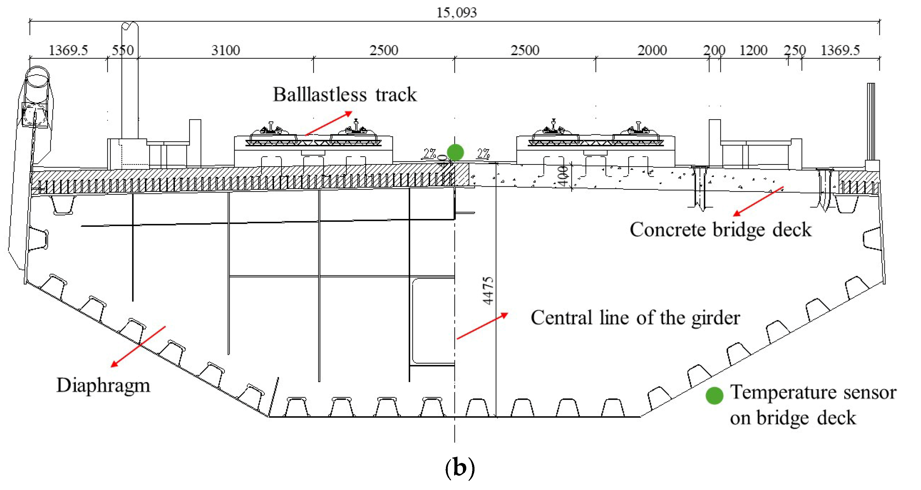
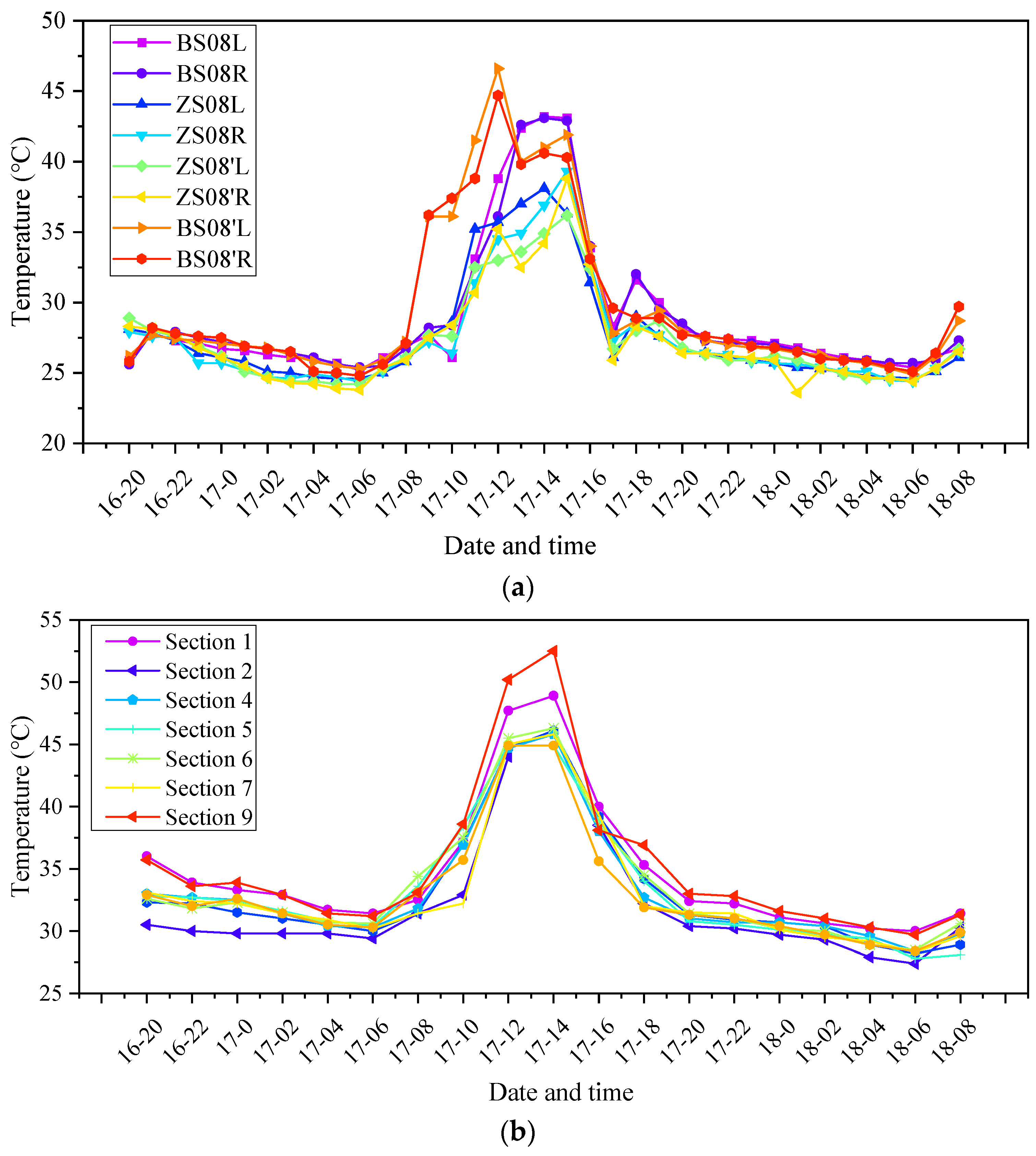
Temperature sensors were installed along the longitudinal direction of the composite girder of the cable-stayed bridge at critical locations. As shown in Figure 1a, the green markers indicate the positions of the temperature sensors on the main girder. Nine temperature monitoring sections (Sections 1–9) were arranged along the composite girder, with one temperature sensor mounted on the surface of the concrete deck slab at each composite girder section. The temperature sensors for the composite girder were installed on the surface of the concrete bridge deck, as illustrated in Figure 1b. In addition, temperature sensors were mounted on the outer surfaces of the sheathing of Cables No. 4, 8, and 12 on both sides of the bridge. In total, 24 temperature sensors (3 × 4 × 2) were installed on the cables across the bridge. Temperature monitoring was carried out from 2 August 2024 to 18 December 2024, with data recorded at hourly intervals. This monitoring period covers summer, autumn, and early winter, capturing significant daily and seasonal temperature variations and providing representative temperature data for evaluating thermal effects. Figure 2 presents the measured temperature histories of the concrete deck and the cables from 20:00 on 16 August to 08:00 on 18 August. During this period, the maximum recorded temperatures of the concrete deck and the cables were approximately 52 °C and 47 °C, respectively.

2.2. Integrated Finite Element Model of Ballastless Track–Bridge System

2.2.1. Numerical Modeling

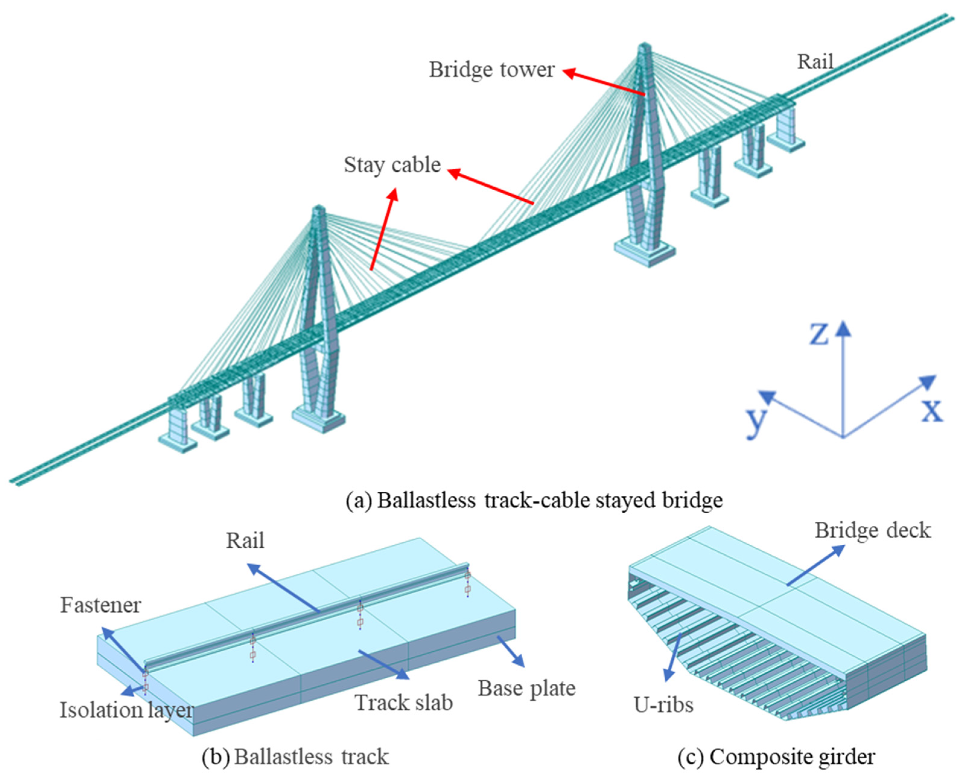
The integrated beam-track finite element model (FEM) of the Taiziping Wujiang River Bridge is shown in Figure 3, where the x-, y-, and z-axes correspond to the longitudinal, transverse, and vertical directions, respectively. The bridge is a twin-pylon cable-stayed structure with a main span arrangement of (130 + 300 + 130) m, adopting a semi-floating structural system. The side spans are constructed using cast-in-place concrete box girders, while the main span adopts a steel–concrete composite girder configuration.
The concrete box girders and the concrete deck of the composite girder are made of C55 concrete, whereas the pylons are constructed with C50 concrete. The steel components of the composite girders are mainly fabricated from Q345qD and Q345qE structural steel grades. The bridge deck is equipped with a double-block ballastless track system. The system consists of a base plate, track slab, rails, and a fastening system connecting the rails to the track slab. Both the base plate and the track slab are constructed using C40-grade concrete. Rails with a unit weight of 60 kg m−1 and WJ-8B constant-resistance fasteners are adopted. Table 1 lists the material properties adopted in the FEM, which were determined according to the specification (TB 10002.1-2017) [36]. The geometric nonlinearity of the stay cables was explicitly considered by modeling each cable as a series of straight truss elements, and large-displacement analysis was enabled to capture the nonlinear force–deformation relationship of the cables.
In the FEM, the structural components of the cable-stayed bridge, including the composite girder, pylons, and stay cables, as well as the components of the ballastless track system, including the base plate, track slab, and rails, were simulated using beam elements. Elastic support boundary conditions were applied at the piers and pylons. The interactions at the bottoms of the piers and pylons were represented by equivalent springs, with stiffness values defined in both translational and rotational directions. The steel–concrete interface of the composite girder was assumed to be rigidly connected. It should be noted that the rigid connection at the steel–concrete interface of the composite girder mainly affects local interfacial deformation. However, since temperature-induced global deformation is primarily governed by the overall structural stiffness, the influence of these simplifications on the global vertical deformation of the composite girder is limited.
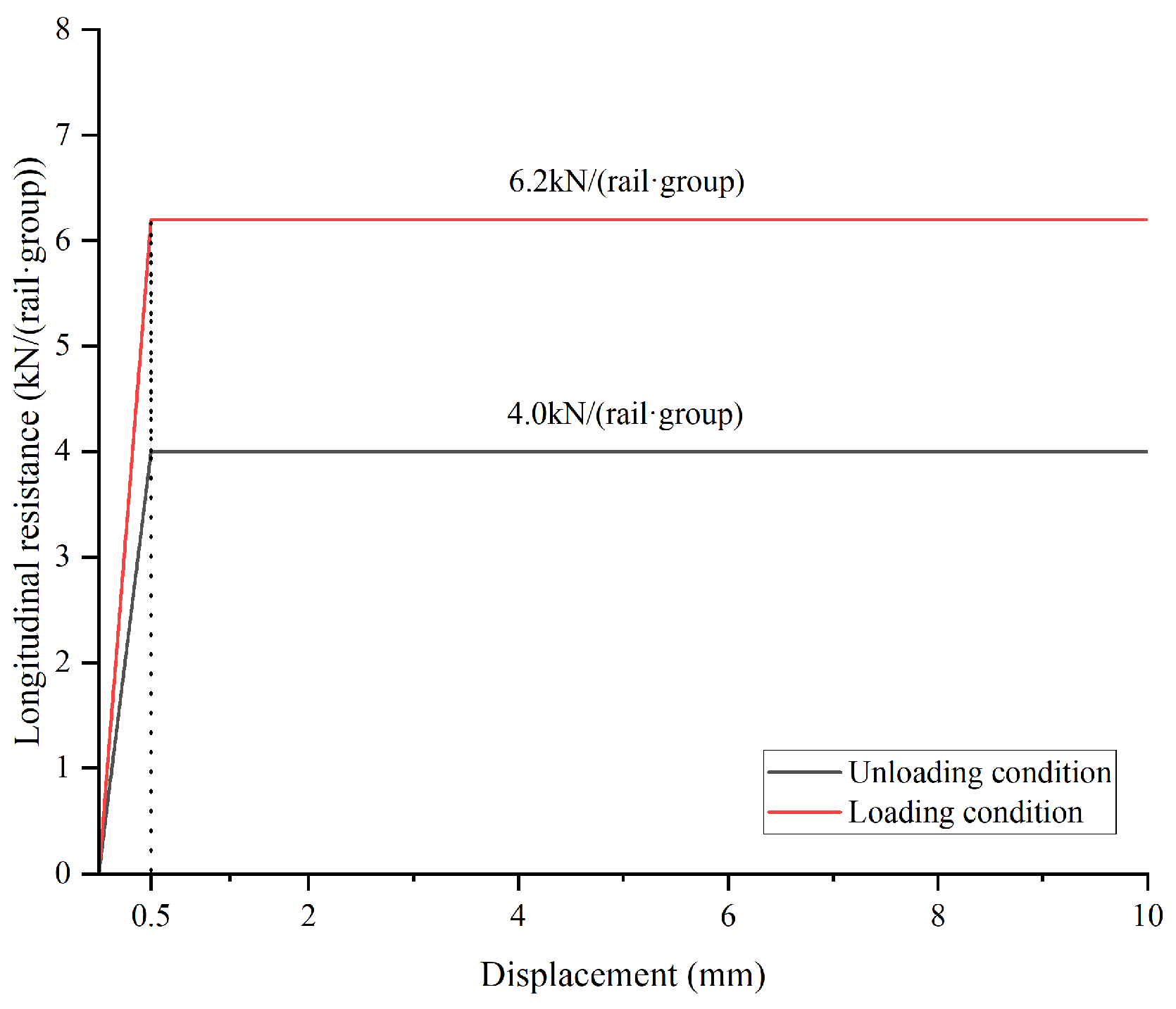
The steel box girder and the concrete deck are defined as independent beam elements sharing the same nodes, allowing the composite girder to be simulated through full coupling of the nodal degrees of freedom. To accurately simulate the boundary conditions and the longitudinal force transfer in the rails, 150 m long ballastless track extension sections were modeled on both sides of the bridge outside the bridge limits. The longitudinal resistance provided by the rail-track slab fasteners was represented using nonlinear spring elements. The nonlinear longitudinal resistance model of the rail fastener is illustrated by the unload condition in Figure 4, with an elastoplastic transition displacement of 0.5 mm. The loading sequence was also considered, with different constitutive relationships applied under loading and unloading conditions. The relationship corresponding to the loading condition is adopted when traffic loads are applied to the rail, whereas the relationship corresponding to the unloading condition is used when no traffic load is present. The vertical stiffness of the fastener system was modeled using linear spring elements with a stiffness of 150 kN/mm, corresponding to the WJ-8B fastener type, which is considerably higher than that adopted (35 kN/mm) in Ref. [29]. A rigid connection was adopted between the track slab and the base plate to represent perfect interfacial bonding in the double-block ballastless track system. Potential interfacial damage in the ballastless track, as well as shear-lag and other local effects, were not considered in this global FEM analysis, as this study focuses on the overall temperature-induced deformation of the girder–track system. In addition, the base plate and the bridge deck are cast integrally through pre-embedded anchor rebars; therefore, a rigid connection was also adopted between the base plate and the bridge deck.

2.2.2. Temperature Load Cases

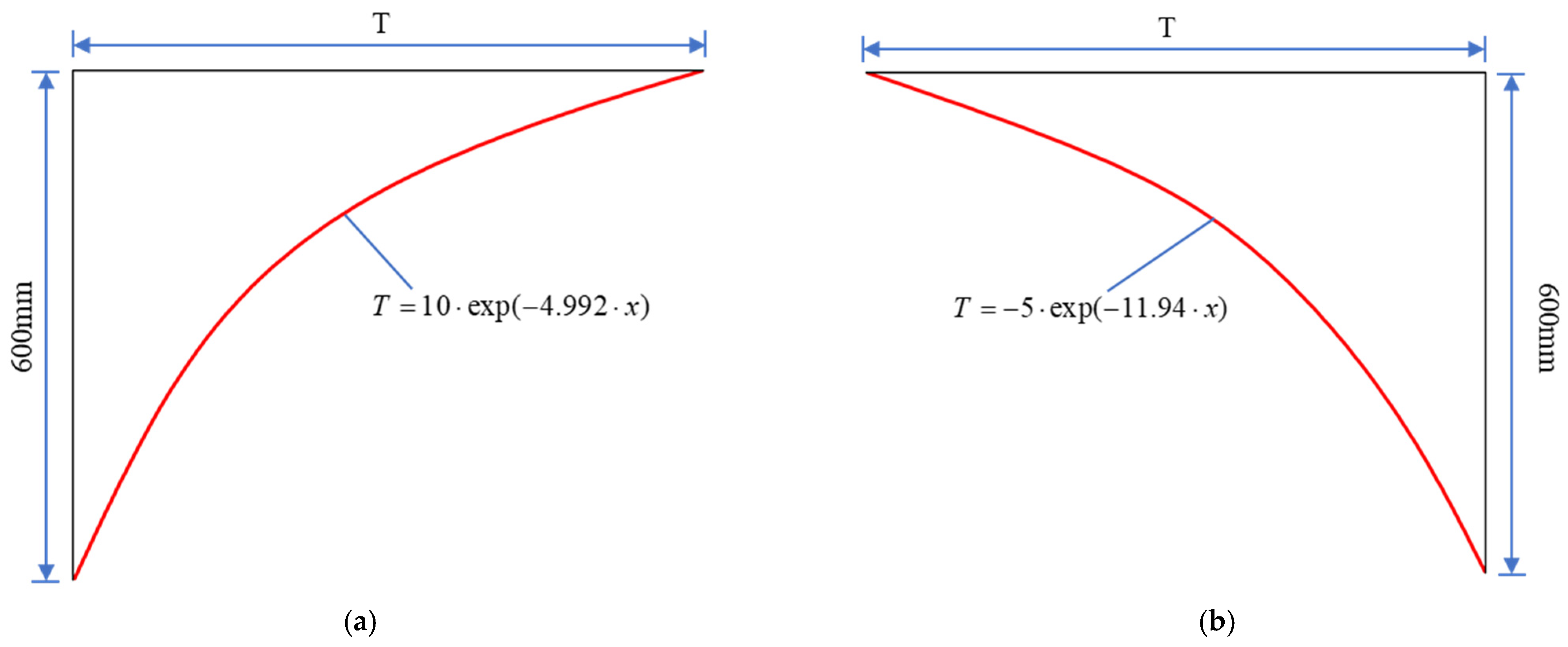
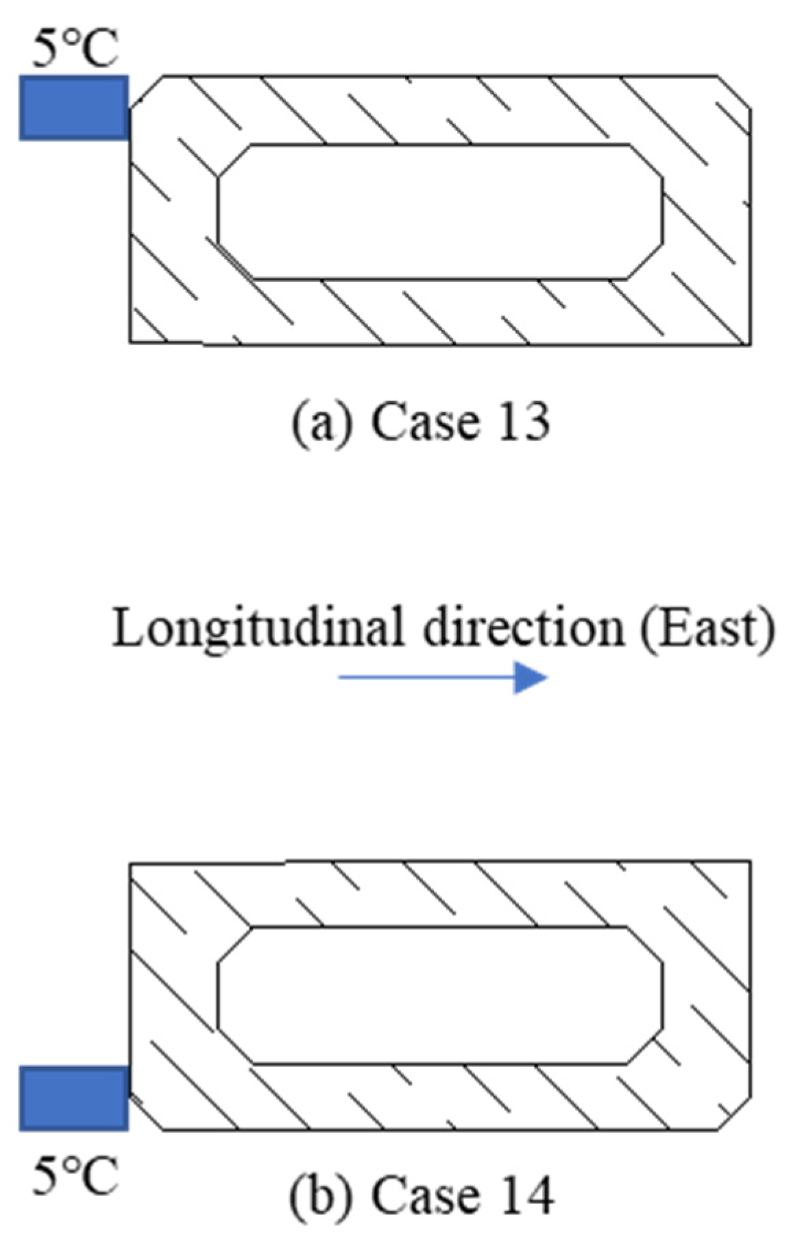
A total of 14 temperature load cases were considered to account for temperature differences among structural components of the cable-stayed bridge. The specific temperature variations were determined based on field-monitored temperature data and Chinese HSR code provisions. Table 2 summarizes the first ten temperature load cases. The reference temperature is set to 0 °C in the FEM. Load Cases 1 and 2 represent uniform temperature increases and decreases in the entire system, reflecting the effects of ambient temperature variations on the whole track–bridge system. Load Cases 3–10 correspond to temperature increases and decreases in one or two structural components, including the composite girder, pylons, and stay cables. In particular, Load Cases 5 and 6 represent different temperature variations in the concrete bridge deck and the steel box girder. Load Cases 11 and 12 represent nonlinear positive and negative temperature gradients of the concrete bridge deck, respectively. Since only the deck surface temperatures were measured at the girder sections, and the vertical temperature gradients through the girder depth were applied according to the Code for Design of Railway Bridges and Culverts (TB 10002.1-2017), these gradients were defined using exponential functions, as given in Equations (1) and (2) and illustrated in Figure 5.
T max ( x ) = 10 e 4.992 x
T min ( x ) = 5 e 11.94 x
where x denotes the vertical distance measured downward from the top surface of the concrete bridge deck, and Tmax(x) and Tmin(x) represent the maximum and minimum temperatures (unit: °C) at height x (unit: mm), respectively. As Figure 5 refers to the temperature gradients of the concrete bridge deck in the composite girder, the 600 mm dimension refers only to the height of the concrete bridge deck, and the track slab is not included. Load Cases 13 and 14 correspond to nonlinear positive and negative temperature gradients in the transverse direction of the pylons, as illustrated in Figure 6. The temperature variations can be considered through multiple thermal loading conditions, and these variations also serve as a proxy for climate-induced thermal effects on structural deformation.

3. Results and Discussion

3.1. Temperature Deformation of Composite Girder and Pylon

3.1.1. Comparison with the Theoretical Formulas

To verify the reliability of the established FEM, the calculated mid-span vertical displacements are compared with the simplified theoretical formulas proposed by Zhou et al. [37]. In their study, the mid-span deflection of the girder in a symmetrical twin-pylon cable-stayed bridge caused by temperature variations in the girder and cables can be estimated using Equations (3) and (4), respectively.
D T ( G ) = H 0 S 0 2 L 0 / 2 + α G Δ T G L 0 / 2 + γ 0 L 0 2
D T ( C ) = H 0 ( S 0 + α C Δ T C S 0 ) 2 L 0 / 2 + γ 0 L 0 ( S 1 + α C Δ T C S 1 ) 2 H 0 2 2
where D T ( G ) and D T ( C ) denote the mid-span deflection of the girder induced by the temperature change in the girder and the cable, respectively; L 0 and γ 0 L 0 denote the length of the main and side spans, respectively; H 0 and λ 0 H 0 represent the heights of the pylon above and below the girder, respectively; S 0 and S 1 denote the lengths of the side cables at the main span and side-span, respectively; and α C and α G represent he thermal expansion coefficients of the cable and girder materials, respectively.
Table 3 compares the theoretical values calculated using the general simplified formulas with the FEM results under Cases 3, 4, 9, and 10. Cases 3 and 4 represent the structural responses to girder temperature variations of +5.7 °C and −9.1 °C, respectively, while Cases 9 and 10 correspond to cable temperature variations of +10 °C and −10 °C, respectively. As shown in Table 3, the displacement directions (signs of vertical movement) predicted by the simplified theoretical formulas are consistent with the FEM results in all cases, indicating that both approaches capture the same fundamental thermal deformation mechanism of the composite cable-stayed bridge.
The relative errors between the theoretical and FEM results are approximately 73% for girder temperature-induced displacement and 27% for cable temperature-induced displacement. The relatively large discrepancies mainly arise from the simplifying assumptions adopted in the general theoretical formulas. In Zhou et al. [37], the cable system is simplified by considering only the longest stay cables in the main and side spans, which connect the pylon top to the girder end or mid-span, and the flexural rigidity of the girder and pylons is neglected. In addition, the stiffness contribution of the ballastless track system as well as the nonlinearity of the cables are not considered in the simplified formulation. These assumptions significantly reduce the structural complexity and inevitably lead to deviations from the actual structural behavior. Therefore, the comparison demonstrates that the FEM results are consistent with theoretical predictions in terms of the deformation mechanism while providing more accurate displacement magnitudes.

3.1.2. Temperature-Induced Deformation

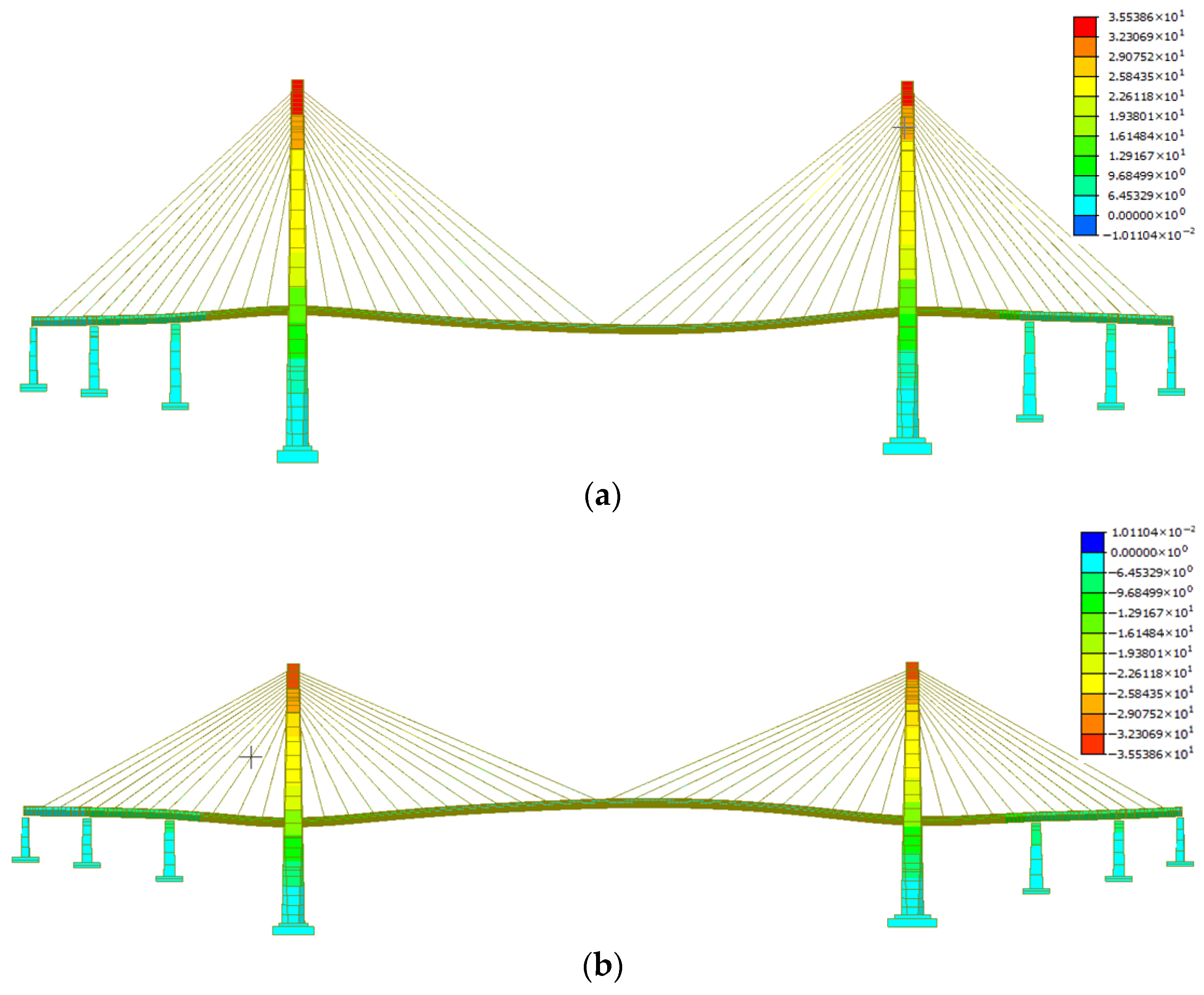
The maximum temperature-induced deformations calculated under the 14 temperature load cases are summarized in Table 4. For the uniform temperature increase and decrease of 22.4 °C (Cases 1 and 2), the FEM simulated deflections are presented in Figure 7. Under Case 1, the top of the pylon rises by 36.0 mm, and the composite girder expands by 66.9 mm in the longitudinal direction at both ends. Conversely, under Case 2, the top of the pylon contracts downward and the composite girder contracts inward at the longitudinal ends. At the middle of the central span, the composite girder deflects only 1.5 mm downward under Case 1 and arches upward under Case 2. Generally, uniform temperature changes primarily influence the vertical deformation of the pylons and the longitudinal deformation of the composite girder.
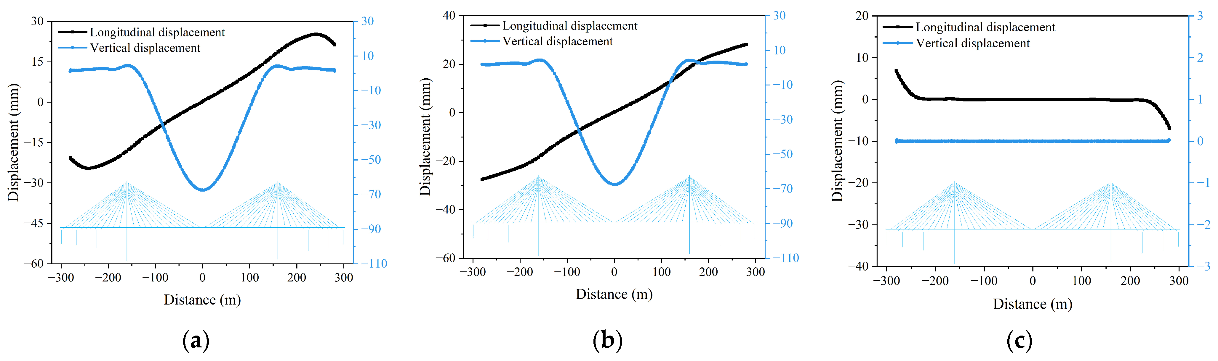
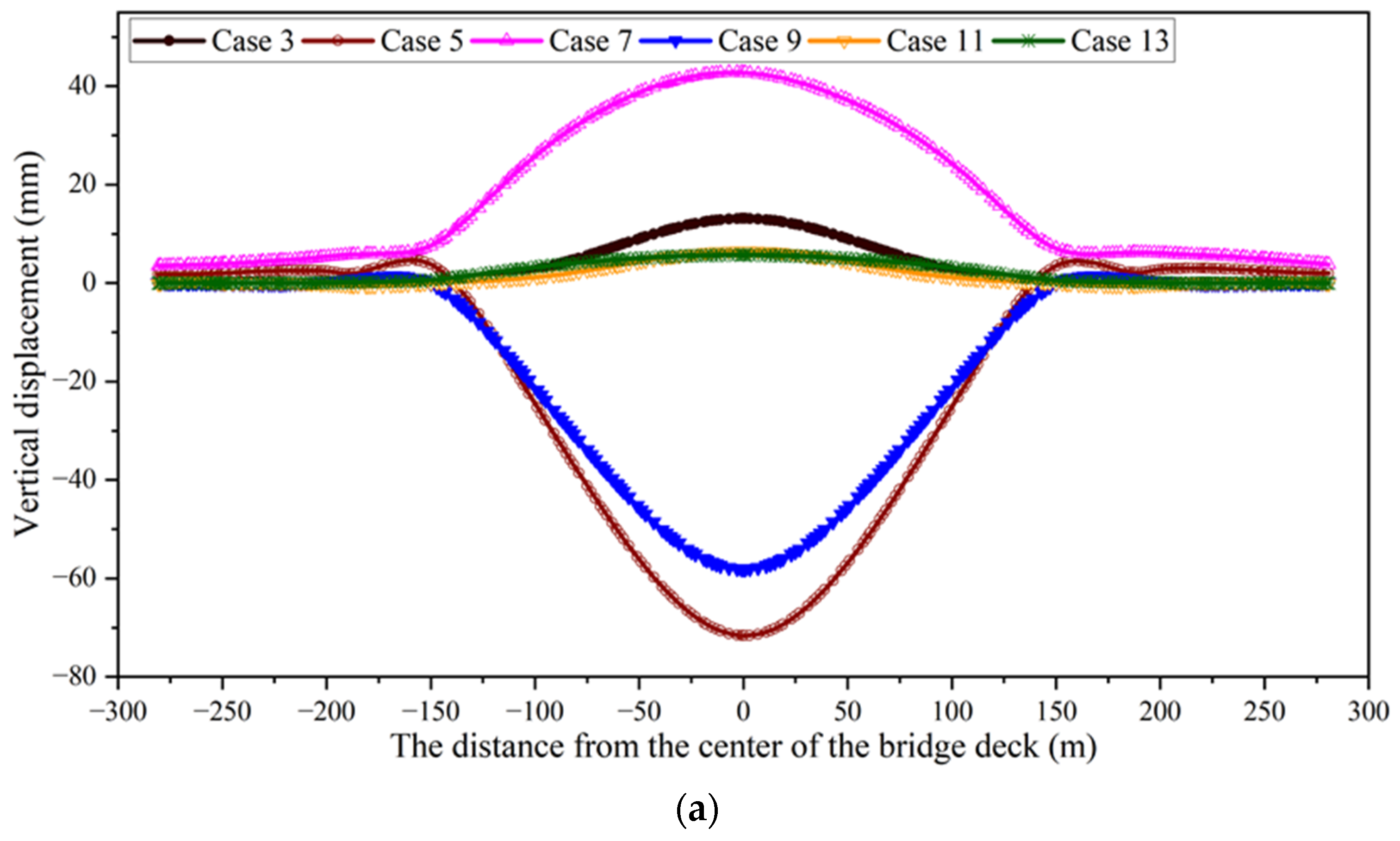
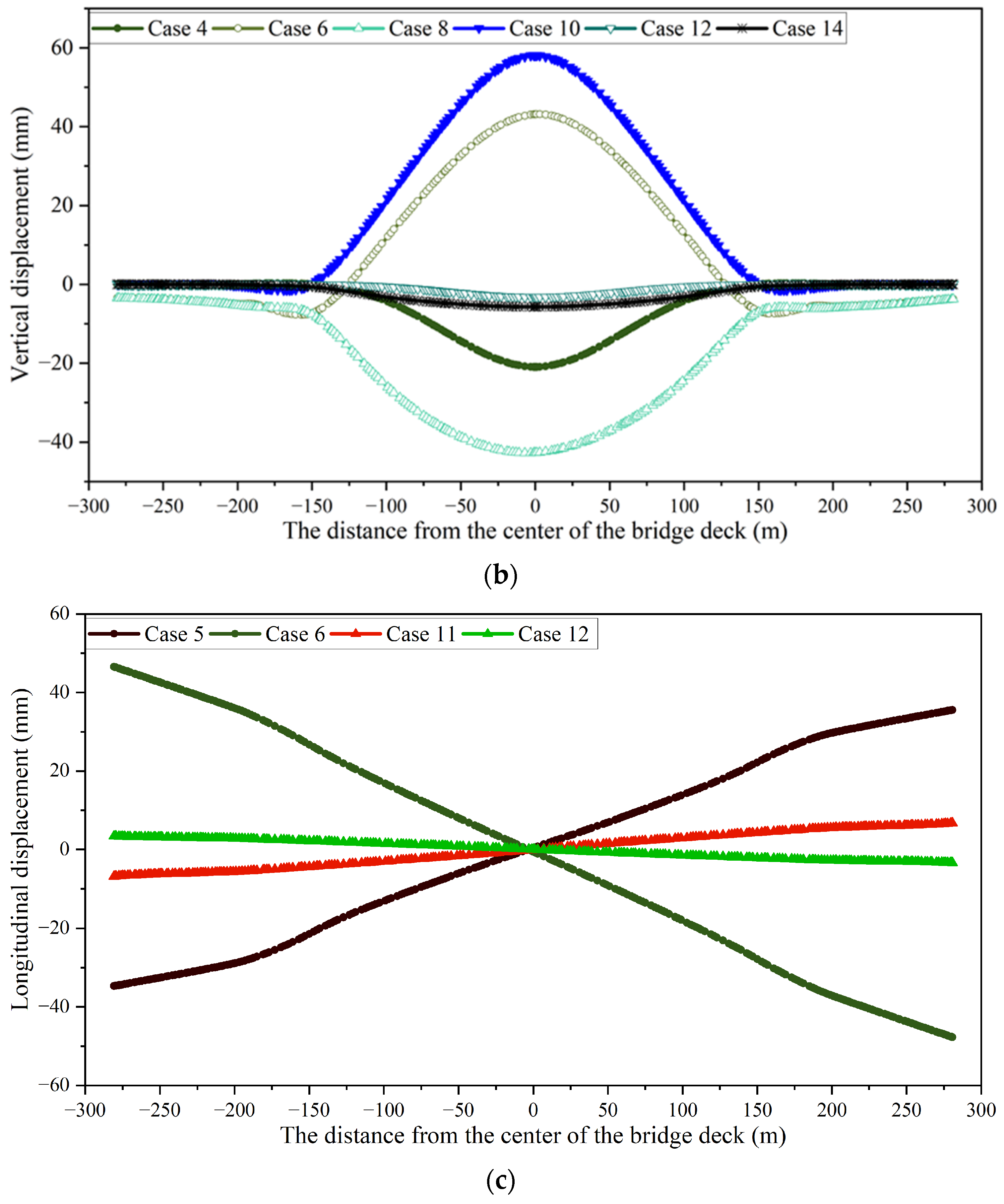
The vertical displacement distributions of the composite girder under temperature Load Cases 3–14 are shown in Figure 8a,b. Figure 8a presents the temperature-rise scenario (i.e., Cases 3, 5, 7, 9, 11, and 13), while Figure 8b corresponds to the temperature- decrease scenario (i.e., Cases 4, 6, 8, 10, 12, and 14). In the side spans of the cable-stayed bridge (−300 m to −150 m and 150 m to 300 m), the vertical displacement of the composite girder remains minimal under all temperature load cases. The displacement increases progressively toward the pylons, with noticeable deformation occurring near the −150 m and 150 m locations, and reaches its maximum at the middle of the central span.
Under Case 3 (a temperature increase of 5.7 °C in the composite girder), the maximum upward deformation at mid-span is 13 mm. Under Case 4 (a temperature decrease of 9.1 °C in the composite girder), the mid-span deflection reaches −21 mm. Under Case 5 (temperature increases of 7 °C in the concrete deck and 22.4 °C in the steel box girder), the composite girder deflects downward by −71.6 mm. Under Case 6 (temperature decreases of 13 °C in the concrete deck and 22.4 °C in the steel box girder), the girder arches upward by 43.1 mm at mid-span. Under a ±15 °C pylon temperature change (Cases 7 and 8), the composite girder exhibits ±42.8 mm mid-span deformation, and the pylon undergoes ±22.6 mm vertical displacement. In Cases 9 and 10 (±9 °C cable temperature change), the composite girder deforms ±58 mm at mid-span. Under Cases 11 and 12 (nonlinear positive and negative deck temperature gradients), the girder exhibits +6 mm upward arching and −3.5 mm downward deflection, respectively. When the pylons are subjected to nonlinear positive and negative transverse temperature gradients (Cases 13 and 14), the composite girder arches upward by approximately 5.7 mm and deflects downward by −3.5 mm at mid-span.
Figure 8c presents the longitudinal deformation of the composite girder, which is primarily driven by temperature variations within the girder itself. The maximum longitudinal deformations occur in Cases 5–6 and 11–12, where the steel box girder or the concrete deck has a significant temperature change. Specifically, under Case 5, the ends of the composite girder elongate by approximately 35 mm, whereas under Case 6 they contract by about 47 mm. The maximum longitudinal deformations under Cases 11 and 12 are 7 mm and 3.5 mm, respectively. The other temperature load cases produce negligible longitudinal deformation and are therefore not shown in Figure 8c.
In the present study, the analysis primarily focused on temperature-induced vertical and longitudinal deformation responses of the integrated bridge–track system. Rotational responses of the girder, particularly at the beam ends and pylon–girder connections, were not explicitly evaluated. It is acknowledged that girder rotations may have important implications for continuously welded rail systems, as excessive rotations can affect rail alignment, induce additional bending stresses, and influence serviceability performance. Therefore, a comprehensive assessment of rotational behavior and its compliance with relevant code-specified allowable limits is valuable to be conducted in future research to further refine the evaluation of bridge–track interaction under thermal loading conditions.

3.1.3. Temperature Sensitivity Coefficients

Temperature variations in the composite girder, pylons, and cables have the most significant influence on the vertical displacement of the composite girder. Therefore, these three temperature loads were linearly increased to examine their effects on the maximum mid-span deformation (upward arching and downward deflection) of the composite girder.
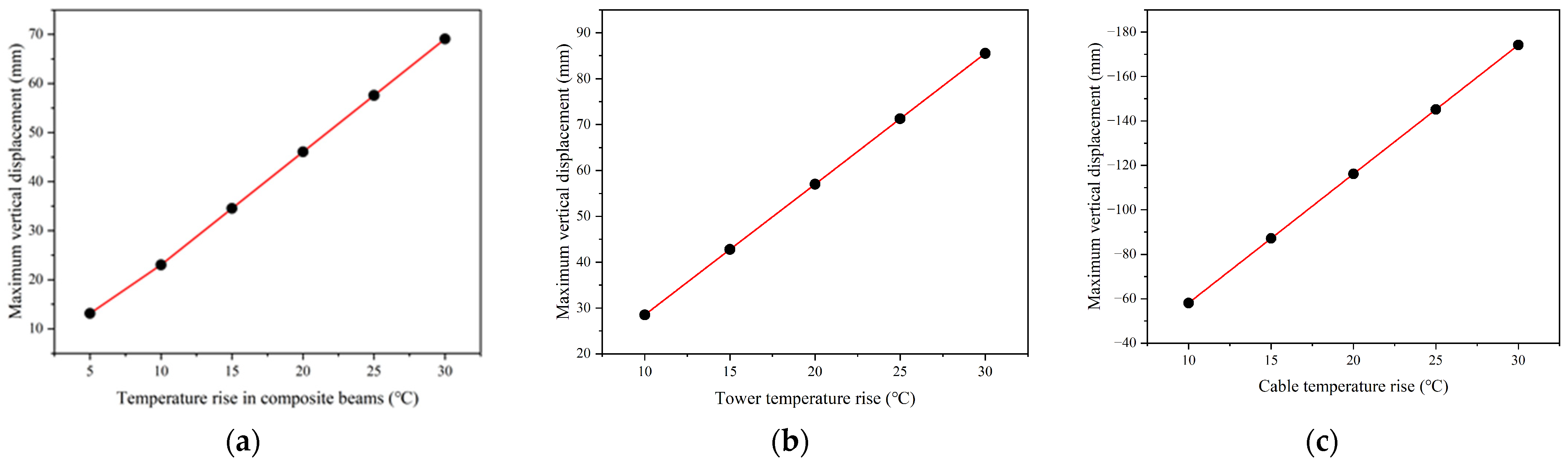
The maximum deflections of the composite girder under temperature increases of 10 °C, 15 °C, 20 °C, 25 °C, and 30 °C applied to the composite girder, pylon, and cable are shown in Figure 9a, b, and c, respectively. The maximum vertical displacement is linearly proportional to the temperature increase in each structural component. Accordingly, the temperature sensitivity coefficients ki, defined in Equation (5), were evaluated to quantify the influence of each temperature load on the maximum vertical displacement of the composite girder.
k i = D max Δ T i   ( i = 1 ,   2 ,   3 )
where ki denotes the temperature sensitivity coefficients, Dmax denotes the maximum vertical displacement of the composite girder, ΔTi represents the temperature change in the structural component, and i corresponds to the girder, pylon, and cable, respectively. In this study, corresponding to the temperature change in the composite girder, pylon, and cable, the temperature sensitivity coefficients were calculated as 2.3 mm/°C, 2.78 mm/°C, and −5.8 mm/°C, respectively. Since these coefficients primarily depend on structural stiffness, span arrangement, and material properties, the proposed parameterized relationship can be applied to other long-span composite girder cable-stayed bridges with similar structural characteristics for temperature-induced deformation evaluation.

3.2. Temperature Deformation of Ballastless Track

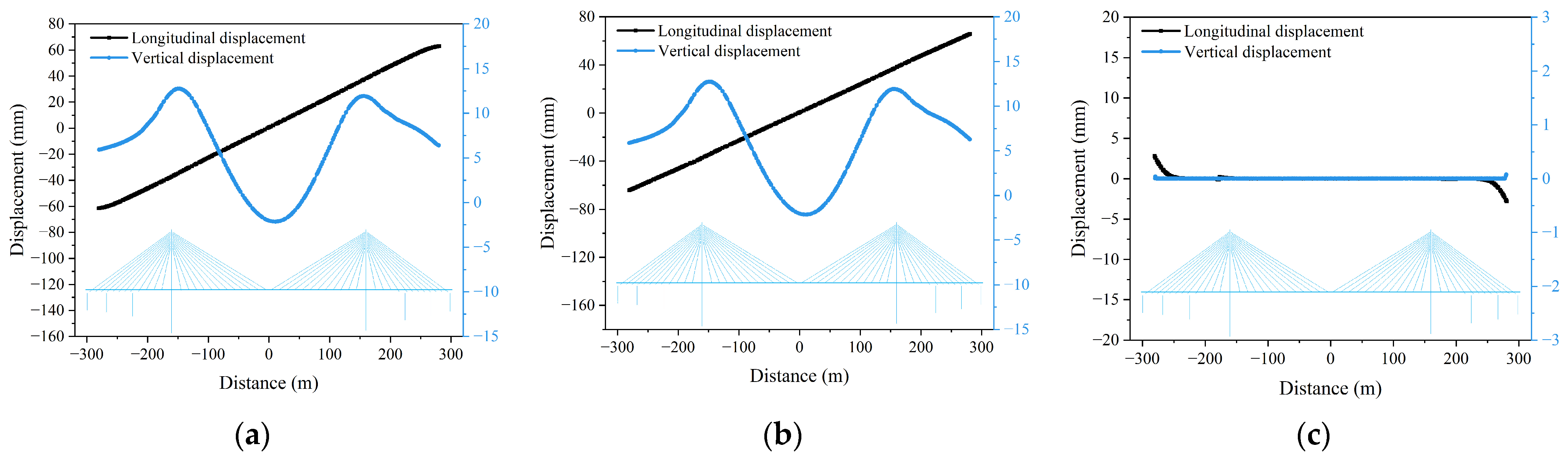
Because the structural deformations under temperature increase and decrease are symmetrical in magnitude but opposite in direction, only the temperature-rise load cases were considered in this part. Figure 10 illustrates the displacements of the track slab and rails, as well as their relative displacements, under the uniform temperature increase condition (Case 1). The rails and track slab exhibit a maximum upward deformation of approximately 13 mm near the pylons and a maximum downward deflection of about 3 mm at the mid-span of the composite girder. The vertical deformation profiles of the rail and track slab almost coincide along the entire span, indicating strong vertical compatibility and no separation between the two components. Owing to the boundary conditions of the cable-stayed bridge, the longitudinal relative displacement between the rails and track slab is mainly concentrated at one end of the bridge, where it reaches a maximum value of approximately 2.5 mm. According to UIC Code 774-3R [38], the maximum allowable longitudinal relative displacement between the rails and the track slab at bridge ends is 5 mm. When rail expansion devices are installed in continuous welded rails, the allowable absolute longitudinal displacement is 30 mm to ensure operational safety. For the studied bridge, the expansion devices are concentrated at the bridge ends within a range of 19.7 m. Under Case 1, the calculated relative displacement remains within the specified safety limits. This concentration near the bridge end suggests that sliding between the rail and track slab is most likely to initiate in this region, where longitudinal restraint is relatively weak and cumulative thermal expansion of the girder is released.
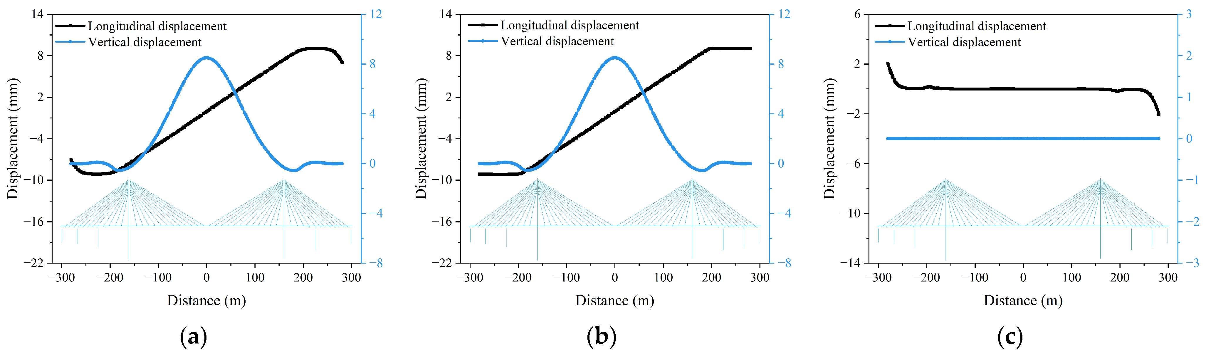
Under Case 3, the rails and track slabs exhibit a maximum downward deflection of approximately 1 mm near the two pylons, as shown in Figure 11a,b. In contrast, they show a maximum upward deformation of about 9 mm at the mid-span of the composite girder. The longitudinal displacement of both components increases outward toward the bridge ends, reaching approximately 9 mm. The longitudinal relative displacement between the rails and track slabs attains a maximum of about 2 mm at the bridge ends, as shown in Figure 11c. Similar to Case 1, the relative displacement is primarily localized at the expansion regions near the abutments, indicating that potential rail–slab sliding would be expected at the bridge ends rather than in the central span, where longitudinal deformation remains largely compatible.
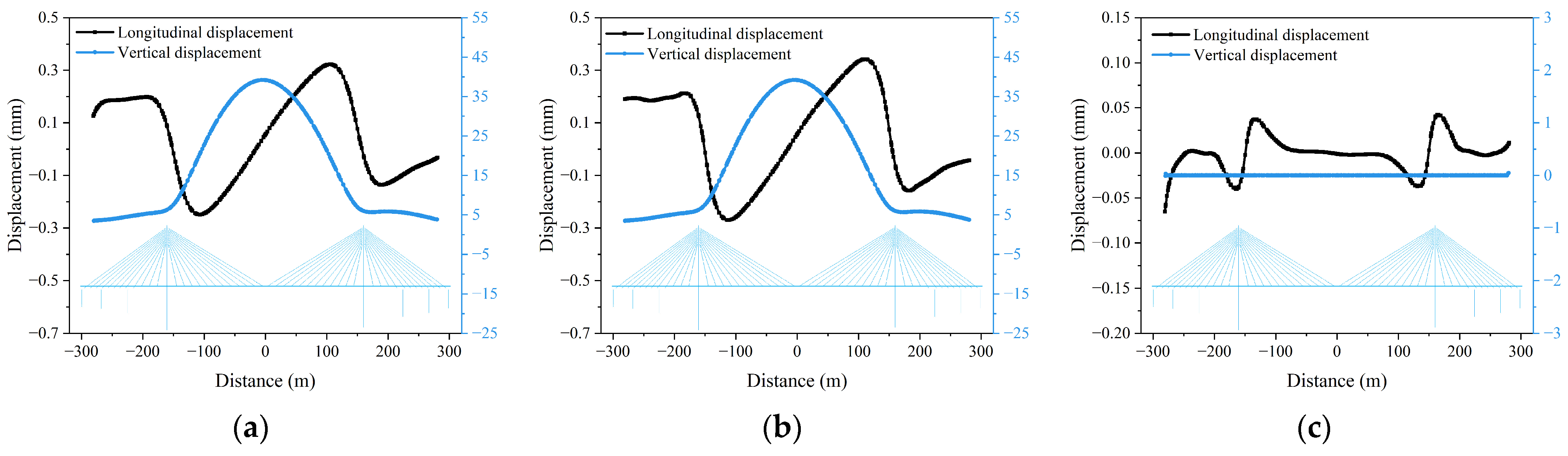
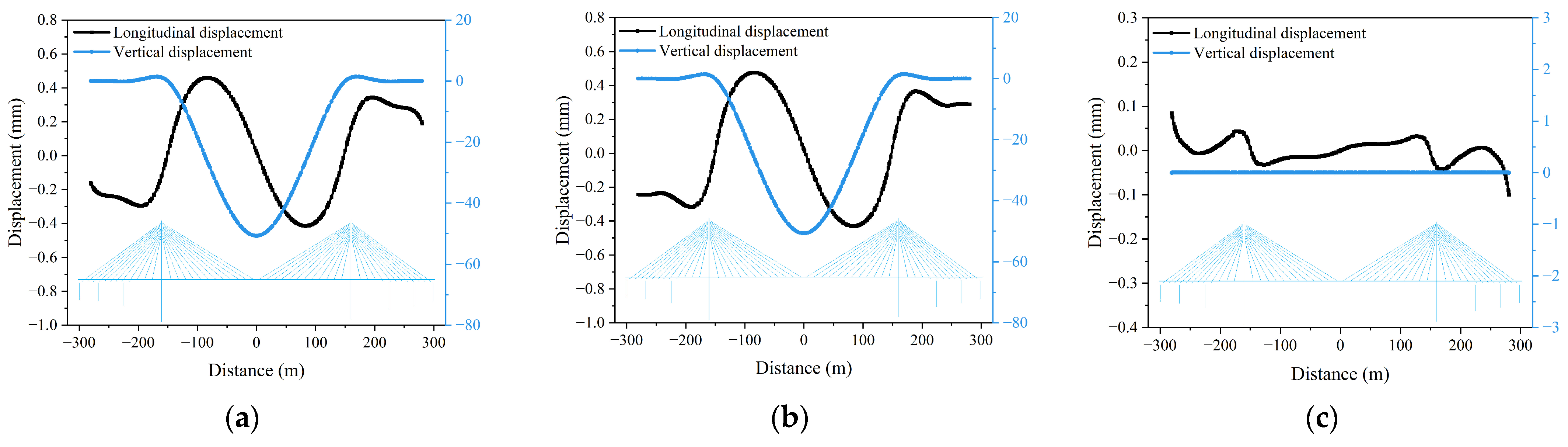
In Case 7, the rails and track slabs exhibit a maximum upward deformation of approximately 40 mm at the mid-span of the composite girder (Figure 12a,b). Unlike Cases 1 and 3, no downward deflection occurs anywhere along the bridge. The temperature change in the pylon has minimal influence on the longitudinal displacement, and the longitudinal relative displacement between the rails and track slabs is negligible, not exceeding 0.1 mm (Figure 12c). This negligible relative displacement indicates that sliding between the rail and track slab is unlikely under this temperature scenario, as the longitudinal deformation of both components remains nearly fully coordinated. Case 9 results in a maximum downward deflection of approximately 50 mm at the mid-span of the main girder (see Figure 13a,b). The impact of the temperature change in the cable on the longitudinal displacement of the bridge structures is minimal, as shown in Figure 13c. Accordingly, the longitudinal relative displacement between the rail and track slab remains very small, implying a low probability of sliding in this case.
When the temperatures of the concrete deck and steel box girder increase by 7 °C and 22.4 °C, respectively (Case 5), the rails and track slab experience the largest downward deflection among the analyzed cases, approximately 70 mm at mid-span (Figure 14a,b). The maximum allowable vertical irregularity of a ballastless track is 7 mm within a 60 m chord length according to the Chinese track standard [39]. Under Case 5, although the maximum rail vertical deflection reaches approximately 70 mm at mid-span, the corresponding vertical unevenness (track alignment irregularity) is only about 1.2 mm and occurs near the pylons, which is well within the allowable tolerance.
The relative longitudinal displacement between the rails and track slab is concentrated near the bridge ends, reaching a maximum of about 7 mm (Figure 14c). Nevertheless, the relative displacement also meets the requirements. Across all temperature scenarios, the vertical displacements of the rails and track slab remain fully consistent, indicating no vertical relative movement between the two components. These results highlight that temperature variation is a key factor influencing rail deformation. Therefore, special attention should be given to the arrangement of rail expansion devices, seasonal temperature monitoring, and deformation inspection in these critical regions.

3.3. Prediction of Temperature Deflection of Composite Girder

3.3.1. Relationship Between Ambient Temperature and Structural Temperature

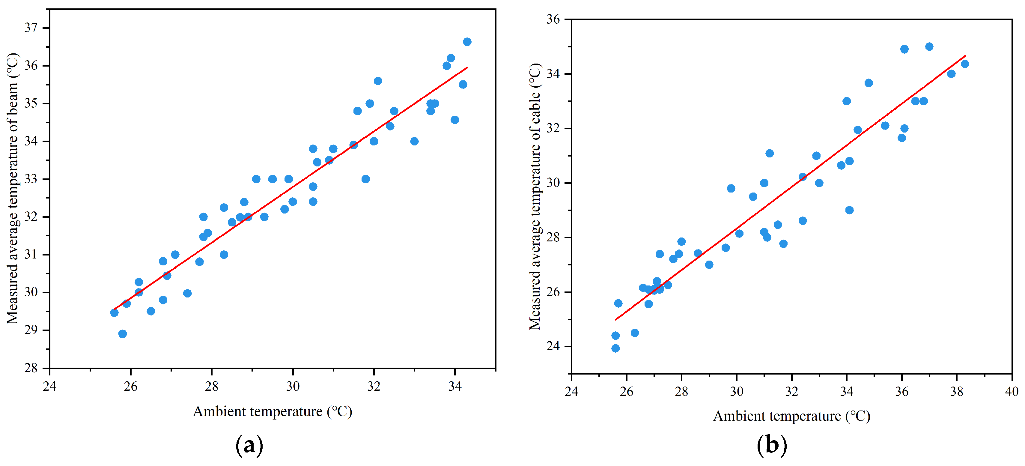
In this part, the relationship between the monitored temperatures of the composite girder and cables and the corresponding ambient temperature is established, as shown in Figure 15. For each time step, the composite girder temperature is taken as the average of all girder measuring points, while the cable temperature is computed as the average of all cable measuring points. The horizontal axis in Figure 15 denotes the ambient temperature, and the vertical axis represents the temperatures of the composite girder and cables. By fitting these data, a direct correlation is obtained, enabling estimation of structural temperatures from ambient temperature. Despite the limited monitoring duration, the temperatures monitored in August and December exhibit representative characteristics of summer and winter thermal conditions, respectively, allowing the established relationships to capture the seasonal thermal responses of the cables and the girder. The resulting fitted relationships are given in Equations (6) and (7).
T g = 0.74 T a + 10.72
T c = 0.763 T a + 5.51
where Tg denotes the temperature of the composite girder, Tc represents the temperature of the cable, and Ta represents the ambient temperature in the bridge site. The coefficients of determination (R2) for the two predictive formulas are 0.91 and 0.89, respectively, indicating that Equations (4) and (5) accurately capture the relationship between the structural temperatures and the ambient temperature.

3.3.2. Prediction of Composite Girder’s Vertical Displacement

(1)
Prediction of vertical displacement caused by the temperature change in composite girder
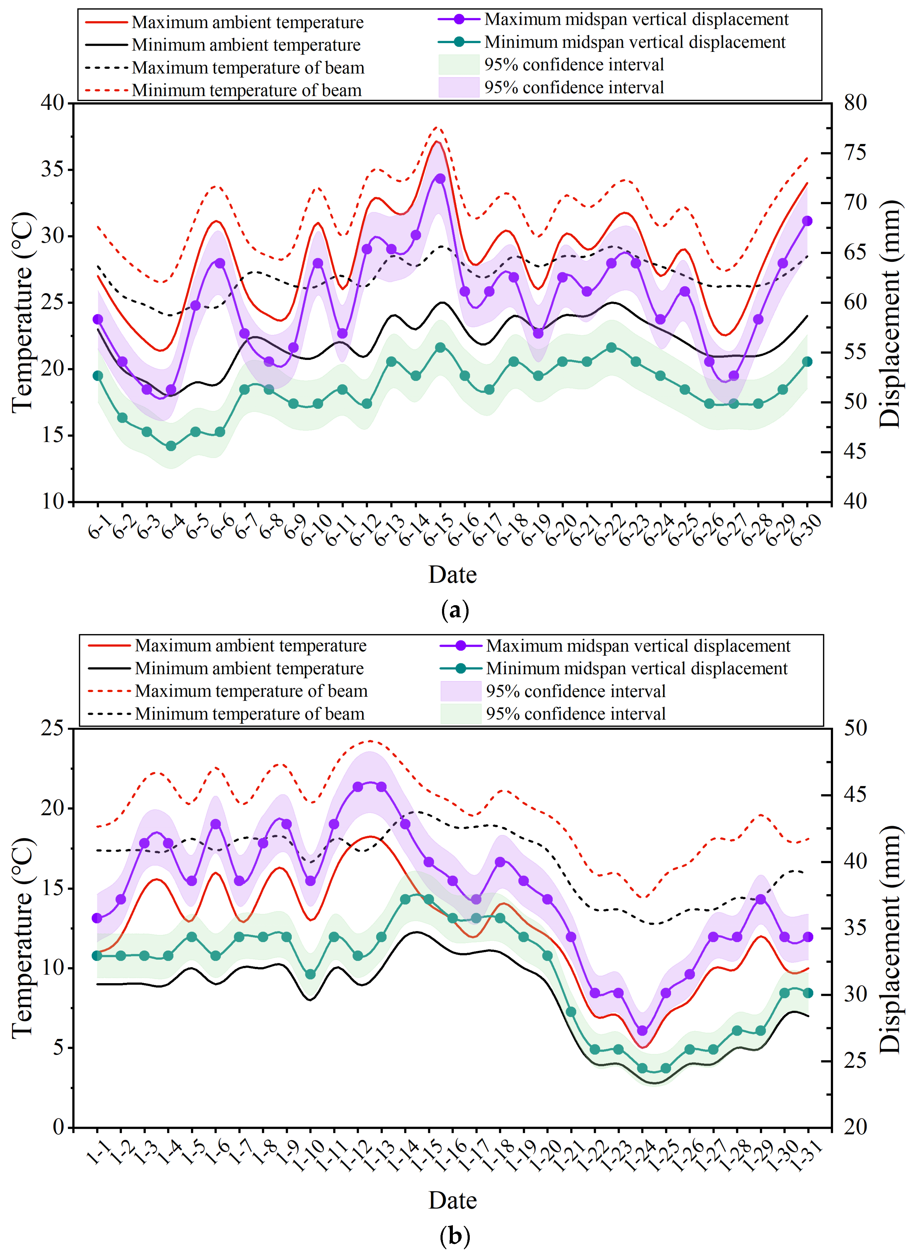
The obtained relationships (i.e., Equations (4) and (5)) were used to estimate the girder temperatures based on ambient temperature records provided by the local meteorological station (the official meteorological station of Wulong District, Chongqing, China) at the case-study bridge. June typically records the highest ambient temperatures of the year at the bridge site. Accordingly, ambient temperature data for June 2024 were collected from the meteorological station. Using these records, the structural temperatures in June 2024 were extrapolated using the fitted relationships. Using the estimated girder temperatures in June 2024 and the established FEM, the resulting time series of the girder’s vertical displacement at mid-span as well as the temperatures are shown in Figure 16a. It should be noted that, in this section, the temperature variations of the composite girder and cables were analyzed separately to quantify their individual contributions to the bridge’s vertical displacement. The predicted deformation magnitudes therefore represent isolated parametric effects rather than realistic simultaneous temperature actions under actual operating conditions. This analysis strategy was adopted to clarify the sensitivity of the system to each component’s temperature variation and should not be interpreted as representing a single real service scenario.
On 15 June, the maximum ambient temperature reached 37 °C, corresponding to a composite girder temperature of 38.1 °C. The girder consequently exhibited a maximum upward deformation of approximately 72 mm. By contrast, on 5 June, the minimum ambient temperature was 18 °C and the girder temperature was 24 °C, producing an upward deformation of about 45 mm.
January generally experiences the lowest ambient temperatures at the bridge site, and the measured temperatures during January were also used for analysis. Then, the composite girder’s temperature in January 2025 was obtained using Equation (4), and the mid-span vertical displacement of the composite girder was calculated based on the FEM, as shown in Figure 16b. On 12–13 January, the ambient temperature reached its monthly maximum of 18 °C, corresponding to a composite girder temperature of 24 °C and a resulting maximum vertical displacement of 45.6 mm. In contrast, on 24–25 January, the ambient temperature dropped to 3 °C, yielding a girder temperature of approximately 13 °C and a minimum vertical displacement of 24 mm.
(2)
Prediction of vertical displacement caused by the temperature change in cables
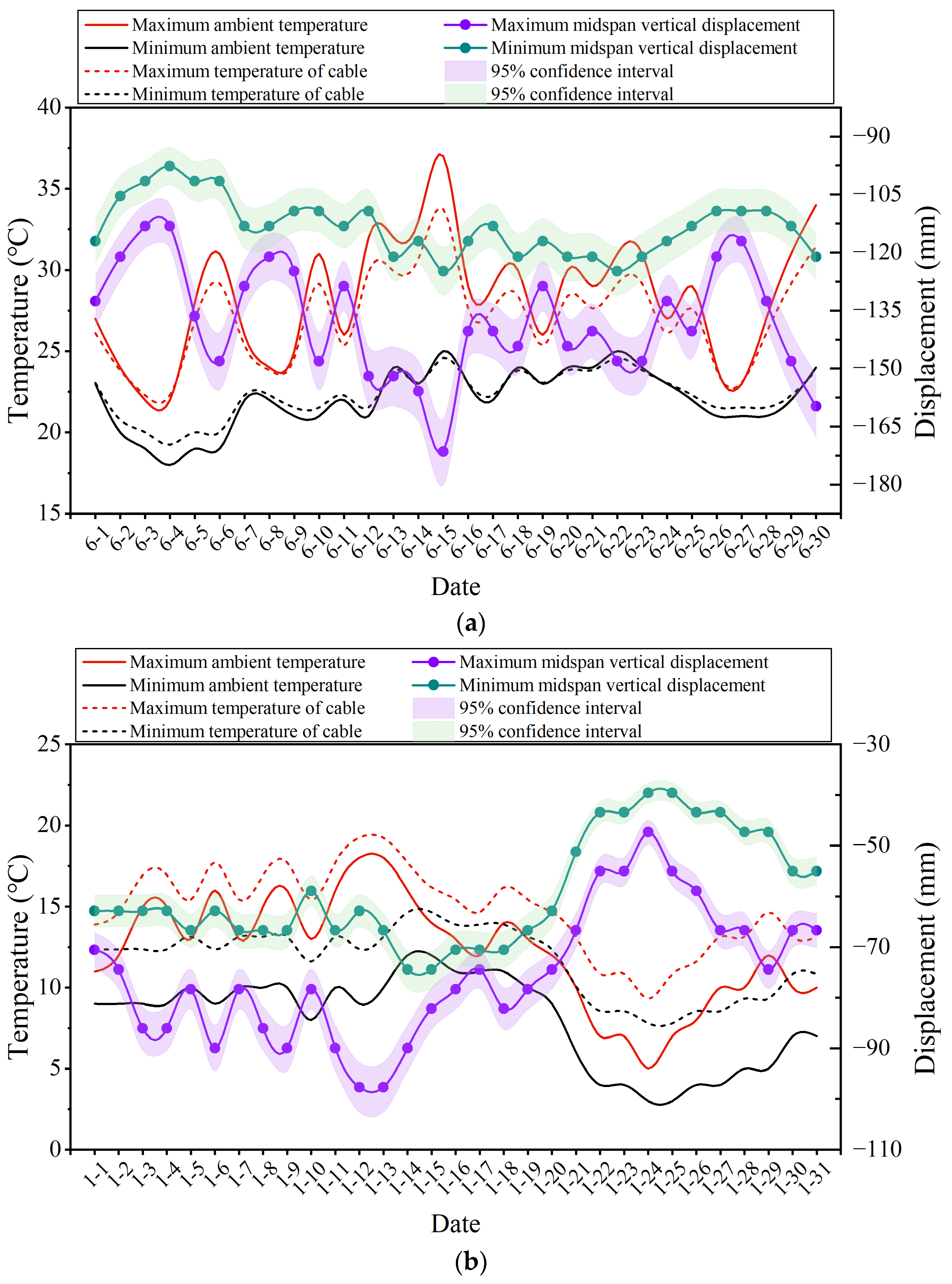
The cable temperatures in June 2024 and January 2025 were obtained by combining the recorded ambient temperatures with Equation (5). The resulting mid-span vertical displacement of the composite girder due to cable temperature variation was then evaluated using the FEM, as shown in Figure 17a. On 15 June, when the ambient temperature reached its monthly maximum of 37 °C, the corresponding cable temperature was 33.7 °C, producing a maximum mid-span downward deflection of 171 mm. In contrast, on 4 June, the ambient temperature was 18 °C, yielding a cable temperature of about 19 °C and a minimum mid-span displacement of 97.6 mm.
As shown in Figure 17b, on 12–13 January the ambient temperature reached its monthly maximum of 18 °C, corresponding to a cable temperature of 19 °C. The resulting maximum mid-span vertical deflection of the composite girder was 97.7 mm. In contrast, on 24–25 January the ambient temperature dropped to 3 °C, yielding a cable temperature of about 7.8 °C and a minimum mid-span deflection of 39.6 mm.

4. Conclusions

Based on the Taiziping Wujiang River Bridge in Chongqing, China, this study develops a refined and fully integrated FEM of a composite girder cable-stayed bridge with a ballastless track system. The effects of various temperature loading scenarios on the deformation behavior of the composite girder as well as the ballastless track are systematically investigated. Using monitoring data, a correlation model between ambient temperature and structural temperatures is established. On this basis, the temperature-induced deformation of the girder at specific times is predicted from ambient temperature variations. The main conclusions are summarized as follows:
  • Temperature variations in the girder, cables, and pylons have a significant influence on the vertical deformation of the girder. The mid-span vertical displacement of the composite girder generally shows an approximately linear relationship with temperature variations in key structural components, and the structural response can be characterized using temperature sensitivity coefficients. For the studied bridge, the corresponding temperature sensitivity coefficients are 2.3 mm/°C for girder temperature variation, 2.78 mm/°C for pylon temperature variation, and −5.8 mm/°C for cable temperature variation. This linear relationship provides a general framework for evaluating temperature-induced deformation in similar long-span composite cable-stayed bridges;
  • Under all temperature loading scenarios, the vertical displacements of the rails and track slab remain fully consistent. The temperature variation in the composite girder induces a relatively large longitudinal displacement between the rails and track slab, and the relative displacement is primarily concentrated near the bridge ends;
  • Using monitored temperature data, strong correlations between the ambient temperature and the measured temperatures of the composite girder and cables are established, with R2 values of 0.91 and 0.89, respectively. Based on these relationships, the temperature-induced deformation of the composite girder in summer and in winter is predicted from ambient temperature variations. In June 2024, temperature changes in the composite girder were estimated to induce a maximum mid-span upward deformation of 72 mm, whereas temperature variations in the cables resulted in a maximum mid-span deflection of 171 mm.
In this study, the temperature variations in the composite girder and cables of the bridge are analyzed separately to isolate and assess their individual effects on the vertical displacements in the girder. It should be noted that these temperature variations act simultaneously, and their combined effects would be more relevant for evaluating the overall performance of the track system, which is therefore suggested as a topic for future work.

Author Contributions

Conceptualization, Z.Z. and M.S.; Methodology, C.L.; Software, H.W.; Validation, J.C. and Z.Z.; Formal Analysis, D.W.; Investigation, D.W., J.C., C.L. and P.L.; Resources, J.C. and H.W.; Data Curation, H.W.; Writing—Original Draft, D.W., M.S. and P.L.; Writing—Review and Editing, M.S. and P.L.; Visualization, C.L.; Supervision, Z.Z. All authors have read and agreed to the published version of the manuscript.

Funding

This research received no external funding.

Data Availability Statement

The data presented in this study are available on request from the corresponding authors.

Conflicts of Interest

Authors Jiayuan Cheng and Hui Wan was employed by the company China Railway Major Bridge Engineering Group Co., Ltd. The remaining authors declare that the research was conducted in the absence of any commercial or financial relationships that could be construed as a potential conflict of interest.

References

  1. Su, M.; Dai, G.; Marx, S.; Liu, W.; Zhang, S. A Brief Review of Developments and Challenges for High-speed Rail Bridges in China and Germany. Struct. Eng. Int. 2019, 29, 160–166. [Google Scholar] [CrossRef]
  2. Su, M.; Dai, G.; Peng, H. Bond-slip constitutive model of concrete to cement-asphalt mortar interface for slab track structure. Struct. Eng. Mech. 2020, 74, 589–600. [Google Scholar] [CrossRef]
  3. Mao, J.X.; Wang, H.; Feng, D.M.; Tao, T.Y.; Zheng, W.Z. Investigation of dynamic properties of long-span cable-stayed bridges based on one-year monitoring data under normal operating condition. Struct. Control. Health Monit. 2018, 25, e2146. [Google Scholar] [CrossRef]
  4. Mao, J.X.; Wang, H.; Li, J. Fatigue Reliability Assessment of a Long-Span Cable-Stayed Bridge Based on One-Year Monitoring Strain Data. J. Bridge Eng. 2019, 24, 05018015. [Google Scholar] [CrossRef]
  5. Su, M.; Chong, Q.; Xie, H.; Xie, Y.; Zeng, Z.-p. On the deformation of CRTS-III ballastless track during the casting process of self-compacting concrete: Numerical simulations and random forest-based prediction models. Eng. Struct. 2024, 307, 117870. [Google Scholar] [CrossRef]
  6. Su, M.; Xie, H.; Kang, C.; Li, S. Determination of the interfacial properties of longitudinal continuous slab track via a field test and ANN-based approaches. Eng. Struct. 2021, 246, 113039. [Google Scholar] [CrossRef]
  7. Zhou, Y.; Xia, Y.; Chen, B.; Fujino, Y. Analytical solution to temperature-induced deformation of suspension bridges. Mech. Syst. Signal Process. 2020, 139, 106568. [Google Scholar] [CrossRef]
  8. Li, L.F.; Shan, Y.S.; Jing, Q.; Yan, Y.; Xia, Z.L.; Xia, Y. Global temperature behavior monitoring and analysis of a three-tower cable-stayed bridge. Eng. Struct. 2023, 295, 116855. [Google Scholar] [CrossRef]
  9. Su, M.; Wang, J.; Peng, H.; Cai, C.S.; Dai, G. State-of-the-art review of the development and application of bridge rotation construction methods in China. Sci. China-Technol. Sci. 2021, 64, 1137–1152. [Google Scholar] [CrossRef]
  10. Yang, D.H.; Yi, T.H.; Li, H.N.; Zhang, Y.F. Monitoring and analysis of thermal effect on tower displacement in cable-stayed bridge. Measurement 2018, 115, 249–257. [Google Scholar] [CrossRef]
  11. Bayraktar, A.; Akköse, M.; Tas, Y.; Erdis, A.; Kursun, A. Long-term strain behavior of in-service cable-stayed bridges under temperature variations. J. Civ. Struct. Health Monit. 2022, 12, 833–844. [Google Scholar] [CrossRef]
  12. Tan, H.; Qian, D.; Xu, Y.; Yuan, M.; Zhao, H. Analysis of Vertical Temperature Gradients and Their Effects on Hybrid Girder Cable-Stayed Bridges. Sustainability 2023, 15, 1053. [Google Scholar] [CrossRef]
  13. Fan, J.S.; Liu, Y.F.; Liu, C. Experiment study and refined modeling of temperature field of steel-concrete composite beam bridges. Eng. Struct. 2021, 240, 112350. [Google Scholar] [CrossRef]
  14. Liu, J.; Liu, Y.J.; Jiang, L.; Zhang, N. Long-term field test of temperature gradients on the composite girder of a long-span cable-stayed bridge. Adv. Struct. Eng. 2019, 22, 2785–2798. [Google Scholar] [CrossRef]
  15. Wang, H.; Zhu, Q.X.; Zou, Z.Q.; Xing, C.X.; Feng, D.M.; Tao, T.Y. Temperature distribution analysis of steel box-girder based on long-term monitoring data. Smart Struct. Syst. 2020, 25, 593–604. [Google Scholar] [CrossRef]
  16. Liu, W.S.; Dai, G.L.; Rao, S.C. Numerical calculation on solar temperature field of a cable-stayed bridge with U-shaped section on high-speed railway. J. Cent. South Univ. 2014, 21, 3345–3352. [Google Scholar] [CrossRef]
  17. Li, Y.; He, S.H.; Liu, P. Effect of solar temperature field on a sea-crossing cable-stayed bridge tower. Adv. Struct. Eng. 2019, 22, 1867–1877. [Google Scholar] [CrossRef]
  18. Shan, Y.S.; Li, L.F.; Xia, Q.; Gao, W.B.; Jing, Q.; Xia, Y. Temperature behavior of cable-stayed bridges. Part I—Global 3D temperature distribution by integrating heat-transfer analysis and field monitoring data. Adv. Struct. Eng. 2023, 26, 1579–1599. [Google Scholar] [CrossRef]
  19. Jin, D.; Liu, X.L.; Wang, B.; Huang, Q. Main Girder Deflection Variations in Cable-Stayed Bridge with Temperature over Various Time Scales. Math. Probl. Eng. 2020, 2020, 4316921. [Google Scholar] [CrossRef]
  20. Zhou, Y.; Sun, L.M. Insights into temperature effects on structural deformation of a cable-stayed bridge based on structural health monitoring. Struct. Health Monit.-Int. J. 2019, 18, 778–791. [Google Scholar] [CrossRef]
  21. Zhou, Y.; Sun, L. A comprehensive study of the thermal response of a long-span cable-stayed bridge: From monitoring phenomena to underlying mechanisms. Mech. Syst. Signal Process. 2019, 124, 330–348. [Google Scholar] [CrossRef]
  22. Shan, Y.S.; Jing, Q.; Li, L.F.; Gao, W.B.; Xia, Z.L.; Xia, Y. Temperature behavior of cable-stayed bridges. Part II—Temperature actions by using unified analysis. Adv. Struct. Eng. 2023, 26, 1600–1620. [Google Scholar] [CrossRef]
  23. Tomé, E.S.; Pimentel, M.; Figueiras, J. Structural response of a concrete cable-stayed bridge under thermal loads. Eng. Struct. 2018, 176, 652–672. [Google Scholar] [CrossRef]
  24. Zhao, L.; Zhou, L.-Y.; Zhang, G.-C.; Wei, T.-Y.; Mahunon, A.D.; Jiang, L.-Q.; Zhang, Y.-Y. Experimental Study of the Temperature Distribution in CRTS-II Ballastless Tracks on a High-Speed Railway Bridge. Appl. Sci. 2020, 10, 1980. [Google Scholar] [CrossRef]
  25. Fu, C.Y.; Liu, Y.P.; Lao, Y.S. Assessing Temperature-Induced Deflections in Cable-Stayed Bridges during Construction: An Elastic Foundation Beam Model Approach. J. Bridge Eng. 2025, 30, 04024104. [Google Scholar] [CrossRef]
  26. Xiao, T.G.; Hong, Y.; Xu, J.Y.; Pu, Q.H.; Wen, X.G. Performance evaluation of cable-stayed bridge expansion joints based on Lasso dimensionality reduction and temperature-displacement-correlation model. Adv. Struct. Eng. 2024, 27, 981–994. [Google Scholar] [CrossRef]
  27. Yang, X.; Zhou, Y.; Li, X.; Zhang, J. Effect of temperature changes on bearing motion of long-span steel truss continuous girder bridge. Constr. Build. Mater. 2024, 430, 136440. [Google Scholar] [CrossRef]
  28. Lv, Z.X.; Ding, Y.L.; Zhang, Y. Study on Long-Term Temperature Variation Characteristics of Concrete Bridge Tower Cracks Based on Deep Learning. Sensors 2025, 25, 207. [Google Scholar] [CrossRef] [PubMed]
  29. Zhang, Q.; Cai, X.P.; Zhang, Y.R.; Wang, T.; Zhong, Y.L. Real-time temperature field and thermal deformation of slab track on cable-stayed bridge. Case Stud. Therm. Eng. 2023, 51, 103582. [Google Scholar] [CrossRef]
  30. Zhou, R.; Yue, H.H.; Du, Y.L.; Yao, G.W.; Liu, W.B.; Ren, W.X. Experimental and numerical study on interfacial thermal behaviour of CRTS II slab track under continuous high temperatures. Eng. Struct. 2023, 284, 115964. [Google Scholar] [CrossRef]
  31. Han, Z.; Zhu, S.; Zhai, W.; Zhu, B. Static and dynamic effects of train-track-bridge system subject to environment-induced deformation of long-span railway bridge. Proc. Inst. Mech. Eng. Part F 2022, 237, 93–103. [Google Scholar] [CrossRef]
  32. Li, R.; Han, Z.; Zhu, S.; He, Q.; Zhai, W. Dynamic Performance of High-Speed Train Running on Large Span Cable-Stayed Bridge Subjected to Temperature-Induced Deformation. In Advances in Dynamics of Vehicles on Roads and Tracks II; Springer: Cham, Switzerland, 2022; pp. 293–301. [Google Scholar]
  33. Liu, C.; Han, Z.; Li, W.; Zhao, L. Study on temperature characteristics of multi-tower cable-stayed bridge. Arch. Civ. Eng. 2023, 69, 535–548. [Google Scholar] [CrossRef]
  34. Meng, Q.L.; Zhu, J.S. Fine Temperature Effect Analysis-Based Time-Varying Dynamic Properties Evaluation of Long-Span Suspension Bridges in Natural Environments. J. Bridge Eng. 2018, 23, 04018075. [Google Scholar] [CrossRef]
  35. Yang, D.H.; Guan, Z.X.; Yi, T.H.; Li, H.N.; Liu, H. Structural temperature gradient evaluation based on bridge monitoring data extended by historical meteorological data. Struct. Health Monit.-Int. J. 2024, 23, 1800–1815. [Google Scholar] [CrossRef]
  36. TB10002-2017; Code for Design of Railway Bridge and Culvert. China Railway Publishing House: Beijing, China, 2017.
  37. Zhou, Y.; Sun, L.; Fu, Z.; Jiang, Z.; Ren, P. General formulas for estimating temperature-induced mid-span vertical displacement of cable-stayed bridges. Eng. Struct. 2020, 221, 111012. [Google Scholar] [CrossRef]
  38. UIC774-3-R; Track/Bridge Interaction, Recommendations for Calculations. International Union of Railways: Paris, France, 2001.
  39. TB10754-2018; Standard for Acceptance of Track Works in High-Speed Railway. China Railway Publishing House: Beijing, China, 2018.
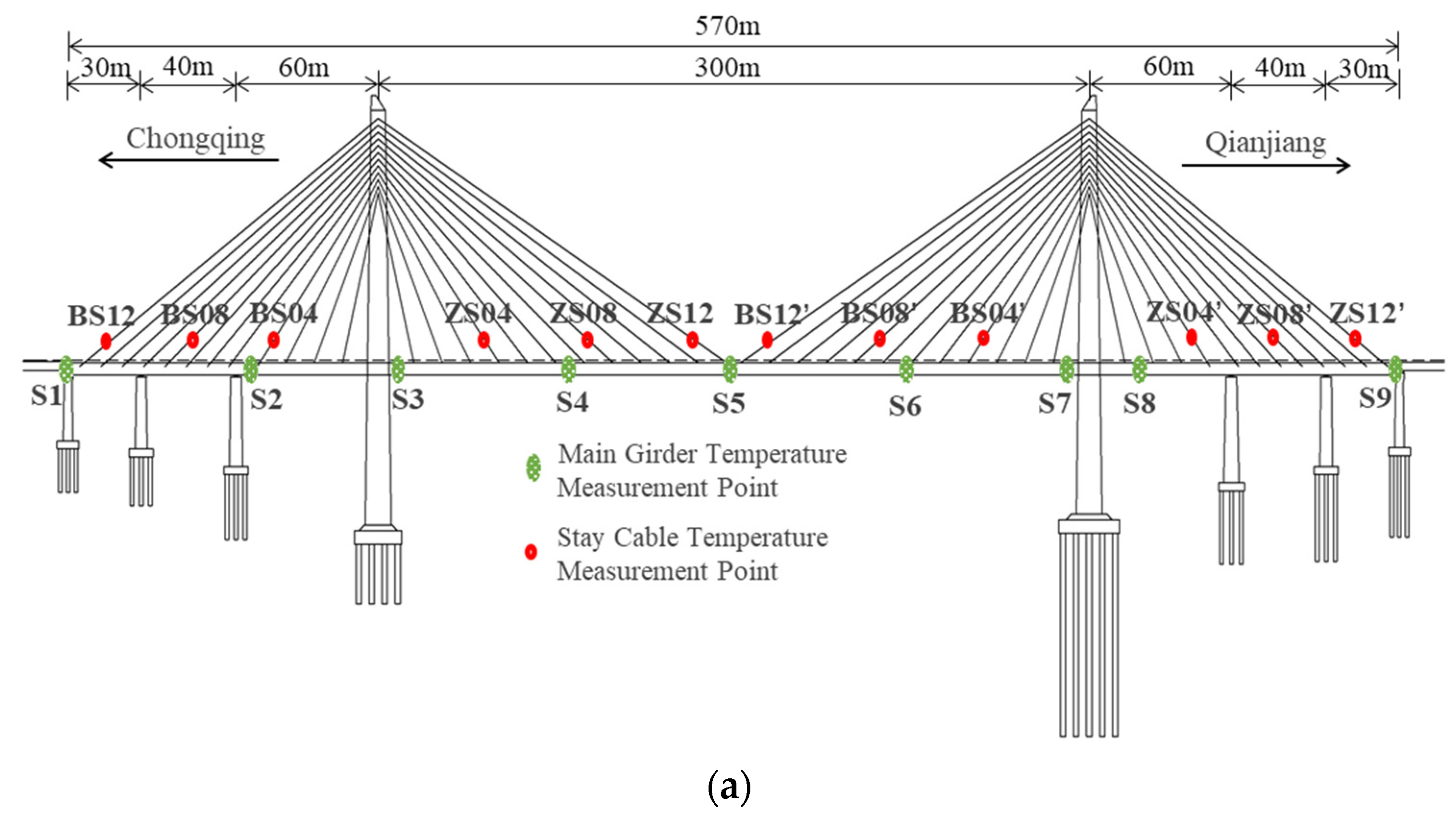
Figure 1. Layout of temperature sensors for the composite girder and cables. (a) Elevation view; (b) cross-section of the composite girder–ballastless track.
Buildings 16 01513 g001aBuildings 16 01513 g001b
Figure 2. Temperatures of the composite girder and cables from August 16 to August 18: (a) cable; (b) concrete deck of the composite girder.
Buildings 16 01513 g002
Figure 3. The integrated finite element model of bridge–ballastless track system.
Buildings 16 01513 g003
Figure 4. Longitudinal resistance model of the rail fastener.
Buildings 16 01513 g004
Figure 5. Cases 11 and 12 of temperature loads: (a) positive temperature gradients of concrete bridge deck; (b) negative temperature gradients of concrete bridge deck.
Buildings 16 01513 g005
Figure 6. Cases 13 and 14 of temperature loads (nonlinear temperature increase on one side of the bridge pylon).
Buildings 16 01513 g006
Figure 7. Deformation of the bridge–track system under Load Cases 1 and 2 (unit: mm): (a) uniform temperature increase (Case 1); (b) uniform temperature decrease (Case 2).
Buildings 16 01513 g007
Figure 8. Displacement of the composite girder under temperature Cases 3 to 14: (a) vertical displacement under various temperature-increase cases; (b) vertical displacement under various temperature-decrease cases; (c) longitudinal displacement under various cases.
Buildings 16 01513 g008aBuildings 16 01513 g008b
Figure 9. Maximum vertical displacement of the composite girder under temperature loads: (a) temperature variation in girder; (b) temperature variation in pylon; (c) temperature variation in cable.
Buildings 16 01513 g009
Figure 10. Effects of uniform temperature increase (Case 1): (a) rail’s displacement; (b) track slab’s displacement; (c) relative displacement.
Buildings 16 01513 g010
Figure 11. Effects of temperature increase in composite girder (Case 3): (a) rail’s displacement; (b) track slab’s displacement; (c) relative displacement.
Buildings 16 01513 g011
Figure 12. Effects of temperature increase in pylon (Case 7): (a) rail’s displacement; (b) track slab’s displacement; (c) relative displacement.
Buildings 16 01513 g012
Figure 13. Effects of temperature increase in cable (Case 9): (a) rail’s displacement; (b) track slab’s displacement; (c) relative displacement.
Buildings 16 01513 g013
Figure 14. Effects of temperature difference between concrete bridge deck and steel beam (Case 5): (a) rail’s displacement; (b) track slab’s displacement; (c) relative displacement.
Buildings 16 01513 g014
Figure 15. Linear fitting of atmospheric temperature and bridge structure temperature: (a) temperature of the girder; (b) temperature of the cable.
Buildings 16 01513 g015
Figure 16. Prediction of girder’s vertical displacement caused by temperature change in girder: (a) June 2024; (b) January 2025.
Buildings 16 01513 g016
Figure 17. Prediction of girder’s vertical displacement caused by temperature change in cable: (a) June 2024; (b) January 2025.
Buildings 16 01513 g017
Table 1. Material properties.
MaterialElastic Modulus
(MPa)
Linear Expansion Coefficient (°C−1)
Concrete (C40 grade)3.40 × 1041.0 × 10−5
Concrete (C50 grade)3.45 × 10⁴
Concrete (C55 grade)3.55 × 10⁴
Steel (Q345qD, Q345qE)2.06 × 1051.2 × 10−5
Cable1.95 × 105
Table 2. Temperature Load Cases 1–10.
CaseOverall StructureComposite GirderConcrete Bridge Deck of the Composite GirderSteel Box Beam of the Composite GirderPylonCable
Case 1+22.4 °C
Case 2−22.4 °C
Case 3 +5.7 °C
Case 4 −9.1 °C
Case 5 +7 °C+22.4 °C
Case 6 −13 °C−22.4 °C
Case 7 +15 °C
Case 8 −15 °C
Case 9 +10 °C
Case 10 −10 °C
Table 3. Comparison of FEM and theoretical vertical displacements.
CasesFEM (mm)Theoretical (mm)Relative Error
Case 38.531.172.6%
Case 4−13.6−51.873.7%
Case 9−58.1−80.3327.6%
Case 1058.178.2325.7%
Table 4. Summary of maximum temperature deformation of the bridge.
CasesMaximum Longitudinal Displacement DX (mm)Maximum Vertical Displacement DZ (mm)
PylonThe Beam End of the Side Span of the Composite GirderPylonThe Middle of the Central Span of the Composite Girder
Case 136.067.035.51.5
Case 2−36.0−66.9−35.5−1.5
Case 3−9.3−10.1−0.01678.5
Case 4−14.5−15.90.029−13.6
Case 53.535.611.2−71.6
Case 6−12.1−47.7−20.743.1
Case 715.20.98622.742.7
Case 8−15.2−0.986−22.7−42.7
Case 919.50.70.443−58.1
Case 10−19.5−0.7−0.44358.1
Case 11−5.8−6.8−0.126.5
Case 123.03.40.06−3.3
Case 13−1.9−0.0332.74.9
Case 141.90.033−2.7−4.9
Disclaimer/Publisher’s Note: The statements, opinions and data contained in all publications are solely those of the individual author(s) and contributor(s) and not of MDPI and/or the editor(s). MDPI and/or the editor(s) disclaim responsibility for any injury to people or property resulting from any ideas, methods, instructions or products referred to in the content.