Article

Predicting Degradation of Axial Compression Performance in Permanent–Temporary Integrated RC Columns of the Pinglu Canal Under Sustained Loading and Chloride Salt

1
Guangxi Pinglu Canal Construction Co., Ltd., Nanning 530000, China
2
Guangxi Pinglu Canal Digital Intellligence Technology Co., Ltd., Nanning 530000, China
3
Guangxi Road Construction Engineering Group Co., Ltd., Nanning 530004, China
4
China Construction Eighth Engineering Bureau Co., Ltd., Shanghai 200012, China
5
College of Civil Engineering and Architecture, Guangxi University, Nanning 530004, China
*
Author to whom correspondence should be addressed.
Buildings 2026, 16(7), 1407; https://doi.org/10.3390/buildings16071407
Submission received: 19 January 2026 / Revised: 22 March 2026 / Accepted: 26 March 2026 / Published: 2 April 2026

Abstract

Reinforced concrete (RC) structures in marine environments face severe durability challenges due to chloride-induced corrosion. This study investigates the corrosion mechanism and degradation of axial compressive performance in RC columns under the combined effects of sustained loading and corrosion, taking the permanent–temporary integrated RC columns of the Pinglu Canal project as an example. The experimental variables included different sustained load levels and degrees of corrosion. Twelve rectangular RC columns were designed and tested. A specialized setup was developed to simultaneously apply sustained load and induce corrosion to the columns, while monitoring their creep deformation. The columns were subjected to accelerated electrochemical corrosion in a 5% NaCl solution, concurrently under sustained loads of 0, 0.3, and 0.6 times their designed axial compressive capacity, with exposure durations of 0, 30, 60, and 120 days, respectively. The study examined the effects of sustained load level and corrosion degree on the failure mode, concrete creep deformation, and load–displacement curves of the corroded RC columns. The results indicated that sustained loading shortened the duration of concrete expansion deformation and reduced its peak value. Furthermore, the expansion deformation of concrete delayed the creep of corroded columns by 25 to 35 days; after the expansion recovery, the creep rate increased significantly. For corroded columns without sustained loading, the ultimate bearing capacity decreased by 32.0% to 47.8%, with degradations in both stiffness and ductility. The application of sustained loading alleviated the degradation in the ultimate bearing capacity and stiffness of the corroded columns but exacerbated the degradation of their ductility. Finally, considering the effects of concrete expansion deformation and steel corrosion, a predictive model for the creep of RC columns under the coupled action of sustained loading and corrosion was proposed, aiming to provide a theoretical basis for the durability design and maintenance of RC structures in the Pinglu Canal project.

1. Introduction

Reinforced concrete (RC) structures are widely used in various infrastructure projects due to their low cost, relatively high strength, and easy availability of raw materials. However, in marine and offshore environments, these structures are continuously exposed to the ingress of harmful substances like chloride ions, which severely threatens their safety and durability [1]. Chloride ion penetration and concrete carbonation can induce reinforcement corrosion, which is the primary cause of performance degradation for marine concrete structures during their service life [2,3,4]. This challenge is particularly critical for the “Permanent-Temporary Integrated” structures of the Pinglu Canal [5]. These structures are required to serve temporarily during the construction phase and permanently during the operational phase. Throughout their entire life cycle, they may endure more complex coupled effects of structural loads and environmental actions, leading to more intricate performance degradation mechanisms [6]. Therefore, research on the durability of such engineering structures under harsh environmental conditions holds significant theoretical value and considerable practical engineering importance [7].
Steel corrosion consumes the original steel material and produces less dense corrosion products. This results in a reduced cross-sectional area of the reinforcement, increased stress, and decreased yield strength [8,9]. Non-uniform corrosion leads to significant variations in the residual cross-section along the length of the bar, markedly reducing its ductility [10,11,12]. As the volume of corrosion products is approximately twice that of the consumed steel, their expansion generates circumferential tensile stresses in the surrounding concrete. Once these stresses exceed the concrete’s tensile strength, cracking occurs [12,13]. These cracks provide pathways for further chloride ingress, accelerating the corrosion rate and eventually leading to the spalling of the concrete cover when cracks interconnect [14,15,16,17]. In addition, cracking significantly reduces the bond capacity between steel and concrete [17,18,19]. Corrosion of reinforcement not only reduces the structural safety and durability of RC structures but also shortens their service life [1]. Therefore, it is essential to study the effect of steel corrosion on the mechanical behavior of marine concrete structures. Refs. [20,21] showed that corrosion reduces the axial compressive strength and ultimate strain of the concrete cover in columns. Ref. [22] found that both the stiffness and ultimate strength of RC columns decrease as corrosion increases, with the reduction rate of ultimate load capacity being influenced by load eccentricity and stirrup spacing. Ref. [23] demonstrated that circular columns exhibit higher axial cyclic load capacity compared to square columns, and that this capacity decreases progressively with increasing corrosion and confinement. Ref. [24] investigated the seismic performance of corroded RC beams and observed that the failure mode shifted from flexural-shear failure to flexural-tension failure as the degree of tensile reinforcement corrosion increased. Ahmet experimentally studied HDPE-confined self-compacting concrete columns under sulfate-acid attack and found that HDPE confinement effectively mitigated strength degradation (peak load drop of only 0.3–1% vs. 45–50% in unconfined specimens) and increased fracture energy by up to 55 times [25]. Furthermore, based on experimental and theoretical studies, numerous researchers have developed machine learning–based models to predict the residual load-bearing capacity of corroded reinforced concrete members [26,27].
However, in all the studies mentioned above, the corrosion of RC members occurred without the application of any external load. In reality, RC components in service are often subjected to corrosion while under load [28]. Some researchers have investigated the combined effects of sustained loading and corrosion on the mechanical performance of RC beams. The results indicate that load-induced internal microcracking and transverse cracking in concrete accelerate the corrosion of reinforcement and facilitate crack propagation. Larger crack widths can reduce the time to corrosion initiation [29,30]. Compared to the effects of loading or corrosion alone, the combined action of sustained load and corrosion leads to a more rapid decline in the ultimate strength and maximum deflection of beams. The effect of corrosion on beam deflection is significant, and the failure mode may shift from ductile to brittle [31,32]. As both the load level and the degree of corrosion increase, the flexural stiffness of beams initially increases and then decreases. Ductility reduces more rapidly than load-carrying capacity, and the influence of corrosion on the ductility of RC beams depends on the initial ductility of the reinforcement [33,34].
The Pinglu Canal Youth Hub, a critical node connecting the river to the sea, features reinforced concrete structures persistently exposed to chloride-ion erosion from seawater intrusion and frequent water-level fluctuations, posing significant durability challenges. Under such practical engineering conditions, the combined effect of mechanical load and chloride-ion corrosion on reinforced concrete (RC) columns often leads to more severe performance degradation than the action of either factor alone, making the study of their synergistic effect highly relevant. Refs. [24,35] indicates that sustained loading not only influences the mass loss of reinforcement but also constrains the ultimate strength of columns. Concurrently, under combined freeze–thaw cycles and seawater immersion, crack propagation accelerates chloride ion migration. Although existing studies have partially revealed the patterns of this load-corrosion coupling effect [36], current experimental methods face limitations: loading devices are susceptible to corrosion by aggressive media like NaCl solutions, compromising reusability; the loss of sustained load during tests is often overlooked; short-term accelerated corrosion tests struggle to accurately reflect natural corrosion processes; furthermore, the creep behavior of concrete under combined sustained load and corrosion requires deeper investigation [37]. To more accurately simulate the service conditions of RC structures in real-world projects like the Pinglu Canal, more systematic research is essential. This study, based on the Pinglu Canal’s environmental context, designs a sustained load-corrosion testing apparatus capable of real-time load monitoring and adjustment. It focuses on investigating the creep behavior of RC columns under the combined action of sustained load and corrosion, aiming to provide references for enhancing the durability design of key hydraulic structures such as the Youth Hub [38,39].

2. Experimental Program

2.1. Sample Design and Preparation

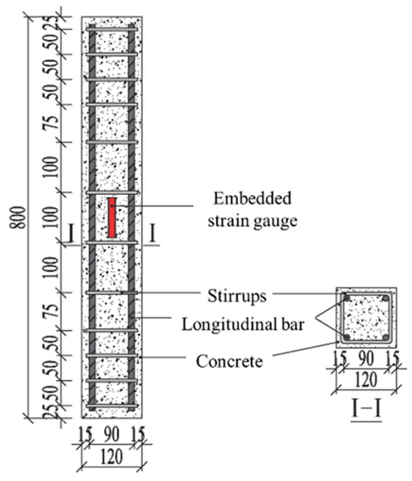
This experiment was based on the reinforced concrete columns of the permanent–temporary integrated structure in the Pinglu Canal Project. Using a scale-reduced method, 12 reinforced concrete column specimens were designed and manufactured to study the mechanical properties under the combined action of sustained loading and chloride-induced corrosion. Among the 12 specimens, 9 were used to simulate the coupled effect of sustained load and chloride ion corrosion under actual engineering conditions. Two specimens were subjected only to sustained load to serve as a control group for the single factor of loading, and one specimen served as a baseline, free from both load and corrosion, for calibrating the initial mechanical properties of the components. All scale-reduced specimens had a height (H) of 800 mm and a rectangular cross-section with a uniform width (B) of 120 mm. The reinforcement layout was consistent with the prototype: each reinforcement cage consisted of 4 longitudinal bars and 12 stirrups. The main longitudinal reinforcement used deformed steel bars with a diameter of 12 mm, while the stirrups were made of plain round steel bars with a diameter of 6 mm. The concrete cover thickness was controlled at 15 mm to match the design standards of the actual project. Refer to Figure 1 for specific structural details.
The main test variables were the sustained load level (0, 0.3, 0.6) and the degree of steel corrosion (0%, 5%, 10%, 20%). The specimens were labeled according to the format A-Y-Z, where Y indicates the sustained load level (coded as 0, 1, and 2 for n = 0, 0.3, and 0.6, respectively), and Z represents the designed corrosion degree ηd of the reinforcement. The detailed parameters of the RC column specimens are summarized in Table 1.
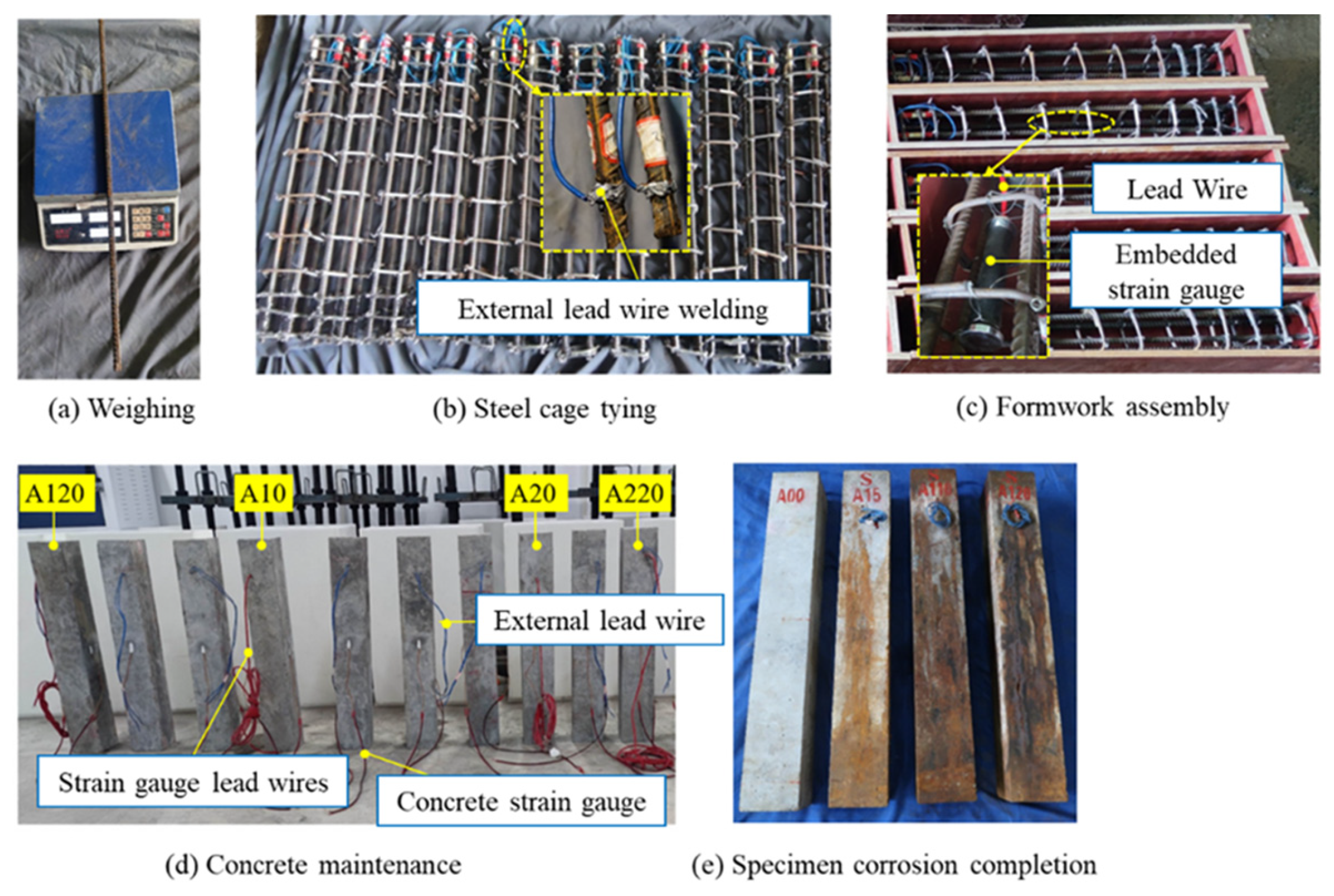
The specimen fabrication process is shown in Figure 2. Including the following steps: (1) Before binding the reinforcement, the initial weight of each longitudinal bar and stirrup was measured for later calculation of the actual corrosion degree after testing; (2) Prior to concrete casting, external leads were welded to one end of the longitudinal bars to enable accelerated corrosion through impressed current; (3) To prevent corrosion at the ends of the specimen, epoxy-coated reinforcement was used within a 100 mm range from both ends; (4) To investigate the effect of combined sustained load and corrosion on concrete creep, embedded strain gauges were installed at the mid-height of the specimen to monitor concrete strain; (5) After 28 days of curing, surface strain gauges were attached to two adjacent sides of the specimen to monitor the direction of sustained load; (6) Using a self-designed sustained load-corrosion device, combined sustained load and corrosion were applied to the RC columns to simulate coupled damage. The procedure for applying sustained load and corrosion was as follows: (1) A sustained load Ns was applied to the RC column through the loading mechanism, where the load level n was set at 0, 0.3, or 0.6. The design bearing capacity Nd of the column was calculated according to relevant codes, and Ns = n × Nd; (2) After 4 days of sustained loading, a 5% NaCl solution was poured into the plastic tank; (3) After 3 days of immersion, when the concrete cover was fully saturated, an electrical circuit was established by connecting the anode to the RC column, the NaCl solution, a stainless steel conductive bar, and the cathode. A constant current was then applied using a DC power supply to initiate accelerated corrosion.

2.2. Properties of the Materials

The concrete had a strength grade of C50, with the mix proportions detailed in Table 2. The measured slump was 145 mm, and the water-cement ratio was 0.35. On the day of casting, three plain concrete cubes were prepared and cured under the same conditions as the specimens. The average 28-day compressive strength fcu of the concrete cubes was 53.3 MPa, and the average elastic modulus Ec was 35.5 GPa, as summarized in Table 3. HRB400 steel bars were used as longitudinal reinforcement, with an average yield strength fy of 457.8 MPa. For stirrups, HPB300 steel bars were employed, exhibiting an average fy of 314.6 MPa.
In this section, where applicable, authors are required to disclose details of how generative artificial intelligence (GenAI) has been used in this paper (e.g., to generate text, data, or graphics, or to assist in study design, data collection, analysis, or interpretation). The use of GenAI for superficial text editing (e.g., grammar, spelling, punctuation, and formatting) does not need to be declared.

2.3. Sustained Load and Corrosion Setup

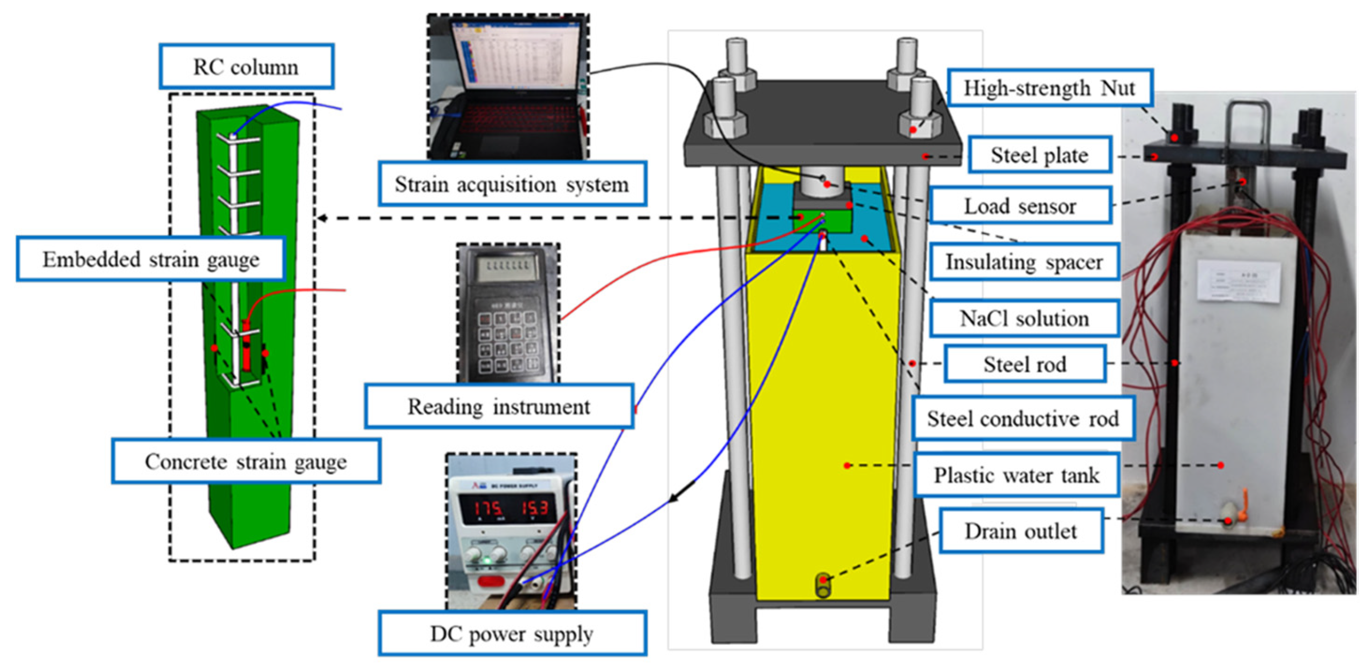
To investigate the corrosion mechanisms, creep deformation, and axial compression behavior of RC columns under the combined action of sustained load and corrosion, a specialized sustained load-corrosion apparatus was designed in this study. The setup consists of three main components: a loading system, a corrosion system, and a measurement system, as illustrated in Figure 3. Axial load is applied to the RC column by tightening nuts at both ends of the high-strength steel tie rods. The corrosion system includes a tank containing a 5% sodium chloride (NaCl) solution, a stainless steel conductive bar, and a DC power supply. To prevent corrosion of the loading assembly, the NaCl solution is isolated within a plastic tank. The RC column and the stainless steel bar are fully immersed in the electrolyte. The anode of the DC power supply is connected to the main reinforcement of the column, while the cathode is connected to the stainless steel bar, forming a closed electrical circuit: anode → RC column → NaCl solution → stainless steel bar → cathode. Accelerated corrosion is achieved by maintaining a constant current through this path.
The measurement system consists of a load cell, surface-mounted strain gauges on the concrete, and embedded strain gauges within the concrete column. The load cell, with an accuracy of 0.05%, is used to monitor variations in the axial load. Two longitudinal strain gauges attached to the surface of the RC column are employed to monitor the load direction during the application of the sustained load; these gauges were deactivated once the target load was reached and maintained. Throughout the accelerated corrosion process, loss of sustained load may occur due to concrete shrinkage and creep. Whenever the load loss exceeds 5% of the designed sustained load value, the nuts are retightened to restore and maintain the prescribed load level. To monitor concrete strain, embedded vibrating wire strain gauges were installed in the RC column. Data from these sensors were collected daily using a portable readout unit.

2.4. Test Setup and Instrumentation

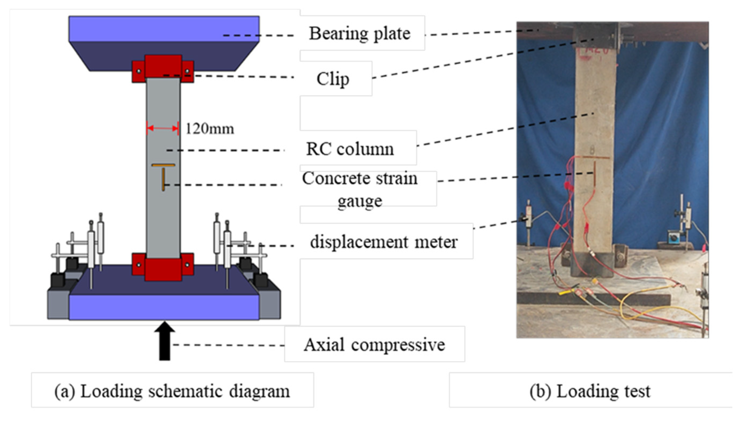
After being subjected to the combined effects of sustained load and corrosion, the specimens were removed from the testing apparatus and tested under axial compression until failure. The setup and instrumentation for the axial compression test are shown in Figure 4. A 10,000 kN hydraulic jack was used to apply axial compression under displacement control at a constant rate of 0.2 mm/min. The test was terminated when the load dropped to 70% of the peak load or upon sudden failure. To prevent premature local damage, both ends of the specimen were protected with specially designed end fixtures. One longitudinal and one transverse strain gauge were attached at the mid-height (H/2) on two adjacent faces of each specimen. Before formal loading, a preloading procedure was carried out to ensure full contact between the specimen and the loading equipment.

3. Test Results and Discussion

3.1. Failure Modes of Specimens

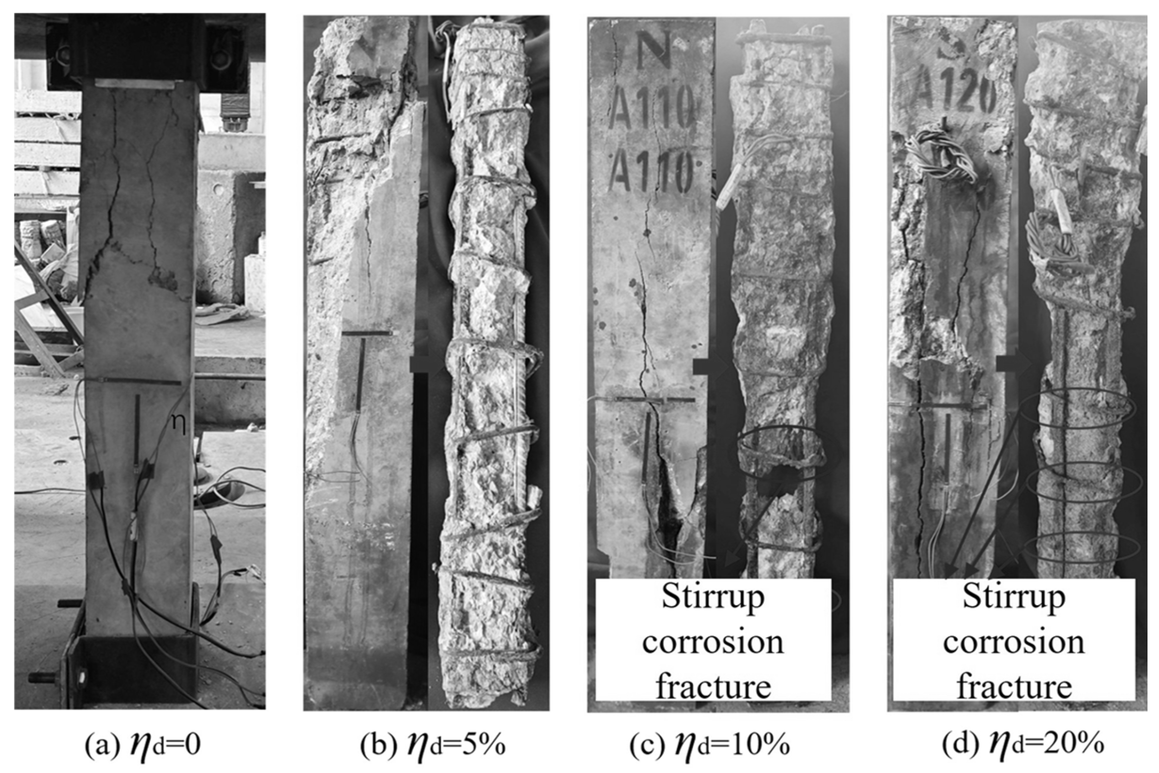
Sustained load was observed to have no significant influence on the failure mode of the corroded columns. The typical failure patterns of the specimens varied with the designed corrosion degree, as shown in Figure 5.
For uncorroded RC columns, failure occurred by splitting at the ends. When the designed corrosion degree was low (0% to 5%), the failure mode showed no notable change. As the designed corrosion degree increased to 10% and 20%, the number and width of corrosion-induced cracks increased significantly, leading to a marked proliferation of cracks on the surface of the RC columns at failure. This is attributed to the propagation of corrosion cracks under compressive loading. Since epoxy-coated reinforcement was used within 100 mm of both ends of the columns, corrosion damage in these regions was minimal, while other parts experienced more severe corrosion. Consequently, at higher designed corrosion degrees (10% to 20%), the failure mode shifted from end splitting to a drum-type failure characterized by the expansion of corrosion-induced cracks along the height of the column.

3.2. Concrete Deformation Response

Previous studies have indicated that the presence of initial pores and microcracks in concrete reduces under sustained compressive stress, leading to a decrease in the diffusion coefficient of chloride ions [32]. This finding explains why, in chloride-rich environments, RC columns under sustained loading exhibit a lower degree of steel corrosion compared to those without sustained load. This study further elucidates the process by examining the deformation response of concrete in RC columns subjected to the combined action of sustained load and corrosion.
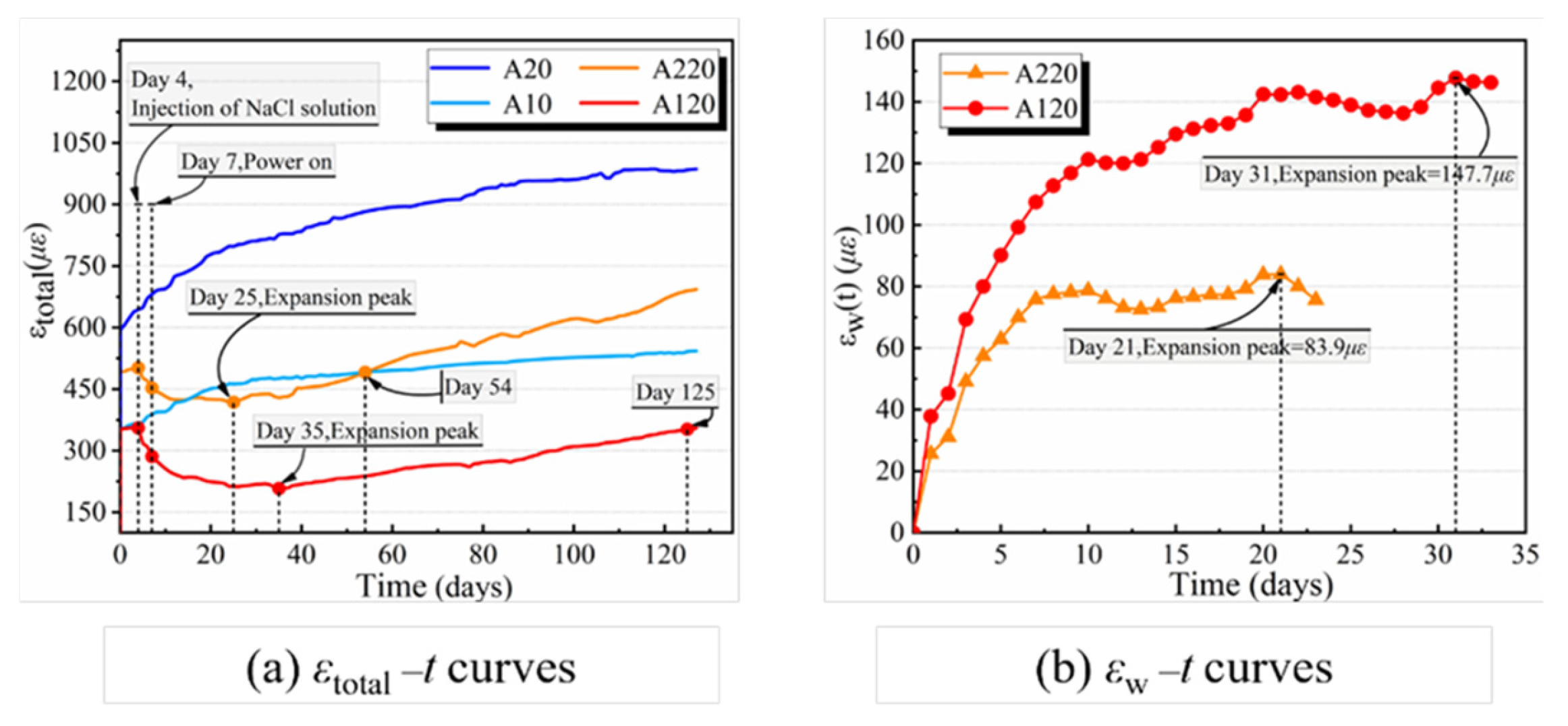
The total longitudinal strain εtotal in the concrete of specimens A20, A10, A220, and A120 was measured using embedded strain gauges. The parameters of the strain gauges used in this study are provided in Table 4. The variation in total longitudinal strain εtotal and swelling deformation εw over time t is illustrated in Figure 6.
As shown in Figure 6a, for specimens A20 and A10 subjected to sustained load only, the deformation after 30 days of loading accounted for approximately 80% of the deformation after 120 days. Beyond 120 days, the deformation development tended to stabilize, which is attributed to the gradually decreasing rate of concrete deformation over time. In contrast, the deformation behavior of specimens A220 and A120 under combined sustained load and corrosion differed significantly. During the first 4 days under sustained load alone, the concrete strain increased with time. On the 4th day, the NaCl solution was poured into the tank, and immediately after immersion, the concrete strain began to decrease. Accelerated corrosion began on the 7th day after power was supplied. For specimen A220, the concrete strain decreased to its lowest point at 21 days after immersion, then started to increase again. It returned to the instantaneous strain value at loading by 50 days after immersion. After 120 days of immersion, its total deformation was significantly smaller than that of specimen A20. Similarly, specimen A120 reached its minimum strain at 31 days after immersion, began increasing afterward, and recovered to the initial loading strain by 118 days after immersion. Its final deformation after 120 days was also smaller than that of specimen A10. The underlying mechanism of this phenomenon can be divided into two stages: (1) Early chemical expansion stage (t < 30 days): During this stage, chloride ions have not yet reached the steel reinforcement surface. However, chlorides that have penetrated into the concrete pores react with cement hydration products to form chloroaluminate crystals such as Friedel’s salt [40]. This crystallization process induces slight volumetric expansion, which fills capillary pores and generates internal compressive stresses. As a result, the concrete matrix temporarily becomes denser and stiffer, thereby suppressing creep deformation-manifested as a reduced early creep rate or even a noticeable “delayed recovery” behavior. (2) Later-stage corrosion-induced cracking stage (t > 30 days): Once the chloride ion concentration at the steel surface exceeds the critical threshold, active corrosion initiates. The resulting corrosion products (Fe(OH)2) can occupy 2–6 times the original volume of the steel, generating significant radial expansive pressure. This leads to the formation of longitudinal cracks along the reinforcing bars [41]. These cracks reduce the effective cross-sectional area, release restraining stresses, and degrade the composite stiffness of the member, consequently causing a marked acceleration in the creep rate under sustained loading.
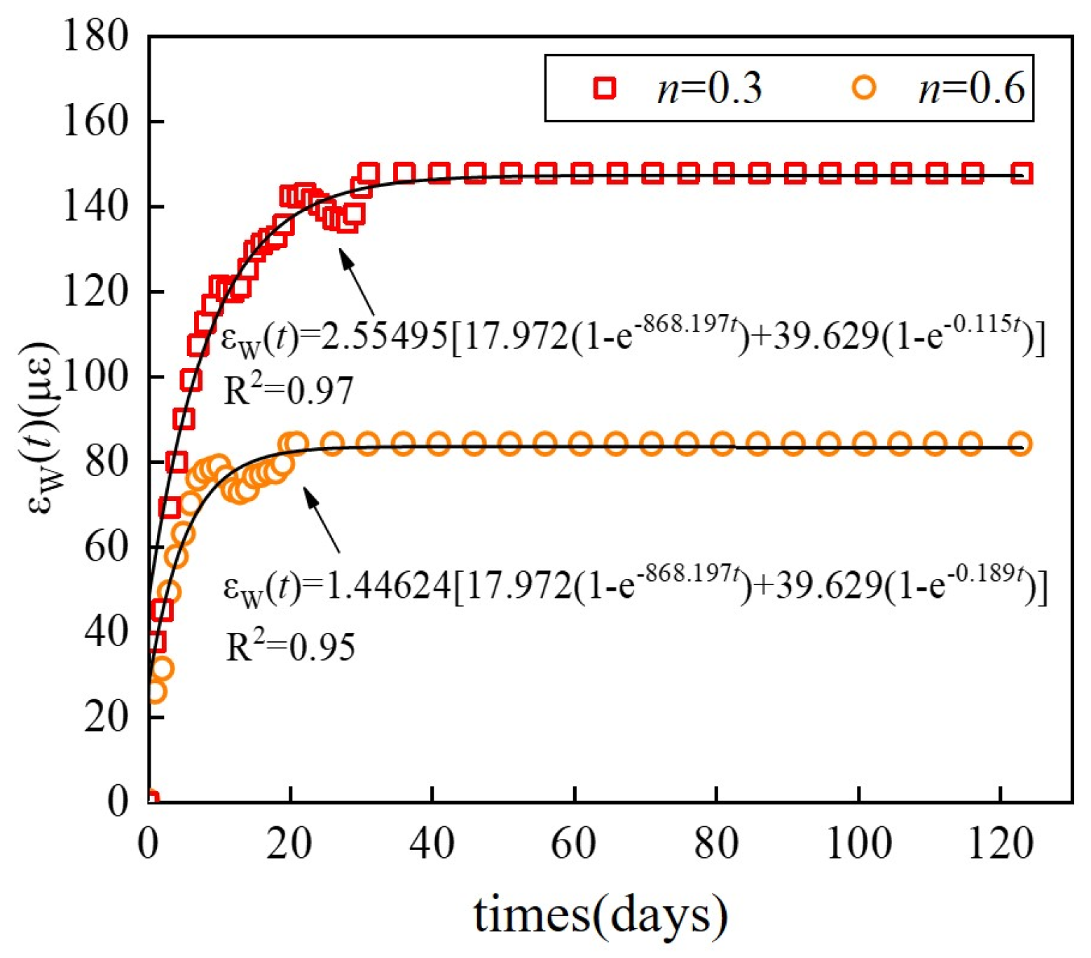
From Figure 6b, it can be observed that the swelling deformation developed rapidly within the first 10 days after immersion, then slowed down. Specimen A220 reached its peak swelling deformation of 83.9 με on the 21 day after immersion, while specimen A120 reached a peak of 147.7 με on the 31 day. In contrast, unconstrained concrete typically reaches a peak swelling deformation of about 130 με around 45 days after water immersion. This indicates that sustained loading shortens the time to reach peak swelling deformation and reduces its magnitude, with a more pronounced effect under higher load levels. This phenomenon is likely due to the fact that sustained loading alters the internal pore structure of concrete, inhibiting fluid penetration [39]. Consequently, compared to unconstrained concrete, sustained load reduces the diffusion coefficient of chloride ions by limiting solution penetration, thereby decreasing the chloride concentration in concrete and ultimately reducing the corrosion rate of reinforcement [42].

3.3. Load-Longitudinal Displacement Curves

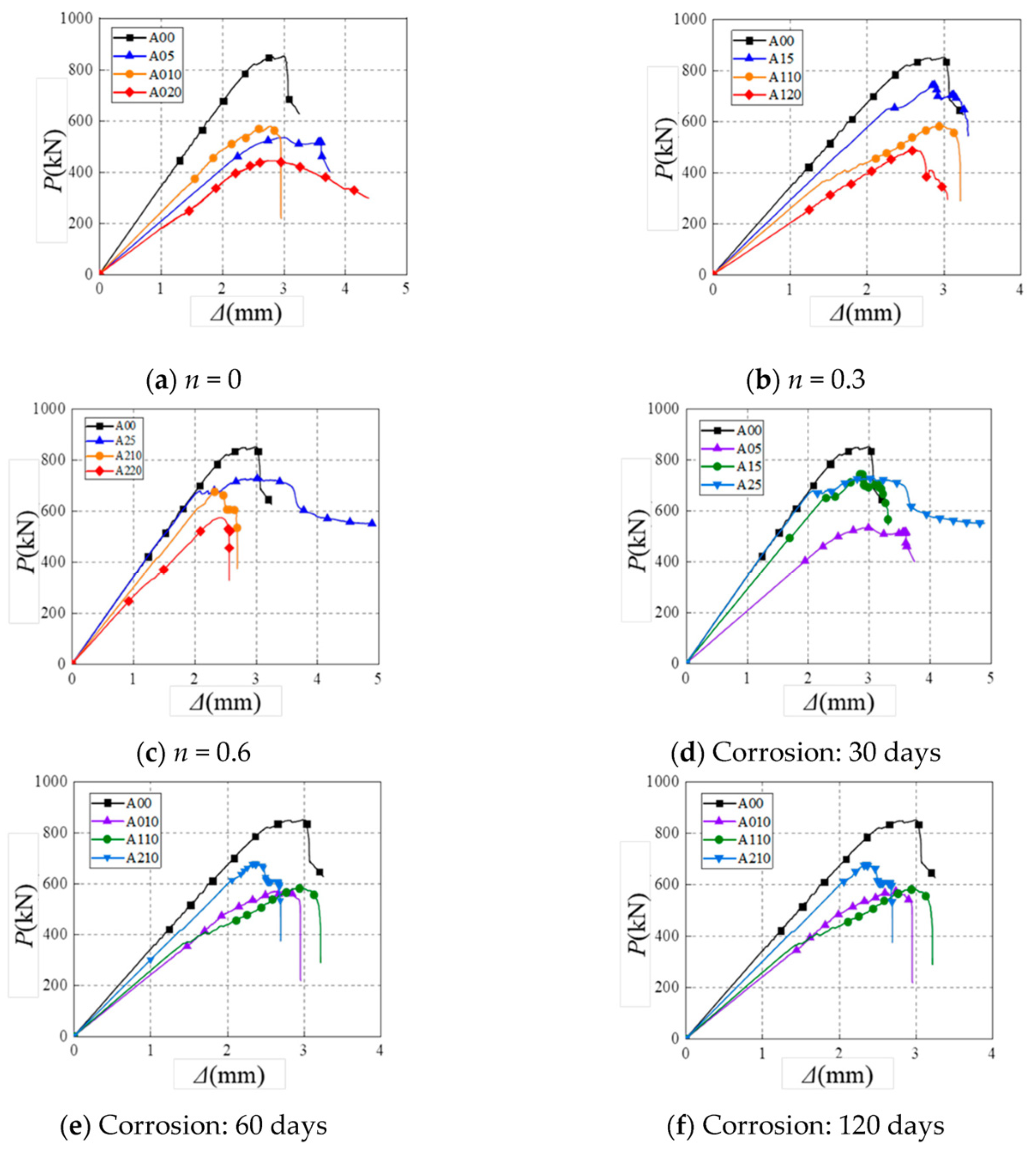
Figure 7 presents the load–displacement curves of the ten tested specimens. Compared to the undamaged reference column A00, the overall shape of the curves for the columns subjected to combined sustained load and corrosion showed no significant change. All curves can be divided into three typical phases: the elastic stage, the elastoplastic stage, and the descending branch. As shown in Figure 7a–c, under the same sustained load level, the slope of the elastic segment of the load–displacement curve gradually decreased as the designed corrosion degree increased. This indicates that steel corrosion reduces the elastic stiffness of the RC columns, a phenomenon also reported in previous studies. The reduction in stiffness is attributed to the loss of steel cross-sectional area due to corrosion and the cracking of the concrete section, both of which weaken the effective load-bearing cross-section. Furthermore, the vertical displacement at failure decreased with increasing designed corrosion degree, demonstrating that corrosion also reduces the ductility of the RC columns.
As shown in Figure 7d–f, under the same designed corrosion degree, the slope of the elastic segment in the load–displacement curves increases with higher sustained load levels. This indicates that, compared to the effect of corrosion alone, the application of sustained loading mitigates the degradation of stiffness in corroded columns. This can be attributed to the fact that sustained loading reduces the actual degree of steel corrosion in the specimens. On the other hand, the vertical displacement at failure decreases as the sustained load level increases, demonstrating that sustained loading reduces the ductility of the RC columns. A similar phenomenon was observed in ref. [33] during the study of RC columns under high sustained load levels.

4. Prediction of Creep in RC Columns Under Sustained Load and Corrosion

To facilitate an analysis of the effect of combined sustained load and corrosion on concrete creep, the traditional creep prediction model was employed to calculate the creep coefficient of the specimens. The calculated results were then compared with the experimental data. The ACI 209 creep prediction model [43] is given as follows:
φ ( t , τ 0 ) A C I 209 R = t 0.6 10 + t 0.6 × K 1 K 2 K 3 K 4 K 5 K 6
In the formula, K1 represents the influence coefficient of loading age; K2 denotes the influence coefficient of ambient relative humidity—with a value of 99% assigned due to the specimens being immersed in NaCl solution; K3 indicates the influence coefficient of the specimen’s average thickness, taken as 120 mm; K4 stands for the influence coefficient of slump, which was 145 mm; K5 refers to the influence coefficient of fine aggregate, with fine aggregate accounting for 32% by mass; and K6 is the influence coefficient of air content, taken as 6%.
Based on the experimental observations and results, the following assumptions are proposed:
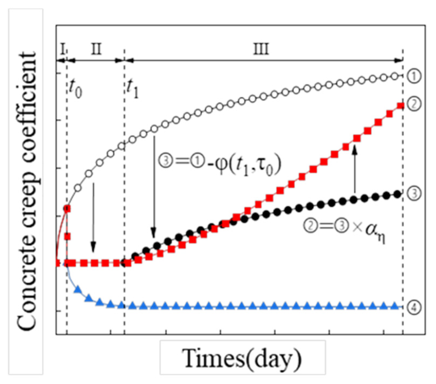
(1) After immersion in NaCl solution, the RC column undergoes swelling deformation, which offsets the creep that occurred prior to immersion, reducing it to zero. Once the swelling deformation stabilizes at its peak value, concrete creep resumes its growth.
(2) The post-recovery growth trend of creep is similar to that of an RC column under sustained load alone at the same time point, but is influenced by the degree of steel corrosion.
Building upon the ACI 209 model, a creep prediction model for RC columns under combined sustained load and corrosion is developed, incorporating the effects of concrete swelling deformation and steel corrosion. The calculation procedure is illustrated in Figure 8. The swelling deformation of concrete is modeled based on the hydraulic concrete swelling deformation model proposed in [13] for different water-to-binder ratios, with modifications accounting for the sustained load level and the presence of NaCl solution. The water-to-binder ratio of the concrete in this study is 0.35.
ε W ( t t 0 ) = a 17.984 ( 1 e 868.197 × ( t t 0 ) ) + 39.629 ( 1 e 0.180 b × ( t t 0 )
In the formula, t0 denotes the time at which the RC column is immersed in the NaCl solution, and a and b are undetermined parameters obtained through regression analysis of experimental data, as illustrated in Figure 9. During the swelling deformation phase (Stage II), the creep coefficient of concrete is calculated using the following equation, which yields Curve ④ shown in Figure 8:
φ ( t , τ 0 ) = ε W ( t t 0 ) ε 0
Due to the effects of steel corrosion, the bond strength between concrete and reinforcement decreases, leading to a reduction in the restraining effect of reinforcement on concrete creep. As a result, the rate of increase in the concrete creep coefficient accelerates. The existing studies have investigated the relationship between the degree of steel corrosion and the bond strength of concrete, proposing a reduction coefficient β(η) for the bond strength between corroded steel and concrete [44,45,46]:
β ( η ) = 1 + 0.5625 η 0.3375 η 2 + 0.55625 η 3 0.003 η 4 , ( η 7 % ) 2.0786 η 1.0369 , ( η 7 % )
A corrosion adjustment factor αη is introduced to modify the growth rate of the creep coefficient in Curve ③. The smaller the bond strength reduction coefficient β(η), the weaker the additional internal forces between the steel and concrete, and the faster the concrete creep increases. Therefore, it is assumed that the corrosion adjustment factor αη is inversely proportional to the bond strength reduction coefficient β(η):
φ ( t ) = α η ( φ ( t ) A C I 209 R φ ( t 1 ) A C I 209 R )
By superimposing Curve ② and Curve ④ from Figure 8, the creep prediction model for RC columns under the combined action of sustained load and corrosion in a fully NaCl-immersed environment is obtained as follows:
φ ( t , τ 0 ) = φ ( t , τ 0 ) A C I 209 R , t t 0 ε W ( t t 0 ) ε 0 , t 0 t t 1 ε W ( t t 0 ) ε 0 + φ ( t , τ 0 ) A C I 209 R φ ( t 1 , τ 0 ) A C I 209 R k × β ( η ) , t t 1
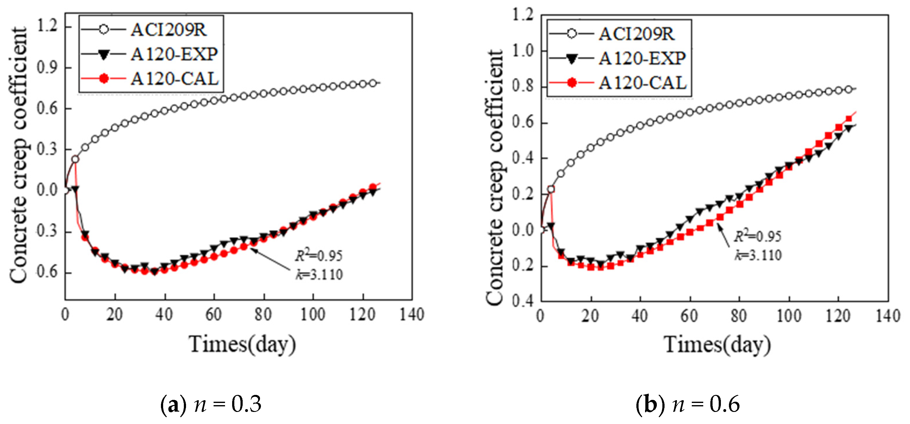
Substitute t0 into Equations (2) and (3) to calculate the creep coefficient during the swelling deformation phase (Stage II). Studies have shown that both longitudinal and stirrup reinforcement restrain concrete creep. Therefore, the average corrosion degree of the reinforcement is substituted into Equation (4) to compute the bond strength reduction coefficient β(η), under the assumption that the corrosion rate remains constant over the same period. The result is then substituted into Equation (6) to obtain the predicted creep coefficient, where k is a calibrated parameter that depends on the axial load level n, reflecting the accelerated creep development under higher compression.
The coefficient of determination (R2) is commonly used to evaluate the agreement between predicted and measured values [47,48], and is calculated as follows:
R 2 = 1 i ( y i f i ) 2 i ( y i y ) 2
The solution results are presented in Figure 10. For the RC column with n = 0.3, the coefficient of determination R2 reaches a maximum value of 0.94 when k = 3.756. For the column with n = 0.6, R2 attains a maximum of 0.95 when k = 3.110. These results confirm the validity of the proposed prediction method.

5. Conclusions and Discussion

5.1. Conclusions

This study presents an experimental investigation on the corrosion mechanisms, creep deformation, and axial compressive behavior of RC columns under the combined effects of sustained loading and corrosion. The main findings are as follows:
(1) The application of sustained load inhibits the penetration of NaCl solution into the concrete, thereby reducing the degree of steel corrosion. This mitigating effect is particularly noticeable in the early stage of corrosion. However, during the middle and late stages, as concrete creep resumes and longitudinal corrosion cracks develop, this reduction effect diminishes significantly.
(2) Under the effect of corrosion alone, the ultimate load, stiffness, and ductility of the RC columns all deteriorated. Compared to corrosion acting alone, the combined action of sustained load and corrosion slowed the degradation of the ultimate load and stiffness but accelerated the degradation of ductility.
(3) The swelling deformation of concrete delayed the development of creep in the RC columns, resulting in significant discrepancies between the observed creep behavior and predictions from the ACI 209R model. A new creep prediction model was proposed, incorporating the effects of concrete swelling deformation and steel corrosion. The predicted values show good agreement with the experimental measurements.

5.2. Discussion

Limitations regarding corrosion simulation: It should be noted that the impressed-current technique generates a more uniform corrosion distribution along the rebar length, whereas natural corrosion in marine environments is typically localized due to heterogeneous chloride penetration and oxygen availability. This idealization may lead to differences in crack localization and bond degradation compared to field conditions. Nevertheless, the accelerated method allows for a systematic investigation of the coupling effects between mechanical loading and corrosion-induced deterioration under controlled laboratory conditions. The trends observed—particularly the interaction between load level and creep development—provide valuable mechanistic insights, though quantitative extrapolation to real structures requires caution and further validation with non-uniform corrosion data.

Author Contributions

Conceptualization, X.W. and Z.Z. (Zhiwei Zhang); Methodology, X.W. and Z.Z. (Zhiwei Zhang); Software, X.W. and Z.Z. (Zhiwei Zhang); Validation, X.W. and Y.Z.; Formal analysis, Y.Z.; Resources, Z.Z. (Zhitai Zhang); Data curation, H.W. and Z.Z. (Zhitai Zhang); Writing—original draft, H.W. and Z.Z. (Zhitai Zhang); Writing—review and editing, L.H. and Y.Z.; Visualization, H.W., L.H. and J.Z.; Supervision, J.Z.; Project administration, L.H. and J.Z.; Funding acquisition, J.Z. All authors have read and agreed to the published version of the manuscript.

Funding

This research received no external funding.

Data Availability Statement

The original contributions presented in this study are included in the article. Further inquiries can be directed to the corresponding author.

Conflicts of Interest

Authors Xianzhang Wang, Zhitai Zhang, and Jianan Zheng were employed by the company Guangxi Pinglu Canal Construction Co., Ltd. Authors Xianzhang Wang, Zhitai Zhang, Yiming Zhou and Jianan Zheng were employed by the company Guangxi Pinglu Canal Digital Intellligence Technology Co., Ltd. Author Hancheng Wen was employed by the company Guangxi Road Construction Engineering Group Co., Ltd. Author Zhiwei Zhang was employed by the company China Construction Eighth Engineering Bureau Co., Ltd. The remaining author declares that the research was conducted in the absence of any commercial or financial relationships that could be construed as a potential conflict of interest.

References

  1. Chen, H.; Jiang, Y. Structural performance deterioration of corroding reinforced concrete columns in marine environments. Ocean Eng. 2022, 262, 13. [Google Scholar] [CrossRef]
  2. Balestra, C.; Nakano, A. Reinforcement corrosion risk of marine concrete structures evaluated through electrical resistivity: Proposal of parameters based on field structures. Ocean Eng. 2019, 187, 106167. [Google Scholar] [CrossRef]
  3. Fan, Z.; Xu, X. Fatigue reliability analysis for suspenders of a long-span suspension bridge considering random traffic load and corrosion. Structures 2023, 56, 104981. [Google Scholar] [CrossRef]
  4. Gülşan, M.E.; Alzeebaree, R.; Rasheed, A.A.; Niş, A.; Kurtoğlu, A.E. Development of fly ash/slag based self-compacting geopolymer concrete using nano-silica and steel fiber. Constr. Build. Mater. 2019, 211, 217–283. [Google Scholar] [CrossRef]
  5. Yang, X.; Liu, Y. New canal construction and marine emissions strategy: A case of Pinglu. Front. Mar. Sci. 2024, 10, 1303879. [Google Scholar] [CrossRef]
  6. Lei, X.; Mo, X.; Lu, Y.; Huang, Y.; Ruan, Y. Effects of variation components in flood series on flood frequency analysis of the Pinglu Canal and underlying causes. Water Resour. Prot. 2025, 41, 158–166. (In Chinese) [Google Scholar]
  7. Li, Q.; Guo, L. Construction Quality Evaluation of Large-Scale Concrete Canal Lining Based on Statistical Analysis, FAHM, and Cloud Model. Sustainability 2022, 14, 7663. [Google Scholar] [CrossRef]
  8. Chen, H. Residual Flexural Capacity and Performance Assessment of Corroded Reinforced Concrete Beams. J. Struct. Eng. 2018, 144, 04018213. [Google Scholar] [CrossRef]
  9. Du, Y.; Clark, L. Residual capacity of corroded reinforcing bars. Mag. Concr. Res. 2005, 57, 135–147. [Google Scholar] [CrossRef]
  10. Du, Y.; Clark, L. Effect of corrosion on ductility of reinforcing bars. Mag. Concr. Res. 2005, 57, 407–419. [Google Scholar] [CrossRef]
  11. Tahershamsi, M. Structural Effects of Reinforcement Corrosion in Concrete Structures. Ph.D. Thesis, Chalmers University of Technology, Gothenburg, Sweden, 2016. [Google Scholar]
  12. Jiang, F.; Wang, Y. Chloride penetration resistance of concrete structures under compressive load. Adv. Mater. Res. 2012, 479, 120–123. [Google Scholar] [CrossRef]
  13. Zaghian, S.; Almansour, H. Nonlinear finite element modeling of the impact of reinforcement corrosion on bridge piers under concentric loads. Struct. Concr. 2022, 23, 138–153. [Google Scholar] [CrossRef]
  14. Zhang, K.; Xiao, J. Analytical model for critical corrosion level of reinforcements to cause the cracking of concrete cover. Constr. Build. Mater. 2019, 223, 185–197. [Google Scholar] [CrossRef]
  15. Wu, J.; Faye, P. Chloride diffusivity and service life prediction of RC columns with sustained load under chloride environment. Constr. Build. Mater. 2018, 158, 97–107. [Google Scholar] [CrossRef]
  16. Alava, H.E.; De Belie, N.; De Schutter, G. Chloride penetration in concrete under compression or splitting tensile load representing 60–65 per cent of the ultimate load. In Proceedings of the International RILEM Conference on Materials, Systems and Structures in Civil Engineering, Lyngby, Denmark, 22–24 August 2016; Technical University of Denmark: Lyngby, Denmark, 2016; pp. 319–330. [Google Scholar]
  17. Yu, H.; Da, B. Durability of concrete structures in tropical atoll environment. Ocean Eng. 2017, 135, 1–10. [Google Scholar] [CrossRef]
  18. Cui, Z.; Alipour, A. Concrete cover cracking and service life prediction of reinforced concrete structures in corrosive environments. Constr. Build. Mater. 2018, 159, 652–671. [Google Scholar] [CrossRef]
  19. Choi, Y.; Kim, M. Effect of corrosion method of the reinforcing bar on bond characteristics in reinforced concrete specimens. Constr. Build. Mater. 2014, 54, 180–189. [Google Scholar] [CrossRef]
  20. Tondolo, F. Bond behaviour with reinforcement corrosion. Constr. Build. Mater. 2015, 93, 926–932. [Google Scholar] [CrossRef]
  21. Blomfors, M.; Zandi, K. Engineering bond model for corroded reinforcement. Eng. Struct. 2018, 156, 394–410. [Google Scholar] [CrossRef]
  22. Andisheh, K.; Scott, A. Experimental evaluation of the residual compression strength and ultimate strain of chloride corrosion-induced damaged concrete. Struct. Concr. 2019, 20, 296–306. [Google Scholar] [CrossRef]
  23. Lafi, M.K.; Al-Quraishi, H.; Abdullah, K.N. Effect of rebar corrosion level on behaviour of corroded reinforced concrete columns. J. Phys. Conf. Ser. 2021, 1973, 012216. [Google Scholar] [CrossRef]
  24. Xia, J.; Jin, W. Performance of Corroded Reinforced Concrete Columns under the Action of Eccentric Loads. J. Mater. Civ. Eng. 2016, 28, 04015087. [Google Scholar] [CrossRef]
  25. Aminulai, H.; Robinson, A. Nonlinear behaviour of corrosion damaged low-strength short reinforced concrete columns under compressive axial cyclic loading. Eng. Struct. 2023, 289, 116245. [Google Scholar] [CrossRef]
  26. Ouy, C.; Nguyen, N. Influences of location of reinforcement corrosion on seismic performance of corroded reinforced concrete beams. Eng. Struct. 2016, 126, 210–223. [Google Scholar] [CrossRef]
  27. Ahmet, E.; Ali, K. Mechanical Investigation and Durability of HDPE-confined SCC Columns Exposed to Severe Environment. KSCE J. Civ. Eng. 2018, 22, 5046–5047. [Google Scholar] [CrossRef]
  28. Aslani, F.; Dehestani, M. Probabilistic impacts of corrosion on structural failure and performance limits of reinforced concrete beams. Constr. Build. Mater. 2020, 265, 120316. [Google Scholar] [CrossRef]
  29. Wang, H.; Dai, J. Time-Dependent and Stress-Dependent Chloride Diffusivity of Concrete Subjected to Sustained Compressive Loading. J. Mater. Civ. Eng. 2016, 28, 04016059. [Google Scholar] [CrossRef]
  30. Vidal, T.; Castel, A. Corrosion process and structural performance of a 17 year old reinforced concrete beam stored in chloride environment. Cem. Concr. Res. 2007, 37, 1551–1561. [Google Scholar] [CrossRef]
  31. Ye, H.; Fu, C. Performance of reinforced concrete beams corroded under sustained service loads: A comparative study of two accelerated corrosion techniques. Constr. Build. Mater. 2018, 162, 286–297. [Google Scholar] [CrossRef]
  32. Yu, L.; Dang, V. Structural performance of RC beams damaged by natural corrosion under sustained loading in a chloride environment. Eng. Struct. 2015, 96, 30–40. [Google Scholar] [CrossRef]
  33. Du, Y.; Cullew, M. Structural effects of simultaneous loading and reinforcement corrosion on performance of concrete beams. Constr. Build. Mater. 2013, 39, 148–152. [Google Scholar] [CrossRef]
  34. Chen, Z.; Xu, W. Mechanical performance of marine concrete filled CFRP-aluminum alloy tube columns under axial compression: Experiment and finite element analysis. Eng. Struct. 2022, 272, 114993. [Google Scholar] [CrossRef]
  35. Kashani, M.; Maddocks, J. Residual Capacity of Corroded Reinforced Concrete Bridge Components: State-of-the-Art Review. J. Bridge Eng. 2019, 24, 03119001. [Google Scholar] [CrossRef]
  36. Wu, X.; Sun, S. Experimental Study of the Effect of Preloading on the Eccentric Compression Behavior of Corroding Reinforced Concrete Columns. J. Mater. Civ. Eng. 2021, 33, 04021007. [Google Scholar] [CrossRef]
  37. Wu, X.; Chen, L. Experimental study of the mechanical properties of reinforced concrete compression members under the combined action of sustained load and corrosion. Constr. Build. Mater. 2019, 202, 11–22. [Google Scholar] [CrossRef]
  38. Qiang, L.; Zheng, D. Effects of Reinforcement Corrosion and Sustained Load on Mechanical Behavior of Reinforced Concrete Columns. Materials 2022, 15, 3590. [Google Scholar] [CrossRef]
  39. Zhang, W.; Zhang, H. Structural behavior of corroded reinforced concrete beams under sustained loading. Constr. Build. Mater. 2018, 174, 675–683. [Google Scholar] [CrossRef]
  40. Ma, W.; Tian, Y. Time-dependent behavior of reinforced concrete columns subjected to high sustained loads. J. Struct. Eng. 2022, 148, 04022161. [Google Scholar] [CrossRef]
  41. Luan, H.; Wu, J.; Xu, C.; Hu, J.; Guo, S.; Wang, Y.; Geng, F.; Li, Z. Freeze-thaw deterioration development characterization and mechanism investigation of recycled coarse aggregate concrete under deicing salt exposure. Constr. Build. Mater. 2025, 489, 142232. [Google Scholar] [CrossRef]
  42. Pan, T.; Zheng, Y. Couled effects of corrosion damage and sustained loading on the flexural behavior of RC beams strengthened with CFRP anchorage system. Compos. Struct. 2022, 289, 115416. [Google Scholar] [CrossRef]
  43. Karimipour, A.; Edalati, M. Retrofitting of the corroded reinforced concrete columns with CFRP and GFRP fabrics under different corrosion levels. Eng. Struct. 2021, 228, 111523. [Google Scholar] [CrossRef]
  44. Zaghian, S.; Martín, P. Finite element modelling of bridge piers subjected to eccentric load combined with reinforcement corrosion. Eng. Struct. 2023, 283, 115822. [Google Scholar] [CrossRef]
  45. Huang, Y.; Yuan, B. Studies on the wet expansion deformation of hydraulic concrete with fly ash under non-standard temperatures. Case Stud. Constr. Mater. 2018, 8, 392–400. [Google Scholar] [CrossRef]
  46. Alexander, M.; Beushausen, H. Durability, service life prediction, and modelling for reinforced concrete structures–review and critique. Cem. Concr. Res. 2019, 122, 17–29. [Google Scholar] [CrossRef]
  47. Kurtoğlu, A.E. Predicting the Compressive Strength of PVC-Confined Concrete via Machine Learning. J. Inst. Sci. Technol. 2025, 15, 568–580. [Google Scholar] [CrossRef]
  48. Bohner, E.; Müller, H. Modelling of reinforcement corrosion: Investigations on the influence of shrinkage and creep on the development of concrete cracking in the early propagation stage of reinforcement corrosion. Mater. Corros. 2006, 57, 940–944. [Google Scholar] [CrossRef]
Figure 1. Size of specimens.
Buildings 16 01407 g001
Figure 2. Specimen preparation process.
Buildings 16 01407 g002
Figure 3. Establishment of corrosion equipment.
Buildings 16 01407 g003
Figure 4. Loading device and measurement arrangement.
Buildings 16 01407 g004
Figure 5. Failure form of specimen.
Buildings 16 01407 g005
Figure 6. Concrete deformation-time response.
Buildings 16 01407 g006
Figure 7. Load-longitudinal displacement curves of specimens.
Buildings 16 01407 g007
Figure 8. Creep coefficient prediction process.
Buildings 16 01407 g008
Figure 9. Swelling deformation and time curves.
Buildings 16 01407 g009
Figure 10. The comparison between predicted value and experimental value.
Buildings 16 01407 g010
Table 1. Parameters of specimens.
SpecimenH × B × L
(mm × mm × mm)
nNd (kN)Ns (kN)icorr
(μA/cm2)
I
(mA)
ηd (%)Time
(Days)
Nu (kN)Nu/N0
A00800 × 120 × 1200592.1000008511.000
A10800 × 120 × 1200.3592.117000008210.965
A20800 × 120 × 1200.6592.135000008731.026
A05800 × 120 × 1200592.10127.1175.25305350.628
A15800 × 120 × 1200.3592.1170127.1175.25307450.874
A25800 × 120 × 1200.6592.1350127.1175.25307290.856
A010800 × 120 × 1200592.10127.1175.210605790.680
A110800 × 120 × 1200.3592.1170127.1175.210605820.683
A210800 × 120 × 1200.6592.1350127.1175.210606790.798
A020800 × 120 × 1200592.10127.1175.2201204450.522
A120800 × 120 × 1200.3592.1170127.1175.2201204890.574
A220800 × 120 × 1200.6592.1350127.1175.2201205770.678
Table 2. Concrete mix proportion.
Material NameCementSandAggregateWaterWater Reducer Age
Mix proportion (kg/m3)45075011001580.66
Table 3. Test results.
Numberfcu (MPa)Ec (GPa)
154.635.3
257.535.7
353.835.2
Average value55.335.4
Table 4. Deformation parameters of concrete.
Strain Gauge NumberSpecimen NumberKf0ε0εsh
HJK-104732A103.8872175241.318109.575
HJK-104733A203.9772155456.515137.557
HJK-104734A1203.9252153243.074108.690
HJK-104735A2203.9222132394.98396.164
Disclaimer/Publisher’s Note: The statements, opinions and data contained in all publications are solely those of the individual author(s) and contributor(s) and not of MDPI and/or the editor(s). MDPI and/or the editor(s) disclaim responsibility for any injury to people or property resulting from any ideas, methods, instructions or products referred to in the content.