


Abstract
Urban underground construction in water-rich sandy strata produces large quantities of high-fluidity pipe-jacking spoil whose high water content, residual conditioning agents and heavy metal contaminants make conventional dewatering and landfilling increasingly unsustainable under carbon peaking and neutrality targets. This study explores a low-carbon route that converts such spoil into CO2 foamed concrete through a coupled alkali activation–CO2 foaming process. Ground granulated blast furnace slag and fly ash are used as geopolymer precursors, while a CO2-based aqueous foam is introduced as both a pore-forming phase and carbon source. Single-factor tests and an L16(44) orthogonal design are conducted to quantify the effects of CO2 concentration, foam volume fraction, geopolymer dosage and alkali activator content on fluidity, setting time and compressive strength. Scanning electron microscopy (SEM) is employed to examine pore structure, gel morphology, carbonate precipitation and the interfacial transition zone around spoil particles. The results identify an optimum mix window (CO2 60–80%, foam 70–80%, geopolymer ≈ 20% and alkali activator ≈ 10% of solids) that delivers a fluidity above 210 mm, 28-day strength exceeding 3.0 MPa and a uniform closed-pore network. A multi-scale mechanism is proposed in which physical foaming, chemical carbonation and spoil particle immobilization act synergistically to form a dense gas–solid–soil composite suitable for in situ backfilling.
1. Introduction
The development and construction of urban underground space generate a large volume of construction spoil. The improper disposal of spoil not only leads to serious environmental problems, but the increasing scarcity of disposal sites also drives up project costs. Statistics indicate that more than 2 billion tonnes of construction and demolition waste are produced annually in China, among which construction spoil accounts for as much as 40–50% [1]. Traditional spoil disposal modes are expensive—typically 5–10% of the total project cost—and cause additional environmental burdens such as land occupation, dust pollution and groundwater contamination [2,3]. Unlike conventional spoil generated by open-cut excavation, spoil produced by shield tunneling or pipe-jacking in water-rich sandy strata in the Yangtze River Delta usually has a very high moisture content (often exceeding 30%) and complex composition. It contains residual bentonite, polymer conditioning agents, heavy metals and organic pollutants used during shield or pipe-jacking construction. Therefore, spoil treatment requires not only on-site solid–liquid separation but also the removal or immobilization of harmful substances to avoid secondary pollution. Consequently, there is an urgent need to develop in situ, nearby and low-carbon resource utilization technologies for high-fluidity spoil to support sustainable urban development.
With increasingly stringent environmental regulations and continuously rising spoil disposal costs, the resource utilization of spoil has gradually become an important direction in the construction industry. The current reuse routes for spoil include spoil-based concrete, non-fired bricks, non-fired lightweight aggregates, filling materials and grouting materials. For spoil from shield and pipe-jacking construction, Zhang et al. reviewed solidification technologies based on sludge stabilization theories [4]; Wang et al. investigated the preparation and solidification mechanism of non-fired hollow bricks using spoil from silty strata [5]; Xu et al. studied the solidification of spoil from slate strata in earth pressure balance shield tunneling using alkali-activated slag [6]; Zhou et al. examined the efficient dewatering performance of liquefied dimethyl ether (DME) phase change on spoil from moderately weathered phyllite strata [7]; and Zhang et al. analyzed the dewatering behavior of sandy strata shield spoil using liquid DME–TTFP [8]. Depending on the sand, gravel and clay content, these methods generally require multiple unit operations—dewatering, separation, crushing, screening and solidification modification—which consume substantial energy and are difficult to scale to the huge spoil volumes generated by modern underground construction. They also struggle to match the high efficiency required on construction sites. Under the “dual-carbon” policy, transforming waste fluid spoil into low-carbon foamed concrete and forming a circular technical route of “treating waste with waste” represents a promising solution for spoil disposal [9]. However, two key technical bottlenecks must be overcome: (i) identifying a low-carbon binder that can largely replace Portland cement; and (ii) developing a robust foaming technology suitable for complex spoil systems.
Alkali-activated binders provide a feasible alternative to high-carbon Portland cement. Their core concept is to use alkaline activators (e.g., sodium silicate solution and sodium hydroxide) to activate the latent reactivity of industrial by-products such as ground granulated blast furnace slag (GGBS) and fly ash, forming inorganic polymer gels with a three-dimensional aluminosilicate network. Davidovits first proposed the concept of “geopolymers” in 1991 and systematically elucidated their polymerization mechanism and high temperature and chemical resistance properties. Duxson, Shi, Provis and others comprehensively reviewed the reaction mechanisms and microstructural evolution of alkali-activated materials (AAMs) and pointed out that their life cycle CO2 emissions can be reduced by more than 70% compared with ordinary Portland cement [10,11,12,13,14].
Cement production is one of the largest industrial sources of anthropogenic CO2 emissions worldwide, contributing approximately 8% of global anthropogenic CO2 emissions [15]. The construction sector therefore faces considerable pressure to reduce carbon emissions. Monkman and Shao demonstrated that CO2 curing can react with Ca(OH)2 and C–S–H in cement-based materials to form CaCO3, significantly enhancing early-age strength while sequestering CO2 [16]. More recently, advanced concepts combining CO2 and foaming technology have been proposed. CO2 is used directly to generate foam within alkali-activated slag paste [17,18]; Namsone et al. confirmed the CO2 uptake capacity of foamed concrete during carbonation [19], and Wei et al. reported a substantial CO2 sequestration potential in alkali-activated slag/fly ash-based CO2 foamed concretes, providing a promising route toward “negative-carbon” materials [20,21].
Foamed geopolymer (GP)/alkali-activated foam composites are lightweight porous inorganic materials produced by introducing gas bubbles into an alkali-activated aluminosilicate matrix. Due to their non-combustibility and the ability to tailor density and pore connectivity, foamed GP systems have been widely explored for thermal insulation, lightweight blocks/panels, void filling and backfilling and other low-to-moderate-strength applications. Their macroscopic performance is governed by density/porosity, pore size distribution and connectivity (open vs. closed pores) and the continuity of the geopolymer gel skeleton. In a fresh state, workability and foam stability (bubble coalescence/collapse) are critical because instability directly translates into non-uniform pore structure and degraded strength. Recent studies have emphasized that strength development, density control and functional performance (e.g., thermal conductivity and durability-related transport properties) must be considered simultaneously when designing foamed GP materials [22,23,24].
Although CO2 foamed alkali-activated systems show great potential [25,26,27], nearly all existing studies are based on idealized laboratory raw materials, and there is a severe lack of research on real high-fluidity spoil with complex composition. In reality, fluid spoil is a multi-phase system containing water, soil, cementitious materials and gas. Its high moisture content, complex mineralogical and chemical composition and non-uniform particle size distribution are expected to strongly influence CO2 dissolution and diffusion, bubble nucleation and stabilization, as well as the kinetics of carbonation reactions [28,29]. At present, the cooperative mechanism of CO2 “foaming–stabilizing–strengthening–carbonation” in an alkali-activated fluid spoil system remains unclear. Systematically clarifying how CO2 foaming behaves in such a complex and realistic system is therefore the key innovation point and primary focus of this work.
Despite the rapid development of foamed geopolymers and carbonation-based cementitious materials, the existing studies predominantly rely on well-controlled laboratory precursors and relatively stable pore-forming conditions. In contrast, high-fluidity pipe-jacking spoil from water-rich sandy strata is a heterogeneous, moisture-rich and chemically complex multi-phase system containing residual conditioning agents, which can profoundly alter CO2 dissolution/diffusion, bubble nucleation and stability and the coupled kinetics of carbonation and alkali activation. Therefore, the coupled “CO2 foaming–carbonation–alkali activation” mechanism in real spoil-based systems remains insufficiently understood. This study addresses this gap and makes three specific contributions: (i) proposing an alkali activation–CO2 aqueous foam route to directly upcycle high-fluidity spoil into pumpable foamed backfill material without energy-intensive multi-step dewatering; (ii) establishing an experimentally validated parameter window for a workability–setting–strength balance using single-factor tests and an L16(44) orthogonal array; and (iii) linking quantitative pore statistics and SEM evidence (closed-pore network, gel morphology, carbonate precipitation and ITZ densification around spoil particles) to macroscopic rheology and strength, thereby elucidating a composition–structure–property relationship for spoil-based CO2 foamed alkali-activated composites.
2. Materials
2.1. High-Fluidity Spoil
The spoil used in this study was sampled from fluid spoil discharged during pipe-jacking construction in water-rich sandy strata. It is characterized by a high moisture content (typically ≥30%) and a complex mineralogical composition. The particle size distribution is dominated by fine sand and silt fractions, with a certain amount of clay-sized particles. In addition, residual additives from construction, such as bentonite and polymer conditioning agents, are present in the spoil as external admixtures.
2.2. Geopolymer System
The geopolymer system consists of fly ash, GGBS and a small amount of cement, which together act as the cementitious precursors that form an inorganic polymer gel with a three-dimensional aluminosilicate network under alkali activation.
(1) Fly ash
A Class I fly ash is used. Its main chemical components are SiO2 (approximately 45.1%) and Al2O3 (approximately 36.8%), with minor amounts of CaO, MgO and other oxides. The spherical morphology of the ash particles helps improve the rheology of the paste. Fly ash possesses pozzolanic activity and can be depolymerized in an alkaline environment to participate in the formation of N–A–S–H-type gels.
(2) GGBS
An S95-grade slag is used, with major components of CaO (about 40%), SiO2 (about 35%) and Al2O3. It exhibits latent hydraulic reactivity. Under alkali activation, GGBS rapidly reacts to form C–(A)–S–H gels, providing the matrix with early-age strength.
(3) Cement
An ordinary Portland cement with strength grade 42.5 is used as an auxiliary binder. Its main mineral phases are C3S, C2S, C3A and C4AF. The small amount of cement helps regulate setting behavior and enhances the stability of the system at early ages.
2.3. CO2 Foam System
The CO2 foam system is composed of a physical foaming agent, a foam stabilizer and CO2 gas. It is used to introduce uniform, closed pores into the paste, thereby improving the fluidity of the material and enabling partial CO2 sequestration.
(1) Foaming agent
Sodium lauryl sulfate (K12, C12H25SO4Na), an anionic surfactant, is used as the foaming agent. It effectively reduces the surface tension of the liquid phase and promotes the generation and dispersion of CO2 bubbles.
(2) Foam stabilizer
Hydroxypropyl methyl cellulose (HPMC), a non-ionic polymer, is employed as the foam stabilizer. By increasing the viscosity of the liquid phase and strengthening the interfacial film, it prevents bubble coalescence and rupture and improves foam stability.
(3) CO2 gas
CO2 gas with different purity levels (20%, 40%, 60%, 80% and 100%) is used. The CO2 concentration is controlled to adjust the foaming efficiency and the extent of carbonation reactions.
2.4. Alkali Activator
The alkali activator is a blend of sodium hydroxide and sodium silicate solution, which is used to activate the aluminosilicate species in fly ash and slag and promote geopolymer gel formation.
(1) Sodium hydroxide: Analytical-grade solid NaOH with a purity of ≥96% is used. It is dissolved in deionized water to prepare solutions of specified concentration, providing a high-alkalinity environment that facilitates the rupture of Si–O and Al–O bonds in the raw materials.
(2) Sodium silicate solution: An industrial-grade water glass (Na2O·nSiO2) with a modulus of about 2.4 is adopted. Its SiO2 and Na2O contents are approximately 29.8% and 13.2%, respectively. When combined with NaOH, the overall alkalinity and silicate species concentration can be tuned, thereby influencing the polymerization rate and the development of the gel structure.
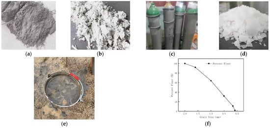
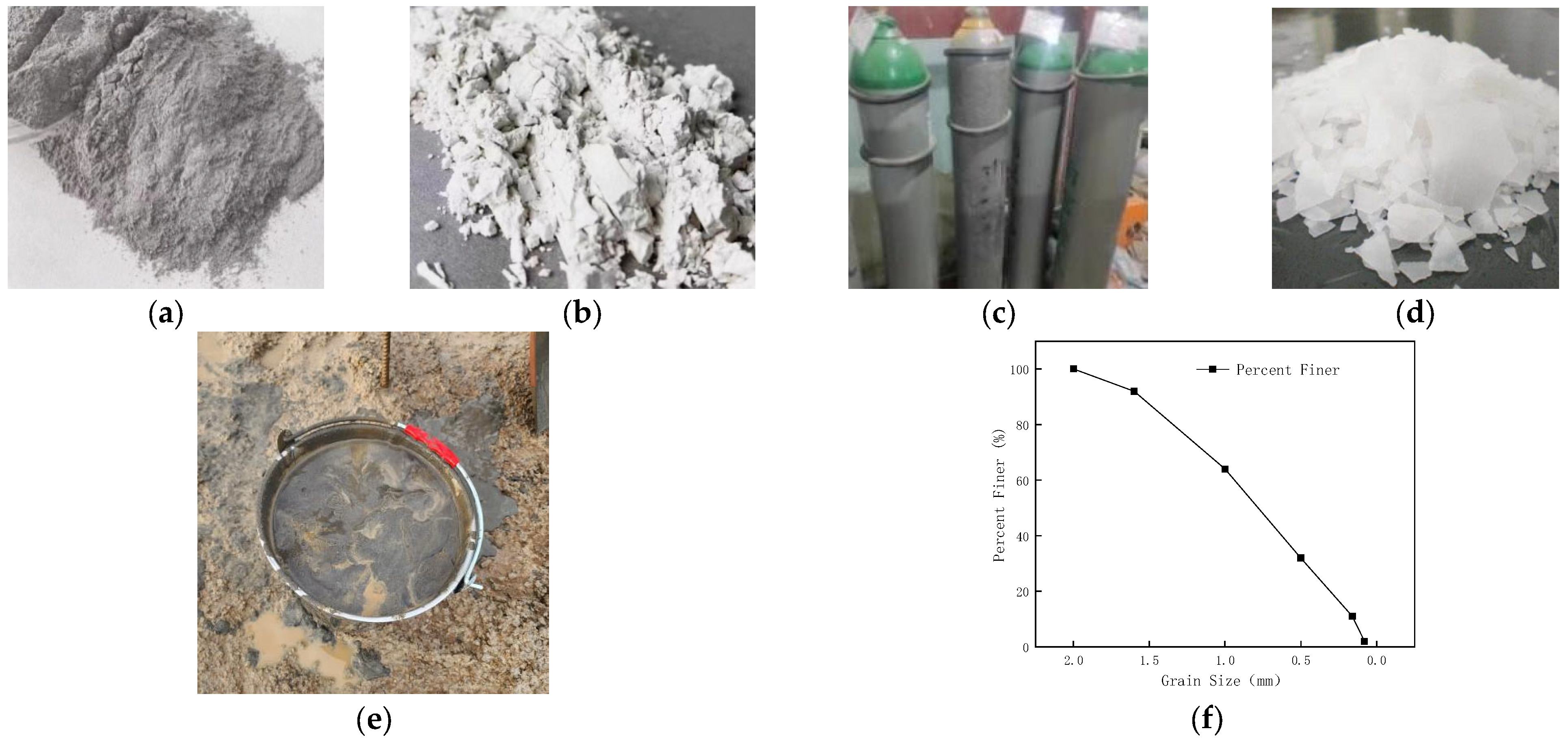
The main raw materials used in this study, including fly ash, GGBS, CO2 gas cylinders, sodium hydroxide, fluid spoil and its particle-size distribution, are illustrated schematically in Figure 1. The chemical composition of the fly ash and the main parameters of the sodium silicate solution are summarized in Table 1 and Table 2.
Figure 1.
Raw materials. (a) Fly ash. (b) GGBS. (c) CO2 cylinder. (d) Solid sodium hydroxide. (e) Flowable slag. (f) Soil particle size distribution.
Table 1.
Chemical composition of fly ash.
Table 2.
Parameters of water glass solution.
3. Test Plan
3.1. Mix Design of Geopolymer Gel Materials
Although a small amount of cement (50 g) is introduced into the geopolymer system in this study, its primary role is to adjust the setting time and improve early-age stability rather than to act as the main binder. The dominant cementitious phases are still C–A–S–H and N–A–S–H gels generated by alkali-activated slag and fly ash, which are responsible for strength development and microstructure formation. The cement content is much lower than that in conventional cement-based systems and does not compromise the core low-carbon objective of replacing Portland cement with geopolymers [30].
GGBS is a latent hydraulic material that rapidly forms C–A–S–H gels under alkali activation, providing early-age strength. Fly ash primarily participates in secondary pozzolanic reactions, improving the fluidity of the paste and contributing to long-term densification. By adjusting the relative contents of GGBS and fly ash, a balance between early strength and workability can be achieved. In this study, a single-factor experimental program is designed to investigate the influence of the GGBS-to-fly ash mass ratio on the workability and mechanical properties of alkali-activated CO2 foamed concrete. The masses of the NaOH solution and sodium silicate solution are fixed at 100 g each, the cement dosage is fixed at 50 g, the CO2 concentration at 40 vol% and the foam volume fraction at 70%. The GGBS-to-fly ash mass ratio is set to 100:0, 75:25, 50:50, 25:75 and 0:100, corresponding to mix IDs D1–D5. This design aims to clarify the effects of different geopolymer precursor compositions on the reactivity, setting time and strength development of CO2 foamed concretes. The mix proportions and test results for each group are summarized in Table 3. These results provide the baseline mix for subsequent multi-factor orthogonal experiments and are important for understanding the strength contribution and microstructural mechanisms of different geopolymer compositions.
Table 3.
Different geopolymer mixture schemes.
3.2. Mix Design of CO2 Foamed Concrete
The factor levels in the orthogonal design were determined by combining (a) feasible operational ranges of the foam generator and CO2 supply on construction sites, (b) preliminary screening tests to ensure foam stability and prevent segregation/bleeding in spoil-rich slurries and (c) literature-reported ranges for alkali-activated binders and foamed concretes. Specifically, the CO2 concentration was set to 40–100% to cover the transition from insufficient carbonation/foaming driving force to potential over-carbonation and bubble coarsening; the foam volume fraction was set to 50–80% to span workable density and pore connectivity regimes for backfilling; the geopolymer dosage was set to 10–25% (by total solids) to balance binder sufficiency, cost and low-carbon substitution; and the alkali activator dosage was set to 5–20% to cover under-activation to excessive alkalinity/viscosity conditions.
Based on the single-factor results, an orthogonal experimental design is conducted to investigate the combined effects of CO2 concentration, foam volume fraction, total geopolymer content and alkali activator dosage on the performance of spoil-based alkali-activated CO2 foamed concrete. Four main control factors are considered: CO2 concentration (A), foam volume fraction (B), geopolymer dosage (C) and alkali activator dosage (D). Each factor is assigned four levels: CO2 concentrations of 40%, 60%, 80% and 100%; foam volume fractions of 50%, 60%, 70% and 80%; geopolymer dosages of 10%, 15%, 20% and 25% (by mass of total solids); and alkali activator dosages of 5%, 10%, 15% and 20%. An L16(44) orthogonal array is adopted to systematically design the 16 combinations. The performance indices include 7-day and 28-day compressive strengths, fluidity and setting times. The detailed orthogonal mix design and test matrix are listed in Table 4.
Table 4.
Orthogonal experiment scheme table.
4. Preparation Procedure
4.1. Preparation of Alkali Activator
Solid NaOH (analytical grade, purity ≥ 96%) is dissolved in deionized water in a polyethylene beaker to prepare a 10 mol/L concentrated solution. This process is highly exothermic, and the solution temperature can rise above 80 °C. The freshly prepared solution is sealed and allowed to stand for 24 h to cool to room temperature (20 ± 2 °C) and to stabilize its chemical activity, thereby avoiding the adverse effects of local over-concentration or overheating on the subsequent geopolymerization reactions.
After standing, the NaOH solution is blended with an industrial sodium silicate solution (modulus ≈ 2.4, SiO2 content 29.8%, Na2O content 13.2%) at a mass ratio of 1:1. A mechanical stirrer is used to mix the solution at 400 rpm for 5 min until a homogeneous and slightly viscous composite alkali activator is obtained. The calculated final modulus (molar ratio of SiO2 to Na2O) of the composite activator is approximately 1.2.
4.2. Preparation of CO2 Foam
First, K12 and HPMC are dissolved in deionized water to prepare a composite foaming solution with a K12 concentration of 1.5 wt% and an HPMC concentration of 0.2 wt%. The composite solution is then poured into a high-shear mechanical foaming device connected to CO2 gas sources of different purities (20%, 40%, 60%, 80% and 100%). The gas flow rate is precisely controlled using a mass flow controller. Under an inlet pressure of 0.3 MPa and a shear rate of 1200 rpm, CO2 foam with a wet density of 50 ± 5 kg/m3 is generated. To ensure stability and foaming efficiency, the prepared foam is used within 5 min.
4.3. Mixing Procedure
A planetary mortar mixer with a capacity of 5 L is used for mixing. The following sequence is strictly followed:
(1) Dry mixing: Pre-treated high-fluidity spoil (fixed mass of 400 g, moisture content ≥ 30%), GGBS, fly ash and 50 g of P.O 42.5 cement are added to the mixing bowl. The mixture is dry-mixed at a low speed (140 ± 5 rpm) for 60 s to ensure a preliminary homogeneity of the solid particles.
(2) Wet mixing with alkali activator: The pre-prepared composite alkali activator is then poured into the mixer. The mixture is stirred at a low speed (140 ± 5 rpm) for 120 s to disperse the viscous activator uniformly. The remaining mixing water is subsequently added, and the mixer speed is increased to high speed (285 ± 10 rpm) for 180 s to fully activate the solid precursors and obtain a homogeneous geopolymer slurry with an adequate fluidity.
(3) Incorporation of CO2 foam: The pre-measured volume of CO2 foam is gently placed on top of the slurry. The mixer is restarted at a low speed (140 ± 5 rpm) and operated for a further 120 s to carefully fold the foam into the slurry. The final mixture is a uniform, creamy and highly flowable CO2 foamed concrete without visible bleeding or large voids.
4.4. Casting and Curing
The fresh foamed mixture is cast into 40 mm × 40 mm × 160 mm three-compartment prismatic molds in a single layer and slightly overfilled to ensure complete filling. The molds are placed on a vibrating table operating at 50 Hz and vibrated for 15 s to remove large entrapped air bubbles and improve compaction. After vibration, the mold surfaces are immediately covered with plastic film to prevent moisture loss, and the specimens are stored at 20 ± 2 °C for 24 h. The specimens are then demolded, and the top surfaces are ground flat.
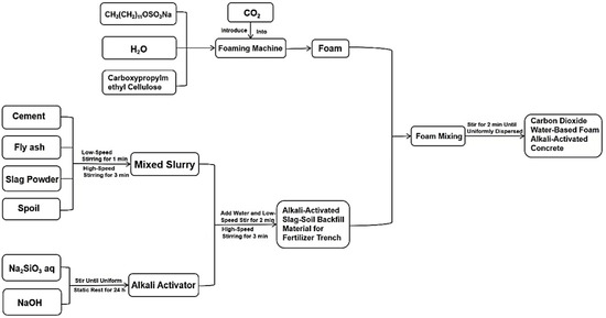
After demolding, the specimens are wrapped with plastic film and transferred to a standard curing chamber with a temperature of 20 ± 2 °C and relative humidity of at least 95%. They are cured to the target ages of 7 d and 28 d for subsequent macro-performance tests and microstructural analyses. The overall preparation procedure is illustrated schematically in Figure 2 and Figure S1.
Figure 2.
Preparation process flowchart.
5. Test Methods
5.1. Fluidity
The fluidity of the fresh mixtures is measured in accordance with the Chinese standard GB/T 2419-2022 “Test method for fluidity of cement mortar” [31], using a flow table. A clean, moistened truncated cone mold is placed at the center of the flow table and fixed. The mold is filled with fresh mixture in two layers; each layer is tamped 15 times with a tamping rod to ensure compaction and to expel trapped air. Excess material is then removed by drawing a straightedge across the top surface of the mold. The mold is immediately lifted vertically and smoothly. The table is dropped 25 times at a frequency of one drop per second. After the mixture has stopped flowing, the spread diameter is measured in two orthogonal directions with a Vernier caliper and the average value is taken as the fluidity of the mixture.
5.2. Compressive Strength
Compressive strength was determined in accordance with GB/T 17671-2021 using 40 × 40 × 160 mm prismatic specimens. The loaded area for compression was 40 × 40 mm (A = 1600 mm2). A servo-controlled testing machine was used under [force-control] at a loading rate compliant with the standard (approximately 2.4 kN/s, equivalent to ~1.5 MPa/s for A = 1600 mm2) until failure. For each mixture, three specimens were tested and the results are reported as means ± standard deviation. Any outlier beyond ±10% of the mean was re-tested. The compressive strength f is calculated as follows:
where f is the compressive strength (Pa), F is the failure load (N) and A is the loaded area of the specimen (40 mm × 40 mm).
f = F/A
5.3. Setting Time
The setting time of the mixtures is determined using a Vicat apparatus in accordance with the Chinese standard GB/T 1346-2022 “Test methods for water requirement of normal consistency, setting time and soundness of the Portland cements” [32]. After mixing, the paste is placed into the Vicat mold. Following compaction and levelling, the mold is immediately transferred to a standard curing box. The initial setting time is measured using the standard Vicat needle (mass 300 ± 1 g, needle diameter 1.13 ± 0.05 mm). Measurements start 30 min after the beginning of mixing and are repeated every 5 min. The time at which the needle penetrates the paste and stops at 4 ± 1 mm above the bottom plate is recorded as the initial setting time. For the final setting time, the mold is inverted and the final setting attachment (with an annular ring) is used. Measurements are taken every 15 min. The time at which only a shallow ring mark is left on the paste surface without penetration (i.e., indentation diameter of approximately 20 mm) is recorded as the final setting time.
5.4. SEM
To investigate the microstructural evolution mechanism, representative specimens with the optimum mix proportions (CO2 concentration 60%, foam volume fraction 80%, geopolymer content 20%, alkali activator dosage 10%) are selected after 28 d of standard curing for SEM observations. Small blocks with dimensions of approximately 10 mm × 10 mm × 5 mm are cut from the core region of the specimens using a precision saw. To terminate further hydration, the samples are immediately immersed in absolute ethanol for 7 d in sealed containers. They are then dried in a vacuum oven at 60 ± 5 °C to a constant mass. Fresh fracture surfaces are sputter-coated with a thin gold film to ensure electrical conductivity. SEM observations are carried out at appropriate accelerating voltages and working distances to examine the micro-morphology, pore structure, ITZ and distribution of the hydration and carbonation products.
The instruments used are shown in Figure S2.
6. Results
6.1. Effect of Geopolymer Composition
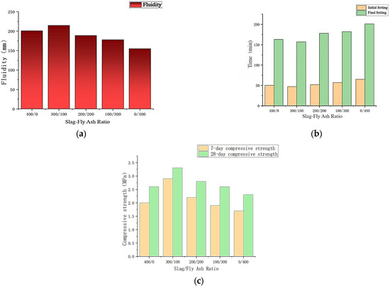
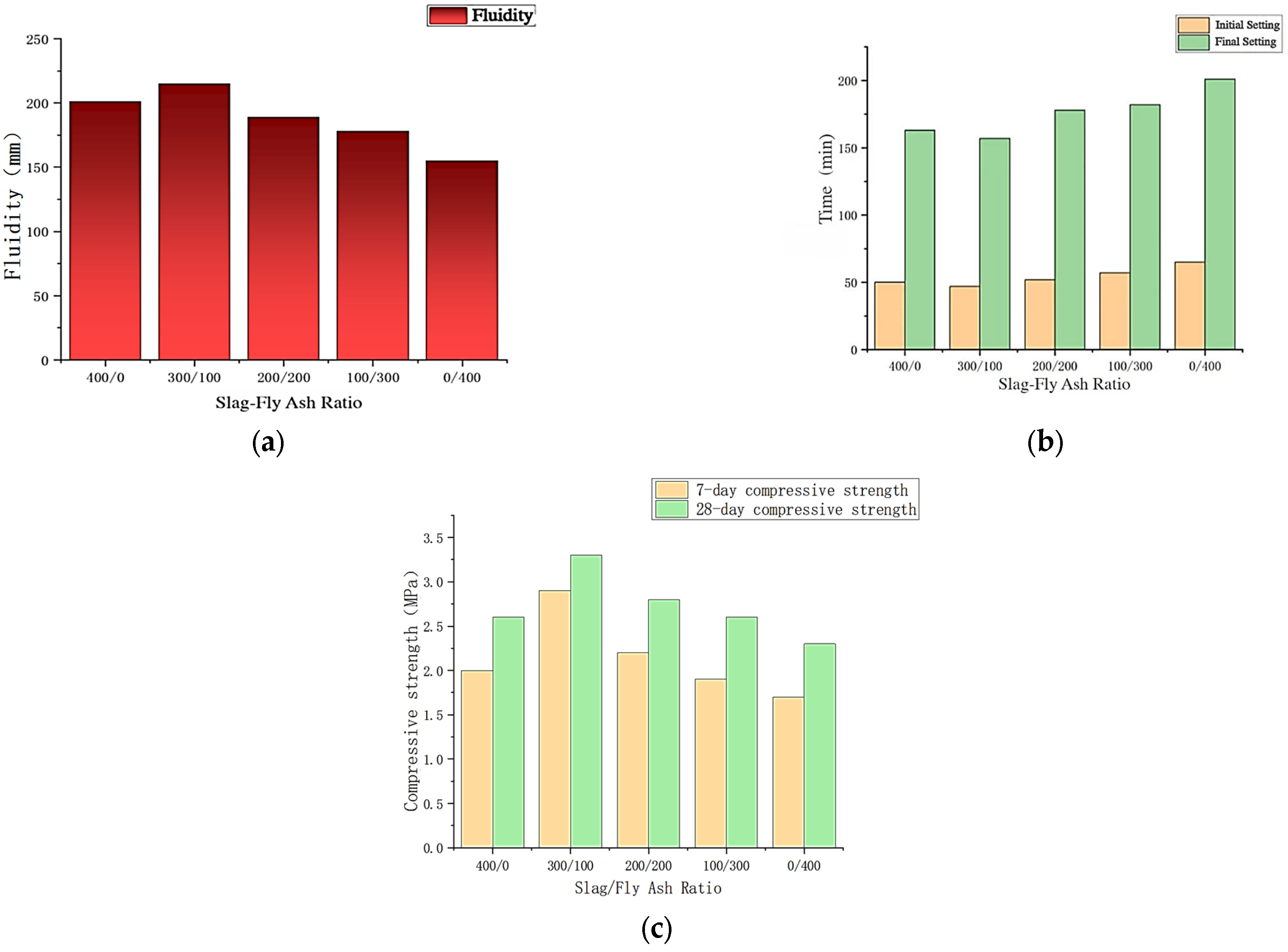
To clarify the isolated influence of geopolymer precursor composition on material performance, other process parameters are kept constant and the effects of the GGBS-to-fly ash mass ratio on the macro-properties of alkali-activated CO2 foamed concrete are systematically investigated. The experimental results are summarized in Table 5 and illustrated schematically in Figure 3.
Table 5.
Experimental results of geopolymers with different proportions.
Figure 3.
Changes in various factors under different geopolymer ratios. (a) Fluidity. (b) Setting time. (c) Compressive strength.
(1) Effect on compressive strength: As the fly ash content increases from 0% to 100%, both 7 d and 28 d compressive strengths first increase significantly and then gradually decrease. When the GGBS-to-fly ash mass ratio is 3:1 (mix D2), the strengths reach their maxima: 2.9 MPa at 7 d and 3.3 MPa at 28 d. Compared with the pure slag system (D1), the 7 d and 28 d strengths increase by 45% and 27%, respectively; relative to the pure fly ash system (D5), the increases are 71% and 43%. This indicates a pronounced synergistic strengthening effect when slag and fly ash are combined at an appropriate ratio (3:1).
The underlying mechanism is that a moderate amount of fly ash (25%) can be activated in the alkaline environment to produce N–A–S–H gels, which interweave with the C–A–S–H gels formed predominantly from slag, optimizing both the composition and spatial configuration of the gel products and thus enhancing strength. However, when the fly ash content exceeds 50%, the supply of Ca2+ ions from slag becomes insufficient, leading to a reduced rate and amount of C–A–S–H formation, which is crucial for early strength. Meanwhile, the reaction of fly ash is relatively slow and cannot compensate for the loss of strength in time. As a result, the overall matrix compactness is reduced and the strength decreases.
(2) Effect on fluidity: The fluidity of the fresh mixtures exhibits a non-linear decreasing trend with increasing fly ash content. When the fly ash content is 25% (D2), the best fluidity of 215 mm is obtained, which is slightly higher than that of the pure slag system (201 mm, D1), representing an increase of about 7%. However, when the fly ash content is further increased to 50% and above, the fluidity decreases markedly, from 215 mm (D2) to 155 mm (D5), a reduction of 28%.
This behavior can be attributed to a combination of effects. At the optimum ratio, the ball-bearing effect of the spherical fly ash particles dominates, reducing the internal friction between particles and improving rheology. When the fly ash content becomes too high, its large specific surface area leads to a greater adsorption of free water, and the micro-filler effect significantly increases the plastic viscosity of the paste. These detrimental effects outweigh the beneficial ball-bearing effect, resulting in a pronounced loss of fluidity.
(3) Effect on setting time: The test data clearly show that fly ash exhibits a marked retarding effect. As its content increases from 0% to 100%, the initial setting time is prolonged from 50 min (D1) to 65 min (D5), and the final setting time from 163 min to 201 min, corresponding to increases of 30% and 23%, respectively. Overall, increasing the fly ash content tends to prolong both the initial and final setting times; however, a slight reduction in the initial setting time is observed at 25% fly ash (D2), which may be associated with particle packing/nucleation effects, followed by a pronounced retardation at higher fly ash contents due to a reduced early-age reactivity.
The main reason lies in the difference in chemical reactivity between slag and fly ash. Slag possesses a latent hydraulic reactivity and can rapidly dissolve and form C–A–S–H gels under alkali activation, playing a dominant role in early setting. Fly ash, however, is a pozzolanic material with a more stable glassy structure; its dissolution and depolymerization rate in an alkaline solution is much slower than that of slag, and the formation of N–A–S–H gels is also sluggish. Therefore, increasing the fly ash content inevitably slows down the overall geopolymerization process and extends the setting time.
In summary, the mix D2 with a GGBS-to-fly ash mass ratio of 3:1 achieves an optimal balance between strength, workability and setting time. It offers the highest compressive strength while maintaining a favorable fluidity and acceptable setting behavior, and is therefore adopted as the baseline geopolymer composition for the subsequent orthogonal tests.
6.2. Effect of Orthogonal Mix Parameters
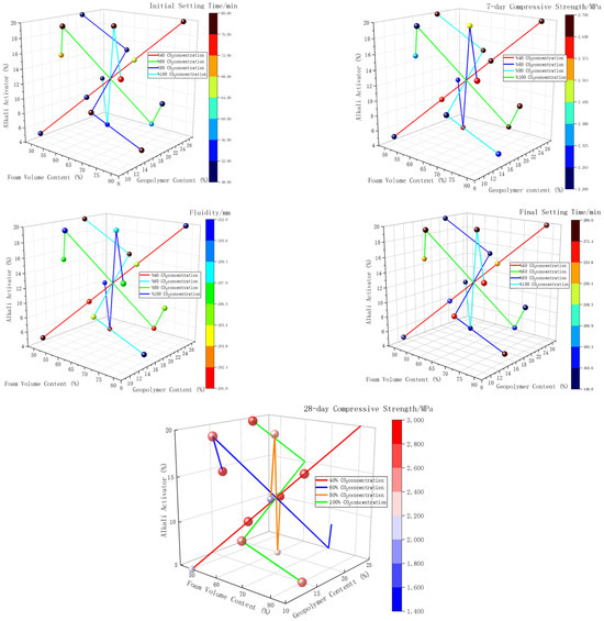
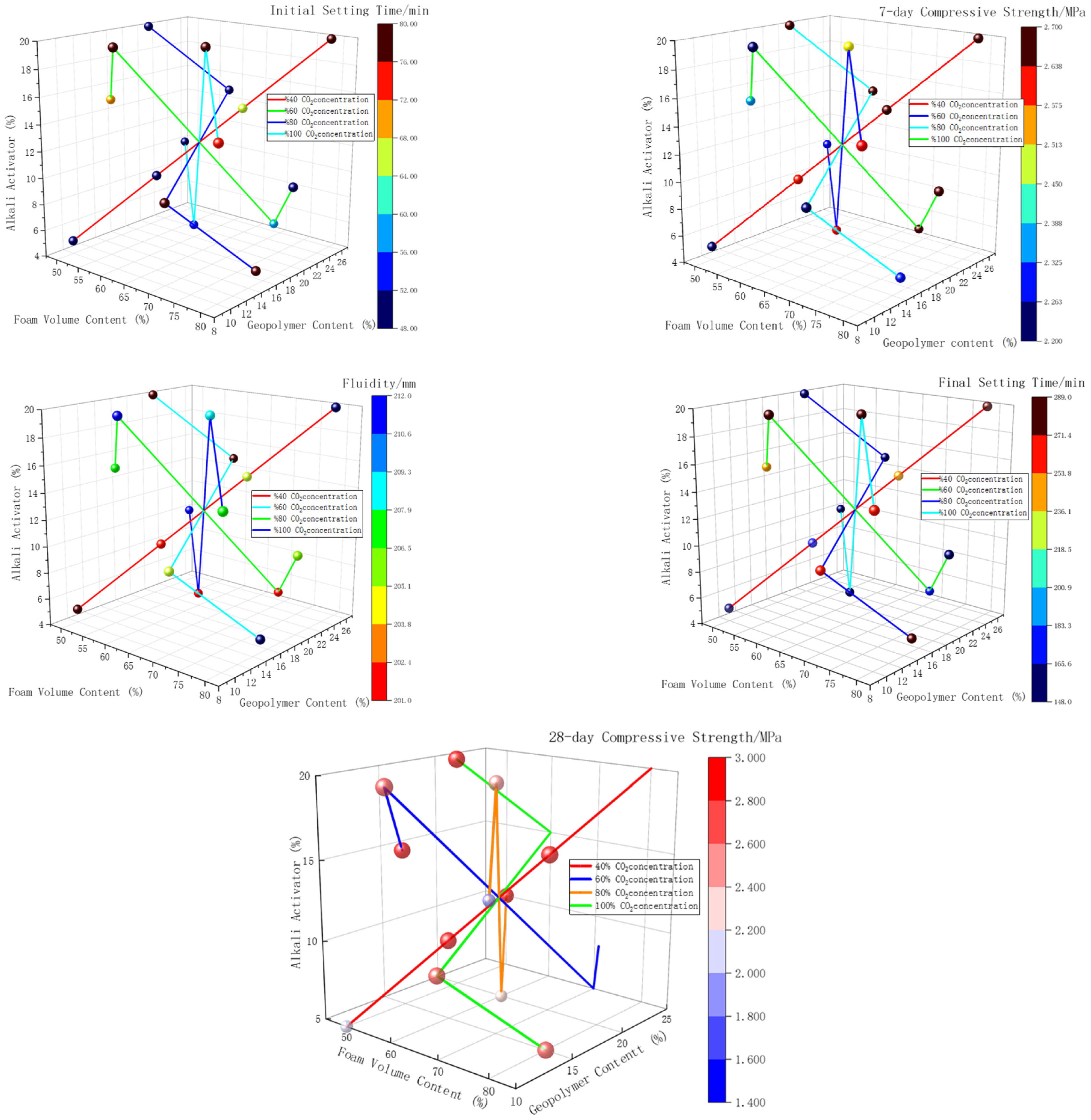
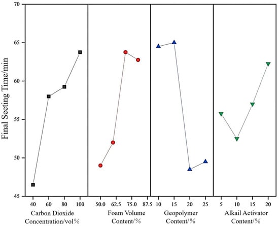
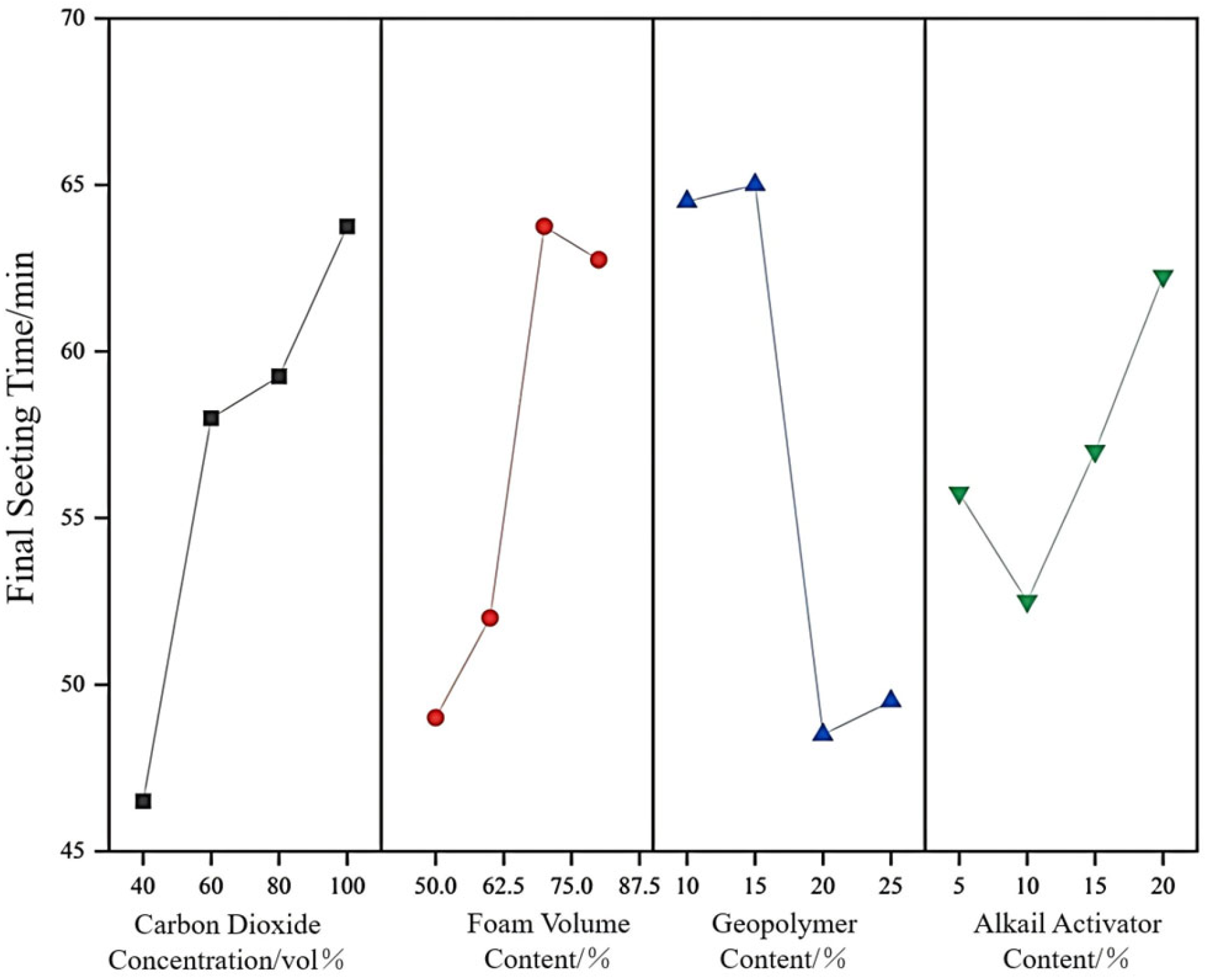
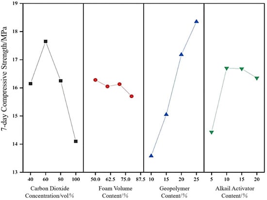
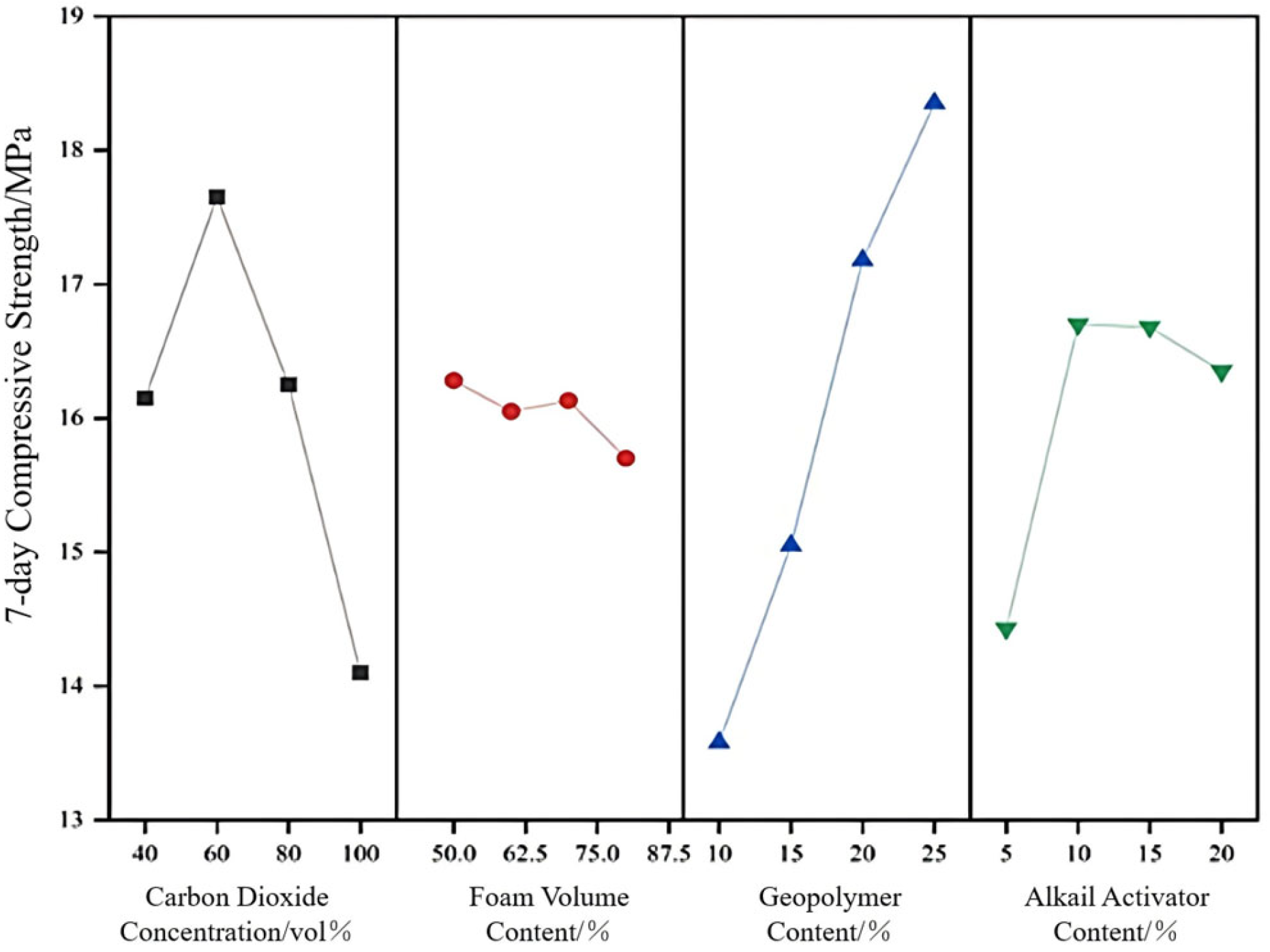
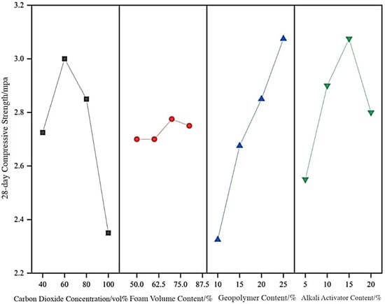
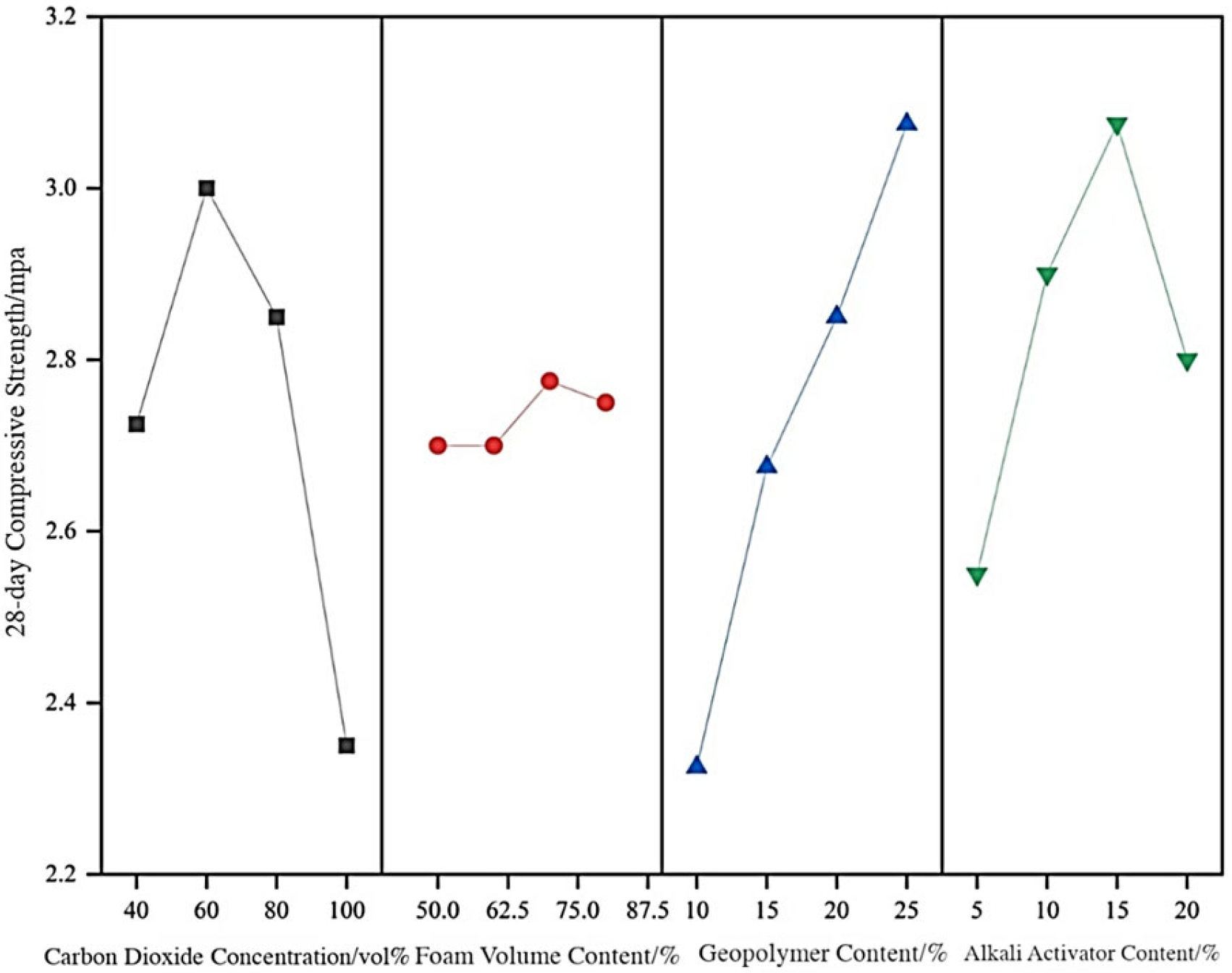
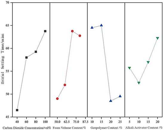
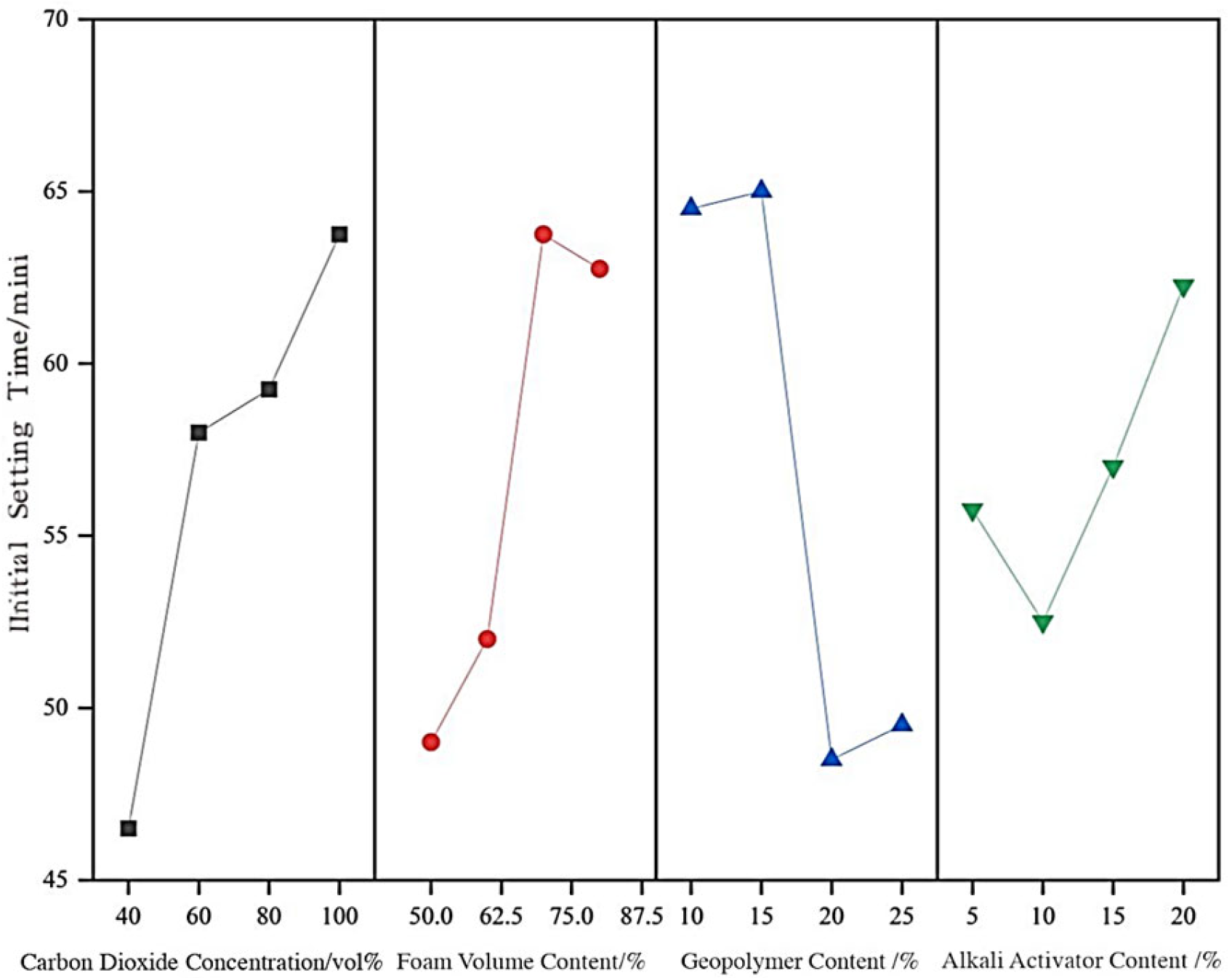
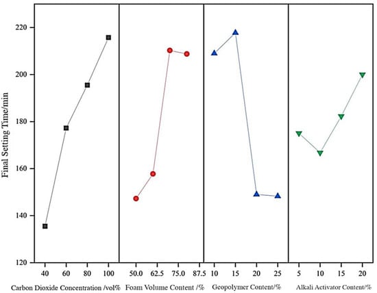
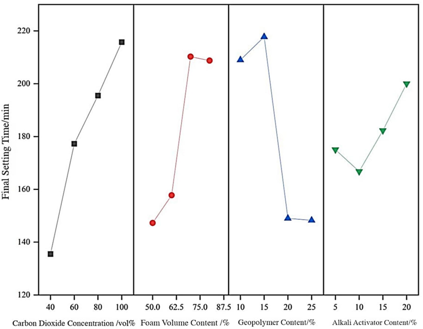
Building on the single-factor experiments, an L16(44) orthogonal design is used to clarify the combined influences of CO2 concentration (A), foam volume fraction (B), total geopolymer content (C) and alkali activator dosage (D) and to identify the optimum mix combination. The test results are summarized in Table 6, and the range analyses are presented in Table 7, Table 8, Table 9, Table 10 and Table 11 and Figure 4, Figure 5, Figure 6, Figure 7, Figure 8 and Figure 9. The color of the line between points represents the concentration of CO2, and the three axes of the three-dimensional spatial coordinate system represent the volume of foam, the total amount of geopolymer and the amount of alkali activator, respectively. The color of the points represents the experimental results.
Table 6.
Results of the orthogonal experiment.
Table 7.
Range analysis table of fluidity.
Table 8.
Range analysis table of 7 d compressive strength.
Table 9.
Range analysis table of 28 d compressive strength.
Table 10.
Range analysis of table initial setting time.
Table 11.
Range analysis table of final setting time.
Figure 4.
Three-dimensional visualization of the orthogonal experimental results.
Figure 5.
Range analysis of fluidity.
Figure 6.
Range analysis of 7 d compressive strength range.
Figure 7.
Range analysis of 28-day compressive strength.
Figure 8.
Range analysis of initial setting time.
Figure 9.
Range analysis of final setting time.
(1) Factor significance and influence patterns
1. Fluidity: According to the range analysis, the factors affecting fluidity can be ranked as A (R = 16.5) > B (R = 15.25) > D (R = 12) > C (R = 9). This indicates that gas- and liquid-phase characteristics are the primary determinants of fluidity. A moderate CO2 concentration of 60% (k2 = 220.75 mm) promotes the formation of fine and stable bubbles, which provide a ball-bearing effect and significantly improve fluidity. The foam volume shows an optimum range (50–60%): when the foam content exceeds 70%, the excessive porosity weakens the paste skeleton and increases viscosity, leading to a decreased fluidity.
2. Compressive strength: For both 7 d and 28 d strengths, the factor ranking is C > A > D > B. Geopolymer dosage is the dominant parameter. When the geopolymer content is 20–25% (k3 = 2.4 MPa; k4 = 2.6 MPa for 7 d strength), a continuous and dense gel skeleton forms, providing the main structural strength. CO2 concentration influences strength via carbonation: at 60% CO2 (k2 = 2.525 MPa at 7 d), carbonate microcrystals precipitate and fill pores, enhancing the strength. However, an excessively high CO2 concentration (100%) coarsens the bubble structure and damages the skeleton, reducing the 7 d strength to 1.825 MPa.
3. Setting time: For both the initial and final setting times, the factor ranking is A > C > B > D. When the CO2 concentration exceeds 80%, rapid carbonation consumes OH− and significantly lowers the system alkalinity, thus slowing down the geopolymerization process and prolonging setting, with the longest final setting time reaching 215.75 min (k4). An increase in the proportion of fly ash in the geopolymer also retards setting due to its lower reactivity.
(2) Interaction and optimum mix confirmation: A strong synergistic effect is observed between CO2 concentration and geopolymer dosage. For example, in group 8 (A2B3C3D2), a moderate CO2 concentration of 60% not only generates a uniform pore structure through physical foaming, but also triggers moderate carbonation, which cooperates with the 20% geopolymer to densify the matrix. As a result, a favorable balance of mechanical performance and workability is achieved, with an 28 d strength of 3.3 MPa and a fluidity of 220 mm.
Considering fluidity, strength and setting time comprehensively, the optimum mix combination is determined to be a CO2 concentration of 60%, a foam volume fraction of 80%, a geopolymer content of 20% and an alkali activator dosage of 10%. This combination, corresponding to one of the orthogonal groups, exhibits the best overall performance and is therefore chosen for microstructural and mechanism studies.
Although formal inferential statistics (e.g., ANOVA or hypothesis testing) are not performed in this work, the repeatability and uncertainty of the experimental results were controlled and qualitatively evaluated to ensure the reliability of the observed trends. For each mixture, key fresh and hardened properties (fluidity, setting time and compressive strength) were measured using at least three replicate specimens/batches under the same curing and testing conditions, and the reported values represent the averaged results. The main sources of experimental variability are associated with (i) the inherent heterogeneity of pipe-jacking spoil, (ii) foam generation stability (bubble size distribution and drainage) and (iii) specimen preparation/compaction and end-surface conditions during compression testing. To minimize these effects, the spoil was homogenized prior to mixing, foam generation parameters were kept constant and the specimen preparation and curing procedures were strictly standardized for all groups. Importantly, the ranking of factor effects obtained from the L16(44) orthogonal design is based on the consistent trend differences between factor levels across multiple groups rather than a single measurement, which improves the robustness for engineering-oriented parameter screening. Therefore, while the present orthogonal analysis primarily provides a practical factor ranking and an optimum window within the tested ranges, further work will incorporate more rigorous statistical inference and expanded repetitions to quantify significance and confidence intervals.”
7. Discussion
7.1. Microstructural Evolution and Synergistic Mechanism
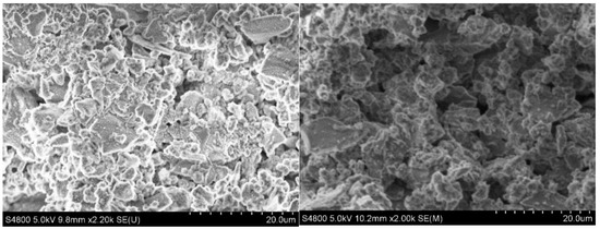
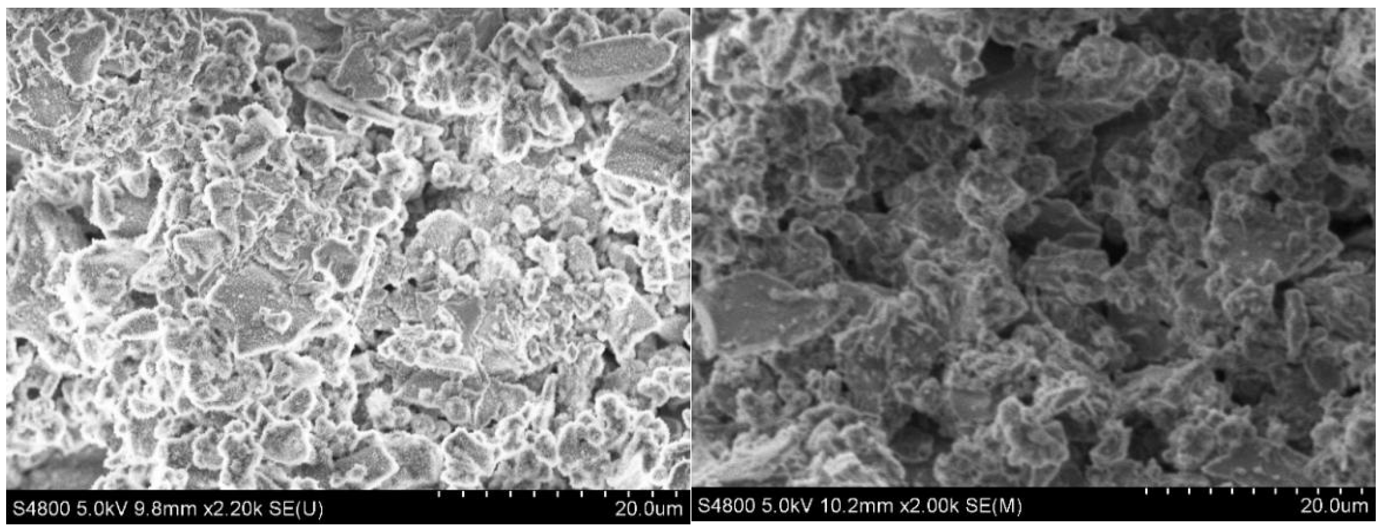
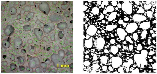
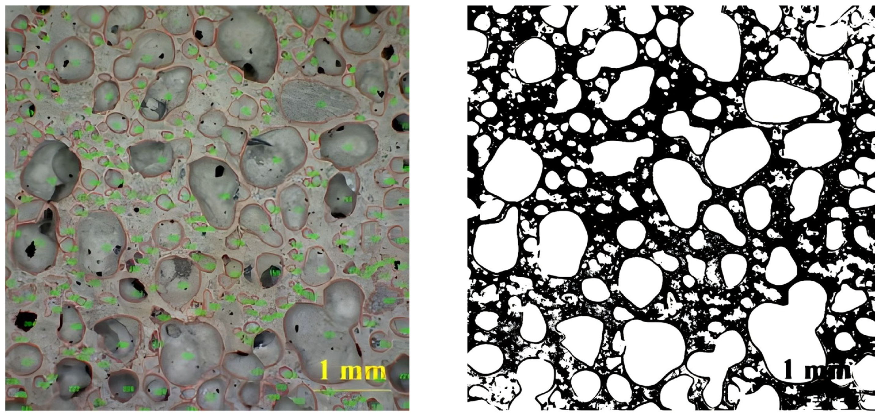
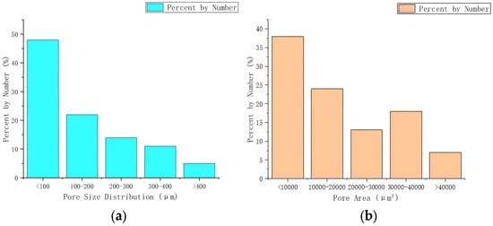
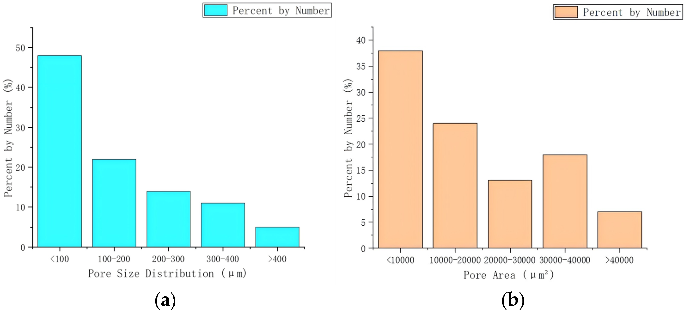
To elucidate the multi-scale role of CO2 in alkali-activated spoil-based foamed concrete, SEM observations (Figure 10) and Image-Pro Plus analyses are carried out on specimens with the optimum mix after 28 d of curing. Combined with the pore size distribution (Figure 11 and Figure 12) and microstructural data (Table 12 and Table 13), the microstructural origin of the macroscopic performance is clarified. The histogram uses the maximum Feret diameter, whereas the average value in Table 13 refers to the equivalent circular diameter calculated from pore area.
Figure 10.
SEM microscopic morphology image.
Figure 11.
Image-Pro Plus microscopic analysis diagram.
Figure 12.
Quantitative statistics chart. (a) Pore size distribution. (b) Pore area distribution.
Table 12.
Microscopic data analysis table.
Table 13.
Analysis of the mean values of microscopic data.
The SEM images show that the internal structure of the specimens is dominated by uniformly distributed closed pores. Quantitative analysis using Image-Pro Plus reveals a porosity of about 23.50%, with most pores in the size range of 100–500 μm. The 200–300 μm interval has the highest frequency, accounting for approximately 42% of the pores. The pore area ranges from 2938.55 to 57,355.52 μm2, with an average of 16,352.98 μm2, and the average pore diameter is about 85.06 μm. This moderate porosity and pore size distribution indicate that CO2 physical foaming has produced a stable three-dimensional bubble network. The uniform fine pores reduce internal friction and provide a pronounced ball-bearing effect, which explains the high fluidity (>210 mm) observed in the macroscopic tests.
At higher magnifications, C–A–S–H and N–A–S–H gels are observed to interweave and form a continuous network skeleton. Abundant nano- to micro-scale carbonate crystals are distributed within the gel network and along the pore walls. These crystals, generated by CO2 carbonation, coexist intimately with the geopolymer gels, forming a “gel–carbonate” composite matrix. The fine carbonate crystals act as micro-fillers, effectively filling gel pores and ITZ defects and greatly improving matrix compactness. This is the fundamental reason why the optimum mix achieves a 28 d compressive strength of 3.3 MPa despite the relatively high porosity.
In particular, the SEM images show that originally loose spoil particles with smooth surfaces are completely wrapped and firmly bonded by the reaction products. This “spoil particle immobilization” transforms otherwise inert waste particles into effective reinforcing inclusions and eliminates potential weak interfaces. As a result, the interfacial structure of the composite is optimized, and the macroscopic mechanical performance becomes more uniform and stable.
Overall, CO2 contributes to performance enhancement through multiple coupled pathways. Physical foaming creates a uniform pore structure that ensures a high fluidity; chemical carbonation generates nano-scale carbonates that work synergistically with geopolymer gels to construct a dense matrix; and the alkali-activated environment fixes spoil particles within the gel network. These coupled processes collectively form a stable “gas–solid–soil” composite structure, which is the core mechanism enabling the high performance and resource utilization in the proposed material.
The proposed multi-scale mechanism is herein framed as an evidence-linked interpretation anchored in the SEM observations and the macroscopic trends reported in Section 6.1. First, mixtures with a higher foam volume fraction exhibit a lower density and reduced compressive strength, which is consistent with the SEM-observed increase in pore population and the reduced continuity/thickness of the solid skeleton and pore walls; conversely, mixes showing more uniform and predominantly closed pores with continuous pore walls correspond to an improved strength retention at a comparable workability. Second, increasing the CO2 concentration promotes the formation of fine carbonate precipitation and the partial infilling/lining of pore walls and inter-particle regions observed in SEM, which provides a microstructural basis for the observed enhancement in early-age stability and/or strength at comparable foam contents by densifying the matrix and reducing defects. Third, an increased geopolymer/activator dosage leads to more continuous gel products and a stronger bonding/encapsulation around spoil particles in SEM, which explains the improved setting stability and strength through particle immobilization and a more integrated load-bearing framework. Taken together, the SEM features (pore wall continuity, degree of infilling/densification and gel continuity at interfaces) provide a consistent microstructural rationale for the measured trade-off between flowability, setting behavior and strength across the tested parameter ranges, thereby strengthening the microstructure–property linkage.
7.2. Composition–Structure–Property Relationship Model
Based on the macro-performance tests and microstructural analyses, a composition–structure–property relationship model is proposed for alkali-activated high-fluidity spoil CO2 foamed concrete, illustrating how key components govern microstructural formation and thereby determine macroscopic properties.
(1) Composition–structure relationships: GGBS and fly ash act as the core cementitious precursors. Their dosages and ratio directly control the quantity and type of gels formed. GGBS supplies Ca2+ and promotes C–A–S–H formation, dominating early strength, while fly ash mainly produces N–A–S–H and refines the structure at later ages. The CO2 concentration and foam volume fraction, together with the foaming system, determine the porosity and pore size distribution through physical foaming and the amount and distribution of carbonates through chemical carbonation. The alkali activator dosage and modulus regulate the reaction kinetics and the rate of gel network formation, thereby controlling the development of matrix compactness and setting behavior.
(2) Structure–property relationships: The continuous geopolymer gel network and carbonate-filled ITZs constitute the load-bearing skeleton and directly determine the compressive strength. Uniform fine pores reduce internal friction and improve fluidity, while a closed-pore structure helps maintain durability. The rate of gel formation and carbonation, together with ion transport, affects the evolution of the internal chemical environment and thus controls the setting process. Therefore, strength, fluidity and setting time are unified responses of the multi-scale microstructure.
(3) Synergistic optimization mechanism: The optimal performance is achieved when the contributions of all components reach a synergistic balance. Through rational mix design, the timing and spatial distribution of CO2 physical foaming, chemical carbonation and geopolymer gel formation are coordinated, leading to a stable multi-scale structure composed of gas (closed pores), solid (dense gels and carbonates) and soil (immobilized spoil particles). The experimentally determined optimum window—a CO2 concentration of 60–80%, foam volume fraction of 70–80%, geopolymer content of about 20% and alkali activator dosage of about 10%—is a manifestation of this synergy and yields balanced mechanical performance, workability and setting characteristics.
8. Conclusions
Focusing on the challenges of treating spoil from pipe-jacking in water-rich sandy strata—especially the difficulty of disposal and low resource utilization—this study proposes a novel collaborative treatment method based on alkali activation and CO2 foaming and successfully prepares an alkali-activated high-fluidity spoil CO2 foamed concrete with tunable properties. The main conclusions are as follows:
(1) A feasible technical route for the co-treatment and performance control of fluid spoil is established. Industrial solid wastes (GGBS and fly ash) are used as geopolymer precursors to build a gel skeleton via alkali activation, while CO2 water-based foam is introduced for collaborative modification. The proposed route enables in situ resource utilization and the efficient solidification of high-moisture, complex-composition fluid spoil, providing a concrete technical scheme for “treating waste with waste” and transforming spoil into useful products.
(2) The influence laws of key mix parameters on macro-properties are clarified and an optimal mix window is identified. Single-factor and orthogonal tests show that geopolymer content is the primary factor controlling the compressive strength; the CO2 concentration and foam volume fraction mainly govern fluidity, and both the alkali activator dosage and CO2 concentration jointly affect the setting time. The optimum performance is achieved with a CO2 concentration of 60–80%, foam volume fraction of 70–80%, total geopolymer content of about 20% and alkali activator dosage of about 10%, under which the material exhibits high fluidity (>210 mm), moderate strength (28 d strength > 3.0 MPa) and reasonable setting times.
(3) From a microstructural perspective, a multi-scale synergistic mechanism of CO2 “physical foaming–chemical carbonation–spoil particle immobilization” is revealed. SEM observations show that CO2 physical foaming produces uniform closed pores that enhance fluidity, while CO2 carbonation generates nano-scale carbonate crystals that fill gel pores and ITZ defects, improving matrix compactness. Meanwhile, alkali-activated gels encapsulate and fix spoil particles, eliminating weak interfaces and forming a stable “gas–solid–soil” composite structure.
(4) A composition–structure–property relationship model is established and verified. The macroscopic properties of the material are shown to be direct manifestations of its microstructure, which in turn is governed by the geopolymer composition, CO2 foam system and alkali activator through coupled reactions. The optimum mix essentially corresponds to a spatiotemporal matching point at which physical foaming, chemical carbonation and geopolymerization are synchronously coordinated. This work not only develops a high-performance, low-carbon foamed concrete, but also provides theoretical and technical support for the high-value, low-cost resource utilization of fluid spoil in applications such as foundation backfilling and trench filling.
Supplementary Materials
The following supporting information can be downloaded at: https://www.mdpi.com/article/10.3390/buildings16071396/s1, Figure S1: Preparation process; Figure S2: Test instruments.
Author Contributions
Conceptualization, L.Z.; methodology, H.G. and P.Z.; software, X.Z.; validation, P.Z.; formal analysis, J.Y. and X.Z.; investigation, X.Z. and L.Z.; resources, P.Z.; writing—original draft, J.Y.; writing—review and editing, P.Z.; visualization, L.Z.; supervision, H.G. and L.Z.; project administration, J.Y.; funding acquisition, J.Y. and H.G. All authors have read and agreed to the published version of the manuscript.
Funding
This study was funded by the State Grid Jiangsu Electric Power Co, Ltd. technology project (Grant No. J2024130).
Data Availability Statement
The datasets used and/or analyzed during the current study are available from the corresponding author upon reasonable request.
Conflicts of Interest
Authors Jiejun Yuan, Hairong Gu and Long Zhang were employed by the company State Grid Jiangsu Electric Power Co., Ltd. Author Xiao Zhang was employed by the company Xuzhou Power Supply Branch of State Grid Jiangsu Electric Power Co., Ltd. The remaining authors declare that the research was conducted in the absence of any commercial or financial relationships that could be construed as potential conflicts of interest.
References
- Tan, M. Synergistic and Environmental Impacts of Industrial Solid Waste and Cement Clinker in Shield Muck Solidification: A Case Study in Shijiazhuang City. Sustainability 2025, 17, 8743. [Google Scholar] [CrossRef] [Scilit]
- Sharghi, M.; Jeong, H. The Potential of Recycling and Reusing Waste Materials in Underground Construction: A Review of Sustainable Practices and Challenges. Sustainability 2024, 16, 4889. [Google Scholar] [CrossRef] [Scilit]
- Huang, B.; Wang, X.; Kua, H.; Geng, Y.; Bleischwitz, R.; Ren, J. Construction and demolition waste management in China through the 3R principle. Resour. Conserv. Recycl. 2018, 129, 36–44. [Google Scholar] [CrossRef] [Scilit]
- Zhang, J.; Li, H.; Yang, H.; Wang, H.; Han, S. Review of research on resource utilization technology of slag from shield tunneling. China Foreign Highw. 2022, 42, 1–11. [Google Scholar] [CrossRef]
- Wang, S.; Zhan, Y.; Yang, X.; Fu, X.; Ling, F. Solidification Mechanism and Quality Evaluation of Shield Tunnel Slag in Silty Clay Soil. J. Beijing Univ. Technol. 2021, 43, 710–718. [Google Scholar]
- Xu, F.; Jiang, C.; Zhang, S.; Yang, D.; Li, S. Experimental Study on Solidification of Shield Tunnel Slag by Alkali-Activated Slag and Soil Pressure Balance. J. Undergr. Space Eng. 2022, 18, 849–859. [Google Scholar] [CrossRef]
- Zhou, X.; Sun, X.; Li, Y.; Liu, H.; Liang, S. Study on Efficient Dewatering and Volume Reduction Treatment of Shield Tunnel Slag Based on DME Phase Change. Mod. Urban Rail Transit 2021, S01, 46–50. [Google Scholar] [CrossRef]
- Zhang, Q.; Zhao, Y.; Zhang, D.; Chen, J.; Lu, J.; Zhang, Y. Study on Green and Efficient Dewatering of Shield Tunnel Slag Using Liquid DME-TTFP. Tunn. Constr. 2023, 43, 178–185. [Google Scholar]
- Xiao, J.; Shen, J.; Duan, Z.; Zhou, Y.; Ren, F.; Xiao, X. Basic problems and low-carbon technology paths for the resource utilization of engineering waste soil. Sci. Bull. 2023, 68, 2722–2736. [Google Scholar]
- Liu, Q.; Wang, Y.; Sun, C.; Cheng, S.; Yang, C. Carbon sequestration and mechanical properties of foam concrete based on red mud pre-carbonation and CO2 foam bubbles. Constr. Build. Mater. 2024, 426, 135961. [Google Scholar] [CrossRef] [Scilit]
- Davidovits, J. Geopolymers: Inorganic polymeric new materials. J. Therm. Anal. 1991, 37, 1633–1656. [Google Scholar] [CrossRef] [Scilit]
- Shi, C.; Jiménez, A.F.; Palomo, A. New cements for the 21st century: The pursuit of an alternative to Portland cement. Cem. Concr. Res. 2011, 41, 750–763. [Google Scholar] [CrossRef] [Scilit]
- Provis, J.L.; Bernal, S.A. Geopolymers and related alkali-activated materials. Annu. Rev. Mater. Res. 2014, 44, 299–327. [Google Scholar] [CrossRef] [Scilit]
- Yu, X.; Shi, J.; He, Z.; Yalçınkaya, Ç.; Revilla-Cuesta, V.; Gencel, O. Review of the materials composition and performance evolution of green alkali-activated cementitious materials. Clean Technol. Environ. Policy 2023, 25, 1439–1459. [Google Scholar] [CrossRef] [Scilit]
- Andrew, R.M. Global CO2 emissions from cement production. Earth Syst. Sci. Data 2018, 10, 195–217. [Google Scholar] [CrossRef] [Scilit]
- Monkman, S.; Shao, Y. Carbonation curing of slag-cement concrete for binding CO2 and improving performance. J. Mater. Civ. Eng. 2006, 18, 768–776. [Google Scholar] [CrossRef] [Scilit]
- Ta, X.; Wan, Z.; Zhang, Y.; Qin, S.; Zhou, J. Effect of carbonation and foam content on CO2 foamed concrete behavior. J. Mater. Res. Technol. 2023, 23, 6014–6022. [Google Scholar] [CrossRef] [Scilit]
- Liu, X.; Liu, X.; Zhang, Z.; Ai, X. Effect of carbonation curing on the characterization and properties of steel slag-based cementitious materials. Cem. Concr. Compos. 2024, 154, 105769. [Google Scholar] [CrossRef] [Scilit]
- Namsone, E.; Šahmenko, G.; Korjakins, A. Durability properties of high performance foamed concret. Procedia Eng. 2017, 172, 760–767. [Google Scholar] [CrossRef] [Scilit]
- Wang, D.; Wu, K. Study on Preparation and Properties of Alkali Activated Slag-Gold Tailings Based Foam Concrete. Min. Res. Dev. 2023, 43, 216–222. [Google Scholar] [CrossRef]
- Wei, X.; Li, J.; Shi, H.; Cao, Y.; Liu, G. Experimental study on CO2 sequestration performance of alkali activated fly ash and ground granulated blast furnace slag based foam concrete. Constr. Build. Mater. 2022, 314, 125542. [Google Scholar] [CrossRef] [Scilit]
- Łach, M. Geopolymer Foams-Will They Ever Become a Viable Alternative to Popular Insulation Materials?—A Critical Opinion. Materials 2021, 14, 3568. [Google Scholar] [CrossRef] [Scilit]
- Lamaa, G.; Duarte, A.P.C.; Silva, R.V.; de Brito, J. Carbonation of Alkali-Activated Materials: A Review. Materials 2023, 16, 3086. [Google Scholar] [CrossRef] [Scilit]
- Kim, K.W.; Lim, H.M.; Yoon, S.-Y.; Ko, H. Fast-Curing Geopolymer Foams with an Enhanced Pore Homogeneity Derived by Hydrogen Peroxide and Sodium Dodecyl Sulfate Surfactant. Minerals 2022, 12, 821. [Google Scholar] [CrossRef] [Scilit]
- Xue, Q.; Zhang, L.; Mei, K.; Li, X.; Wang, Y.; Cheng, X.; Fu, X. Thermal conductivity and pore structure analysis of alkali-activated foam cement with supercritical CO2 modified slag: Feasibility evaluation for geothermal applications. Constr. Build. Mater. 2022, 347, 128506. [Google Scholar] [CrossRef] [Scilit]
- Liu, J.; Li, W.; Wang, L.; Fan, J.; Liu, Q.; Cao, X.; Cheng, W.; Wang, G.; Guan, T.; Song, C. Preparation of alkali-activated slag based foam concrete and feasibility study on CO2 sequestration. China Min. Mag. 2024, 33, 218–225. [Google Scholar]
- Lin, J.; Wang, S.; Yu, H.; Ye, S.; Mao, J.; Chen, S.; Liu, Y.; Yan, D. Carbonation property analysis and carbonation process modeling of GGBFS-based foam alkali-activated binder. Cem. Concr. Compos. 2026, 167, 106446. [Google Scholar] [CrossRef] [Scilit]
- Bai, Y.; Chen, Y.; Chen, Y. Multifunctional Composite: Enhancing Mechanical Properties and Electromagnetic Wave Absorption Performance of Alkali-Activated Steel Slag Foam Concrete. JOM 2025, 77, 8497–8510. [Google Scholar] [CrossRef] [Scilit]
- Rostami, V.; Shao, Y.; Boyd, A.J. Carbonation curing versus steam curing for precast concrete production. J. Mater. Civ. Eng. 2012, 24, 1221–1229. [Google Scholar] [CrossRef] [Scilit]
- Qiu, Z.; Bao, S.; Zhang, Y.; Huang, M.; Lin, C.; Huang, X.; Chen, Y.; Ping, Y. Effect of Portland cement on the properties of geopolymers prepared from granite powder and fly ash by alkali-thermal activation. J. Build. Eng. 2023, 76, 107363. [Google Scholar] [CrossRef] [Scilit]
- GB/T 2419-2022; Method for Determining the Fluidity of Cement Mortar. China Standards Press: Beijing, China, 2022.
- GB/T 1346-2022; Test Method for Standard Consistency Water Requirement, Setting Time and Soundness of Cement. China Standards Press: Beijing, China, 2022.

Disclaimer/Publisher’s Note: The statements, opinions and data contained in all publications are solely those of the individual author(s) and contributor(s) and not of MDPI and/or the editor(s). MDPI and/or the editor(s) disclaim responsibility for any injury to people or property resulting from any ideas, methods, instructions or products referred to in the content. |
© 2026 by the authors. Licensee MDPI, Basel, Switzerland. This article is an open access article distributed under the terms and conditions of the Creative Commons Attribution (CC BY) license.