Abstract
This study investigates the static mechanical behavior of a novel eco-friendly high-performance concrete (HPC) reinforced with fibers under different moisture conditions, reflecting the humidity variations commonly encountered in engineering practice. Three saturation levels—natural, dry, and water saturated—were considered. The optimal dosages of basalt and glass fibers were first identified through tests in the natural state, and empirical relationships between fiber volume fraction, compressive strength, and fracture energy were established. Comparative experiments were then conducted at the optimal dosages under varying saturation conditions. Results show that basalt fiber provides superior compressive strength, exceeding that of glass fiber by 0.86% in the dry state and 10.66% in the saturated state. Conversely, glass fiber exhibits a greater enhancement in flexural strength, with improvements of 14.91% and 3.38% over basalt fiber under dry and saturated conditions, respectively. Although preliminary models were proposed to correlate fiber volume fraction with strength in dry and saturated environments, their predictive accuracy proved limited. Overall, the findings highlight the distinct reinforcing effects of basalt and glass fibers on HPC under different moisture conditions, offering guidance for the design and application of fiber-reinforced recycled concrete in humid service environments.
1. Introduction
Concrete is one of the most globally prevalent building materials, celebrated for its versatility, durability and strength. However, with the evolution of civil engineering, standard-strength concrete is insufficient for meeting the demands posed by complex structures and their environments. High-performance concrete (HPC) has emerged as a standout in modern construction for its enhanced mechanical properties, durability and environmental sustainability. HPC is designed to withstand extreme conditions, including harsh environmental exposure, heavy loads and shrinkage, which are common in infrastructure applications such as bridges, high-rise buildings, and industrial structures [1,2,3]. In large-scale hydraulic concrete structures such as dams, long-term exposure to environmental water results in high moisture conditions. The sections directly in contact with water remain saturated, while even the interior regions, though not directly exposed, often exhibit high water content due to the large volume of the structure, which restricts internal moisture diffusion and evaporation. Similarly, urban sewage pipelines and related concrete infrastructures, which are continuously immersed during the long-term storage and transportation of wastewater, also remain in a saturated state. In contrast, in arid regions such as deserts, concrete pavements are typically subjected to prolonged dry conditions. The ability to customize concrete mixes to meet specific performance criteria makes HPC the preferred choice for engineers and architects seeking to create structures that will stand the test of time.
HPC is characterized by improved strength, durability, and workability through a combination of optimized material selection and advanced mixing techniques. Fiber incorporation has recently gained plenty of attention as a method to enhance concrete performance among various additives and reinforcement techniques. Fibers such as steel [4], polypropylene [5], glass [6], and synthetic fibers [7] can enhance the tensile strength, ductility, and crack resistance of concrete, thus playing a crucial role in developing high-performance materials.
Ahmad et al. [8] reported that glass fibers (GF) enhance the strength and durability of concrete but reduce its workability. A typical optimal dosage is recommended at 2.0%. However, for higher GF dosages (exceeding 2.0%), a higher amount of superplasticizer is advised. Ali et al. [9] found that 50% recycled coarse aggregate (RCA) concrete with 0.5% GF exhibited superior overall mechanical properties (compressive, splitting tensile, and flexural strength) compared with conventional natural coarse aggregate (NCA) concrete. Furthermore, both 50% RCA and 100% RCA concretes with 0.25% GF showed higher splitting tensile and flexural strength than ordinary NCA concrete.
Zhou et al. [10] indicated that even a small dosage of basalt fiber (BF) can significantly improve the mechanical properties and resistance to salt-frost damage of cement mortar under unilateral salt-frost attack. Cement mortar containing 1.2 kg/m3 of BF demonstrated excellent compressive strength, flexural strength, and durability. Wang et al. [11] investigated a bundle-shaped spliced basalt fiber (BSBF) with strong bonding and good dispersion, as well as two surface-modified chopped basalt fibers (SCBF-I and SCBF-II). Based on performance tests, the optimal dosage of 12 mm BSBF (BSBF-12) was determined to be 0.3 vol%. At this dosage, the compressive strength, splitting tensile strength, flexural strength, and flexural toughness index of the concrete increased by 10.39%, 61.16%, 13.33%, and 50.85%, respectively. Moreover, different dosages of BSBF-12 also improved the durability of concrete to varying degrees.
Bencardino et al. [12] investigated the mechanical performance of mortar incorporating wastepaper sludge-derived cellulose fibers. They found that, regardless of the manufacturing process, the mechanical properties of cellulose fiber mortar were comparable to those of mortar with 0% waste content, indicating that the inclusion of cellulose fibers does not compromise mechanical performance but enhances environmental benefits.
Water saturation plays a vital role in determining the mechanical characteristics of concrete. The presence of water in the concrete matrix affects the hydration process, influencing the microstructure, which in turn affects the mechanical behavior of the material. Understanding how water saturation affects the performance of HPC is critical to optimizing its use in a variety of construction applications. Jin et al. [13] studied the quantitative effect of water content on the overall mechanical properties of water-saturated concrete. Compared with dry concrete, saturated water pores limit the deformation of the surrounding concrete matrix into pores, increasing the overall Poisson’s ratio and elastic modulus of concrete. The moisture in the pores of concrete materials has a significant impact on its tensile strength, which should not be overlooked in design.
Moreover, cement is considered an environmentally unfriendly, resource-intensive material that is difficult to recycle. In typical production scenarios, the manufacturing of ordinary HPC materials requires the addition of a large amount of cement, significantly increasing the economic and environmental costs of HPC materials, and thereby hindering their broader application and efficiency. To address this issue, recent years have seen some optimization of HPC’s material composition, mainly through the partial replacement of raw materials—such as cement, silica fume, and fine quartz sand—with industrial waste like fly ash, slag, wind-blown sand, and waste rubber [14,15,16]. However, research and systematic investigations on the static mechanical performance of such new HPC and fiber-reinforced concrete under varying moisture saturation levels remain relatively limited. Therefore, more comprehensive and in-depth studies on the static mechanical characteristics of eco-friendly HPC materials are still required.
In this article, a novel eco-friendly HPC material is put forward, in which fly ash and ultrafine slag partially (approximately 20%) replace cement. For fiber reinforcement, two various fiber types were considered: basalt fiber, widely adopted in concrete reinforcement, and glass fiber, which is less studied in the literature but is more affordable. An experimental comparison was conducted. To study the effects of fiber type, fiber content, and different moisture saturation levels on the static mechanical characteristics of HPC material, a series of compressive, splitting tensile, and three-point bending tests was first conducted under natural conditions using two types of fibers at five different fiber volume fractions. The optimal dosages of both fibers were determined, and predictive equations were established between the fiber volume fraction and the corresponding mechanical strengths, toughness, and energy dissipation capacity of the concrete. Finally, the mechanical parameters of concrete at the optimal fiber dosage were evaluated under different saturation levels.
2. Experimental Setup
2.1. Raw Materials
In this experiment, nine batches of high-performance concrete (HPC) samples were prepared with identical mix compositions and proportions, but incorporating two different types of fibers—glass fiber (GF) and basalt fiber (BF)—at varying volume fractions (0%, 1%, 1.5%, and 2%). The effects of fiber type and dosage on the static mechanical properties of HPC under different moisture conditions were investigated. Images and parameters of the two fibers are presented in Figure 1 and Table 1.
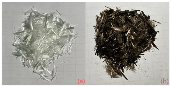
Figure 1.
Images of fibers: (a) glass fiber; (b) basalt fiber.

Table 1.
Presents the sizes and mechanical characteristics of basalt and glass fibers.
Table 2 lists the mix proportions of the high-performance concrete (HPC) used in this study, along with those reported by other researchers. Four cementitious materials, namely, ordinary Portland cement of national standard grade 52.5P.П type (particle size 20–30 μm, density 3.17 g/cm3, specific surface area 0.385 m2/g), Class I fly ash (density: 2.6 g/cm3, residue on 45 μm sieve: 8%), and Chinese standard S105 [17] ground granulated blast furnace slag (GGBFS) (density: 3.1 g/cm3, specific surface area: 0.429 m2/g, 28-day activity index: 98.5%), were utilized as binders in this study. The chemical composition and ignition loss of silica fume, fly ash and ultrafine blast furnace slag are detailed in Table 3. Fine aggregate is selected as river sand with a particle size of less than 0.6 mm and a fineness modulus of 2.4. All concrete mixes incorporate polycarboxylate high-range water reducer (HRWR) from Hunan Zhongyan Technology Co., Ltd., Zhuzhou, China, which ensures the workability of concrete and enhances the early concrete strength.

Table 2.
Compositions and mix ratio of HPCCs (kg/m3).

Table 3.
Chemical content (%) and LOI of three alternative ingredients.
As illustrated in Table 2, compared with traditional HPC [18,19,20,21], the current HPC substitutes a portion of the cement with ultrafine basalt furnace slag and fly ash mineral admixtures. Blast furnace slag is a solid waste formed during the ironmaking process in blast furnaces from the non-volatile components of the ore’s gangue, ash from the fuel, and flux (usually limestone). Research and experiments have demonstrated that incorporating an appropriate amount of blast furnace slag can enhance the tensile, flexural, and compressive strength as well as the elastic modulus of concrete. Fly ash, on the other hand, is a fine ash collected from flue gases after coal combustion, constituting the main solid waste discharged by coal-fired power plants. In this study, fly ash and ultrafine slag were incorporated as supplementary cementitious materials to reduce the usage of cement and silica fume, thereby recycling industrial waste and protecting the environment. Additionally, cement production consumes significant energy and resources, and silica fume is more expensive than fly ash and blast furnace slag. As a result, the proposed HPC is more energy-efficient and cost-effective. Based on literature reviews and engineering practices [22], ultrafine blast furnace slag (12%) and fly ash (8%) were adopted to replace 20% of cement.
2.2. Specimen Preparation
To obtain good workability and uniform distribution of particles and fibers, the current HPC mixing procedure shown in Figure 2 was strictly followed. The fresh HPC was then poured into ABS plastic molds of dimensions 100 × 100 × 100 mm for standard cubic specimen used in uniaxial compression and split tension tests, and 40 × 40 × 160 mm for cuboid specimens used in three-point bending tests, followed by 30 s of vibration. Due to the horizontal forces applied during vibration and the lower fluidity of HPC compared to ordinary concrete, the fiber distribution is assumed to be random with minimal risk of fiber settling in the mold [23]. According to ASTM C192 [24], the fresh HPC specimens were cured at room temperature for 24 h, followed by demolding and curing for 28 days under conditions of 20 ± 5 °C and relative humidity above 90%. Unlike hot-water curing, this approach was adopted to better reflect practical engineering conditions.
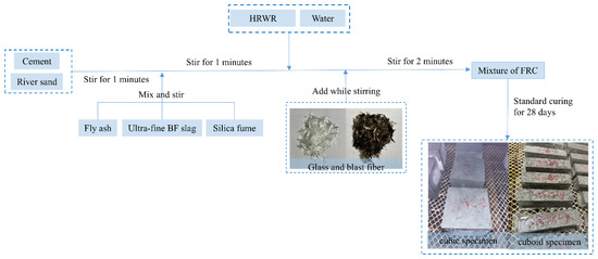
Figure 2.
Mixing procedures of HPC with different fibers.
A total of 81 samples were prepared in this experiment and divided into three groups: A, B, and C. 27 samples in group A were dried in an oven at 105 °C for 24 h, with their mass measured every 4 h. Group B included 24 specimens immersed in water until testing (at least 48 h), with their mass also measured at 4 h intervals. It should be noted that the water on the surface of immersed samples was removed with wet cotton (before the test). The 24 samples in group C were stored at room temperature. Once the mass measurements of Groups A and B stabilized, the specimens were considered to have reached a dry and fully saturated state, respectively. In addition, the water saturation degree of concrete was calculated using Equation (1).
2.3. Testing Methods
2.3.1. Uniaxial Compression Test
According to ASTM C39 [25], uniaxial compression tests were carried out on the specimens using an Instron 1346 microcomputer-controlled electro-hydraulic servo compression testing machine (Instron Corporation, Wycombe, UK) with a load capacity of 2000 kN, as shown in Figure 3. An axial linear variable differential transformer (LVDT) was installed between the loading plates to record the stress–strain data. Vaseline was applied to the top and bottom surfaces of the specimens to reduce the influence of end friction. A spherical seating block, also referred to as an upper bearing block or suspension block, was placed above the specimen to ensure uniform stress distribution on the specimen top.
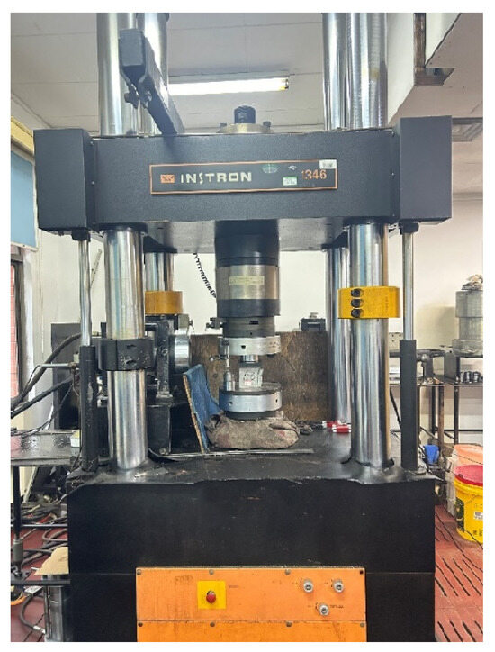
Figure 3.
Uniaxial compression testing machine.
2.3.2. Splitting Tensile Test
27 cubic specimens were subjected to static splitting tests using a Hualong WAW-300 electro-hydraulic servo compression testing machine (Shanghai Hualong Testing Instrument Co., Ltd., Shanghai, China) with a maximum load capacity of 300 kN. Three specimens were tested for each type, and the average value was taken as the final result. According to the specification for splitting tensile strength tests of concrete cubes, cubic specimens with a side length of 150 mm were adopted, with a maximum aggregate size of 40 mm. Steel loading strips and plywood (or hard fiberboard) pads were used. The steel strips had an arc surface with a diameter of 150 mm and a length not shorter than the side length of the specimen. The plywood or hard fiberboard pads were 15–20 mm wide and 3–4 mm thick, and could not be reused.
It is worth noting that the splitting test is a simple and effective method to measure tensile strength; however, stress concentrations often occur at the loading points of the specimen, which may lead to inaccurate results. Wang et al. [26] argued that the test results are valid only when cracks initiate from the specimen center. According to the Chinese “Test Code for Hydraulic Concrete,” the splitting tensile strength of concrete, σt, can be calculated by Equation (2):
where σt—concrete splitting tensile strength (MPa); P—extreme root load (N); A—specimen splitting surface area (mm2).
What also should be noted is that the calculation and elimination of abnormal data for splitting tensile strength follow the same principle as those for compressive strength. When converting the splitting tensile strength obtained by this method to axial tensile strength, a conversion coefficient of 0.9 should be applied. For non-standard specimens with dimensions of 100 mm × 100 mm × 100 mm, a conversion coefficient of 0.85 should be used.
2.3.3. Three-Point Bending Test
Three-point bending tests were conducted on 27 prismatic specimens with dimensions of 40 × 40 × 160 mm3 using a Hualong WAW-300 electro-hydraulic servo testing machine, following the GB/T 17671-1999 standard [27] (Figure 4). Three prismatic specimens were tested for each type, and the average value was taken as the final result. The specimens had a clear span of 100 mm at the bottom. The loading was displacement-controlled at a rate of 0.01 mm/min. The mid-span deflection was measured using an LVDT. The flexural strength fb was calculated according to Equation (3).
where F is the peak load (N), L is the span length (mm), b is the specimen width (mm), and h is the specimen height (mm).
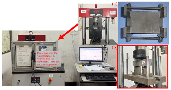
Figure 4.
Test machine and fixture: (a) splitting fixture; (b) bending fixture.
3. Experimental Results
3.1. Failure Mode of Sample
3.1.1. Compressing Failure Mode
As the load increases, the plain concrete (P) produces a large crushing noise. Following the maximum load, the hoop effect causes the surrounding concrete to crush and peel away, forming a pyramid-shaped block, as illustrated in Figure 5.
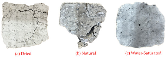
Figure 5.
The compression failure mode diagram of plain concrete under different saturation levels.
For FRC, the crack width gradually increases as the cuttings fall. The cross-sectional area is in the shape of an outer drum. However, the specimens crack but do not break. Their failure is not as sudden and rapid as that of P. The early failure sound is a noisy tearing sound, and the later failure sound is dull (Figure 6).
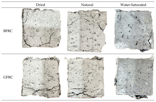
Figure 6.
The compressing failure mode of BFRC and GFRC under different saturation levels.
3.1.2. Tensile Failure Mode
In the initial phase of testing the plain concrete, the load progressively rose as displacement increased. When the deformation approached the limit displacement, the increase in the load value did not change significantly. The specimen rapidly fractured into two parts when a macro crack developed at its center, resulting in a smooth and distinct cross-section (Figure 7).
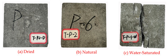
Figure 7.
The tensile failure mode diagram of plain concrete under different saturation levels.
For FRC, the initial load rises linearly with increasing displacement, but as deformation nears the limit displacement, the load growth rate decelerates. The specimen fractures into two distinct sections with a clear yet uneven break when a macro crack develops centrally. Like conventional concrete, FRC exhibits a quieter fracture sound and features numerous tensile fibers on the fracture surface. Due to the low elastic modulus of the fiber, it is unable to effectively support the tensile load, resulting in a load that is nearly zero. The specimen stretches until fracture, where the fibers are observed to be pulled off, demonstrating strong bonding between the fiber and concrete (Figure 8).
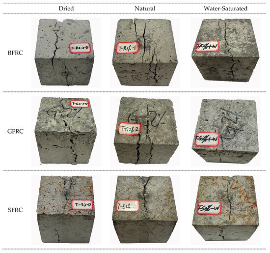
Figure 8.
The tensile failure mode of BFRC and GFRC under different saturation levels.
3.1.3. Bending Failure Mode
During the bending test, plain concrete (P) failed abruptly. As the load increased, the specimen cracked and then quickly broke into two parts. In FRC, a buffer period existed between crack formation and fracture. Despite the brief duration, the findings confirmed an enhancement in concrete toughness. It can be seen from Figure 9 and Figure 10 that the crack propagation path of FRC is tortuous.
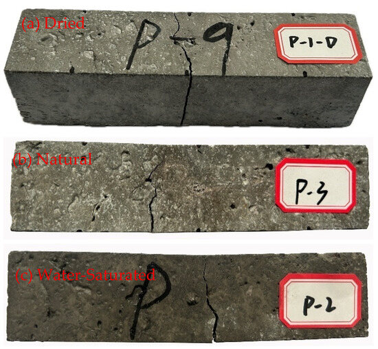
Figure 9.
The bending failure mode diagram of plain concrete under different saturation levels.
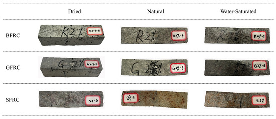
Figure 10.
The bending failure mode of BFRC and GFRC under different saturation levels.
3.2. Mechanical Property
3.2.1. Performance Parameters of Compressing
Through the uniaxial compression test, the mechanical properties of BFRC and GFRC are shown in Table 4 and Figure 11.

Table 4.
Experimental parameters of samples under compression.
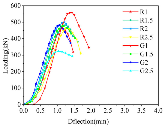
Figure 11.
Compressive Loading-Displacement curve of FRC.
The toughness of concrete refers to its ability to absorb energy and resist fracture failure during loading, which is generally quantified by the area enclosed by the load–displacement curve and the x-axis. In this study, following a combined approach of ASTM C1080 and JSCE-SF4 [28], the ratio of areas is adopted to evaluate the toughness of concrete in both the pre-peak quasi-linear deformation stage and the post-peak failure stage [29].
Specifically, reference displacements are selected as 0.75δc, δc, and 1.35δc, where δc is the peak displacement. Three vertical lines are drawn at these displacements to intersect the load–displacement curve, thereby defining the enclosed areas A1, A2, and A3, as illustrated in Figure 12. Based on these areas, two indices I0 and I1 are introduced to characterize the compressive toughness of concrete, which can be calculated according to Equations (4) and (5).
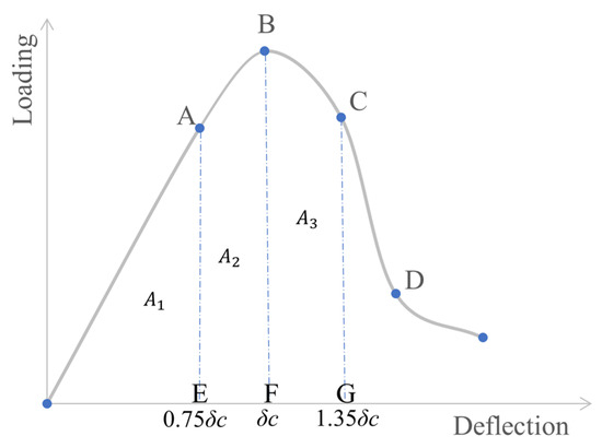
Figure 12.
Advanced evaluation method of toughness.
The calculation results are presented in Table 4. Based on the toughness indices of the two fiber types at different fiber volume fractions, line charts were plotted as shown in Figure 13. It can be clearly observed that both I0 and I1 exhibit a trend of first decreasing and then increasing with the increase in fiber content.
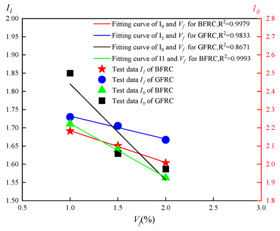
Figure 13.
Fitting curve of fiber volume fraction and toughness index I1 and I0.
As shown in Figure 13, within the fiber volume content range of 1–2%, the relationship between the toughness indices and fiber content can be approximately expressed by linear fitting, which can be formulated as Equations (6) and (7).
Here, I00 and I10 denote the toughness indices of plain concrete without fiber addition. β0 and β1 represent the toughness influence coefficients, which are dependent on the fiber type and casting process. The fitted values obtained from the calculations are βB0 = −0.143, βB1 = 0.367; βG0 = −0.210, βG1 = 0.172.
3.2.2. Performance Parameters of Bending
Through the three-point bending test, the mechanical properties of BFRC and GFRC are shown in Table 5, Figure 14 and Figure 15.

Table 5.
Experimental parameters of bending specimen.
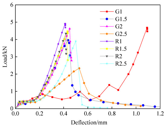
Figure 14.
Bending Load-Deflection curve of FRC.
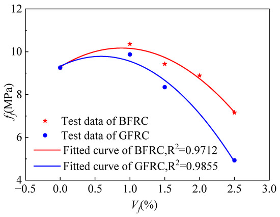
Figure 15.
Fitting curve of fiber volume fraction and flexural strength.
Based on previous research findings [30,31] and considering the distribution of corresponding strength values in Figure 15, the relationship between the flexural strength of fiber-reinforced concrete (FRC) and the fiber volume content can be approximately fitted using a quadratic function, as expressed in the following equation:
Here, ff0 can be regarded as the flexural strength of plain concrete. The calculated coefficients for BFRC and GFRC are λ21 = 0.217, λ22 = −0.123; λ21 = 0.170, λ22 = −0.145, respectively.
The flexural toughness of FRC can be evaluated by the fracture energy (Gf). In this study, the fracture energy was determined by calculating the area enclosed by the load–deflection curve and the x-axis up to 1.2 times the peak deflection δf. The results are shown in Table 5, and the variation in fracture energy with fiber volume content is illustrated in Figure 16. The results indicate that the fracture energy first increases and then decreases with the increase in fiber volume content, reaching its maximum when the fiber content is 1%. By introducing a deflection influence coefficient ηf, the relationship between fiber volume content and fracture energy can be derived, and the final expression is given in Equation (12).
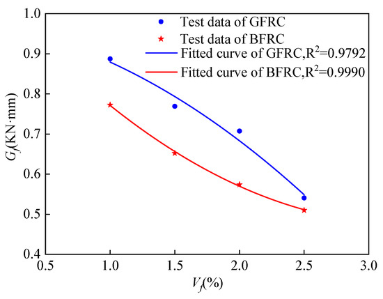
Figure 16.
Fitting curve of fiber volume fraction and fracture energy.
The reduction in splitting energy with increasing fiber content may be attributed to the tendency of fibers to entangle with each other, forming “agglomerates.” Within these agglomerates, the fibers cannot be sufficiently wrapped by the cement paste, leaving residual air or moisture that results in micro-pores. Under splitting load, these pores act as “stress concentration points,” where the main crack preferentially propagates. Since the propagation path requires little energy consumption (without the need to overcome the tensile strength of the matrix), the splitting energy decreases significantly.
According to previous studies, a strong correlation exists between the compressive strength and flexural strength of concrete. For plain concrete of the same strength grade, the flexural-to-compressive strength ratio (flexural–compressive ratio) is approximately constant. However, due to the presence and volume fraction of fibers, this ratio varies in FRC. Therefore, in this study, the flexural–compressive ratio of plain concrete was first calculated, and on this basis, an enhancement coefficient was introduced. Finally, the flexural–compressive ratio equations for BFRC and GFRC were obtained, as expressed in Equations (13) and (14).
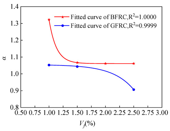
Figure 17.
Fitting curve of fiber volume fraction and enhancement coefficient.
3.2.3. Tensile Performance Parameters
The mechanical property parameters of BFRC and GFRC were obtained by the splitting test, as shown in Table 6, Figure 18 and Figure 19.

Table 6.
Experimental parameters of specimens tensile spitting.
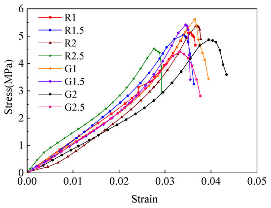
Figure 18.
Tensile stress–strain curve of FRC.
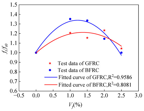
Figure 19.
Fitting curve of fiber volume fraction and tensile strength ratio.
According to Table 6, the fiber volume fraction has a significant effect on the tensile properties of concrete. For GFRC, the tensile strength first increased and then decreased with the increase in glass fiber content. At a fiber volume fraction of 1%, the tensile strength reached the highest improvement, with an increase of 35.09%. At this same dosage, the tensile elastic modulus, ultimate tensile strain, and splitting energy were enhanced by 12.70%, 26.20%, and 53.90%, respectively. For BFRC, the variation trend of tensile strength with fiber content was less obvious. The maximum strength was observed at a fiber content of 2%, but the performance at 1% is particularly noteworthy. Despite being only half the dosage of 2%, the tensile strength at 1% was nearly identical to that at 2%. Specifically, at a fiber content of 1%, the tensile strength, elastic modulus, ultimate tensile strain, and splitting energy increased by 20.87%, 10.36%, 17.05%, and 40.33%, respectively.
Based on the test results, the relationship between the fiber property value and the tensile strength ratio is plotted (Figure 20, Equation (17)).
where ft0 is the tensile strength of plain concrete. λ3 is the tensile strength influence coefficient. As shown in Figure 20, λ31 = 0.312, λ32 = −0.114 for BFRC, and λ31 = 0.542, λ32 = −0.222 for GFRC.
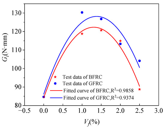
Figure 20.
Relationship between the volume content and fracture energy.
The fracture energy of concrete is an important parameter reflecting the energy dissipation during fracture and crack propagation. It can be observed that the fracture energy of FRC is significantly higher than that of plain concrete, mainly because additional energy is consumed by the fibers during crack bridging and pull-out processes.
In this study, the fracture energy was calculated as the energy required to propagate a unit area of crack surface. Specifically, it is defined as the ratio of the area under the load–crack opening displacement (P–CMOD) curve to the cross-sectional area of the specimen. In other words, the fracture energy corresponds to the integral of the stress–crack width curve normalized by the fracture surface area, as expressed in the following equation:
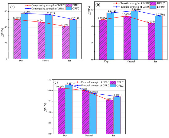
Figure 21.
Mechanical properties of fiber-reinforced concrete under different moisture contents: (a) fc; (b) ft; (c) ff.
It can be seen from Figure 20 that the fracture energy of concrete increases first and then decreases with the increase in volume content. The fitting equation of fiber volume content and fracture energy is:
where µ is the fracture energy influence coefficient, µ = 0.6691.
There are many ways to characterize the fracture properties of concrete. This article uses the characteristic length proposed by Hillerborg to analyze the fracture characteristics of FRC [32]:
The characteristic length parameters of each specimen are listed in Table 6. It is well established that the characteristic length of concrete is negatively correlated with its brittleness. Experimental results indicate that when the fiber volume fraction is 1%, the characteristic length of BFRC and GFRC increases by 7.01% and 3.03%, respectively. In addition, the characteristic lengths of other fiber-reinforced concretes are also significantly higher than that of plain concrete. In other words, the incorporation of basalt fibers and glass fibers leads to an overall increase in the characteristic length of concrete, indicating reduced brittleness and enhanced toughness.
Therefore, based on the mechanical performance of FRC with different fiber types, and considering engineering economy and practical feasibility, the optimal dosage of both basalt fiber and glass fiber is determined to be 1%.
3.3. Comparison of Concrete Properties at Different Moisture Contents
As shown in Figure 21, the compressive strength of BFRC in the dry state and saturated state is 107.06% and 88.66% of that in the natural state, respectively; the flexural strength is 106.20% and 78.02% of that in the natural state. The compressive strength of GFRC in the dry state and saturated state is 106.64% and 88.88% of that in the natural state, respectively; the flexural strength is 121.55% and 92.26% of that in the natural state. That is the flexural and compressive strengths of the two types of fiber concrete decrease with the increase in moisture content, which is similar to the law of general concrete. In terms of splitting strength, the strengths of the two types of fiber concrete are lower than those in the natural state, which are 91.15% and 95.74% of those in the natural state, respectively. The reason for this phenomenon may be that during the drying process of the sample, the temperature rises, causing the concrete volume to expand and the development of cracks inside the concrete. In addition, it is not difficult to see that the moisture content has little effect on the compressive and splitting strength of the two fiber concretes, but has a significant effect on the flexural strength. That is, under the same fiber content, GFRC has a greater strength increase in the dry state and a smaller strength loss in the saturated state than BFRC.
As shown in Figure 22, the compressive toughness of both basalt fiber and glass fiber-reinforced concrete exhibits an initial increase followed by a decrease as saturation increases. However, it is evident that under saturated conditions, the decline in the I1 value of fiber-reinforced concrete is significantly smaller than that in the I0 value, indicating that changes in saturation have a lesser impact on I1. Based on the definitions of these indices, it can be inferred that the water content has a greater influence on the non-elastic deformation of fiber-reinforced concrete before failure. Furthermore, the presence of fibers effectively enhances the toughness of the concrete beyond its peak strength.
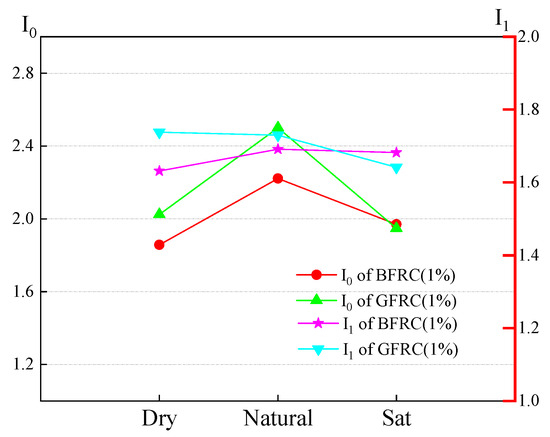
Figure 22.
Toughness indexes of fiber-reinforced concrete under different saturation.
Figure 23 shows the fitting curves of the fracture energy of BFRC and GFRC calculated according to Equation (18) under different moisture contents. As shown in Figure 23, under saturated conditions, the fitting result of BFRC is much better than that of GFRC, and from the coefficient of variation in the fitting curves on both sides, the fitting effect of BFRC is better than that of GFRC, indicating that glass fiber is more sensitive to moisture content than basalt fiber. The possible reason is that glass fiber has weak alkali resistance, while concrete is alkaline under saturation conditions.
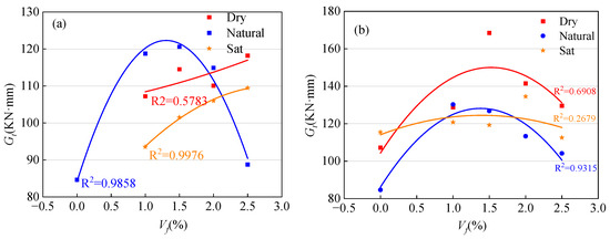
Figure 23.
Fitting curve of fracture energy of fiber-reinforced concrete under different saturation levels: (a) BFRC, (b) GFRC.
As shown in Figure 24, compared to the natural state, the flexural fracture energy of basalt fiber-reinforced concrete (BFRC) decreased by 25.16% and 32.80% under dry and saturated conditions, respectively. Similarly, the corresponding values for glass fiber-reinforced concrete (GFRC) were 21.40% and 41.49%. This indicates that at higher moisture content, the flexural brittleness of fiber-reinforced concrete significantly increases. This may be attributed to the excessive free water, which reduces the strength of the cement and other binding materials.
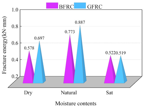
Figure 24.
Flexural fracture energy of fiber-reinforced concrete under different water conditions.
In summary, similar to ordinary concrete, the strength and toughness of fiber-reinforced concrete generally exhibit a trend of increasing first and then decreasing with the rise in moisture content. The reasons for this behavior may be as follows:
- (1)
- Pore Formation and Internal Stress: As moisture content increases, excess water occupies the internal spaces of concrete, creating micro-pores and voids. These weaken the internal structure, reducing the concrete’s density and strength. Additionally, water within the concrete is prone to expansion and shrinkage, leading to volume changes. These changes generate internal stresses that further reduce the strength of the concrete.
- (2)
- Weakened Aggregate-Cement Bonding: Higher moisture content decreases the bonding strength between aggregates and cement, adversely affecting the overall integrity of the concrete.
- (3)
- Carbonation Effect: Concrete interacts with CO2 in the air, leading to surface corrosion and carbonation. As the extent of corrosion deepens, it spreads to the interior of the concrete. The carbonation effect intensifies with increasing moisture content, further compromising the concrete’s strength.
- (4)
- Impact of Low Moisture Content: Insufficient moisture can negatively affect the bonding between fibers and concrete as well as between aggregates and the cement matrix, reducing the adhesive strength.
For the FRC studied in this research, the addition of fibers effectively improves the internal structure of the concrete. The fibers play a positive role in preventing crack propagation, mitigating the carbonation effect, and enhancing the bonding between aggregates and the cement mortar. These improvements reduce the adverse effects of moisture content on concrete strength. In practical engineering applications, the moisture content in concrete should be controlled within an appropriate range to ensure stable quality and performance.
4. Discussion
4.1. Effect of Fiber on Mechanical Properties
The reliability of the interfacial bond between concrete and fibers plays a critical role in the reinforcement effect. A comparison of Figure 7 and Figure 8 shows that, upon failure, the crack development in fiber-reinforced concrete is significantly improved compared to plain concrete, indicating that the presence of fibers substantially enhances the overall ductility and toughness of the material under fracture.
Furthermore, analysis of Table 4, Table 5 and Table 6 reveals that the strengthening effect of fibers in compression is notably weaker than that in splitting tensile and flexural performance. For example, specimen G1 exhibited only a 1.3% increase in compressive strength compared with plain concrete, while the improvements in tensile and flexural strength were 6.6% and 35.1%, respectively. This is because, under compressive loading, fibers primarily resist stress along the direction of the external load. Given the brittle and rigid nature of fibers, their resistance to compression is limited. Although fibers can inhibit lateral tensile cracks in different directions, thereby dissipating part of the energy and enhancing the compressive strength and toughness of concrete, their reinforcement effect under compression is relatively weaker than under tension or bending.
The reinforcing role of fibers is achieved by improving internal structural defects, restraining crack propagation, and coordinating stress distribution. However, all of these depend on the bond performance between fibers and the concrete matrix [33,34,35]. Microscopic observations further demonstrate the bonding effectiveness of the two types of fibers with the cementitious matrix (Figure 25). It can be seen that basalt fibers exhibit a tighter bond with the matrix compared with glass fibers.
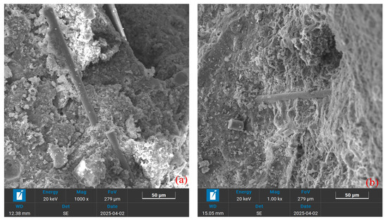
Figure 25.
SEM Images of Fibers: (a) glass fiber; (b) basalt fiber.
It should also be noted that in this study, regardless of strength, toughness, or energy dissipation capacity, the mechanical performance parameters generally showed a trend of increasing first and then decreasing with fiber volume content. According to existing theoretical studies, when the fiber content is relatively low, the crack propagation rate in fiber-reinforced concrete can be effectively restrained. In contrast, when the fiber content is excessive, the high fiber volume and poor dispersion lead to agglomeration or void formation, significantly weakening the bond between fibers and the matrix, and ultimately diminishing the reinforcement effect.
4.2. Effect of Fly Ash and Ultrafine Slag
Fly ash is a pozzolanic material rich in fine particles, mainly composed of silicates and aluminates, while ultrafine slag refers to ground slag with particle sizes smaller than 10 μm, which serves as a novel mineral admixture for concrete. Their strengthening mechanisms in concrete can be summarized as follows:
The particle morphology, internal and external structure, density, and particle size distribution of these materials alter the workability of concrete mixtures. The spherical glass microspheres in fly ash enable uniform particle dispersion within the paste, reduce interparticle friction, enhance the fluidity of the mixture, and improve water-reducing effects, thereby producing a more uniform and compact mix. Ultrafine slag, characterized by smooth surfaces and stable properties, consists of fine spherical particles that act like micro-ball bearings in concrete, reducing frictional resistance and effectively improving the workability of fresh concrete (including flowability, cohesiveness, and water retention). A microscopic view of their morphology is shown in Figure 26.
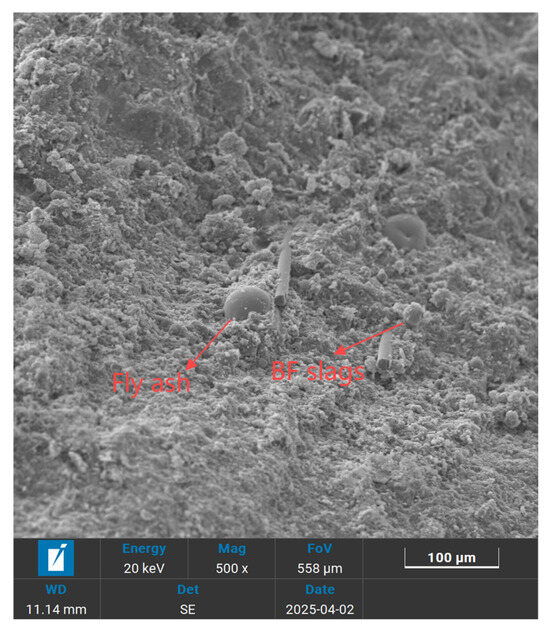
Figure 26.
SEM Images of Fly ash and Ultrafine slags.
Both fine particles are uniformly distributed within the concrete matrix, thereby enhancing the structural rigidity of the hardened paste. The specific advantages include the following: fly ash in the concrete paste reduces capillary porosity and improves the strength of fly ash concrete; the solid, thick-walled hollow glass microspheres in fly ash exhibit high strength, which can further reinforce the cement paste. Moreover, as these microspheres are dispersed throughout the hardened cement paste, the longer the curing time, the stronger their bonding with the cementitious matrix. At the interface between fly ash and cement paste, the hardness of the hydration gel formed by fly ash is higher than that of the cement hydration gel [36].
In addition, incorporating these admixtures can reduce cement consumption and hydration heat, while improving the impermeability, frost resistance, crack resistance, and corrosion resistance of concrete, thus extending the service life of concrete structures [37,38,39]. In practical applications, either fly ash or ultrafine slag can be used alone, or they can be combined, depending on specific engineering requirements and material properties, to achieve optimal performance.
4.3. Effect of Two Types of Fibers
In general, fibers differ in terms of material properties and functionality. For example, fibers such as SF (steel fiber), CF (carbon fiber), BF (basalt fiber), and GF (glass fiber) are well-known for their high tensile strength and elastic modulus. These fibers are capable of enhancing the stiffness and tensile strength of concrete. On the other hand, fibers like PPF (polypropylene fibers), polyethylene fibers, and nylon fibers have low tensile strength and elastic modulus. However, their incorporation helps improve the concrete’s resistance to shrinkage cracking and may promote ductile failure in concrete.
Overall, the material properties and functional contributions of different fibers in concrete vary significantly. For instance, steel fibers (SF), carbon fibers (CF), basalt fibers (BF), and glass fibers (GF) are characterized by high tensile strength and high elastic modulus, thereby improving the stiffness and tensile strength of concrete [40,41,42]. In contrast, polypropylene fibers (PPF), polyethylene fibers, and nylon fibers exhibit lower tensile strength and elastic modulus; however, their inclusion is beneficial for enhancing the resistance of concrete to shrinkage cracking and may also promote a ductile failure mode [43,44,45].
Glass fiber is a high-performance inorganic nonmetallic material available in various forms, featuring excellent insulation, heat resistance, corrosion resistance, and mechanical strength. However, its large brittleness and low wear resistance limit its broader use [ref]. Basalt fiber, on the other hand, is a novel, eco-friendly inorganic high-performance material with superior tensile strength, outstanding corrosion resistance, electrical insulation, and thermal stability. Its production generates minimal waste and pollution, and the fiber itself is biodegradable and harmless after disposal, making it a truly sustainable material.
Similarly to steel reinforcement, both GF and BF can enhance the tensile, flexural, and compressive strengths of concrete [38,46]. Nevertheless, their service temperature ranges differ significantly: basalt fiber typically operates between −269 °C and 700 °C, while glass fiber is suitable for −60 °C to 450 °C. Moreover, basalt fiber retains 80% of its initial tensile strength even after fracture at 600 °C [ref]. Its chemical composition, which includes K2O, MgO, and TiO2, contributes to excellent chemical stability, corrosion resistance, and waterproofing capacity, thereby outperforming GF in terms of alkali resistance and long-term durability. In contrast, the primary advantage of GF lies in its ability to resist crack initiation and propagation, thus improving the toughness and impact resistance of concrete.
From the perspective of toughness (Table 4), at the same fiber content, concretes incorporating GF exhibit higher values of both I0 and I1 compared to those with BF, with the largest differences (0.20 and 0.31, respectively) observed at a fiber dosage of 2.5%. Similarly, based on the energy absorption capacity at failure (Table 5 and Table 6), both Gt and Gf values for GFRC exceed those of BFRC, with maximum advantages of 23.4% and 17.3%, respectively.
However, when specimens are fully saturated, the results reveal distinct differences. As shown in Figure 24, compared with the natural moisture condition, the flexural fracture energy of BFRC decreases by 32.80% under saturated conditions, whereas that of GFRC decreases by 41.49%. Furthermore, the fitted equations in Figure 23 indicate that, in the saturated state, GFRC achieves a coefficient of determination (R2) of only 0.2679, in contrast to 0.9976 for BFRC, demonstrating that GF is more sensitive to moisture, and its strength–fiber content relationship established under natural conditions requires considerable adjustment.
4.4. Effect of Water Saturated Level
Similarly to ordinary concrete, the strength of fiber-reinforced concrete (FRC) in this study decreases with increasing moisture content, following the order: dry state > natural state > saturated state. However, a distinct phenomenon was observed regarding compressive toughness and the energy absorbed during flexural failure: both parameters exhibited a trend of first increasing and then decreasing with moisture content, reaching their maximum values in the natural state.
This behavior may be explained as follows. At low moisture levels, the presence of water can promote mild secondary hydration of unhydrated cement particles, generating additional C–S–H gel that fills interfacial voids and enhances the mechanical interlock between fibers and the matrix. Furthermore, water infiltration into gel pores and capillary pores of the cement paste provides a lubricating effect, reducing sliding resistance among hydration products (e.g., C–S–H particles). This imparts a certain degree of plasticity to the matrix, mitigating sudden brittle fracture and offering fibers more time to exert their crack-bridging effect.
In contrast, when the moisture content becomes excessively high, pores within the concrete are completely filled with water. Under applied loading (particularly compressive and flexural loads), the entrapped water cannot be expelled promptly, thereby generating pore water pressure. This internal pressure offsets part of the load-bearing capacity of the matrix, causing macro-cracks to appear at lower external loads.
Additionally, the intrinsic properties of fibers are also influenced by moisture. Glass fibers, for example, are more prone to degradation under higher moisture conditions due to the alkaline environment of concrete; increased water content intensifies the likelihood of alkali-induced corrosion, thereby accelerating the performance deterioration of glass fibers compared to basalt fibers.
From an engineering perspective, it is therefore essential to maintain the moisture content of concrete within a reasonable range to ensure stable quality and reliable performance of fiber-reinforced systems.
5. Conclusions
To investigate the impact of fiber type, fiber content, and water content on the static mechanical characteristics of contemporary HPC materials, a series of static compression, splitting, and three-point bending tests was conducted. The study examined the static mechanical properties of high-performance concrete and explored how fiber type, fiber content, and water saturation affect these properties. The conclusions are as follows:
- (1)
- The failure modes of HPC materials under different loading conditions were analyzed. Under compression, for FRC specimens, the crack width gradually increased with the falling of rock chips, and the cross-sectional area was bulging. Their failure was not sudden like that of plain concrete. Under tension, the fracture of FRC specimens was similar to that of ordinary concrete, with a small fracture sound and a large number of tensile fibers on the fracture surface. Compared with glass fiber, basalt fiber has better bonding performance with concrete. Under bending, fiber-reinforced concrete (FRC) exhibits a delay between crack initiation and fracture compared to plain concrete, with a more tortuous crack propagation path.
- (2)
- The optimal fiber volume fraction was identified as 1%, at which FRC exhibited the best performance. Relationships between fiber volume fraction, flexural strength, and fracture energy were established. The fitting equations yielded good results under natural moisture conditions but were less satisfactory under dry and saturated conditions.
- (3)
- Both fibers improved the compressive, tensile, and flexural strengths of concrete. Under natural conditions, glass fibers were more effective in enhancing toughness and energy absorption than basalt fibers, whereas basalt fibers demonstrated greater stability than glass fibers in saturated conditions.
- (4)
- Similarly to ordinary concrete, the overall mechanical strength of FRC decreased with increasing saturation. However, toughness and energy absorption first increased and then decreased, reaching their peak values in the natural state. This trend was attributed not only to the effect of moisture on the concrete matrix but also to the influence of water on fiber properties.
Author Contributions
S.B.: Methodology, Data curation, Validation, Writing—review & editing. S.W. (Shuangjie Wang): Conceptualization, Supervision, Writing—original draft. S.W. (Sheng Wang): Validation, Visualization, Formal analysis. X.T.: Software, Writing—review & editing. T.G.: Formal analysis, Writing—review & editing. All authors have read and agreed to the published version of the manuscript.
Funding
This research received no external funding.
Data Availability Statement
All data, models, and code generated or used during the study are available from the corresponding author upon reasonable request.
Conflicts of Interest
Author Sheng Wang was employed by the company China Communications Construction Co., Ltd. The remaining authors declare that the research was conducted in the absence of any commercial or financial relationships that could be construed as a potential conflict of interest.
References
- Parvez, A.; Foster, S.J. Fatigue of steel-fibre-reinforced concrete prestressed railway sleepers. Eng. Struct. 2017, 141, 241–250. [Google Scholar] [CrossRef]
- Khalel, H.; Khan, M.; Starr, A.; Khan, K.A.; Muhammad, A. Performance of engineered fibre reinforced concrete (EFRC) under different load regimes: A review. Constr. Build. Mater. 2021, 306, 124692. [Google Scholar] [CrossRef]
- Niu, F.; Liu, Y.; Xue, F.; Sun, H.; Liu, T.; He, H.; Liao, H. Ultra-high performance concrete: A review of its material properties and usage in shield tunnel segment. Case Stud. Constr. Mater. 2025, 22, e04194. [Google Scholar] [CrossRef]
- Ali, B.; Raza, S.S.; Kurda, R.; Alyousef, R. Synergistic effects of fly ash and hooked steel fibers on strength and durability properties of high strength recycled aggregate concrete. Resour. Conserv. Recycl. 2021, 168, 105444. [Google Scholar] [CrossRef]
- Yang, W.; Tang, Z.; Wu, W.; Zhang, K.; Yuan, J.; Li, H.; Feng, Z. Effect of different fibers on impermeability of steam cured recycled concrete. Constr. Build. Mater. 2022, 328, 127063. [Google Scholar] [CrossRef]
- Devi, C.; Vijayan, D.S.; Nagalingam, R.; Arvindan, S. A review of the implementations of glass fiber in concrete technology. Mater. Today Proc. 2022, 62, 2010–2015. [Google Scholar] [CrossRef]
- Wei, J.; Meyer, C. Utilization of rice husk ash in green natural fiber-reinforced cement composites: Mitigating degradation of sisal fiber. Cem. Concr. Res. 2016, 81, 94–111. [Google Scholar] [CrossRef]
- Ahmad, J.; González-Lezcano, R.A.; Majdi, A.; Ben Kahla, N.; Deifalla, A.F.; El-Shorbagy, M.A. Glass Fibers Reinforced Concrete: Overview on Mechanical, Durability and Microstructure Analysis. Materials 2022, 15, 5111. [Google Scholar] [CrossRef]
- Ali, B.; Qureshi, L.A. Influence of glass fibers on mechanical and durability performance of concrete with recycled aggregates. Constr. Build. Mater. 2019, 228, 116783. [Google Scholar] [CrossRef]
- Zhou, J.; Wang, G.; Zhu, G. The durability of basalt-fiber-reinforced cement mortar under exposure to unilateral salt freezing cycles. Front. Mater. 2023, 10, 1202889. [Google Scholar] [CrossRef]
- Wang, Y.; Kang, A.-H.; Wu, Z.-G.; Xiao, P.; Gong, Y.-F.; Sun, H.-F. Investigation of the basalt fiber type and content on performances of cement mortar and concrete. Constr. Build. Mater. 2023, 408, 133720. [Google Scholar] [CrossRef]
- Bencardino, F.; Mazzuca, P.; Carmo, R.D.; Costa, H.; Curto, R. Cement-Based Mortars with Waste Paper Sludge-Derived Cellulose Fibers for Building Applications. Fibers 2024, 12, 13. [Google Scholar] [CrossRef]
- Jin, L.; Du, X.; Ma, G. Macroscopic effective moduli and tensile strength of saturated concrete. Cem. Concr. Res. 2012, 42, 1590–1600. [Google Scholar] [CrossRef]
- Isa, M.N.; Pilakoutas, K.; Guadagnini, M. Determination of tensile characteristics and design of eco-efficient UHPC. Structures 2021, 32, 2174–2194. [Google Scholar] [CrossRef]
- Chen, M.; Zhong, H.; Wang, H.; Zhang, M. Behaviour of recycled tyre polymer fibre reinforced concrete under dynamic splitting tension. Cem. Concr. Compos. 2020, 114, 103764. [Google Scholar] [CrossRef]
- Jiang, J.; Feng, T.; Chu, H.; Wu, Y.; Wang, F.; Zhou, W.; Wang, Z. Quasi-static and dynamic mechanical properties of eco-friendly ultra-high-performance concrete containing aeolian sand. Cem. Concr. Compos. 2019, 97, 369–378. [Google Scholar] [CrossRef]
- GB/T 1596-2017; Fly Ash Used for Cement and Concrete. Standardization Administration of the People’s Republic of China, SAC: Beijing, China, 2019.
- Su, Y.; Li, J.; Wu, C.; Wu, P.; Tao, M.; Li, X. Mesoscale study of steel fibre-reinforced ultra-high performance concrete under static and dynamic loads. Mater. Des. 2017, 116, 340–351. [Google Scholar] [CrossRef]
- Habel, K.; Gauvreau, P. Response of ultra-high performance fiber reinforced concrete (UHPFRC) to impact and static loading. Cem. Concr. Compos. 2008, 30, 938–946. [Google Scholar] [CrossRef]
- Farnam, Y.; Mohammadi, S.; Shekarchi, M. Experimental and numerical investigations of low velocity impact behavior of high-performance fiber-reinforced cement based composite. Int. J. Impact Eng. 2010, 37, 220–229. [Google Scholar] [CrossRef]
- Drdlová, M.; Čechmánek, R. Comparison of tensile behaviour of polypropylene, aramid and carbon fibre reinforced cementitious composite at high strain rate loading. Procedia Struct. Integr. 2018, 13, 1731–1738. [Google Scholar] [CrossRef]
- Bahedh, M.A.; Jaafar, M.S. Ultra high-performance concrete utilizing fly ash as cement replacement under autoclaving technique. Case Stud. Constr. Mater. 2018, 9, e00202. [Google Scholar] [CrossRef]
- Hao, Y.; Hao, H. Dynamic compressive behaviour of spiral steel fibre reinforced concrete in split Hopkinson pressure bar tests. Constr. Build. Mater. 2013, 48, 521–532. [Google Scholar] [CrossRef]
- ASTM C192/C192M-24; Standard Practice for Making and Curing Concrete Test Specimens in the Laboratory. ASTM International: West Conshohocken, PA, USA, 2024.
- ASTM-C39/C39M-21; Standard test method for Compressive Strength of Cylindrical Concrete Specimens. ASTM International: West Conshohocken, PA, USA, 2021.
- Wang, Q.-Z.; Xing, L. Determination of fracture toughness KIC by using the flattened Brazilian disk specimen for rocks. Eng. Fract. Mech. 1999, 64, 193–201. [Google Scholar] [CrossRef]
- GB/T 17671-1999; Method of Testing Cements—Determinationof Strength. National Standardization Administration: Beijing, China, 1999.
- JSCE-SF4; Method of Test for Flexural Strength and Flexural Toughness of Fiber Reinforced. Japan Society of Civil Engineers, JSCE: Tokyo, Japan.
- Zhou, H.; Jia, B.; Huang, H.; Mou, Y. Experimental Study on Basic Mechanical Properties of Basalt Fiber Reinforced Concrete. Materials 2020, 13, 1362. [Google Scholar] [CrossRef] [PubMed]
- Jiang, C.; Fan, K.; Wu, F.; Chen, D. Experimental study on the mechanical properties and microstructure of chopped basalt fibre reinforced concrete. Mater. Des. 2014, 58, 187–193. [Google Scholar] [CrossRef]
- Sun, X.; Gao, Z.; Cao, P.; Zhou, C.; Ling, Y.; Wang, X.; Zhao, Y.; Diao, M. Fracture performance and numerical simulation of basalt fiber concrete using three-point bending test on notched beam. Constr. Build. Mater. 2019, 225, 788–800. [Google Scholar] [CrossRef]
- Hillerborg, A.; Modéer, M.; Petersson, P.E. Analysis of crack formation and crack growth in concrete by means of fracture mechanics and finite elements. Cem. Concr. Res. 1976, 6, 773–781. [Google Scholar] [CrossRef]
- Deng, Q.; Zhang, R.; Liu, C.; Duan, Z.; Xiao, J. Influence of fiber properties on abrasion resistance of recycled aggregate concrete: Length, volume fraction, and types of fibers. Constr. Build. Mater. 2023, 362, 129750. [Google Scholar] [CrossRef]
- Banthia, N.; Majdzadeh, F.; Wu, J.; Bindiganavile, V. Fiber synergy in Hybrid Fiber Reinforced Concrete (HyFRC) in flexure and direct shear. Cem. Concr. Compos. 2014, 48, 91–97. [Google Scholar] [CrossRef]
- Ahmed, W.; Lim, C.W. Multicriteria performance assessment of sustainable recycled concrete produced via hybrid usage of basalt, polypropylene and glass fiber. Constr. Build. Mater. 2023, 397, 132462. [Google Scholar] [CrossRef]
- Xi, Y.; Siemer, D.D.; Scheetz, B.E. Strength development, hydration reaction and pore structure of autoclaved slag cement with added silica fume. Cem. Concr. Res. 1997, 27, 75–82. [Google Scholar] [CrossRef]
- Abdulkareem, O.M.; Fraj, A.B.; Bouasker, M.; Khouchaf, L.; Khelidj, A. Microstructural investigation of slag-blended UHPC: The effects of slag content and chemical/thermal activation. Constr. Build. Mater. 2021, 292, 123455. [Google Scholar] [CrossRef]
- Jing, R.; Liu, Y.; Yan, P. Uncovering the effect of fly ash cenospheres on the macroscopic properties and microstructure of ultra high-performance concrete (UHPC). Constr. Build. Mater. 2021, 286, 122977. [Google Scholar] [CrossRef]
- Yang, R.; Yu, R.; Shui, Z.; Gao, X.; Xiao, X.; Zhang, X.; Wang, Y.; He, Y. Low carbon design of an Ultra-High Performance Concrete (UHPC) incorporating phosphorous slag. J. Clean. Prod. 2019, 240, 118157. [Google Scholar] [CrossRef]
- Ashraf, M.J.; Idrees, M.; Akbar, A. Performance of silica fume slurry treated recycled aggregate concrete reinforced with carbon fibers. J. Build. Eng. 2023, 66, 105892. [Google Scholar] [CrossRef]
- Kazmi, S.M.S.; Munir, M.J.; Wu, Y.-F.; Patnaikuni, I.; Zhou, Y.; Xing, F. Axial stress-strain behavior of macro-synthetic fiber reinforced recycled aggregate concrete. Cem. Concr. Compos. 2019, 97, 341–356. [Google Scholar] [CrossRef]
- Ahmed, W.; Lim, C.W. Production of sustainable and structural fiber reinforced recycled aggregate concrete with improved fracture properties: A review. J. Clean. Prod. 2021, 279, 123832. [Google Scholar] [CrossRef]
- Lei, B.; Li, W.; Liu, H.; Tang, Z.; Tam, V.W.Y. Synergistic Effects of Polypropylene and Glass Fiber on Mechanical Properties and Durability of Recycled Aggregate Concrete. Int. J. Concr. Struct. Mater. 2020, 14, 37. [Google Scholar] [CrossRef]
- Afroughsabet, V.; Biolzi, L.; Monteiro, P.J.M. The effect of steel and polypropylene fibers on the chloride diffusivity and drying shrinkage of high-strength concrete. Compos. Part B 2018, 139, 84–96. [Google Scholar] [CrossRef]
- Ahmed, W.; Lim, C.W.; Akbar, A. Influence of Elevated Temperatures on the Mechanical Performance of Sustainable-Fiber-Reinforced Recycled Aggregate Concrete: A Review. Buildings 2022, 12, 487. [Google Scholar] [CrossRef]
- Ahmed, W.; Lim, C.W. Effective recycling of disposable medical face masks for sustainable green concrete via a new fiber hybridization technique. Constr. Build. Mater. 2022, 344, 128245. [Google Scholar] [CrossRef]
Disclaimer/Publisher’s Note: The statements, opinions and data contained in all publications are solely those of the individual author(s) and contributor(s) and not of MDPI and/or the editor(s). MDPI and/or the editor(s) disclaim responsibility for any injury to people or property resulting from any ideas, methods, instructions or products referred to in the content. |
© 2025 by the authors. Licensee MDPI, Basel, Switzerland. This article is an open access article distributed under the terms and conditions of the Creative Commons Attribution (CC BY) license (https://creativecommons.org/licenses/by/4.0/).