Article

Study on the Compression Performance of Prefabricated Reinforced Welded Hollow Sphere Joints

1
State Key Laboratory of Water Engineering Ecology and Environment in Arid Area, Xi’an University of Technology, No. 5 Jinhua Road, Xi’an 710048, China
2
School of Civil Engineering and Architecture, Xi’an University of Technology, No. 5 Jinhua Road, Xi’an 710048, China
3
China Railway First Survey and Design Institute Group Ltd., Xi’an 710043, China
*
Author to whom correspondence should be addressed.
Buildings 2026, 16(7), 1364; https://doi.org/10.3390/buildings16071364
Submission received: 26 February 2026 / Revised: 24 March 2026 / Accepted: 26 March 2026 / Published: 30 March 2026
(This article belongs to the Special Issue Advanced Studies in Structure Materials—2nd Edition)

Abstract

To address the challenges encountered during the in situ welding reinforcement process of hollow spherical joints, including complex construction, limited quality control, and low efficiency, this study proposed a prefabricated reinforced hollow spherical joint. A three-dimensional finite element (FE) model was developed and validated against experimental results to quantify the effects of T-rib web width (b), web thickness (t1), ferrule thickness (t2), hollow-sphere diameter (D), and bolt pretension (fv) on the bearing capacity of the prefabricated joint. Based on these analyses, a predictive model was established for the axial compressive bearing capacity of the prefabricated joint. The results showed that, under compression, the reinforcing components primarily provided a supporting role to the hollow sphere, thereby improving the buckling resistance of the prefabricated joint under compression. The reinforcement mechanism primarily relied on friction between the ferrule and the steel stub for load transfer, with the available frictional resistance governed primarily by bolt pretension and the stiffness of the reinforcing components. When sufficient friction existed between the ferrule and the steel tube, increasing the T-rib web width from 0 mm to 80 mm improved the bearing capacity of the prefabricated joint by 33%. At a T-rib flange height (h)-to-web width ratio of h/b = 1.0, the T-rib satisfied the reinforcement requirement through its inherent strength and stiffness. As the hollow-sphere diameter-to-thickness ratio decreased, the incremental gain in bearing capacity diminished. A predictive model was proposed for compressive bearing capacity by accounting for the support provided by the reinforcing components and the effects of hollow-sphere diameter, steel-tube diameter, and the tube-to-sphere diameter ratio. The proposed model predicted the FE results with errors within ±10%, and the findings can provide a practical reference for designing the compressive bearing capacity of prefabricated reinforced hollow spherical joints.

1. Introduction

1.1. Background, Motivation, and Objective

Welded hollow spherical joints are widely used in large-span spatial grid structures because of their simple configuration and clear load-transfer path. As the primary load-transferring components in spatial grid systems, their mechanical performance directly determines the safety of the structure. During long-term service, welded hollow spherical joints are susceptible to environmental degradation and loading variations; Therefore, safety assessment and reinforcement strategies require urgent attention. In recent years, researchers have conducted systematic experimental, numerical, and theoretical investigations on the mechanical behavior, failure mechanisms, and design methods of welded hollow spherical joints, thereby providing essential support for the safe application of hollow spherical joints. For example, Zhang et al. [1] introduced a novel welded hollow spherical bolted joint for fully assembled large-span spatial steel structures, enhancing construction speed and decreasing energy consumption during manufacturing. Wen et al. [2] conducted a systematic study on the mechanical properties of H-beam welded hollow spherical joints under axial tension, axial compression, and eccentric compression, and they proposed a practical calculation model. Xing et al. [3] conducted uniaxial compression tests on full-scale specimens and demonstrated that the compressive failure of high-strength steel joints was governed by elastic–plastic buckling. Shu et al. [4] proposed a simplified analytical model to clarify the stress distribution in welded hollow spherical joints with triangular ribs. They derived an analytical solution for the yield strength of these joints based on the theory of elastic shells. Shu et al. [5] conducted axial compression tests on four full-size hollow spherical joints. Based on the results from these tests and FE simulations, they proposed a formula for calculating the bearing capacity of welded hollow spherical joints with stiffeners. Chen et al. [6] studied the mechanical properties and failure mechanisms of single-plate welded hollow spherical joints with varying parameters under axial tension. Collectively, these studies have systematically clarified the failure mechanisms of welded hollow spherical joints under various conditions, established evaluation and design approaches for bearing capacity of the joints, and provided a theoretical basis for mechanical performance assessment and the safe service of spatial grid structures.
As building functions are enhanced and service environments grow more complex, critical joints in existing structures often need reinforcement to improve their reliability and durability for safe operation. Therefore, identifying the dominant factors governing the mechanical performance of reinforced hollow spherical joints and, on this basis, proposing effective reinforcement schemes has become an urgent scientific issue. Liu et al. [7] investigated the tensile strength of CFRP-reinforced welded hollow spherical joints and found that tensile strength increased markedly with the number of CFRP layers. Zhao et al. [8] studied the bearing capacity of welded hollow spherical joints reinforced with conical components and proposed an artificial-neural-network-based predictive model for compressive bearing capacity. Tian et al. [9] examined the progressive-collapse resistance of joints reinforced with internal ferrules and found that internal ferrules significantly improved the bearing capacity and deformation capacity of conventional joints, with the maximum increase reaching 60.4%. Zhao et al. [10] compared reinforcement schemes using stochastic FE analysis and found that the proposed conical-component scheme performed better, achieving an increase in compressive bearing capacity approximately 2.5 times that of the hemispherical scheme. Guo et al. [11] investigated joints reinforced with unilateral annular ribs and found that annular ribs increased compressive resistance by 76% relative to unreinforced joints, while the ductility coefficient increased from 1.37 to 1.79. Xu et al. [12] conducted axial compression tests on joints with external stiffeners and found that the number, thickness, and height of stiffeners were positively and linearly correlated with joint compressive resistance. Qiu et al. [13,14] employed the element birth–death method to examine the effects of envelope ratio and sphere-diameter ratio on the mechanical performance of welded hollow spherical joints. These studies collectively clarify how various reinforcement schemes improve the bearing performance of welded hollow spherical joints. They have established calculation models for both bearing capacity and stiffness, providing a reliable support for the design and evaluation of reinforcement joints.
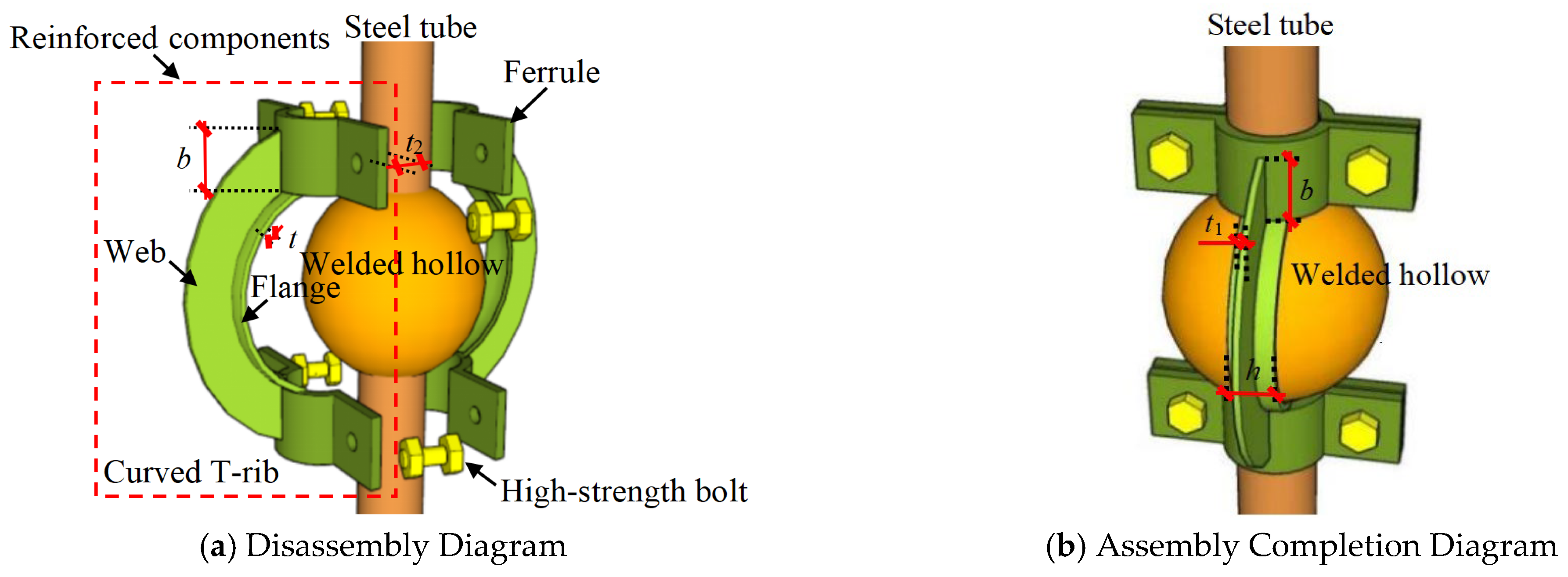
However, spatial grid structures have large spans, with structural heights exceeding 100 m. When reinforcing welded spherical joints, traditional approaches such as circumferential external welding are commonly adopted; Nevertheless, they often entail difficult high-altitude welding operations [15,16], challenges in quality control [17,18,19,20], and low construction efficiency [21,22,23]. To address these limitations, our research group [24] proposed a novel prefabricated reinforcement scheme. As shown in Figure 1, the reinforcing component was fabricated in the factory by welding the annular T-rib flange and web to the ferrule (Figure 1a). On site, reinforcing components on both sides of the welded hollow sphere were connected to the steel tubes using high-strength bolts. The frictional resistance generated by contact pressure between the ferrule and the steel tubes was then mobilized to enhance tensile, compressive stiffness, and bearing capacity of the spherical joint (Figure 1b). During factory fabrication, a gap should be maintained between the ferrules on both sides of the steel tube to ensure effective mobilization of bolt pretension. Accordingly, the reinforcement objective can be achieved by adjusting parameters such as the number of high-strength bolt rows on the ferrule, the bolt pretension level, and the dimensions of the T-rib flange and web.
Compared to traditional circumferential external welding methods, the prefabricated reinforcement hollow spherical joints proposed in this paper exhibited significant advantages in constructability. Welding reinforcement required a large amount of on-site welding under high-altitude working conditions, and the construction quality was greatly affected by the environment, with complex procedures and low efficiency. Prefabricated reinforcement, on the other hand, adopted a dry operation method involving factory-prefabricated reinforcement components and on-site high-strength bolt connections, which can effectively avoid the problem of difficult-to-control welding quality at heights and significantly improve construction speed and quality stability. In terms of applicability, prefabricated reinforcement was particularly suitable for projects with moderate reinforcement needs and tight schedules. It can also be combined with welding reinforcement to form a gradient combination scheme to meet different bearing capacity enhancement needs. In terms of efficiency, although prefabricated reinforcement slightly fell short of welding reinforcement in terms of stiffness and bearing capacity enhancement, it can effectively improve the energy dissipation capacity of the joint by delaying the fracture process of welds [24], and it also offered better construction convenience and controllability.
In summary, welded hollow spherical joints are susceptible to radial instability of the hollow sphere under compression, and their compressive failure mechanisms have long attracted considerable research attention. Based on the experimental results reported in Ref. [24], and accounting for geometric nonlinearity, material nonlinearity, and initial imperfections, a three-dimensional FE model was established incorporating circular steel tubes, the hollow sphere, the ferrule, T-ribs, and high-strength bolts. The validity of the FE model was systematically evaluated through comparisons of joint failure modes, load–displacement curves, and bearing capacity. Subsequently, the influence of key parameters, including the width (b) of the T-shaped rib web, the thickness (t1) of the web, the thickness (t2) of the ferrule, the diameter (D) of the hollow sphere, and the bolt pretension force (fv), on the compressive bearing capacity was investigated. A model for calculating the compressive bearing capacity of prefabricated reinforced joints was proposed. These research results can provide a reference for the design of prefabricated reinforcement hollow spherical joints in long-span grid structures.

1.2. Novelty of Research Works

Compared with previous work [24] and other reinforcement methods reported in the literature, the main novelty of this study is:
(1)
In Ref. [24], the author compared and analyzed the effects of various factors on the seismic performance of joints through a cyclic loading test. These factors included the reinforcement method, the number of welded ribs, the width-to-thickness ratio of the assembled ribs, and the pretension force of high-strength bolts. The study mentioned in Ref. [24] was limited by test duration and cost constraints, resulting in only five reinforced spherical joints being tested. In addition, the limited number of specimens made reliable quantitative research findings. Therefore, compared with the literature [24], the innovation of this study was that it focused on the compression condition of hollow spherical joints (because the hollow spherical joints were more prone to bifurcation instability when they were compressed, which was more harmful to the safety of the structure). In this paper, through the FE model based on experimental verification, the FE analysis of about 50 assembled hollow spherical joints was carried out under monotonic compression conditions, and systematic quantitative research results were formed. The research results had important reference value for the design of compressive bearing capacity of assembled reinforced spherical joints.
(2)
Compared with the reinforcement methods proposed in other studies, the innovation of this paper was mainly reflected in the following aspects: the reinforcement components were prefabricated in a factory, and the joint reinforcement was completed at the construction site by tightening high-strength bolts. Additionally, there was minimal welding required on-site. Therefore, the method of assembly reinforcement can effectively avoid the problems caused by on-site welding. For instance, when welding and strengthening hollow spherical joints, in situ construction and high-altitude welding were usually required. There were some problems, such as the difficulty of ensuring the welding quality, the slow construction speed, and the adverse effect of welding residual stress on the bearing capacity of the joints [25,26,27,28].

2. Establishment and Validation of the Finite Element Model

2.1. Establishment of the Finite Element Model

2.1.1. Geometric Model and Element Types

A nonlinear FE model was developed using the as-built dimensions of the welded hollow spherical joint reported in Ref. [24]. The steel tube, welded hollow sphere, ferrule, T-rib, end plate, and high-strength bolts were modeled using three-dimensional solid elements. The 8-node hexahedral solid element with reduced integration in ABAQUS was adopted. Mesh quality was closely related to the accuracy of the numerical results and the computational cost. The three-dimensional model was first partitioned into several geometrically regular regions, and structured meshing was then applied. Given the complex stress state in high-strength bolts, mesh refinement was applied to the bolt components. In addition, to mitigate convergence issues caused by mesh-size mismatch between the bolt and ferrule, local refinement was performed in the ferrule contact region adjacent to the high-strength bolts.
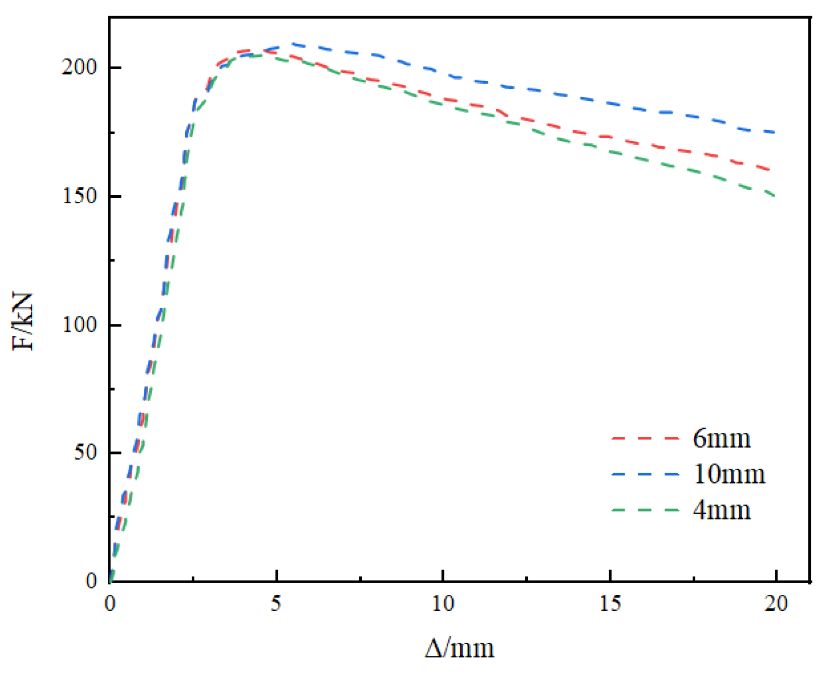
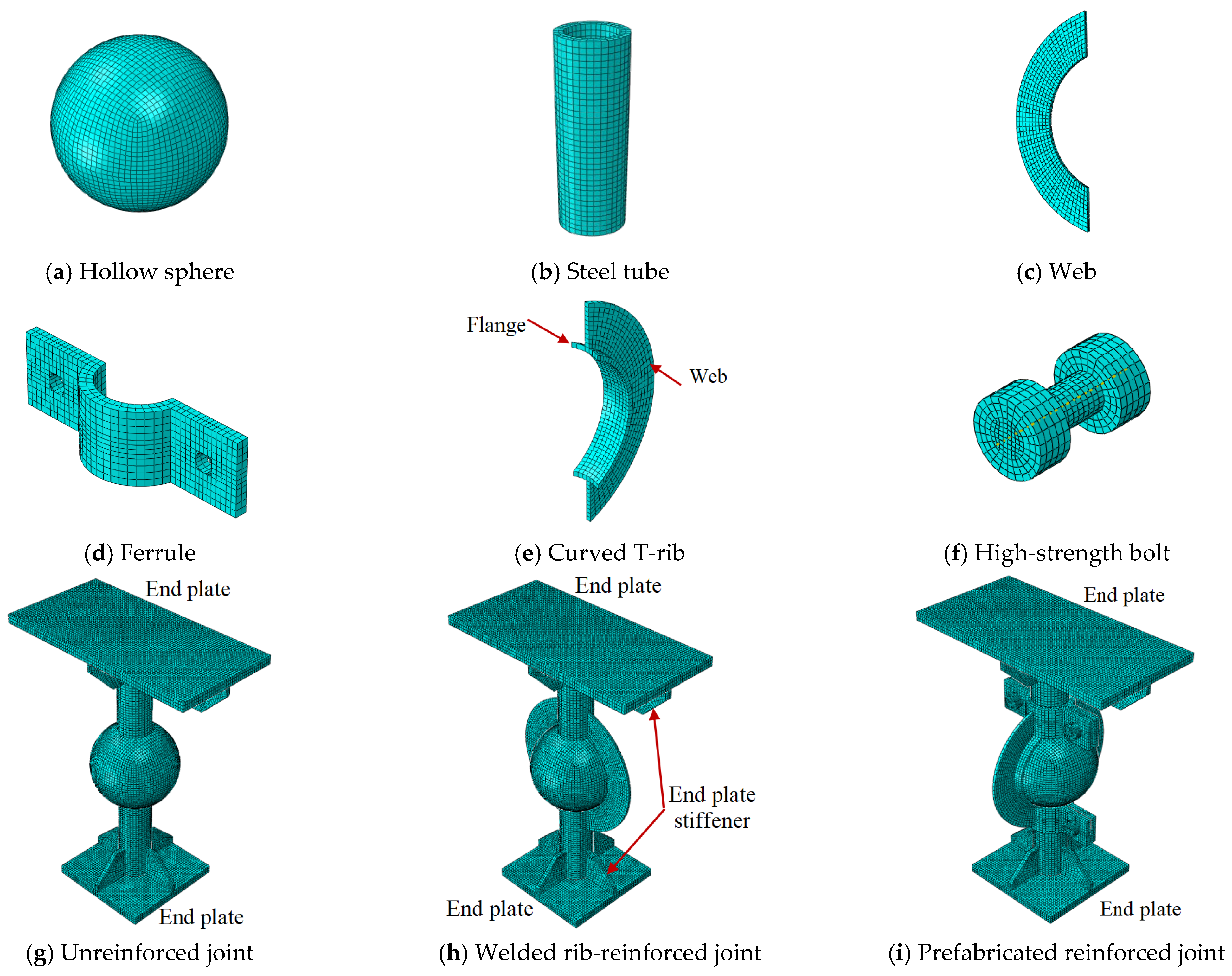
For prefabricated reinforced hollow spherical joints, the compressive bearing capacity was often determined by local compressive buckling failure. Using the mesh of unreinforced hollow spherical joints as an example, the compressive load–displacement curves of hollow spherical joints with mesh sizes of 4 mm, 6 mm, and 10 mm were compared and analyzed, as shown in Figure 2, which illustrates that mesh sizes significantly affected the numerical analysis results of the joints. The smaller the mesh size was, the closer the analysis results were to reality. When the mesh size was 6 mm, the load–displacement curve was very close to the analysis results when the mesh size was 4 mm. Therefore, to balance accuracy and computational cost, the bolt mesh size was set to 3 mm, whereas a 6 mm mesh size was used for the remaining components. The mesh configurations of all model components are shown in Figure 3.

2.1.2. Constitutive Model

The von Mises criterion was adopted to define yielding of steel, and kinematic hardening was used to represent the post-yield plastic response. A bilinear elastic–plastic constitutive model was employed for both the steel and the high-strength bolts. In the FE model, the steel elastic modulus and yield strength were obtained from the true stress–strain curves of steel, and Poisson’s ratio was set to 0.3. The material parameters are listed in Table 1.

2.1.3. Boundary Conditions

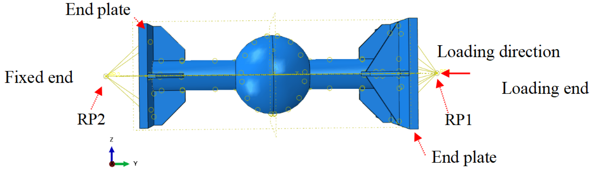
In the experiment, the welded hollow spherical joints had a fixed end and a loading end. The fixed end was connected to the reaction frame using a high-strength bolt and end plate, whereas the loading end was connected to the MTS actuator using a high-strength bolt and the other end plate [24]. The fixed end was idealized as a rigid connection, whereas the loading end was allowed to translate only in the axial direction. The boundary conditions and loading scheme of the FE model are illustrated in Figure 4. First, the outer surface of the end plate for the loading end was coupled to a reference point (RP1) at its center. The outer surface of the one for the fixed end was coupled to the other reference point (RP2) at its center, as shown in Figure 4. A fully fixed constraint was applied to RP2. At RP1, all degrees of freedom were constrained except for translation in the Y direction. A prescribed displacement was applied in the negative Y direction to investigate the joint response under monotonic compression. The displacement increment matched the loading-step size used at the loading end in the experiment.

2.1.4. Analysis Step Definition

For the unreinforced and welded-reinforced specimens, a single analysis step was defined. Geometric and material nonlinearities were considered, and the large-deformation option was activated. An axial compressive displacement consistent with the experimental protocol was applied at the coupled reference point RP1. For the prefabricated reinforced specimens, three analysis steps were defined to simulate bolt pretension and subsequent loading. In the first step, pretension forces of 80 kN were applied to Grade 8.8 M16 high-strength bolts, in accordance with JGJ82-2011 Technical Specification for High-Strength Bolt Connections of Steel Structures [29]. In the second step, the current bolt length was fixed to represent the locking effect and sustained clamping state after pretensioning. In the third step, an axial displacement consistent with the experimental loading scheme was applied at RP1 on the loading end.

2.1.5. Contact Definition

For the unreinforced and welded-reinforced joints, welded interfaces were modeled using “tie” constraints, including the connections between the hollow sphere and steel tube, steel tube and end plate, end plate and stiffener, stiffener and steel tube, as well as between the welded rib plate and the hollow sphere and steel tube. In the prefabricated reinforced joint model, high-strength bolts were simplified by representing the shank as a cylinder with a diameter equal to the effective bolt diameter, and the nut as a cylinder of corresponding dimensions. Hard contact was defined between the bolt and the ferrule, the ferrule and the steel tube, and the T-rib flange and the hollow sphere. Tangential behavior was modeled using Coulomb friction with a coefficient of 0.3, whereas normal behavior was defined using a linear contact formulation with a contact stiffness of 1000 N/mm.
In the prefabricated reinforced joint model, the friction coefficient was set at 0.3, determined based on typical friction coefficient values for untreated steel surfaces under high-strength bolt connections as specified in relevant specifications and literature. The bolt pretension was applied according to the provisions of JGJ82-2011 [29] for the corresponding bolt specifications and performance levels. These parameters directly affected the anti-slip capability of the contact interface and the timing of slip initiation between the ferrule and the steel tube. Changes in the friction coefficient or pretension force can alter the load transfer path and internal force distribution, thereby affecting the collaborative deformation capacity of the joint, initial stiffness, bearing capacity, and energy dissipation performance.

2.1.6. Initial Geometric Imperfections

Because geometric imperfections inevitably arise during fabrication, transportation, and installation, an elastic buckling analysis was first performed in ABAQUS to extract the first five buckling modes for evaluating their influence on joint stiffness and bearing capacity. The ABAQUS input file was subsequently modified, and the first buckling mode was selected and scaled by an imperfection amplitude factor of 1/300 [28] before being introduced as the initial geometric imperfection.

2.2. Model Validation

Guo et al. [11] proposed a reinforcement scheme using a unilateral annular welded rib for hollow spherical joints and conducted axial compression tests on welded hollow spherical joints. Under axial compression, failure modes, load–displacement responses, and change rules in bearing capacity before and after reinforcement were systematically analyzed. The specimen design parameters and mechanical indices are listed in Table 2. Two groups of welded hollow spherical joint specimens were designed for the compression experiment. The hollow sphere and steel tube had dimensions of 200 mm × 6 mm and 60 mm × 4 mm, respectively. In the test specimens, the hollow sphere, steel tube, and welded curved rib were fabricated from Q235 steel. The yield strengths of the steel used for different components are given in Table 2.
Ref. [24] analyzed the influence of different reinforcement methods, the number of welded ribs, the width-to-thickness ratio (b/t1) of the T-shaped rib web, and the pretension force of high-strength bolts on the seismic performance of joints through cyclic loading tests. Specimen 3-3 from Ref. [24] was chosen to validate the FE model presented in this paper for simulating the friction slip phenomenon between the ferrule and the steel tube. The tensile properties of the steel used in specimen 3-3 are shown in Table 2, and the geometric structure diagram is shown in Ref. [24].
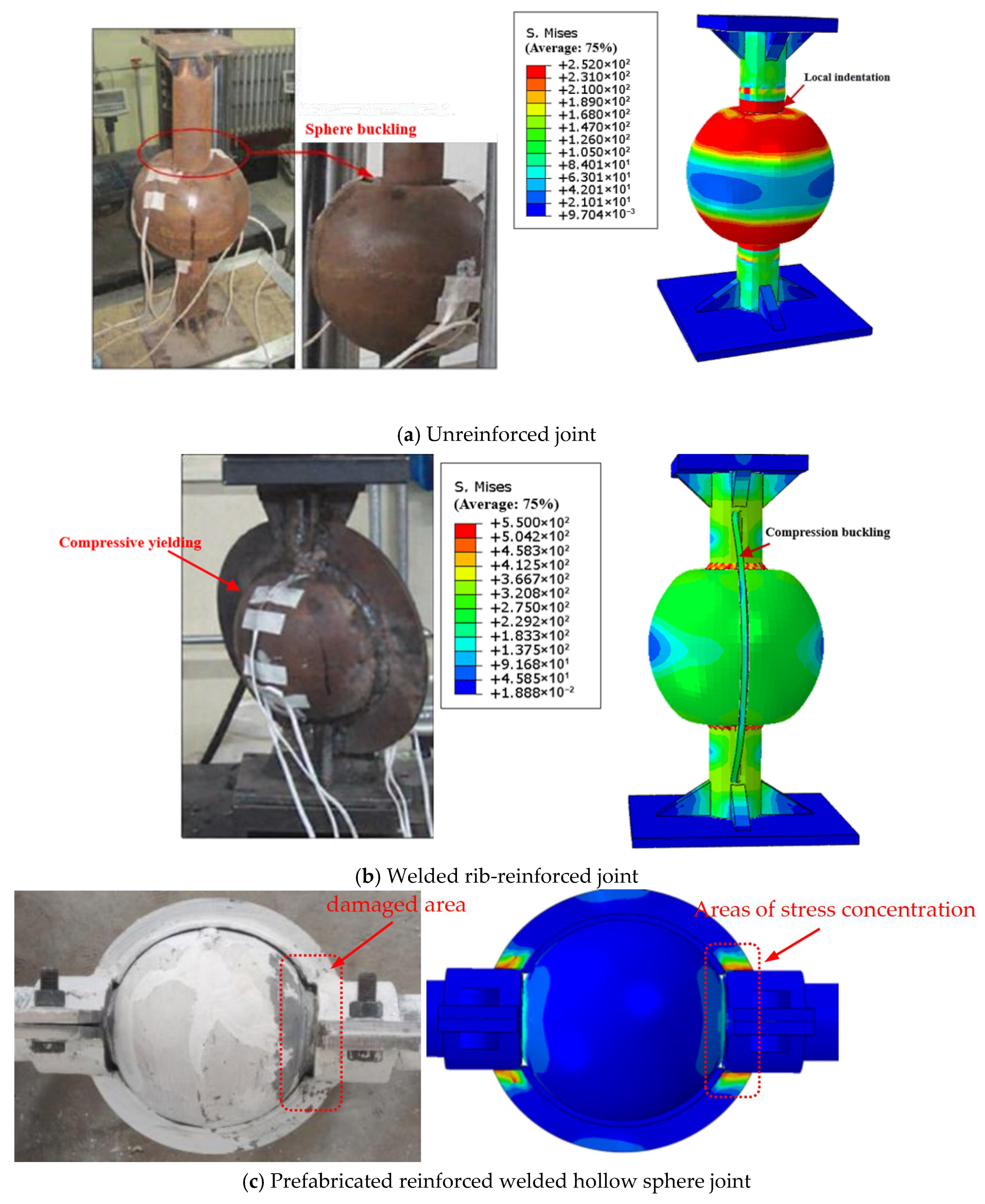
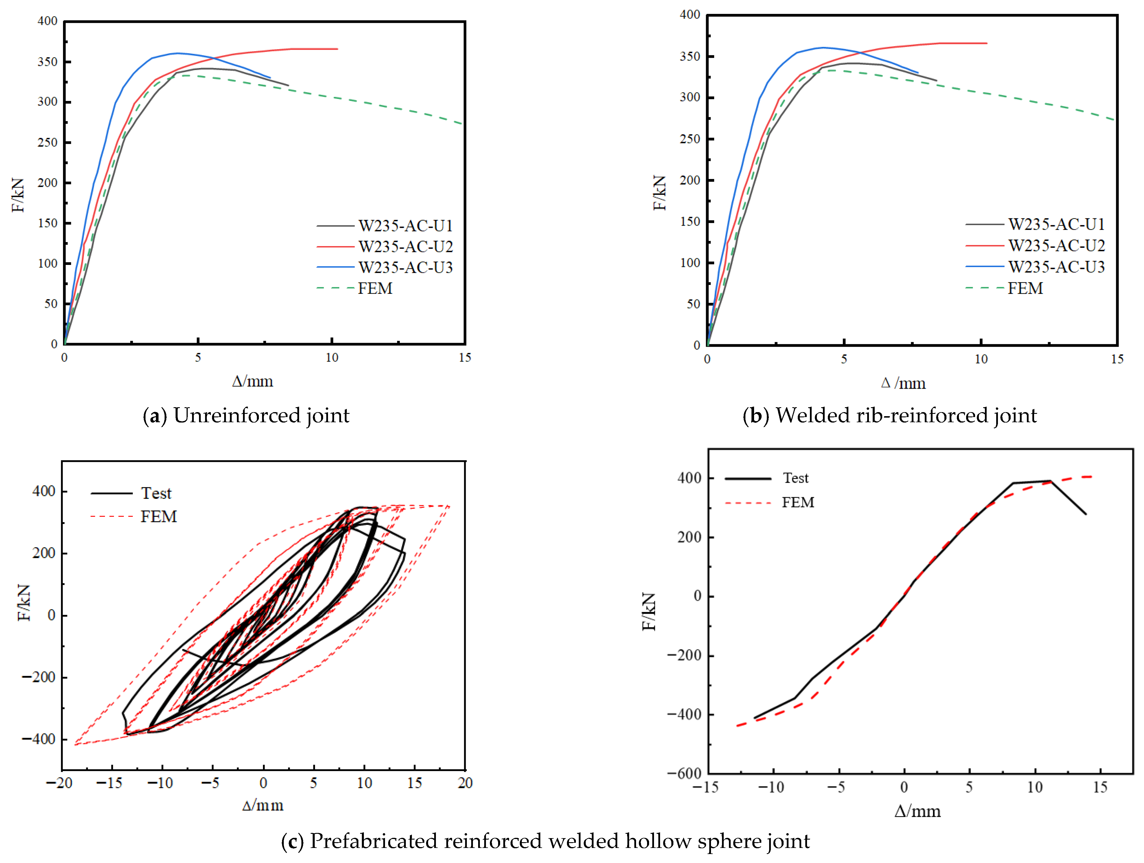
Figure 5 and Figure 6 compare failure modes and load–displacement curves of the joints obtained from experiments and FE analysis, respectively. A comparison of bearing capacity between them is presented in Table 3. As shown in Figure 5, the failure modes predicted by the FE model were consistent with the experimental observations. The model can effectively simulate local buckling of the hollow sphere and the buckling response of the welded annular stiffening rib under compression.
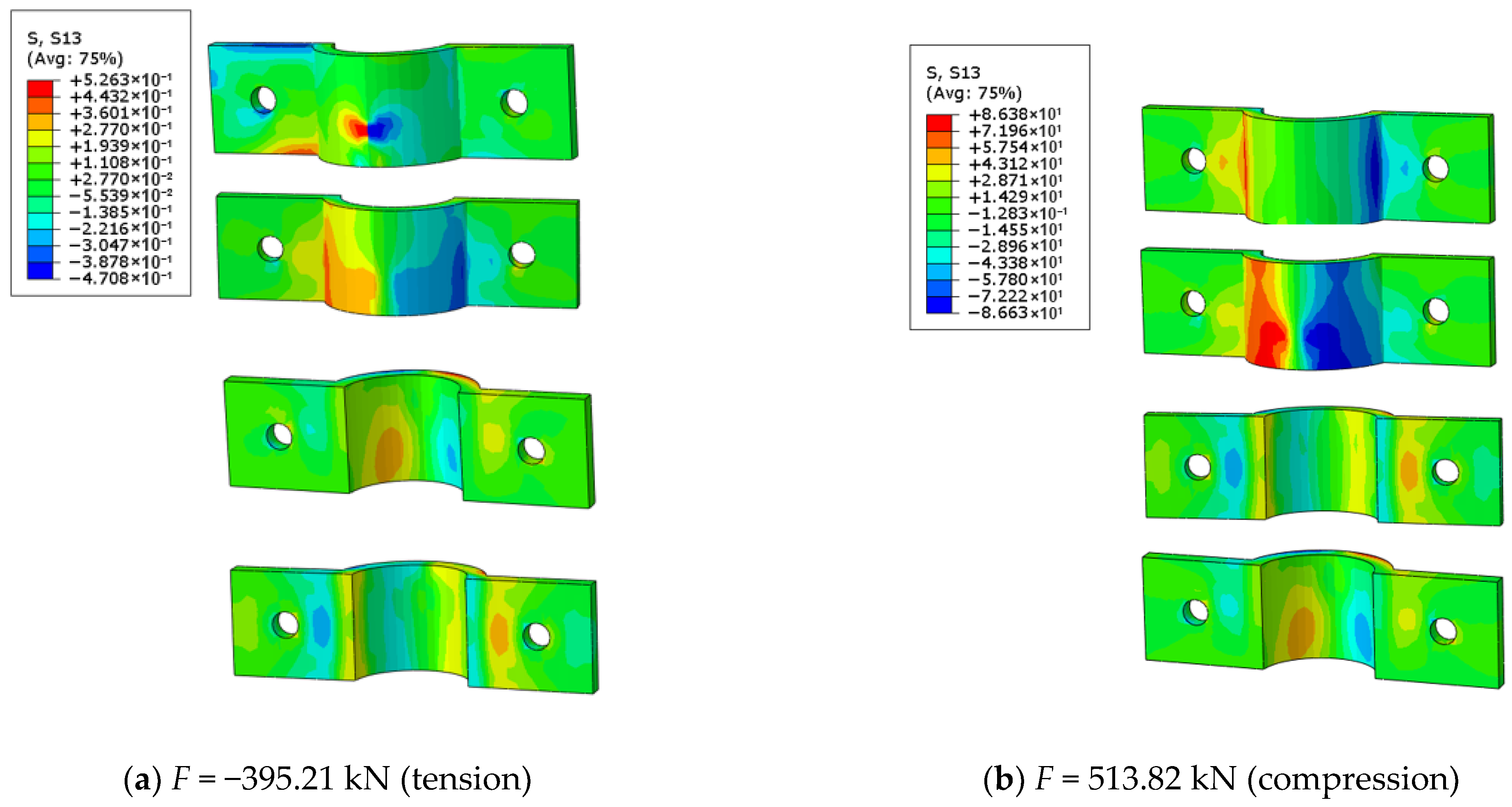
Additionally, Figure 5c illustrates that when subjected to cyclic tension and compression loads, the connection weld between the steel tube and the sphere of the prefabricated reinforced hollow spherical joint failed, resulting in significant shedding of lime powder near the fracture zone. All of which indicated that the elastic–plastic deformation in this area was large. In the FE analysis, the stress at the joint between the steel tube and the sphere, as well as in its vicinity, was greater, indicating that a fracture was more likely to occur at this location than at others. The reinforcement mechanism of the assembled reinforced spherical joint was that part of the external load acting on the steel tube was transmitted to the sphere, and the other part was transmitted to the reinforcement component through the friction force generated between the ferrule and the steel tube. The reinforcement component distributed part of the load over the spherical surface, thereby enhancing the bearing capacity of the joint. The FE analysis revealed high stress in the connection area between the T-shaped rib and the ferrule, indicating that the internal force generated by the reinforcement component was significant. As shown in Figure 6, the calculated load–displacement curves agreed well with the experimental trends. However, the numerical model predicted a higher initial stiffness than that observed experimentally. This discrepancy was mainly attributable to the idealized boundary conditions in the FE model. In the experiments, rigid-body displacements occurred to varying degrees during loading. In addition, residual stresses in the welds were not included, which further contributed to the higher initial stiffness predicted by the FE analysis. Nevertheless, Table 3 showed that discrepancies between FE predictions and experimental results for joint bearing capacity were within 7%, indicating that the present model reliably captured the axial compressive load-bearing performance of reinforced welded hollow spherical joints.
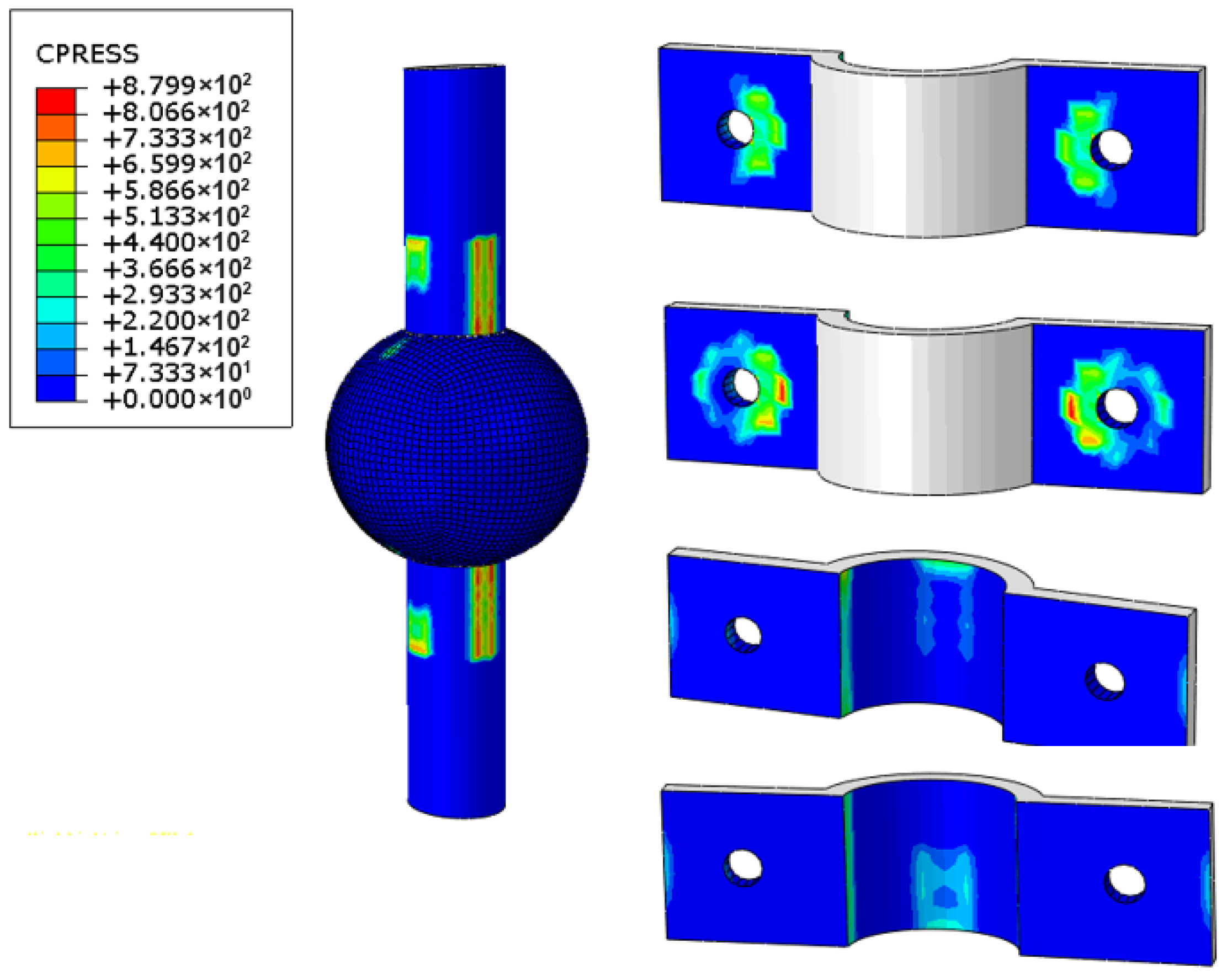
Figure 7 and Figure 8 show the stress contours of the contact pressure and shear stress at the interface between the steel tube and the ferrule of specimen 3-3, respectively. Figure 7 showed that when the bolt pretension force was applied, the contact compressive stress was generated between the steel tube and the ferrule. Figure 8 clarified that the interfacial shear stress increased as the load enhanced, indicating that the interfacial friction force created by the bolt pretension force was more effective in transferring the internal forces experienced by the steel tube. Therefore, the FE model in this paper can effectively simulate this force transfer process, reproducing the failure mechanisms and deformation characteristics before and after reinforcement.

3. Parametric Analysis

Ref. [24] experimentally investigated the seismic performance of this type of prefabricated joint under cyclic loading, comparing it with unreinforced joints. The study also examined the associated failure mechanisms, load-bearing performance, and energy dissipation capacity. To quantitatively evaluate load-bearing performance under axial compression, a systematic parametric analysis was conducted with T-rib web width b, web thickness t1, ferrule thickness t2, hollow-sphere diameter D, and bolt pretension force fv as variables. The specimen design satisfied the detailing requirements of CECS 77: 96 Technical code for Strengthening of Steel Structures [30]. The parameter values were defined as follows. The T-rib web width was set to 20, 40, 60, and 80 mm, corresponding to T-rib flange height (h)-to-web width ratios (h/b) of 0.00, 0.33, 0.67, and 1.00, respectively. On each side, two bolts were arranged on each ferrule in a single row, and bolt pretension forces were set to 20, 40, 60, and 80 kN. The detailed parameters are listed in Table 4.

3.1. Load–Displacement Characteristics

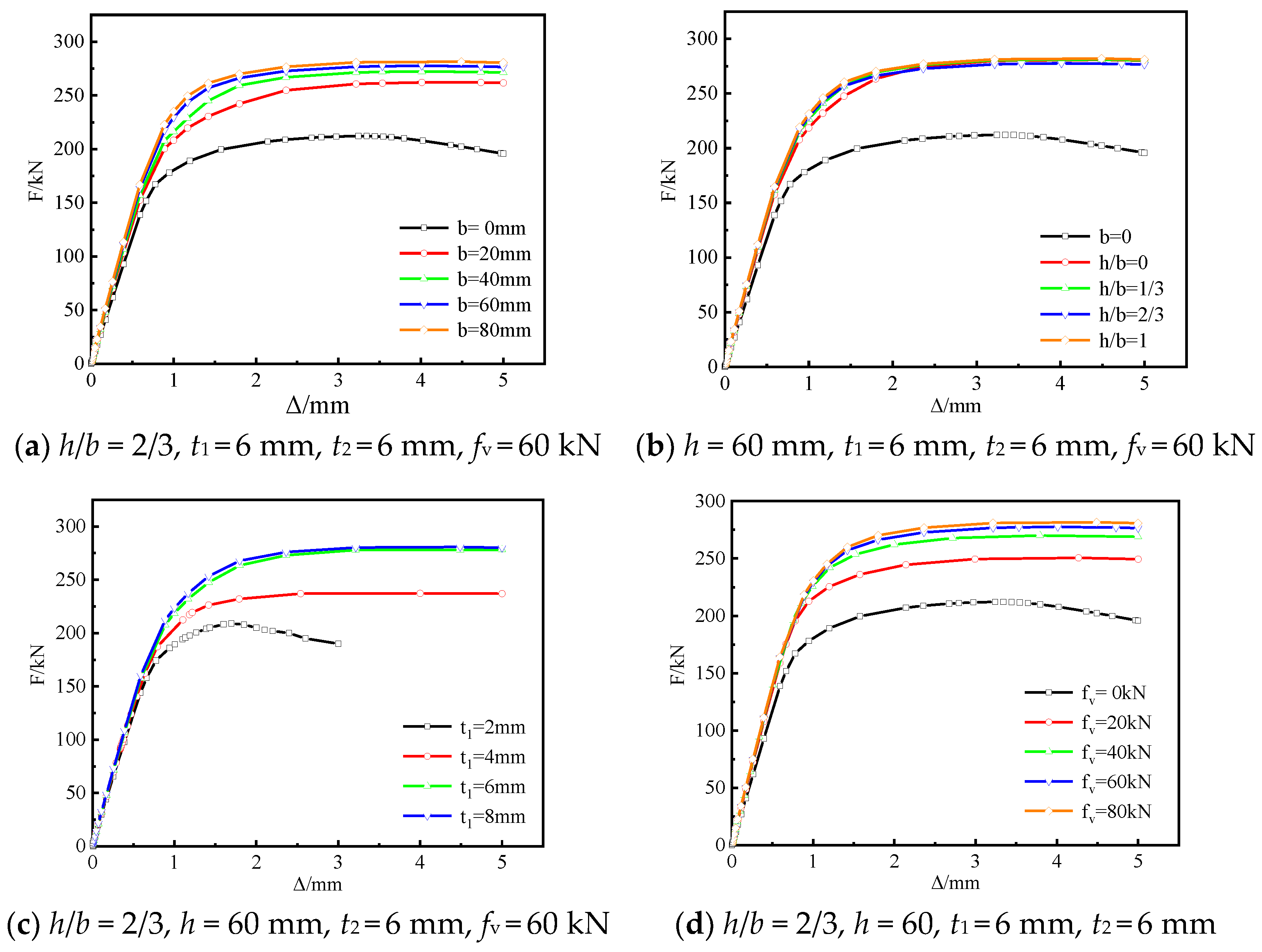
The compressive load–displacement curves of the prefabricated reinforced hollow spherical joint were obtained from systematic FE analyses. Because the calculated load–displacement curves were similar across all numerical models, only a representative case was presented for comparison (Figure 9). Figure 9 showed that, for variations in T-rib web width b, height-to-width ratio h/b, web thickness t1, and ferrule thickness t2, the load–displacement response increased approximately linearly up to the yield load. Beyond yielding, the curve slope gradually decreased, indicating similar patterns of plastic development and failure. As shown in Figure 9a,c, with increasing web width b and web thickness t1, the bearing capacity of the prefabricated reinforced joint continued to increase, whereas the marginal gain gradually diminished. The increase was mainly attributed to the enhanced strength of the reinforcing components. Once the component strength became sufficiently high, the bearing capacity was governed primarily by the friction force between the ferrule and steel tube, consistent with the behavior in Figure 9d. Increasing bolt pretension significantly improved load-bearing performance, and the load–displacement curves exhibited distinct differences. The behavior arose because the reinforcing system transferred load mainly through the friction force between the ferrule and the steel tube, and the available frictional resistance was governed mainly by bolt pretension and the stiffness of the reinforcing components, including the ferrule. Overall, the mechanical response of the prefabricated reinforced joint was determined by the strength and stiffness of the reinforcing components and the friction force between the ferrule and the steel tube.

3.2. Load-Bearing Performance Analysis

In engineering design, there may be coupling effects between some variables. For example, when the specifications of the bolts differ, the edge distance, end distance, and bolt spacing on the connecting plate will be affected. Therefore, when studying the influence of bolt pretension force on the bearing capacity of reinforced spherical joints, if the bolt specifications were changed, in addition to the change in bolt pretension force, the size of the ferrule would also change due to the need for installation space, which made it difficult to quantify which factor caused the change in bearing capacity. Based on this, this paper chose the single variable control method to study the influence of relevant parameters on the bearing capacity of reinforced spherical joints. That was, when analyzing the influence of a certain parameter on the bearing capacity of the joint, only the value of the parameter was changed, while the other parameters were kept unchanged. The purpose was to quantitatively analyze the influence of a single parameter on the bearing capacity of the joint and to clarify its changing trend. The advantage of this method is that it can avoid the interference of other variables, so that the influence level can be accurately evaluated in the joint design.
In addition to analyzing the influence of bolt pretension force on the bearing capacity of the joints, all the prefabricated reinforced hollow spherical joints in this study were applied with the corresponding bolt pretension force according to the specification JGJ82-2011 [29], which made it close to the engineering design practice.

3.2.1. Effect of T-Rib Web Width

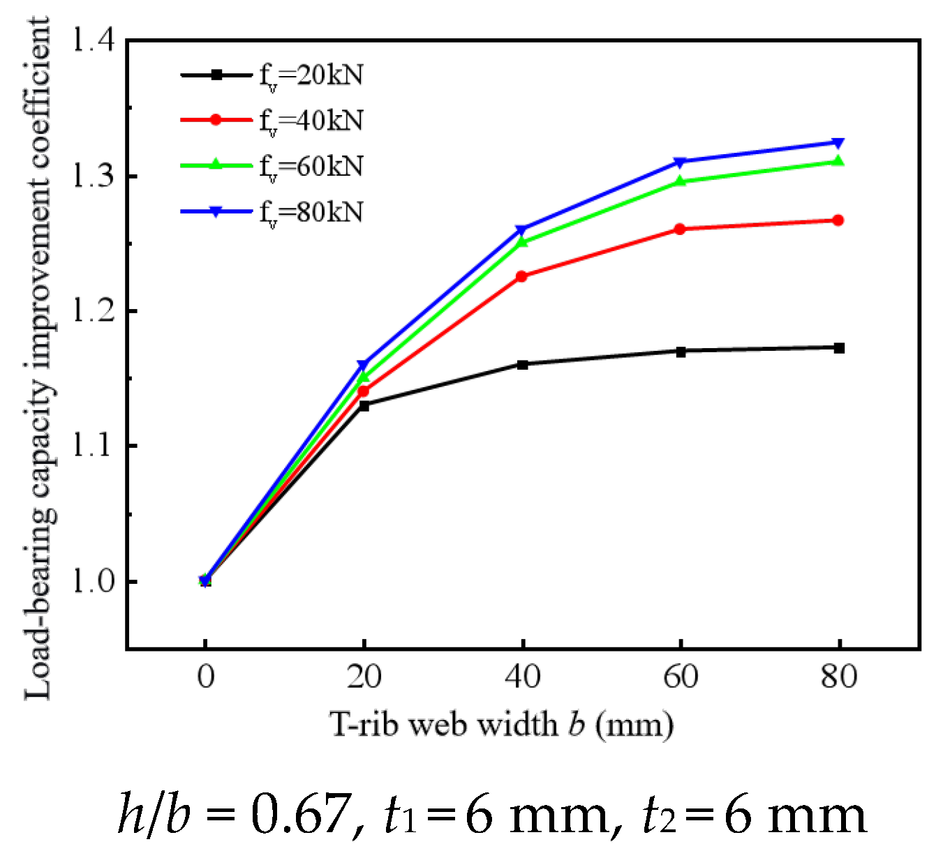
Figure 10 shows the effect of T-rib web width b on the bearing capacity of the prefabricated reinforced hollow spherical joint, with all other parameters held constant. The T-rib web width b ranged from 0 to 80 mm. Figure 10 indicates that the bearing capacity of the prefabricated reinforced hollow spherical joint increased with web width, and the magnitude of the increase depended strongly on bolt pretension. For example, at a bolt pretension of fv = 20 kN, increasing the web width from 0 to 20 mm improved the bearing capacity by less than 15%. Further increases in b produced little additional gain because the low pretension provided insufficient friction at the ferrule and steel tube interface, leading to slip and preventing full mobilization of the reinforcing components. At fv = 80 kN, increasing the web width from 0 to 20 mm enhanced the bearing capacity by more than 15%. Increasing b from 0 to 80 mm increased the bearing capacity of the prefabricated reinforced joint by 33%. These results indicated that, when sufficient friction existed at the ferrule and steel tube interface, increasing b significantly enhanced reinforcement effectiveness. The improvement can be attributed to the higher strength and stiffness of the reinforcing components provided by a larger web width, which increased the share of externally applied compressive load carried by the reinforcement. As a result, compressive demand on the hollow sphere was reduced, and the overall joint capacity improved.

3.2.2. Effect of T-Rib Web Thickness

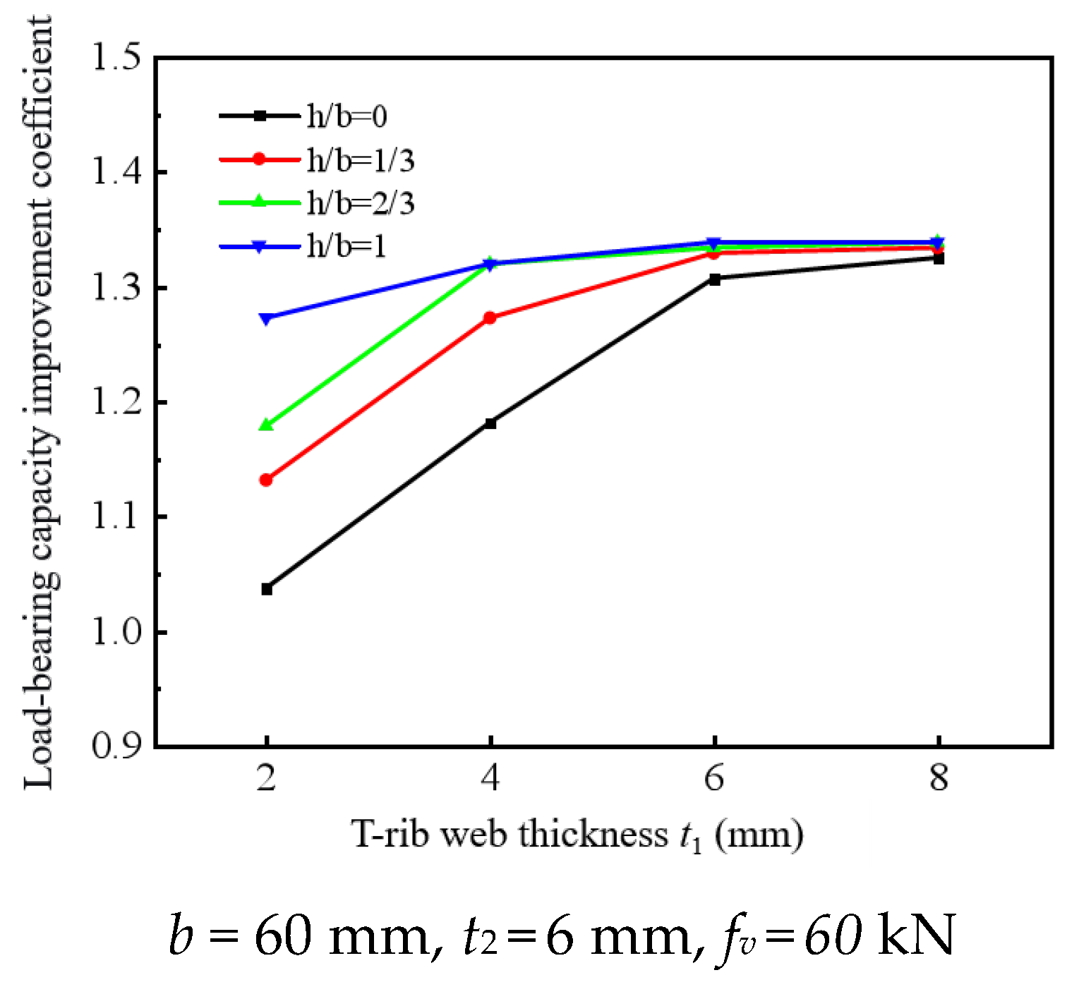
Figure 11 shows the effect of the T-rib web thickness t1 on the bearing capacity of the prefabricated reinforced hollow spherical joint while all other parameters are held constant. Figure 11 displayed that the bearing capacity increased as the T-rib web thickness improved, whereas the incremental gain gradually diminished. When the h/b = 0, increasing the web thickness from 2 mm to 6 mm improved the joint bearing capacity by approximately 30%. Increasing the web thickness from 6 mm to 8 mm did not significantly alter the bearing capacity. This behavior was mainly attributed to the absence of the T-rib flange: the web exhibited low out-of-plane stiffness and was prone to out-of-plane buckling under compressive loading. Increasing the web thickness improved the out-of-plane stiffness and enabled the reinforcing effect to be more fully mobilized. Under relatively large compressive loads, slip may occur because of insufficient friction between the ferrule and the steel tube, which reduces the reinforcement effectiveness. When the h/b = 1.0, increasing the T-rib web thickness did not markedly improve the bearing capacity of the hollow spherical joint. For example, increasing the T-rib web thickness from 2 mm to 8 mm increased the bearing capacity by less than 10%. The primary reason was that the web and the flange provided mutual restraint, which enhanced the stiffness and strength of the T-rib. When h/b = 1.0, the T-rib plate can satisfy the joint reinforcement demand based on its inherent strength and stiffness. Therefore, the T-rib flange-height-to-web-width ratio is recommended to be h/b = 1.0, and the T-rib web thickness t1 should be no less than the wall thickness of the welded hollow sphere.

3.2.3. Effect of Ferrule Thickness

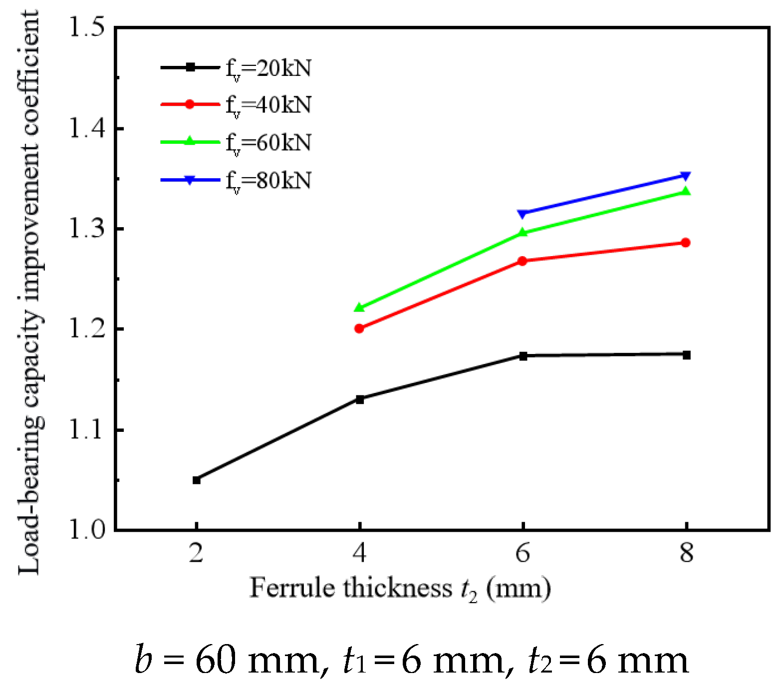
Increasing the ferrule thickness reduces its deformation under the designed bolt pretension force, thereby generating greater pre-compressive action between the ferrule and the steel tube and increasing the friction between them. The increase in friction enhances the reinforcement effectiveness of the reinforcing components. Figure 12 shows the effect of ferrule thickness on the bearing capacity of the reinforced hollow spherical joint. The bearing capacity increased gradually as the ferrule thickness strengthened. For example, when the bolt pretension force was fv = 20 kN, increasing the ferrule thickness from 2 mm to 6 mm improved the bearing capacity of the reinforced joint by approximately 13%, indicating a relatively limited improvement. When the ferrule thickness increased further from 6 mm to 8 mm, the bearing capacity remained essentially unchanged. The primary reason was that the relatively low bolt pretension force led to an inconspicuous reinforcement effect. For instance, the enhancement in bearing capacity at fv = 80 kN was markedly greater than that at fv = 20 kN.

3.2.4. Effect of Welded Hollow Sphere Diameter

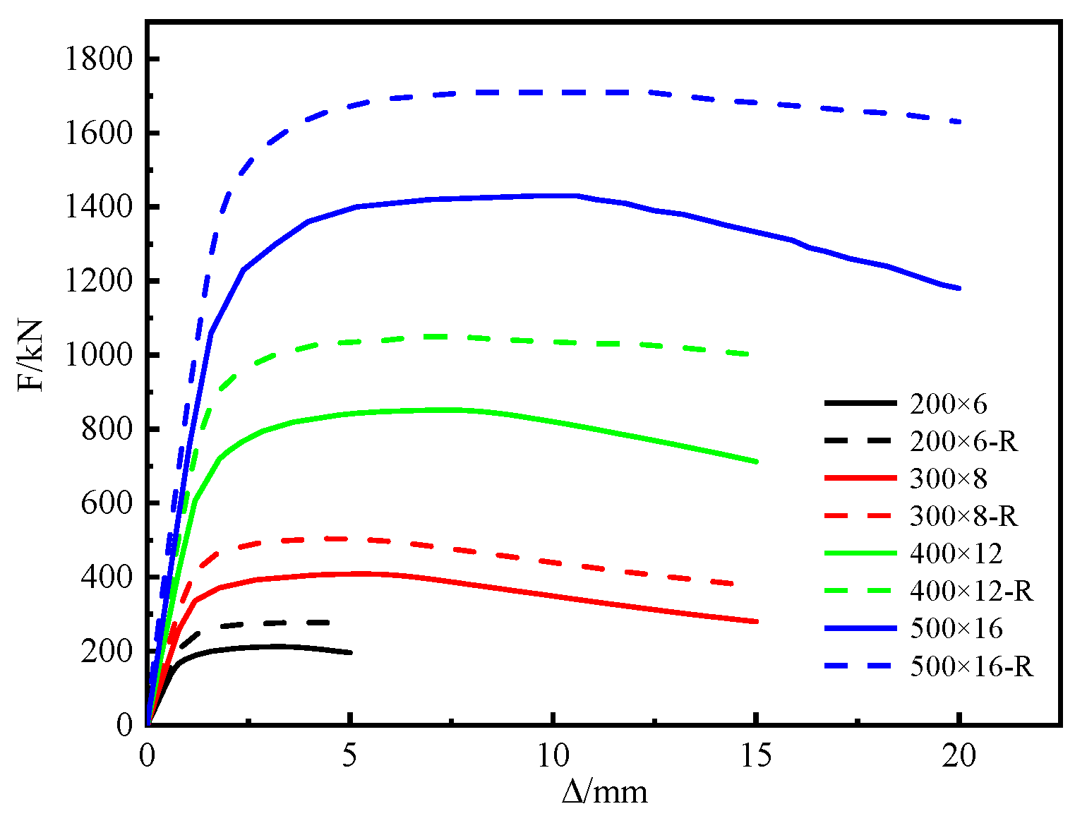
To investigate the effect of the welded hollow sphere diameter D on the reinforcement performance of the joint, welded hollow spheres with diameters of 200 mm, 300 mm, 400 mm, and 500 mm were selected. The ratio of steel tube diameter to hollow sphere diameter was kept constant at d/D = 3.33, and the steel tube thickness was set equal to the wall thickness of the hollow sphere. The remaining design parameters are listed in Table 5. A single-row bolted connection was adopted throughout, and the height-to-width ratio of the T-rib was set to 0.33. The thicknesses of the T-rib flange, T-rib web, and ferrule were taken to be identical to the wall thickness of the hollow sphere. Through systematic FE analysis, the bearing capacity of the unreinforced and prefabricated reinforced hollow spherical joints with different hollow sphere diameters was obtained. The results are summarized in Table 5.
Figure 13 shows the load–displacement curves of unreinforced and reinforced hollow spherical joints with different hollow sphere diameters. Before the peak load, the load–displacement curves of unreinforced and prefabricated reinforced hollow spherical joints were generally similar. After the peak load, the difference between the curves became more pronounced as the hollow sphere diameter increased. For example, in the unreinforced welded hollow spherical joint labeled 500 × 16, the bearing capacity exhibited a marked drop after the peak load because the hollow sphere rapidly indented under local compressive stress. In contrast, in the reinforced joint labeled 500 × 16-R, the post-peak descending branch of the load–displacement curve was not pronounced because the supporting effect of the reinforcing components reduced the extent of local indentation of the hollow sphere. The load–displacement curves showed that prefabricated reinforcement enhanced the bearing capacity of welded hollow spherical joints with varying diameters. As the diameter-to-thickness ratio of the hollow sphere (D/ts) decreased, the increment in bearing capacity of the prefabricated reinforced welded hollow spherical joint decreased. The primary reason was that a smaller D/ts increased the buckling stiffness of the hollow sphere under external pressure and enhanced its resistance to out-of-plane loading. Under compressive loading, the reinforcing components primarily improved the overall bearing capacity by providing out-of-plane support to the hollow sphere. When the hollow sphere stiffness was relatively high, the effectiveness of this support was further reduced.

4. Predictive Model for the Compressive Load-Bearing Capacity of the Prefabricated Reinforced Hollow Spherical Joint

In the Chinese code JGJ 7-2010 Technical Specification for Space Grid Structures [28], the calculation method for the compressive bearing capacity of joints with hollow-sphere outside diameters ranging from 120 mm to 900 mm was provided, as expressed in Equation (1):
N 0 = ( 0.29 + 0.54 d D ) η 0 π t s df
where η 0 was the capacity modification factor for large-diameter hollow-sphere joints: when the hollow-sphere diameter D ≤ 500 mm, η 0 = 1.0 , and when the hollow-sphere diameter D > 500 mm, η 0 = 0.9 ; f denoted the design value of the tensile strength of steel, and the measured (actual) tensile strength of steel was adopted in this study. Considering the supporting effect of the reinforcing components on welded hollow-sphere joints under compressive loading, Equation (1) was systematically modified to establish a predictive model for the compressive bearing capacity of the prefabricated reinforced welded hollow spherical joint. The enhancement coefficient of compressive bearing capacity for the prefabricated reinforced joint, the Rc was defined as:
R c = N R N 0
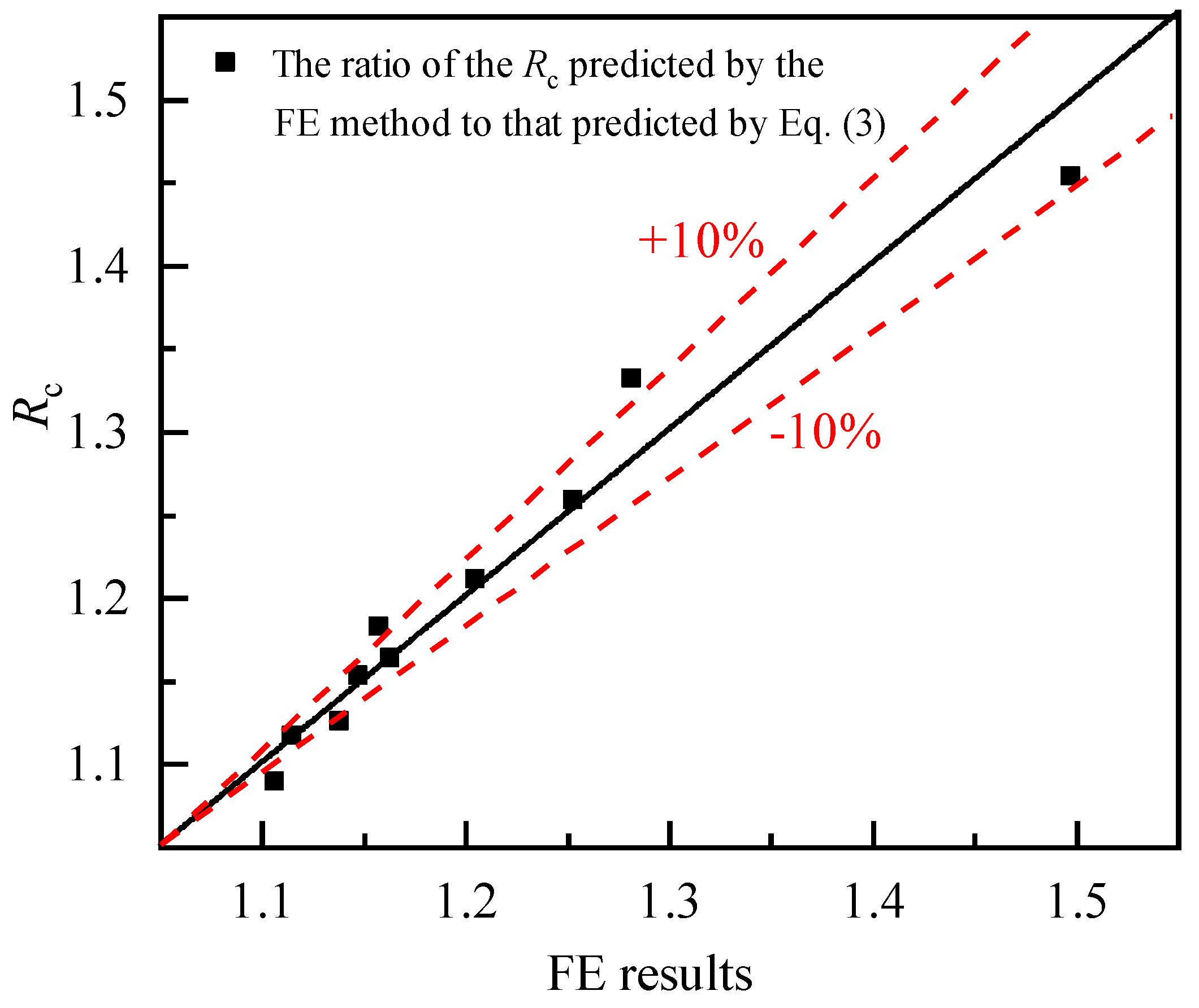
where N0 was the compressive bearing capacity of the unreinforced welded hollow spherical joint, and NR presented one of the prefabricated reinforced joints. Since the compressive bearing capacity of the welded hollow spherical joint was influenced by multiple factors, this section employed FE analysis to investigate the enhancement coefficient (Rc) under variations in three parameters, namely, hollow-sphere wall thickness (ts), steel tube diameter (d), and tube-to-sphere diameter ratio (d/D), while keeping the other parameters unchanged, and the results are summarized in Table 6.
Using the least-squares method, multivariate linear regression analysis was conducted on the enhancement coefficient of axial compressive bearing capacity for the prefabricated reinforced welded hollow spherical joint. A calculation formula for the enhancement coefficient Rc was then obtained, as expressed in Equation (3):
R c = a · x + b
where b was a constant, b = 2.24539; a presented a coefficient vector, a = (−0.06063, 0.00157, −0.95549); x was the variable-parameter vector, x = (ts, d, d/D); and a · x denoted the dot product of the two vectors.
Generally, the structural capacity of shells was typically scaled nonlinearly with geometric parameters. However, the Rc was linear with parameter x (ts, d, d/D) from Equation (3). The main reason was that the range of parameters involved in this study was small, and the variation range of parameters was low. Therefore, there was a linear trend between Rc and the above parameters, resulting in the scope of application of Equation (3) was not universal. In the future, this study will strengthen the research on the theoretical model of the bearing capacity of prefabricated reinforced hollow spherical joints, so as to ensure that the design requirements of the bearing capacity of assembled reinforced hollow spherical joints can be met in a wider range.
Figure 14 presents a comparison between the FE simulation results and the theoretical values of the enhancement coefficient Rc for compressive bearing capacity. The results indicated that the discrepancy between the simulated and theoretical values was within ±10%, demonstrating that Equation (3) reasonably captured the variation in the enhancement coefficient Rc for the compressive bearing capacity of the prefabricated reinforced hollow spherical joint with the key design parameters ts, d, and d/D.
The axial compressive bearing capacity of the prefabricated reinforced joint was obtained by multiplying the bearing capacity of the unreinforced joint by the axial compressive bearing capacity enhancement coefficient Rc, as expressed in Equation (4):
N c = R c · ( 0.29 + 0.54 d D ) η 0 π t s df
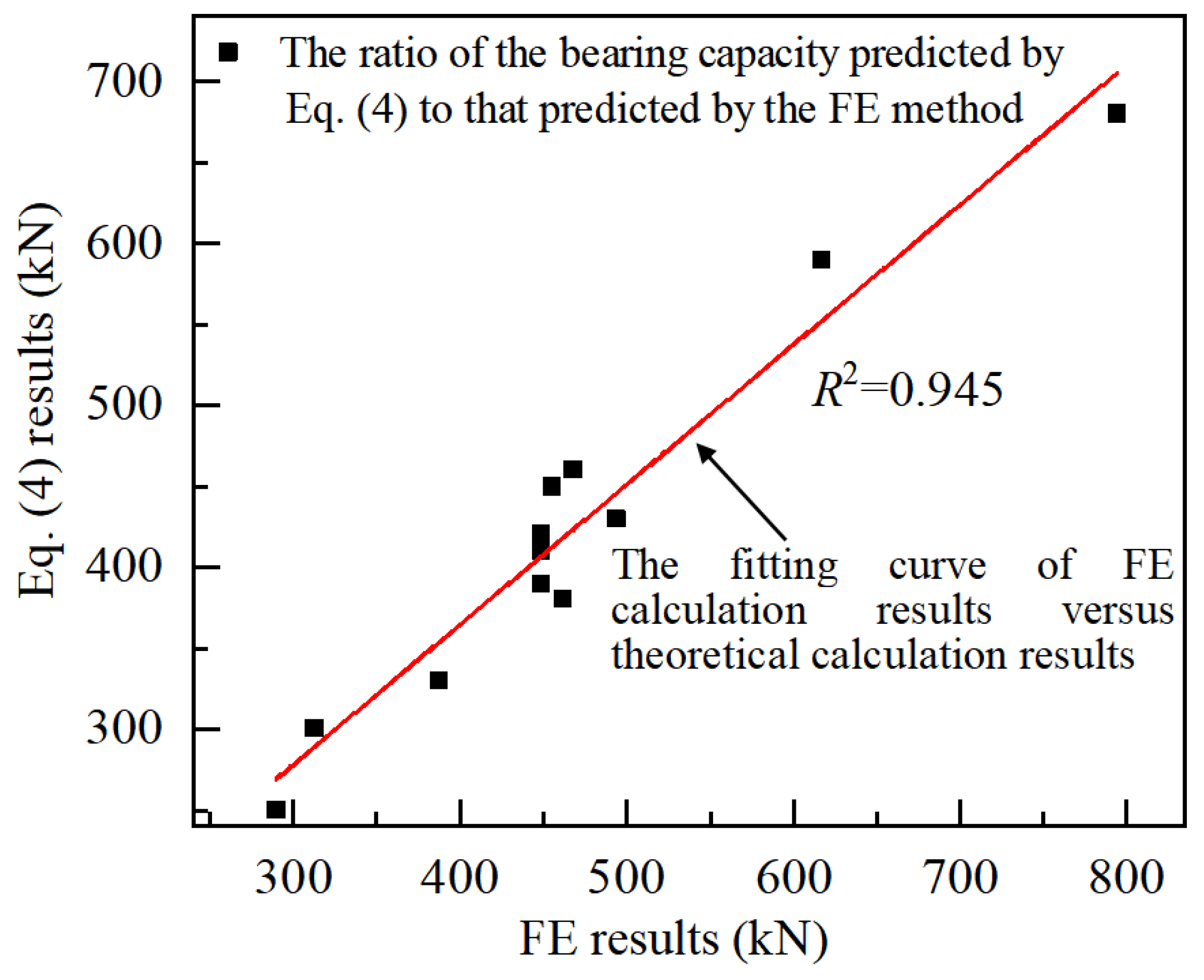
Figure 15 compares and analyzes the bearing capacity of prefabricated reinforced hollow spherical joints calculated by Equation (4) and the FE method. Figure 15 showed that the coefficient (R2) of determination between the theoretical prediction value and the FE calculation value was 0.945, indicating that there was a strong correlation between them, which can provide a reference for the design of the compressive bearing capacity of prefabricated reinforced hollow spherical joints.
However, it should be noted that Equation (4) applied to the compressive bearing capacity assessment of the prefabricated reinforced hollow spherical joint under the following conditions: hollow-sphere diameter D ≤ 500 mm; hollow-sphere wall thickness t = 6~12 mm; steel tube diameter d = 60~150 mm; diameter ratio d/D = 0.30~0.39; single-row bolted connections; two groups of prefabricated T-ribs symmetrically arranged outside the sphere, with a rib-plate width of D/3 and a height-to-width ratio of 0.33; and rib-plate and ferrule thicknesses equal to the sphere wall thickness. The conditions collectively define the scope of application of Equation (4). In practical engineering applications, it is recommended to conduct supplementary verification when the parameters exceed the range.

5. Conclusions

This study investigated the prefabricated reinforced welded hollow spherical joint and developed a three-dimensional FE model that accounted for geometric nonlinearity, material nonlinearity, and initial geometric imperfections. The model reliability was validated against experimental results. The effects of key parameters, including the T-rib web width and thickness, ferrule thickness, and welded hollow sphere diameter, on the compressive behavior of the prefabricated reinforced hollow spherical joint were investigated. A predictive model for the compressive bearing capacity of the prefabricated reinforced hollow spherical joint was proposed, incorporating the supporting effect of the reinforcing components and the influences of welded hollow sphere diameter, steel tube diameter, and tube-to-sphere diameter ratio. The main conclusions are summarized as follows:
(1)
The three-dimensional solid FE model that accounted for geometric nonlinearity, material nonlinearity, and initial geometric imperfections can effectively predict phenomena such as local indentation of welded hollow spherical joints and rib-plate buckling under compressive loading. The discrepancy between the FE predictions and the experimental results for compressive bearing capacity was within 7%, indicating that the model was suitable for parametric analyses of joint load-bearing performance.
(2)
The strength and stiffness of the reinforcing components, together with the friction between the ferrule and the steel tube, were the primary factors governing the mechanical behavior of the prefabricated reinforced joint. Under compression, the reinforcing components provided out-of-plane support to the hollow sphere, thereby enhancing the compressive buckling resistance of the entire hollow spherical joint. The reinforcing effect was primarily achieved through load transfer via the friction between the ferrule and the steel tube, and the friction magnitude was mainly governed by the bolt pretension force and the stiffness of the reinforcing components.
(3)
When sufficient friction existed between the ferrule and the steel tube, increasing the T-rib web width from 0 to 80 mm improved the bearing capacity of the prefabricated reinforced hollow spherical joint by up to 33%. A larger T-rib web width enhanced the strength and stiffness of the reinforcing components and increased the portion of external load carried by these components, thereby reducing the compressive demand on the hollow sphere and improving the overall load-bearing performance of the joint.
(4)
When the T-rib height-to-width ratio h/b = 1.0, the T-rib can satisfy the joint reinforcement demand based on its inherent strength and stiffness. Therefore, the ratio between the T-rib flange height h and the web width b was recommended to be h/b = 1.0, and the T-rib web thickness t1 should be no less than the wall thickness of the welded hollow sphere.
(5)
As the hollow-sphere diameter-to-thickness ratio D/ts decreased, the increment in bearing capacity of the prefabricated reinforced welded hollow spherical joint declined. A smaller D/ts increased the compressive buckling stiffness of the hollow sphere and enhanced its resistance to out-of-plane loading. Under compression, the reinforcement component primarily enhanced the bearing capacity of the hollow sphere by providing support. When the hollow sphere stiffness was relatively high, the effectiveness of this support was further reduced.
(6)
Based on the FE results for the prefabricated reinforced hollow spherical joint under compression, a predictive model for its compressive bearing capacity was proposed, incorporating the supporting effect of the reinforcing components and the influences of welded hollow sphere diameter, steel tube diameter, and tube-to-sphere diameter ratio. The theoretical predictions agreed with the FE results within ±10%, providing an important reference for the compressive bearing capacity design of this type of prefabricated reinforced hollow spherical joint.

Author Contributions

G.L.: Conceptualization, Formal analysis, Review & Editing, Funding acquisition. M.C.: Writing—Original draft, Software. Y.L.: Supervision, Project administration. M.L.: Methodology, Software. T.G.: Software, Validation. All authors have read and agreed to the published version of the manuscript.

Funding

The authors would like to thank all the reviewers who participated in the review. This work was supported by the Natural Science Foundation of China (No. 52379133), the China Postdoctoral Science Foundation (No. 2022M712562), the Nature Science Foundation of Shaanxi (No. 2020JQ-628, 2023-JC-YB-309), the Key Scientific Research Plan Project of the Education Department of Shaanxi Province (No. 25JU043), and the Scientific Research and Development Project of China Railway First Survey and Design Institute Group CO., Ltd. (2022KY01ZD (JMRH)-01).

Data Availability Statement

Data will be made available on request.

Conflicts of Interest

Author Mingtao Li and Tao Gao were employed by the company China Railway First Survey and Design Institute Group Ltd. The remaining authors declare that the research was conducted in the absence of any commercial or financial relationships that could be construed as a potential conflict of interest.

References

  1. Zhang, A.L.; Li, C.H.; Liu, X.C.; Chen, X. Static performance of welded hollow spherical bolted joint with H-beams. Structures 2025, 76, 109039. [Google Scholar] [CrossRef]
  2. Wen, S.L.; Liu, H.B.; Chen, Z.H.; Ying, J.J. Ultimate bearing behavior of H-beam welded hollow spheres under eccentric compression. Eng. Struct. 2020, 212, 110522. [Google Scholar] [CrossRef]
  3. Xing, J.H.; Qiu, C.; Wang, M.Q.; Yang, N. Uniaxial failure mechanism and design strength of high-strength welded hollow spherical joint. Eng. Struct. 2022, 256, 113897. [Google Scholar] [CrossRef]
  4. Shu, T.T.; Xu, X.; Pan, W.H.; Huang, W.X.; Luo, Y.Z. Compressive performance of welded hollow spherical joints with external triangular ribs. Eng. Struct. 2023, 280, 115717. [Google Scholar] [CrossRef]
  5. Shu, T.T.; Xu, X.; Luo, Y.Z. On compressive behavior of large welded hollow spherical joints with both internal and external stiffeners. Steel Compos. Struct. Int. J. 2023, 46, 211–220. [Google Scholar]
  6. Chen, Z.H.; Cai, R.R.; Liu, H.B.; Wen, S.L. Research on tensile bearing capacity of single-plate welded hollow spherical joints. J. Tianjin Univ. (Nat. Sci. Eng. Technol. Ed.) 2024, 57, 1–10. (In Chinese) [Google Scholar]
  7. Liu, J.; Guo, Z.; Hou, C.; Li, H.; Feng, X.; Jiang, S.; Li, Y. Tensile tests of welded hollow spherical joints reinforced by CFRPs. J. Constr. Steel Res. 2024, 222, 108970. [Google Scholar] [CrossRef]
  8. Zhao, Z.W.; Zhang, P.Y.; Song, Z. Loading capacity of welded hollow spherical joints strengthened by cone member. Structures 2023, 58, 105634. [Google Scholar] [CrossRef]
  9. Tian, L.M.; Bai, C.; Zhong, W.H.; Li, L. Study on anti-collapse performance of a novel welded hollow spherical joint strengthened by inner ferrules against collapse. Eng. Mech. 2026, 43, 149–162. (In Chinese) [Google Scholar]
  10. Zhao, W.Z.; Gao, T.; Gao, H.; Zhang, P.Y.; Jian, X.Y. Compression behavior of randomly corroded welded hollow spherical joints reinforced by different methods. Eng. Fail. Anal. 2022, 136, 106201. [Google Scholar] [CrossRef]
  11. Guo, Z.; Xu, X.C.; Du, Y.S.; Chen, Z.H. Behaviors of welded hollow spherical joints strengthened by unidirectional annular ribs. Structures 2021, 30, 11–24. [Google Scholar] [CrossRef]
  12. Xu, X.; Shu, T.T.; Zheng, J.H.; Luo, Y.Z. Experimental and numerical study on compressive behavior of welded hollow spherical joints with external stiffeners. J. Constr. Steel Res. 2022, 188, 107034. [Google Scholar] [CrossRef]
  13. Qiu, F.; Chen, S.; Wang, H.; Qian, H.; Zhang, Z.; Qiu, J.; Fan, F. Rapid evaluation method for compressive performance degradation of welded hollow spherical joints based on random corrosion distribution. Eng. Struct. 2024, 309, 118081. [Google Scholar] [CrossRef]
  14. Qiu, F.; Wang, H.; Chen, W.; Zhang, Z.; Qian, H.; Zhi, X.; Fan, F. Impact of pitting corrosion on compressive performance of welded hollow spherical joints. Structures 2025, 77, 109133. [Google Scholar] [CrossRef]
  15. Li, Y.; An, G.; Du, X.; Zhang, H.; Zhang, P.; Qiao, W. Axial mechanical properties of existing welded hollow spherical joints reinforced with welded outer triangle stiffeners. Structures 2025, 71, 108037. [Google Scholar] [CrossRef]
  16. Han, Q.; Liu, X. Ultimate bearing capacity of the welded hollow spherical joints in spatial reticulated structures. Eng. Struct. 2003, 26, 73–82. [Google Scholar] [CrossRef]
  17. Liu, H.; Zhang, Y.; Wang, L.; Zhao, Y.; Chen, Z. Mechanical performance of welded hollow spherical joints with H-beams after elevated temperatures. Eng. Struct. 2020, 222, 111092. [Google Scholar] [CrossRef]
  18. Yan, R.Z.; Yu, Z.Y.; Wang, S.; Liu, J. Influence of welding residual stress on bending resistance of hollow spherical joints. J. Constr. Steel Res. 2023, 208, 108004. [Google Scholar] [CrossRef]
  19. Huang, B.S.; Qiu, X.B.; Zhu, J.R.; Song, H.; Zhang, Z. Residual performance of compression stiffened welded hollow spherical joints after exposure to elevated temperatures. J. Constr. Steel Res. 2023, 208, 108001. [Google Scholar] [CrossRef]
  20. Huang, B.S.; Lu, M.; Cao, Y.F.; Yang, F. Experimental study on residual performance of welded hollow spherical joints subjected to axial compression after a fire. Structures 2021, 30, 996–1005. [Google Scholar] [CrossRef]
  21. Hasanali, M.; Roy, K.; Mojtabaei, S.M.; Hajirasouliha, I.; Clifton, G.C.; Lim, J.B. A critical review of cold-formed steel seismic resistant systems: Recent developments, challenges and future directions. Thin-Walled Struct. 2022, 180, 109953. [Google Scholar] [CrossRef]
  22. Nie, B.; Xu, S.H.; Zhang, Z.X.; Li, A. Surface morphology characteristics and mechanical properties of corroded cold-formed steel channel sections. J. Build. Eng. 2021, 42, 102786. [Google Scholar] [CrossRef]
  23. Zhang, J.H.; Young, B. Experimental investigation of cold-formed steel built-up closed section columns with web stiffeners. J. Constr. Steel Res. 2018, 147, 380–392. [Google Scholar] [CrossRef]
  24. Liang, G.; Cheng, M.T.; Liu, Y.H.; Guo, H.C.; Liu, J.; Jin, R.B. Experimental study on seismic performance of reinforced welded hollow spherical joints. J. Build. Struct. 2025, 46, 72–82. (In Chinese) [Google Scholar]
  25. Qiu, X.; Zhang, Z.; Huang, B.; Song, H. Research on residual behavior of tensile stiffened welded hollow spherical joints after exposure to fire. Structures 2024, 66, 106868. [Google Scholar] [CrossRef]
  26. Zang, Q.; Liu, H.B.; Li, Y.B.; Chen, Z.H.; Li, X.H. Axial tensile mechanical properties of welded hollow spherical joints strengthened with spherical outer ribs. Spat. Struct. 2022, 28, 71–78. (In Chinese) [Google Scholar]
  27. Li, Z.N.; Liu, M.X.; Yan, R.Z.; Zhang, N.; Zhang, P.Y.; Zhao, Z.W. Study on the Influence of Welding Process on the Compressive Bearing Capacity of Welded Hollow Spherical Joints. Dev. Build. Steel Struct. 1–10. Available online: https://kns.cnki.net/kcms2/article/abstract?v=OGEEvuKkrhbmCotA8ffbXtMXXzLRA8EocWNpOcV_98GhyCNUYZ3BstcMyJqYKkQeh9gq9TisUim5892bBnBsPxrfDm4igDUgpoTrI-5I6M2UXCe-zXUFIKnFkyHJnCkxuV2JiusI8KnXfoXHG_ZiIueP9mmbEV7lZBoZTUKwh_97KsmYxWSF0g==&uniplatform=NZKPT&language=CHS (accessed on 25 March 2026). (In Chinese)
  28. JGJ 7-2010; Technical Specification for Space Frame Structures. China Building Industry Press: Beijing, China, 2010.
  29. JGJ82-2011; Technical Specification for High-Strength Bolt Connections of Steel Structures. China Building Industry Press: Beijing, China, 2011.
  30. CECS 77: 96; Technical code for Strengthening of Steel Structures. China Planning Press: Beijing, China, 2005.
Figure 1. Prefabricated reinforcement scheme.
Buildings 16 01364 g001
Figure 2. The influence of mesh size on the load–displacement curve of joints.
Buildings 16 01364 g002
Figure 3. Grid division diagram for each component of the model.
Buildings 16 01364 g003
Figure 4. Schematic diagram of boundary conditions and loads.
Buildings 16 01364 g004
Figure 5. Comparison of destructive modes.
Buildings 16 01364 g005
Figure 6. Comparison of load–displacement curves.
Buildings 16 01364 g006
Figure 7. Interface contact compressive stress between the steel tube and ferrule.
Buildings 16 01364 g007
Figure 8. Interface shear stress between the steel tube and ferrule under different loads.
Buildings 16 01364 g008
Figure 9. Compression load–displacement curves.
Buildings 16 01364 g009
Figure 10. The effect of T-shaped rib width.
Buildings 16 01364 g010
Figure 11. The effect of T-shaped rib thickness.
Buildings 16 01364 g011
Figure 12. The relationship between bearing capacity and ferrule thickness.
Buildings 16 01364 g012
Figure 13. Load–displacement curve of reinforced and unreinforced joints with different hollow sphere diameters.
Buildings 16 01364 g013
Figure 14. Comparison of the strengthening factor predicted by FE analysis and theory.
Buildings 16 01364 g014
Figure 15. Correlation analysis of compressive bearing capacity.
Buildings 16 01364 g015
Table 1. Mechanical parameters of steel and high-strength bolts in FE models.
Material NameE/MPafy/MPafu/MPa
Q235-6206,000283440
Q235-10206,500312475
Grade 8.8 High-Strength Bolts207,000640800
Note: E denotes the elastic modulus of steel; fy and fu represent the yield strength and ultimate tensile strength of steel, respectively.
Table 2. Test piece parameters and mechanical indicators.
GroupSpecimen Numberfyt N/mm2fys N/mm2fr N/mm2(d × tt)/mm(D × ts)/mm(b × t1)/mmLoading Type
1W235-AC-U252246-60 × 4200 × 6-Compression
2W235-AC-R25224623960 × 4200 × 660 × 6Compression
3Specimen 3-3312283-76 × 10200 × 6-cyclic tension-compression
Note: fyt is the yield strength of the steel tube material; fys denotes the yield strength of the hollow sphere material; fr is the yield strength of the annular rib material; d presents the diameter of the steel tube; tt denotes the wall thickness of the steel tube; D refers to the diameter of the hollow sphere; ts means the wall thickness of the hollow sphere; b signifies the width of the annular rib; and t1 presents the thickness of the annular rib.
Table 3. Comparison of ultimate bearing capacity.
GroupSpecimen LabelTest Value (kN)Average Value (kN)FE Value (kN)Error (%)
1W235-AC-U1217.5203.2206.51.62
W235-AC-U2203.9
W235-AC-U3188.3
2W235-AC-R1367.3356.8333.27.08
W235-AC-R2360.4
W235-AC-R3342.8
3Specimen 3-3365.7-376.01.03
Note: Load-bearing capacity values of Specimen 3-3 are averaged across positive and negative directions.
Table 4. Model parameters.
Tube and Sphere Dimensions/mmb/mmh/bt1/mmt2/mmfv/kN
Tube (200 × 6)
Sphere (60 × 6)
0, 20, 40, 60, 802/36620, 40, 60, 80
600, 1/3, 2/3, 16620, 40, 60, 80
600, 1/3, 2/3, 12, 4, 6, 8660
602/362, 4, 6, 820, 40, 60, 80
Note: b is the web width of the T-rib, t1 denotes the web thickness, h presents the flange height of the T-rib, and t2 denotes the thickness of the ferrule, as shown in Figure 1; fv refers to the pretension force of the high-strength bolts.
Table 5. Bearing capacities of reinforced and unreinforced joints with different hollow sphere diameters.
Designation of the Welded Hollow Spherical Jointb/mmh/bt1/mmt2/mmFv/kND/tsNu/kNIncrease in the Load-Bearing Capacity/%
200 × 60000033.33212.1430.84
200 × 6-R601/3666033.33277.56
300 × 80000037.50408.8923.19
300 × 8-R901/3888037.50503.70
400 × 120000033.33851.3223.04
400 × 12-R1201/3121212033.331047.43
500 × 160000031.251431.7319.74
500 × 16-R1501/3161616031.251714.35
Note: Nu denotes the compressive load-bearing capacity of the reinforced welded hollow sphere; specimens marked with “R” represent the welded hollow spherical joint with prefabricated reinforcement, whereas those without “R” represent the unreinforced welded hollow spherical joint.
Table 6. Three factors affecting the compressive bearing capacity of spherical joints.
ts (mm)d (mm)d/DA Strengthening Factor of the Load-Bearing Capacity
6900.31.497
8900.31.282
12900.31.106
10600.31.253
101200.31.163
101500.31.115
10900.31.204
10900.331.158
10900.361.147
10900.391.138
Disclaimer/Publisher’s Note: The statements, opinions and data contained in all publications are solely those of the individual author(s) and contributor(s) and not of MDPI and/or the editor(s). MDPI and/or the editor(s) disclaim responsibility for any injury to people or property resulting from any ideas, methods, instructions or products referred to in the content.