Article

Alginate Foils: A Study on Bio-Based Sound Absorbers in Architecture

1
Institute of Architecture and Media (IAM), Graz University of Technology, 8010 Graz, Austria
2
Signal Processing and Speech Communication Laboratory (SPSC), Graz University of Technology, 8010 Graz, Austria
3
Institute of Chemistry and Technology of Biobased Systems (IBIOSYS), Graz University of Technology, 8010 Graz, Austria
*
Author to whom correspondence should be addressed.
Buildings 2026, 16(5), 1035; https://doi.org/10.3390/buildings16051035
Submission received: 30 September 2025 / Revised: 21 January 2026 / Accepted: 3 March 2026 / Published: 6 March 2026
(This article belongs to the Section Building Energy, Physics, Environment, and Systems)

Abstract

Plastic pollution represents a significant challenge for the building industry, where synthetic foils are extensively used as acoustic absorbers or vapour barriers but persist in the environment for decades, causing risks to ecosystems and human health. In addition, conventional construction materials such as concrete and glass often provide poor acoustic performance, leading to a growing reliance on synthetic acoustic absorbers. In this study, we propose alginate—a biopolymer derived from brown seaweed—as an alternative sustainable material for indoor acoustic conditioning. Thin, bendable, and transparent alginate foils were fabricated and characterized in the impedance tube to assess their sound absorption properties. Results reveal that alginate foils achieve acoustic absorption coefficients comparable to conventional synthetic-based absorbers, while offering biodegradability and a renewable origin. Their physical properties further support potential integration into indoor architectural design, where flexible and transparent properties are desirable. Overall, the findings highlight alginate’s potential as an environmentally friendly replacement for synthetic acoustic foils, supporting the goals of acoustic sustainability and the associated long-term impacts of plastic pollution in the built environment.

1. Introduction

Plastic foils are widely used in construction as vapour barriers and acoustic absorbers, yet their reliance on synthetic polymers contributes to long-term environmental pollution. Over 90% of plastic waste in the building sector persists for more than 35 years, posing risks to ecosystems and human health [1]. Simultaneously, contemporary architectural designs frequently employ hard, reflective materials such as glass and concrete, resulting in poor acoustic conditions that can adversely affect occupants. While transparent sound absorbers (SAs), e.g., micro-perforated foil absorbers (MPAs) and membrane absorbers (MAs), offer a solution that preserves aesthetic integrity, they are typically petroleum-based and environmentally unsustainable. These challenges highlight a pressing need for materials that deliver effective acoustic performance while minimizing ecological impact.
To address this need, the study investigates bio-based materials that combine environmental sustainability with effective acoustic performance and architectural compatibility. Alginate—a biodegradable, non-toxic polymer derived from brown seaweed—emerges as a particularly promising candidate due to its ability to form transparent, lightweight foils and its straightforward, low-energy processing.
In this context, the research focuses on developing sustainable alginate-based SAs as an alternative to petroleum-based absorbers, with particular attention to acoustic sustainability. Acoustic sustainability refers to the development of acoustic solutions that minimize material use, allow reversible installation, and avoid permanent interventions—an important consideration in heritage-protected environments. The aim is to highlight how novel, lightweight, and non-invasive materials can support long-term, adaptable acoustic improvements without compromising architectural integrity.
The following research objectives have been defined:
1.
Develop Eco-Friendly Alginate-Based Foils:
  • Create bio-based foils using alginate, a natural polysaccharide, as the main component.
  • Ensure that the developed foils are bendable, transparent, stable, and manufactured through an environmentally sustainable process using low-energy drying methods.
2.
Enhance Stability and Durability of Alginate Foils:
  • Investigate and incorporate additives such as glycerin and calcium ions to enhance mechanical stability and water resistance.
  • Evaluate tensile strength suitable for practical architectural applications.
3.
Testing Acoustic Performance and Evaluation:
  • Conduct acoustic testing and simulations to assess the absorption characteristics of alginate foils.
  • Benchmark performance against traditional plastic acoustic absorbers to evaluate feasibility for indoor architectural use.

2. State of the Art

This section provides an overview of architectural SAs, the materials that are used, and the potential of alginate-based foils as a bio-based alternative. It first distinguishes between porous/fibrous and foil/membrane absorbers, highlighting the limitations of natural materials for transparent, thin-film applications. The environmental impact and functional dominance of synthetic SAs are then discussed. Finally, the section introduces alginate foils, emphasizing their film-forming, elastic, and visually translucent properties, and motivating their evaluation as a sustainable substitute for petroleum-based SAs.

2.1. Sound Absorbers in Architecture

Architectural SAs can largely be divided into porous/fibrous materials and foil/membrane absorbers. Natural and bio-based porous absorbers—such as cork, hemp, kenaf, flax, wool, or recycled textiles—have been extensively studied and successfully applied due to their renewable origin and good low- to mid-frequency performance [2,3,4,5]. However, these materials are typically opaque, thick, and mechanically rigid, which limits their use in applications that require visual openness, transparency, or minimal material thickness.
In contrast, foil and membrane absorbers form a separate category: micro-perforated foil absorbers (MPAs) consist of thin foils with sub-millimeter micro-perforations, enabling efficient mid- to high-frequency absorption through viscous losses inside the perforations [6,7,8,9]. With membrane absorbers (MAs), sound absorption arises from the resonant vibration of the membrane, with the enclosed air volume acting as an acoustic spring. These systems are particularly effective for narrow-band or tuned low-frequency absorption [10,11]. MPAs and MAs are valued for their visual transparency, small thickness, and unobtrusive integration into architectural elements such as glass partitions, façades, and heritage interiors. Notable installations include the Parliament of the Federal Republic of Germany in Bonn, where transparent or translucent MPAs enhance room acoustics while maintaining visual openness [12]. Because porous natural materials cannot provide these functional properties, they are not direct comparators for transparent, foil-based absorbers.

2.2. Environmental Impact of Synthetic Sound Absorber

SAs are produced almost exclusively from petroleum-based plastics such as polyurethane (PUR), polyethylene (PE), and polycarbonate (PC) [13,14]. These materials offer high optical clarity, elasticity, processability, and mechanical stability—properties critical for micro-perforation and structural integration.
However, plastic foils used in construction contribute to long-term environmental burdens. Their low recycling rates and long service life classify them as “locked-in waste,” meaning they remain in buildings for decades before contributing to landfill or microplastic pollution [1]. As high-volume users of polymeric materials, the construction and architectural acoustics sectors face increasing pressure to move toward bio-based or biodegradable foil materials capable of replicating the design functionality of synthetic MPAs [15].
This growing demand highlights the need for alternative materials that retain the functional characteristics of plastic MPAs and MAs—particularly thin-film formability and potential transparency—while reducing environmental impact.

2.3. Properties and Applications of Alginate

Alginate, a naturally occurring polysaccharide extracted from brown seaweed, is a promising candidate for bio-based film applications. Through ionic crosslinking with calcium ions (Ca2+), alginate forms flexible, transparent, and mechanically stable films under mild processing conditions [16,17]. Unlike other biopolymers such as starch or agar-agar [18,19], which often produce brittle or opaque films, alginate can form bendable, homogeneous, and visually translucent foils suitable for low-energy processing.
While alginate is widely known for its use in biomedical [20,21,22], food [23,24,25], and environmental applications [26,27,28,29], several recent studies have explored its acoustic absorption potential in hydrogel or alginate composites [30,31,32]. However, research on alginate-based films suitable for micro-perforation—particularly films combining elasticity with optical clarity—remains limited. Previous studies seldom address the properties necessary for architectural integration, including thin-film behavior and visual transparency.
In this context, alginate foils represent a potentially novel bio-based alternative to MPA and MA design principles. The present study, therefore, investigates the feasibility of alginate foils with a thickness in the sub-millimetre range as SAs, focusing on design strategies informed by material properties, as well as their mechanical and acoustic performance. Although the optical properties of the films are not the central analytical focus of this study, their translucency and film-forming ability underpin their suitability for replacing synthetic SA materials.

3. Methodology

This section outlines the methodology employed for the study of MAs and MPAs, including their acoustic principles, geometrical specifications, and the selection and formulation of materials. It further describes three experiments in which alginate foils were fabricated for subsequent acoustic measurements.

3.1. Fundamental Acoustic Principles of Membrane Absorbers

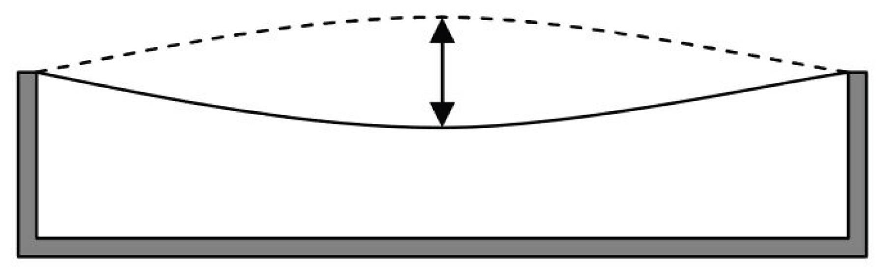
MAs are mass–spring systems. The vibrating mass is a flexible membrane, and the spring is the enclosed air cavity behind the membrane. The air gap can also be filled with a porous absorbent. A basic design of an MA is shown in Figure 1. Acoustic waves that meet the surface of a membrane cause it to oscillate at a frequency determined by its mass and the stiffness of the air spring of the cavity.
The volume in the cavity can be filled with damping material, e.g., fiberglass or other porous materials. The damping will have the following effects. First, the bandwidth of the resonator will be wider. Second, the dissipation of energy in the cavity will be more effective. A simple construction is formed by a cavity with a covering sheet.
The surface impedance W of the resonant system is given as [10]:
W = r + j ω m ρ 0 c 0 cot ( k D ) [ Ns / m 3 ]
In our mass–spring system, the acoustic mass and resistance due to the membrane come into play. The losses resulting in a resistance term (r), a mass term ( ω m ), and a spring term ( ρ 0 c 0 cot ( k D ) ) occur. In the equation, k = 2 π λ is the wavenumber in air, D is the cavity depth, m [ kg / m 2 ] is the acoustic mass per unit area of the panel, ρ 0 is the density of air, ω is the angular frequency, and c 0 is the speed of sound in air. We consider a case without porous absorbent material and with a cavity size much smaller than the acoustic wavelength.
We use the assumption k D 1 , which simplifies the term to cot ( k D ) 1 k D . This leads to the spring behavior. The difference in its argument comes from the medium itself. We now consider a lossless medium and use j k instead of the complex propagation constant Γ.
Systems resonate when the imaginary part of the impedance is 0, so to obtain the resonant frequency, we set the imaginary part of Equation (1) to 0. The resonance frequency f is given by:
f = c 0 2 π ρ 0 m D
By using the constants c 0 = 343 m s and ρ 0 = 1.204 kg m 3 , with the cavity depth D in cm and mass per unit of area m in kg m 2 , this can be further simplified to by [10]:
f 600 m D
In ref. [33], we find the same approximation with d in mm:
f 1900 m D

3.2. Fundamental Acoustic Principles of Micro-Perforated Foil Absorbers

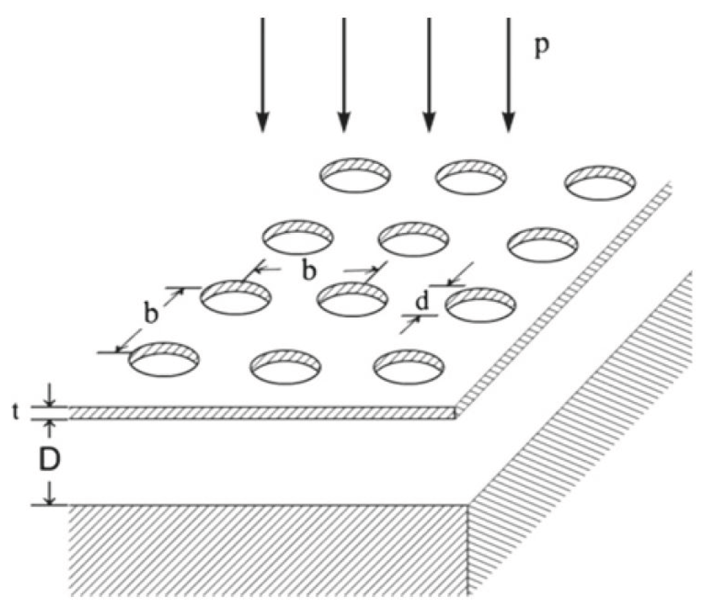
The basic concept of an MPA involves a thin panel with perforations, both sized in the sub-millimetre range. These perforations are designed to match the size of the acoustic boundary layer, ensuring efficient energy dissipation. The key parameters influencing the performance of an MPA include the panel thickness t, the diameter of the perforations d, the spacing between the perforations b, and the depth of the air gap behind the panel D, according to the theory of Maa [6,8] (Figure 2).
The performance is determined by its acoustic impedance, which can be described by the viscous losses within the holes Z hole , the resonances in the air gap Z D , and edge effects Z edge . As sound waves enter the micro-holes, viscous friction causes energy dissipation. This impedance can be modeled as:
Z hole = j ω ρ 0 t 1 2 x j J 1 ( x j ) J 0 ( x j ) 1 [ Ns / m 3 ]
where ω = 2 π f is the angular frequency [rad/s], ρ 0 is the ambient air density [kg/m3], t is the panel thickness [m], J 0 and J 1 are Bessel functions of the first kind of orders 0 and 1, respectively, and x is a dimensionless parameter related to the hole geometry and frequency [34]. The air gap behind the MPA contributes to its overall impedance. The gap acts as a spring, with its impedance given by:
Z D = j Z 0 cot ( k D )
where k is the wave number and Z 0 is the characteristic impedance of air. Corrections for the impedance at the edges of the perforations account for additional mass and resistance:
Z edge = 2 η ω ρ 0 + j 0.85 ω ρ 0 d
where η is the dynamic viscosity of air. The total acoustic impedance of the MPA is a combination of these components:
Z MPA = Z 1 ϵ + Z D
where Z 1 = Z hole + Z edge and ϵ is the perforation ratio. The normalized impedance Z ̲ M P A can be expressed as:
Z ̲ M P A = r + j ω m cot ( k D )
The resulting absorption coefficient ( α ) of the MPA is determined by:
α = 1 | R | 2 = 4 · Re ( Z MPA ) · cos ψ ( 1 + Re ( Z MPA ) · cos ψ ) 2 + ( Im ( Z MPA ) · cos ψ ) 2
where R is the reflection coefficient, and ψ is the angle of incidence of the sound wave.
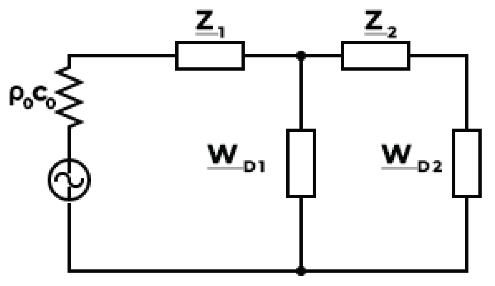
A system with multiple layers n, different geometrical parameters for each layer [ t i , d i , ϵ i ] that are separated by n air gaps with variable or constant depth [ D i ], can be estimated by the approach of solving the equivalent electrical circuit (Figure 3). For simplicity, we rewrite the impedance of the individual perforated panels as Z ̲ 1 to Z ̲ i , the impedance used for modeling the air gap W ̲ D to W D ̲ i .
For a system with two layers ( n = 2 ), the starting point yields to the impedance of the MPA closest to the rigid wall.
W ̲ s e r i a l 1 = Z ̲ 2 + W ̲ D 2
Then, the impedance W ̲ s e r i a l 1 will be in parallel with the impedance W ̲ D 1 resulting from the previous air gap D 1 . It can be written as:
W ̲ p a r a l l e l 1 = W ̲ D 1 W ̲ s e r i a l 1 W ̲ D 1 + W ̲ s e r i a l 1
By adding the impedance of panel 1 Z ̲ 1 to W ̲ p a r a l l e l 1 we obtain the total impedance W ̲ M P A :
W ̲ M P A = W ̲ s e r i a l 2 = Z ̲ 1 + W ̲ p a r a l l e l 1
In order to obtain the most promising set of samples, we conducted a parameter study varying the spacing, hole size, and perforation shape.

3.3. Impedance Tube Setup

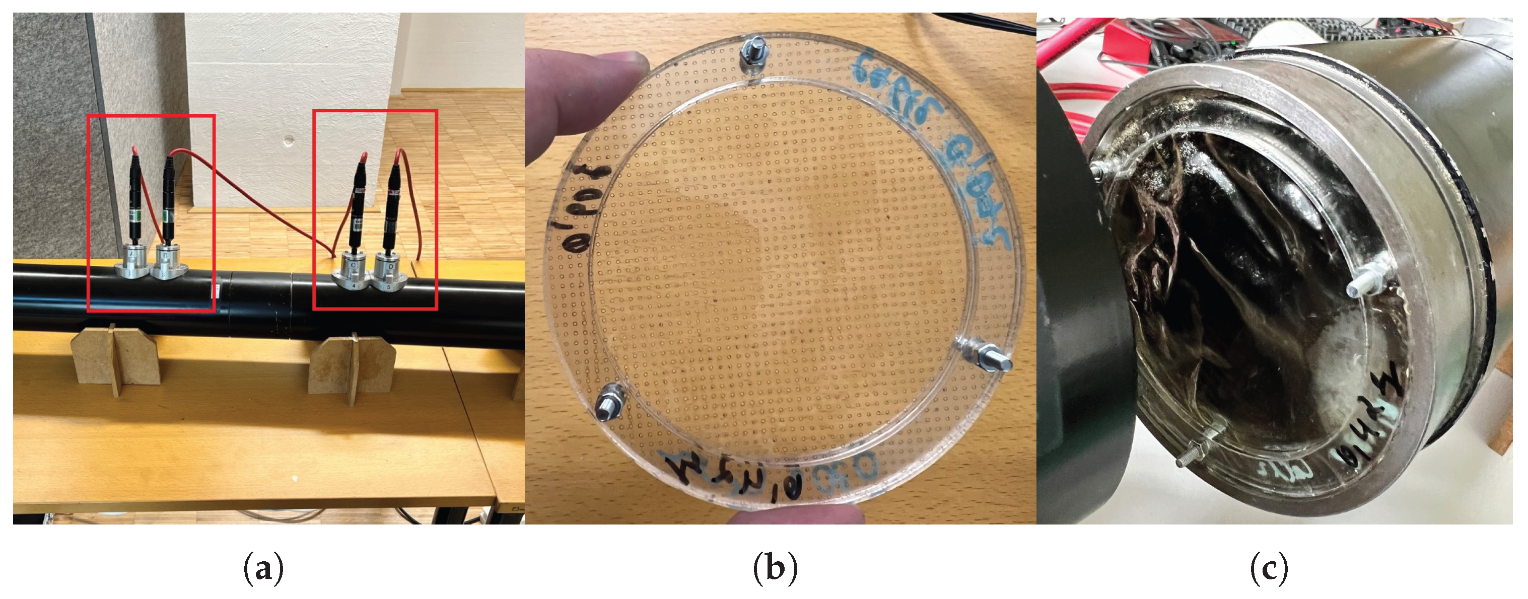
To evaluate the acoustic performance, the absorption coefficient for normal sound incidence was measured in the impedance tube (see Figure 4 for the measurement setup). Architectural sound fields are typically random incidence (diffuse) and include edge or installation effects not captured here. Nevertheless, normal incidence measurements provide a reliable basis for comparing material behavior and identifying trends in absorption performance under controlled conditions.
The impedance tube is a long, narrow tube with speakers at both ends and four microphones positioned along its length to measure the sound pressure at multiple points. This 4-microphone configuration allows accurate estimation of complex transfer functions and surface impedance at the sample plane. The recorded sound pressure signals were then used to determine the material’s absorption coefficient. The acoustic measurements were performed based on EN ISO 10534-2 [35]. While this method provides a comprehensive and accurate characterization of the material’s acoustic properties, it represents a simplified laboratory setup and does not fully reflect diffuse or oblique incidence conditions encountered in real-world architectural environments.
The tube used in this study has an inner diameter of d = 10 cm . This results in a valid frequency range of 85 Hz to 1991 Hz , ensuring plane-wave propagation and avoiding higher-order modes.
A 10-cm-diameter circular sample is prepared for the impedance tube. The holder (Figure 4b) consists of two rigid acrylic rings, laser-cut for precision and reproducibility, with three screws clamping the sample film. This design minimizes interference from the support structure, ensuring accurate acoustic measurements, and is well suited for transmission and reflection tests in the impedance tube. Previous studies have shown that configurations with multiple MPA layers improve absorption across a wide frequency range [36]. For instance, by adding a second absorber at a certain distance from the first one, the absorption for lower frequencies can be improved.

3.4. Materials

The materials used in this study include:
  • Sodium Alginate (SA): Sodium alginate is a naturally occurring polysaccharide used to form hydrogels. Laboratory-grade alginate (SAL: molecular weight 300,000–350,000 g/mol, viscosity 350–550 mPa·s for a 1% solution at 20 °C, pH 5.5–8.0, loss on drying ≤15%) was supplied by Carl Roth GmbH + Co. KG (Karlsruhe, Germany) Standard culinary-grade alginate (SAM), commonly used in molecular gastronomy, was supplied by Würzteufel GmbH (Empfingen, Germany). Both alginates were dissolved in distilled water to prepare solutions for foil formation.
  • Distilled Water (H2O): Distilled water (CAS No. 7732-18-5, molecular weight 18.02 g/mol, boiling point 100 °C) was used as the solvent for preparing alginate solutions. Its neutral pH and absence of ions ensure uniform dissolution of sodium alginate. Tap water was avoided to prevent unintended cross-linking or altered gelling due to the presence of calcium, magnesium ions, or variable pH.
  • Glycerin (Glycerol ≥ 99.5%) (Gl): Glycerin (CAS No. 56-81-5, molecular weight 92.09 g/mol, boiling point 182 °C/20 mmHg, purity ≥ 99.5%) was used as a plasticizer to enhance the flexible properties of the alginate foils. It is a colorless, odorless, and viscous liquid of high purity, supplied by Carl Roth GmbH + Co. KG (Karlsruhe, Germany).
  • Calcium Chloride Di-hydrate (≥99%, p.a., ACS) (CaCl2): Calcium chloride dihydrate (CAS No. 10035-04-8, molecular weight 147.02 g/mol, density 1.85 g/cm3, purity ≥ 99%, p.a., ACS) was supplied by Carl Roth GmbH + Co. KG (Karlsruhe, Germany), DE. It was used as a cross-linking agent for sodium alginate due to its high purity and compliance with analytical and ACS standards, ensuring reproducible gelation behavior.
  • Calcium Carbonate (≥98.5%, Ph. Eur., USP, granulated) (CaCO3): Calcium carbonate (CAS No. 471-34-1, molecular weight 100.09 g/mol, density 2.93 g/cm3, purity ≥ 98.5%, Ph. Eur., USP, granulated) was used as a cross-linking agent and to generate controlled perforations in the alginate foils. It was supplied by Carl Roth GmbH + Co. KG (Karlsruhe, Germany), ensuring high purity and consistency in the formation process.
  • Hydrochloric Acid (HCl): Commonly used for pH adjustment during the formulation process. In combination with calcium carbonate (CaCO3), HCl lowers the pH, promoting the gradual release of carbon dioxide (CO2) and calcium ions (Ca2+ ions) necessary for bubble creation and controlled gelation. It is a strong, corrosive acid with a pH around 1.

3.5. Material Formulation Process

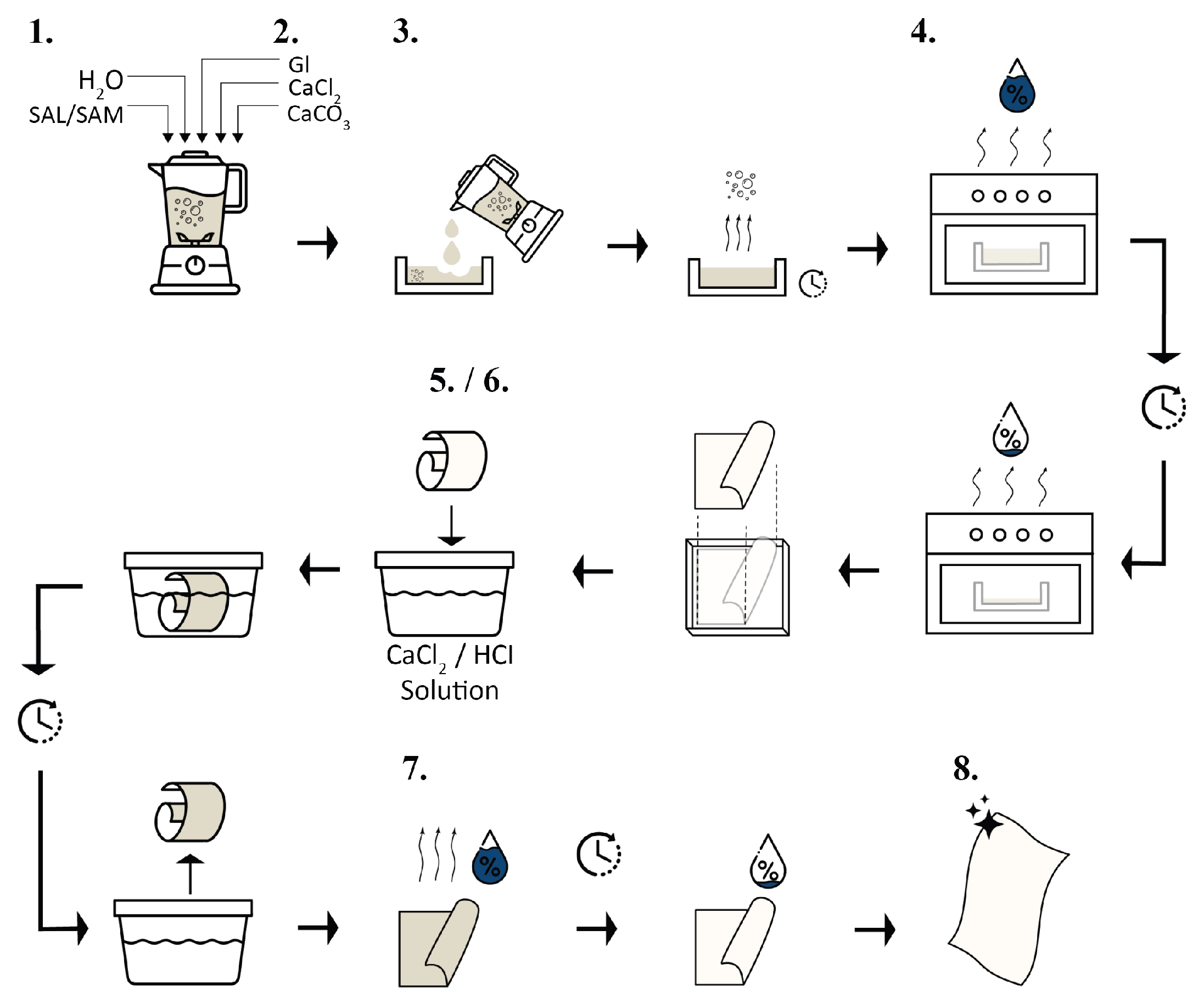
The formulation of alginate foils follows the numerical step-by-step procedure outlined below (Figure 5):
1.
Solution Preparation: SAL or SAM powder is dissolved in H2O to create a homogeneous sodium alginate solution (AL). The alginate concentration is adjusted to achieve a viscosity suitable for pouring.
2.
Additive Integration: Gl and CaCl2/CaCO3 are added to the alginate solution. Different concentrations of CaCl2/CaCO3 were tested to achieve an optimal crosslinking degree that balances stability without compromising the film’s transparency.
3.
Casting: The viscous mixture was poured into various molds. Higher fill levels resulted in thicker films due to the greater amount of solid chemicals remaining after water evaporation.
4.
First Drying: The casted molds are dried under controlled temperature to produce solid, bendable films. The drying process is carefully optimized: slower drying rates help prevent cracking and ensure consistent film quality.
5.
External Cross-link: For Experiments 1 and 3, the films have been immersed in a calcium chloride (CaCl2) bath, which strengthens the film surface by adding additional Ca2+ ions. This external crosslinking forms a dense outer layer that significantly improves water resistance and mechanical stability by limiting swelling and dissolution.
6.
pH Adjustment: For Experiment 2 with CaCO3, HCl is used to adjust the pH, enabling optimal conditions for cross-linking. The gradual release of Ca2+ ions from the slowly soluble CaCO3 in the acidified environment ensures controlled, homogeneous internal gelation within the alginate matrix.
7.
Second Drying: After the CaCl2 or HCl solution, the foils were set aside and dried at room temperature for 24 h.
8.
Further Processing: The final foil was then perforated using an Epilog Fusion M2 laser cutter (Epilog Laser, Golden, CO, USA) and prepared for subsequent acoustic measurements.
A total of three experiments (E1E3) were conducted to develop thin alginate-based foils with tunable material properties. The experimental program included variations in material composition, cross-linking strategies, and fabrication scale. For each experiment, the number of specimens, the investigated parameters, and the measured properties are summarized in Table 1. In this study, the term ‘sample’ refers to a specific alginate formulation (material variant), whereas ‘specimen’ denotes an individual film produced from that formulation and used for acoustic or mechanical testing. Multiple specimens were prepared for each sample to ensure reproducibility.
  • Experiment 1 (E1) investigated the influence of different CaCl2 concentrations on internal ionic cross-linking and film formation [37,38], using sodium alginate powder (SAL) commonly used in the medical field.
  • Experiment 2 (E2) examined pore formation through a CaCO3–HCl reaction coupled with external cross-linking.
  • Experiment 3 (E3) focused on upscaling the process from using low-cost sodium alginate (SAM) in a workshop environment and included external CaCl2 cross-linking to achieve water resistance.
Each experiment is described in detail below, outlining the methods and results.

3.5.1. Experiment 1 (E1)

A total of five samples were prepared—with each sample resulting in three specimens—using identical mixing and drying procedures, with the only variation being a stepwise increase of 0.036% CaCl2 in each subsequent sample [39,40,41,42]. Specimens from sample E1_CaCl2_1 were used exclusively for acoustic measurements, as this formulation exhibited the best foil-forming performance, as documented in this section.
The alginate solution (AL) was prepared by dissolving 2 g (2 wt%) of SAL in 93 g H2O and stirring to complete dissolution. For stirring, the laboratory mixer was used at a speed starting from 5 rpm and continuously increasing to 150 rpm. After 15 min of stirring, a viscous yellow solution was produced. For the CaCl2 solution, the desired amount of CaCl2 was mixed together with the corresponding amount of H2O separately (Table 2). The speed of mixing was reduced from 150 rpm to 30 rpm and the CaCl2 solution was slowly dropped to the AL. The crosslink occured immediately, recognizable through the gelatinization of the AL [43]. In order to provide a thorough mixing, the residues on the stirrer were removed carefully with a spatula. The stirring speed was increased to 200 rpm and maintained for at least 20 min, ensuring that all CaCl2 lumps were fully dissolved. The sample mixture was then poured into three round Petri dishes, each 10 cm in diameter and 1.5 cm in height. The dishes were placed in a laboratory cabinet with a built-in exhaust blower at at 50% relative humidity and left to dry for 24 h.
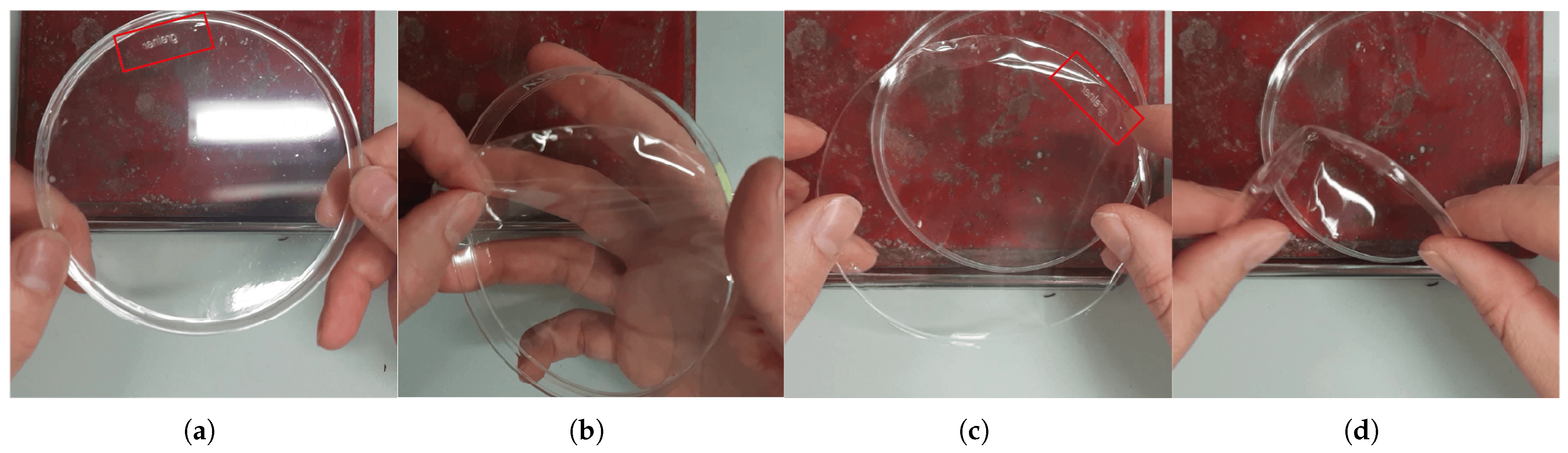
After drying, sample E1_CaCl2_1 formed a foil approximately 0.16 mm thick. The film exhibited qualitatively assessed properties of being clear, transparent, and bendable, yet noticeably brittle. It replicated the geometry of the Petri dish with high fidelity, including fine surface details such as the engraved brand name, as shown in Figure 6a,c.
Four additional specimens were produced with progressively increasing CaCl2 concentrations, which caused the resulting films to become increasingly brittle and less flexible. Among all formulations, the variant containing 0.036 wt% CaCl2 provided the best balance between film-forming ability and mechanical flexibility. These findings indicate that a CaCl2 concentration of 0.036 wt% achieves effective cross-linking with 2 wt% sodium alginate, and that a gentle drying process further supports the formation of a clear, bendable, foil-like material.
To evaluate the film’s solubility in water and examine whether the material could reform into a continuous foil after rewetting, an additional test was performed. The dried alginate films were first removed from their moulds, then placed back into the Petri dishes, where 20 g of H2O was added. Upon contact with water, the films dissolved immediately. This rapid dissolution is attributed to the low degree of ionic cross-linking within the material: water molecules penetrate the polymer network, disrupt the weak ionic interactions between alginate chains and Ca2+ ions, and thereby break the cross-links, allowing the polymer chains to disperse into solution [44].
After another 24 h of drying, the alginate solution reformed into a thinner film due to partial dissolution. Alginate is soluble in water to a certain extent, particularly if the cross-linking is weak or incomplete (e.g., insufficient calcium ions in calcium alginate gels). Water can dissolve parts of the alginate film, reducing its thickness as some material diffuses into the surrounding water. In E3, an external crosslinking approach was tested to achieve water resistance. E1 focused on finding the ideal CaCl2 concentration in the formulation to optimize the cross-linking density and thereby improve the stability of the films.

3.5.2. Experiment 2 (E2)

This experiment focuses on additives that induce chemical reactions to create bubbles, resulting in the desired perforation of the sample, used exclusively for exploratory acoustic measurements discussed in a later section.
SA solution (2 wt%) was prepared by dissolving the SAL powder in a Gl–H2O liquid and stirring it for 15–20 min until all particles dissolved. The desired amount of CaCO3 was added, mixed again, and poured into customized Petri dishes 11 cm in diameter and 0.5 cm in height. The filled dishes were then dried at 60 °C for 24 h using a drying oven. The Petri dishes were designed to match the size of the impedance tube used for measuring sound absorption. Two additional samples with varying amounts of CaCO3 were also prepared (Table 3).
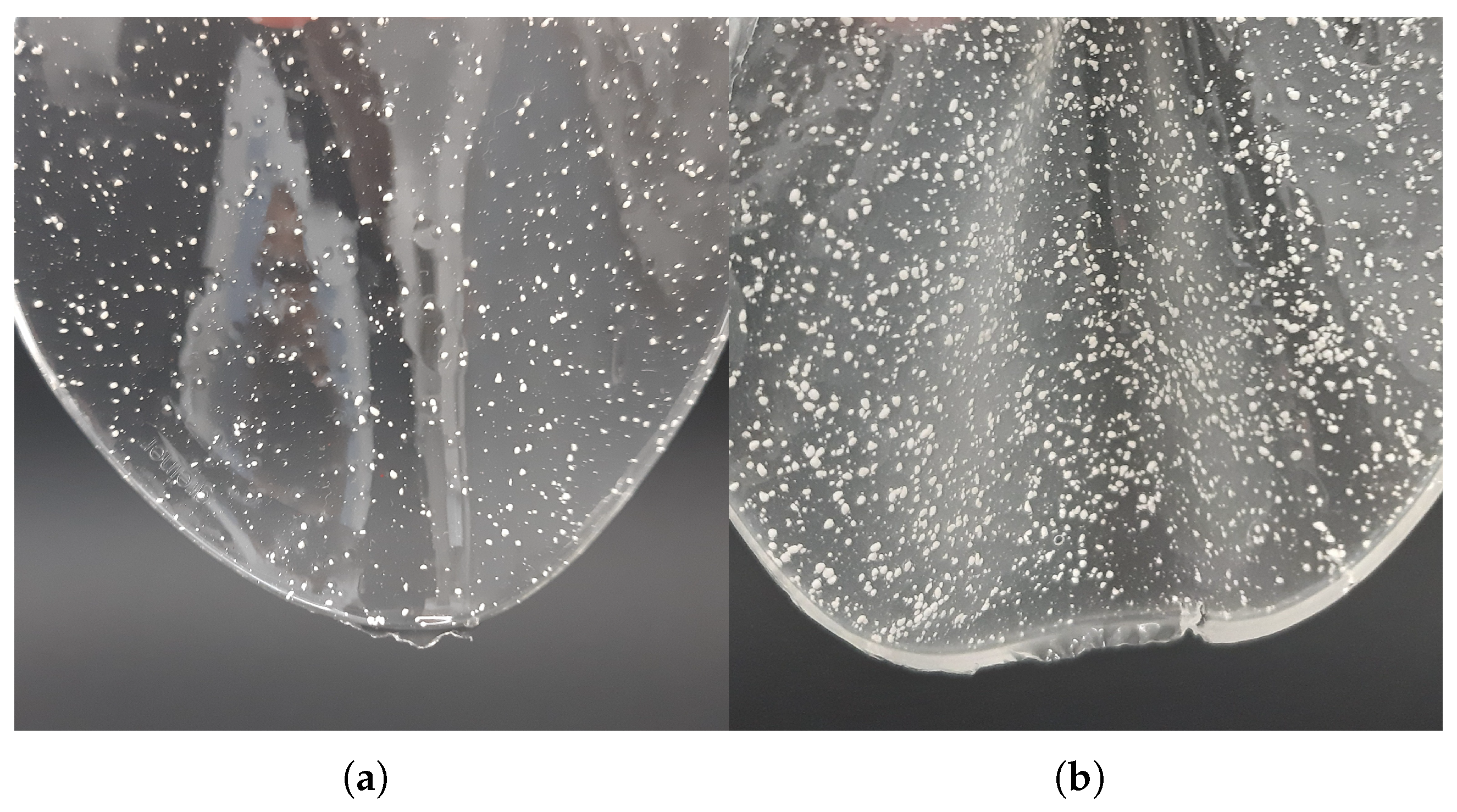
Figure 7 shows two samples prior to the HCl bath, representing the lowest and highest CaCO3 content, respectively. After drying, the films were immersed in a hydrochloric acid (HCl) bath for 24 h to induce two simultaneous chemical reactions with the release of CO2 and Ca2+ ions. This process creates bubbles within the film while simultaneously promoting cross-linking. The results demonstrate that both the uniformity of bubble distribution and the quantity of CO2 released correlate with the concentration of CaCO3 present in the mixture.
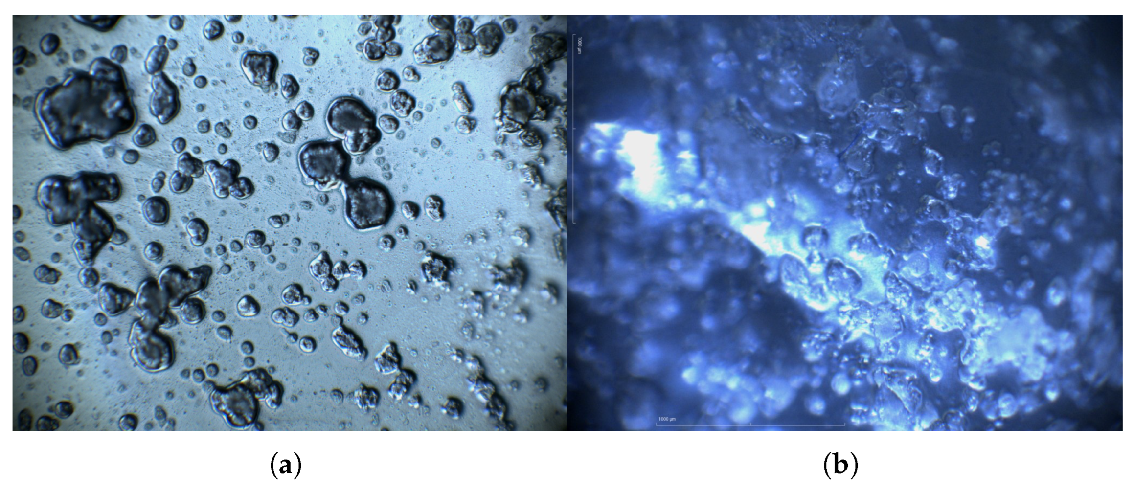
Figure 8 presents optical microscope images of alginate films after HCl treatment, highlighting the influence of CaCO3 content on pore formation. Image (a) depicts the sample with the lowest CaCO3 concentration, characterized by sparse and relatively small gas bubbles resulting from limited CO2 generation. Image (b) shows the sample with the highest CaCO3 content, displaying a denser and more interconnected network due to more vigorous gas evolution.
These observations demonstrate the effect of CaCO3 concentration on the morphology and pore development within the alginate matrix. All air bubbles remain enclosed within the foil. From an acoustic perspective, this does not result in the desired outcome, namely a foil with open porosity. After drying, the foil became water-resistant due to the cross-linking process that occurred when the foil was placed in the HCl bath.

3.5.3. Experiment 3 (E3)

The first two experiments were conducted under controlled laboratory conditions using highly sensitive sodium alginate powder (SAL). In contrast, E3 focuses on low-cost sodium alginate powder (SAM), upscaling the formula from E1 and balancing the Gl content after acknowledging the high flexibility of E2 sample results. From E1, we retained the amount of CaCl2 in the alginate solution. Additionally, we continued to use the CO2 bath (0.5 M CaCl2, in Table 4) for final cross-linking to ensure water resistance.
Two sample mixtures with identical formulation properties were produced, with three to five specimens accordingly (Table 4). Specimens from sample E3_GlCaCl2_1 were used exclusively for acoustic measurements, while E3_GlCaCl2_2 were used exclusively for tensile testing, as documented subsequently in this paper.
AL was prepared by dissolving SAM in a mixture of H2O and Gl, followed by continuous stirring for 15–20 min until fully dissolved. In parallel, the desired amount of CaCl2 was dissolved in an H2O–Gl solution. This CaCl2 solution was then combined with the AL. The resulting sample mixtures were cast into three round Petri dishes (sample E3_GlCaCl2_1) and one rectangular mold (sample E3_GlCaCl2_2). The specimens were placed for drying at 35 °C in a laboratory drying oven for 24 h.
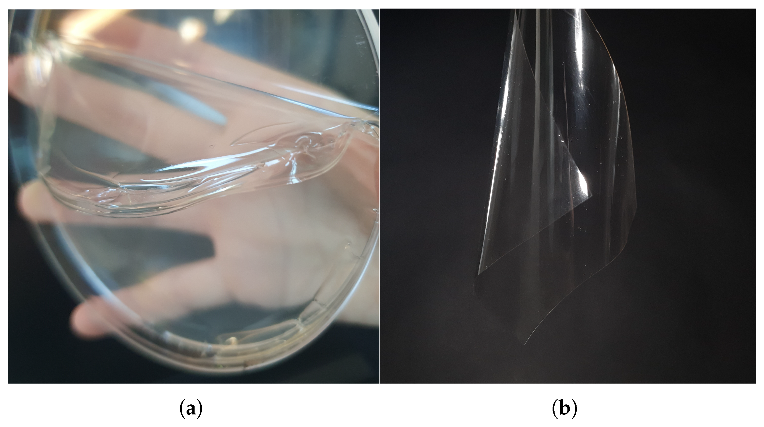
On the following day, the solidified foils were immersed in a highly concentrated CaCl2 solution (0.5 M) to achieve external ionic cross-linking of the alginate matrix. After cross-linking, the films were removed from the solution and air-dried under ambient conditions for another 24 h. After the external cross-link and final drying process, the alginate film presented a transparent and uniform surface with bendable characteristics, as shown in Figure 9a,b. The rectangular film measured 24.5 × 23 cm, with a thickness ranging from 0.25 to 0.98 mm, while the circular films had a diameter of 11.5 cm.

4. Results and Discussion

To assess the feasibility of using alginate for sound absorption, we characterized selected prototypes by measuring their sound absorption and, for a separate subset of samples, their mechanical properties (strength and elongation). Each experiment is documented in detail in the respective sections of the manuscript.

4.1. Analysis of Design Parameters

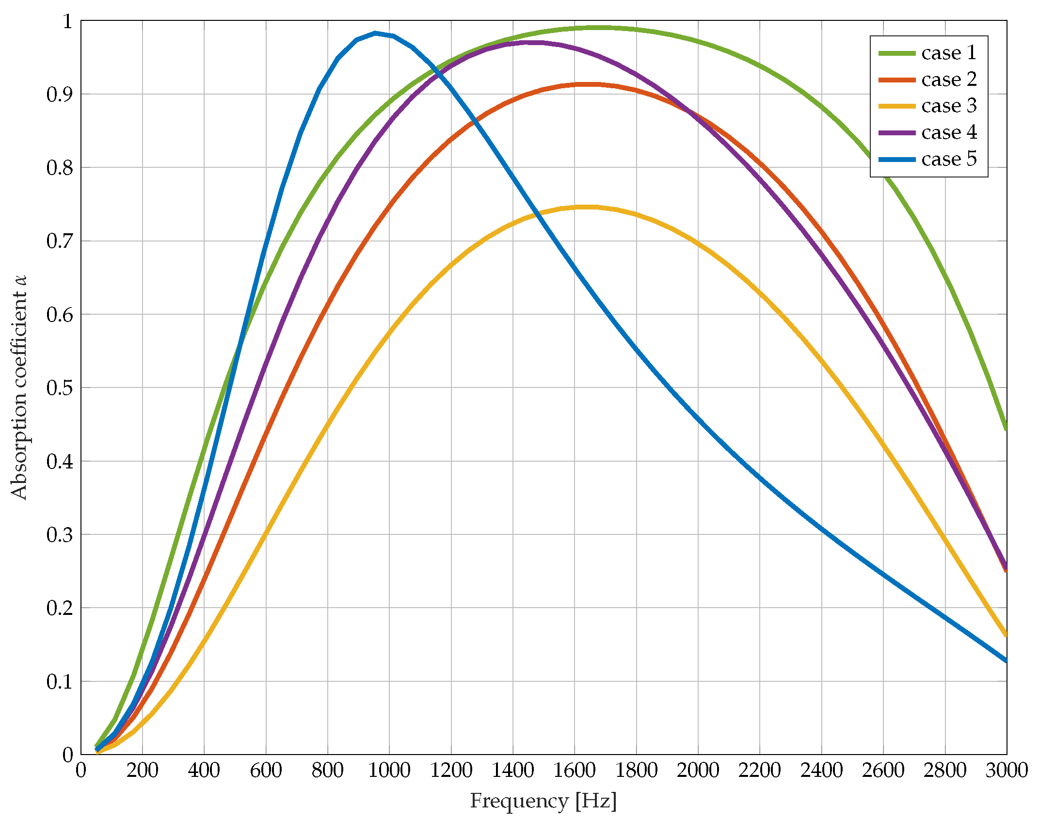
To provide insights into the effect of MPA, we present a comparative analysis of key design parameters through Table 5 and Figure 10. In order to obtain broad band absorption, the perforation diameter has to be reduced to obtain sufficient acoustic resistance and low reactance. The maximum perforation ratio is 20 % , confirming the basic assumptions of Maa’s theory [15]. By decreasing the perforation diameter to d 100 μ m , we broaden the absorption bandwidth significantly.
Figure 10 shows the absorption coefficient for those cases. We notice the highest absorption value α 0.4 for the frequency range 400 Hz to 3 kHz for case 1. In accordance with Maa’s theory, an air gap between the microperforated film and the rigid backing is required to enable resonance and effective energy dissipation. Based on our previous parameter study, the cavity depth was set to D = 5 cm.

4.2. Acoustic Measurements for E1

For the subsequent acoustic measurements for E1, three measurable specimens ( n = 3 ) from sample E1_CaCl2_1 (Table 2) were used due to their appropriate durability. As controlled perforation using chemical reactions was unsuccessful, a laser cutter was employed to create small holes in the solid alginate films.
The laser cutter offered sufficient control to create the desired perforations after careful adjustments were made to the speed and power of the laser to optimize the results for each sample. These adjustments included using lower power, very slow speed, and higher frequency. Precise laser focus was ensured using auto-focus features, and the air assist feature was utilized. Although alginate films are not highly flammable, the excessive heat of the laser cutter can cause damage or slight burning to the material.
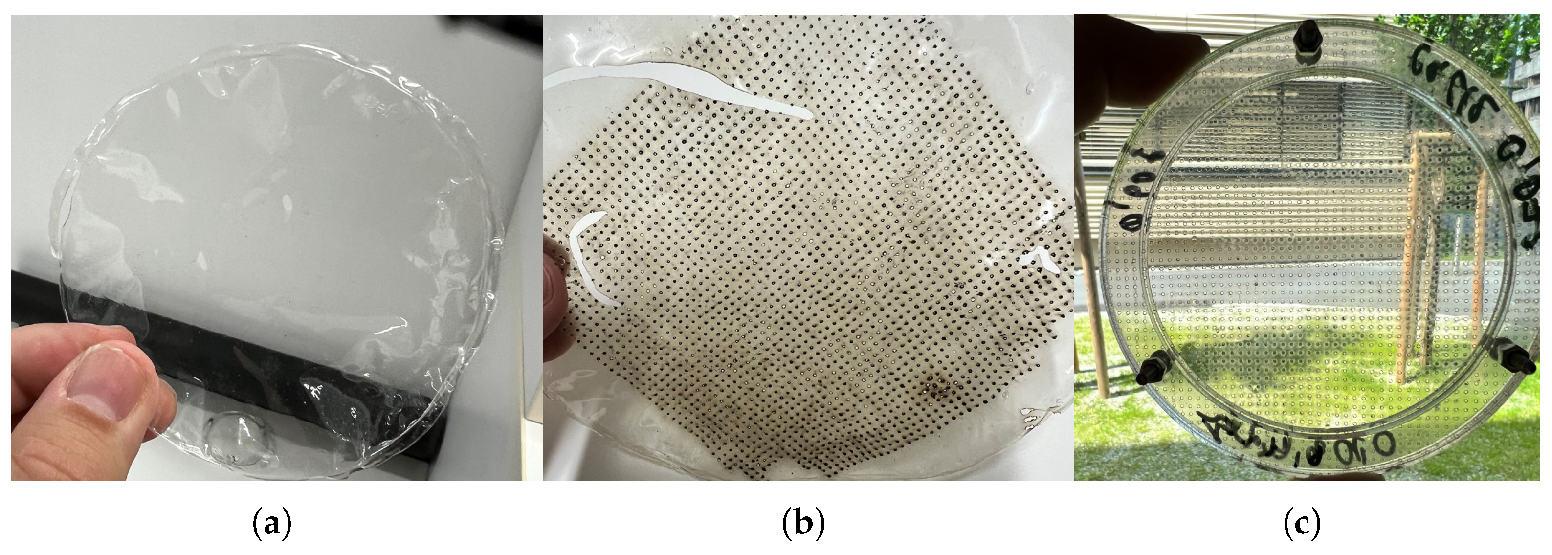
According to the theory of micro-perforated films, Figure 11 presents (a) the clear foil sample, which (b) was perforated using a laser cutter (c) and put into the frame for further measurements in the impedance tube. The perforation pattern follows a favorable calculation of the design parameters for desired broadband absorption. As a drawback of the laser cutter perforation technique, the film is not completely transparent anymore, caused by the burned edges.
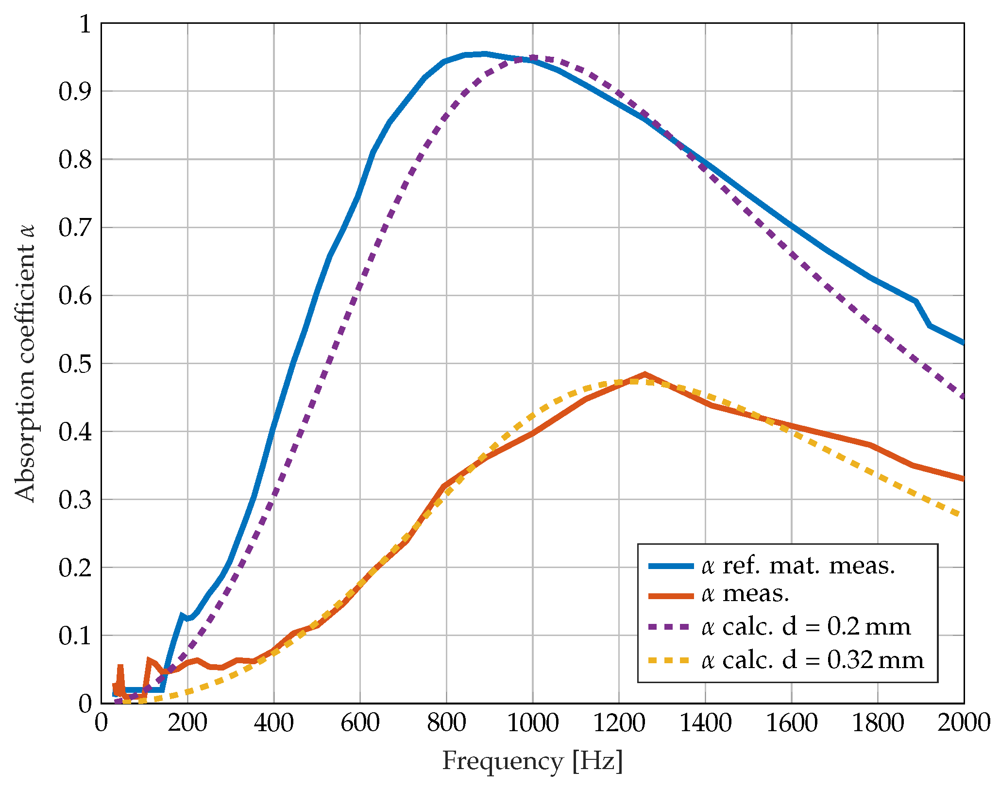
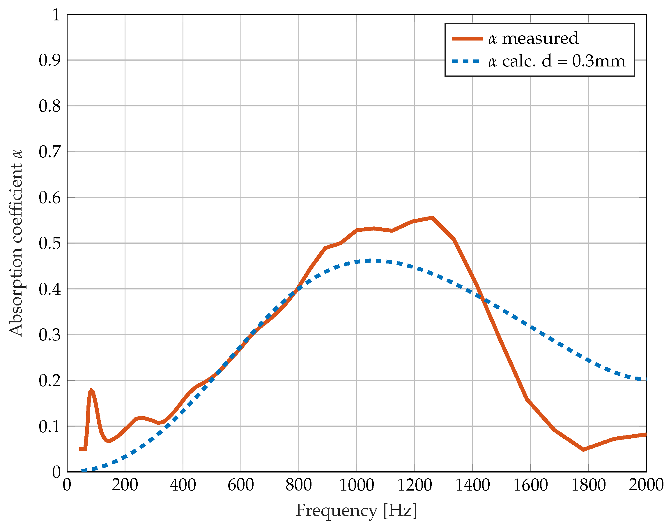
Figure 12 shows the measured absorption coefficient for one sample perforated with the laser cutter and includes a commercially available reference MPA film measured under identical impedance tube conditions. The design parameters for the perforation pattern as well as the reference film are b = 2 mm, d = 0.2 mm. Although the sample shows MPA characteristics, the measured results for the alginate sample differ significantly from the measured reference MPA film. We notice a broad absorption behavior, but with a lower peak found at f 1 = 1260 Hz and α = 0.49 .
This can be attributed to variations in hole size d during laser perforation. The effective hole size seems to be above the desired 0.2 mm. One can observe that an assumed effective hole size of d = 0.32 mm fits the measured result more accurately. As a result of this increased hole size, the viscous losses in the perforations decrease, which lowers the absorption amplitude. In addition, the increased hole size reduces the acoustic mass of the perforations, which can shift the resonance towards higher frequencies compared to the theoretical design. Ensuring a perfectly flat film surface during cutting and precise laser focus adjustment are crucial factors to improve perforation accuracy.
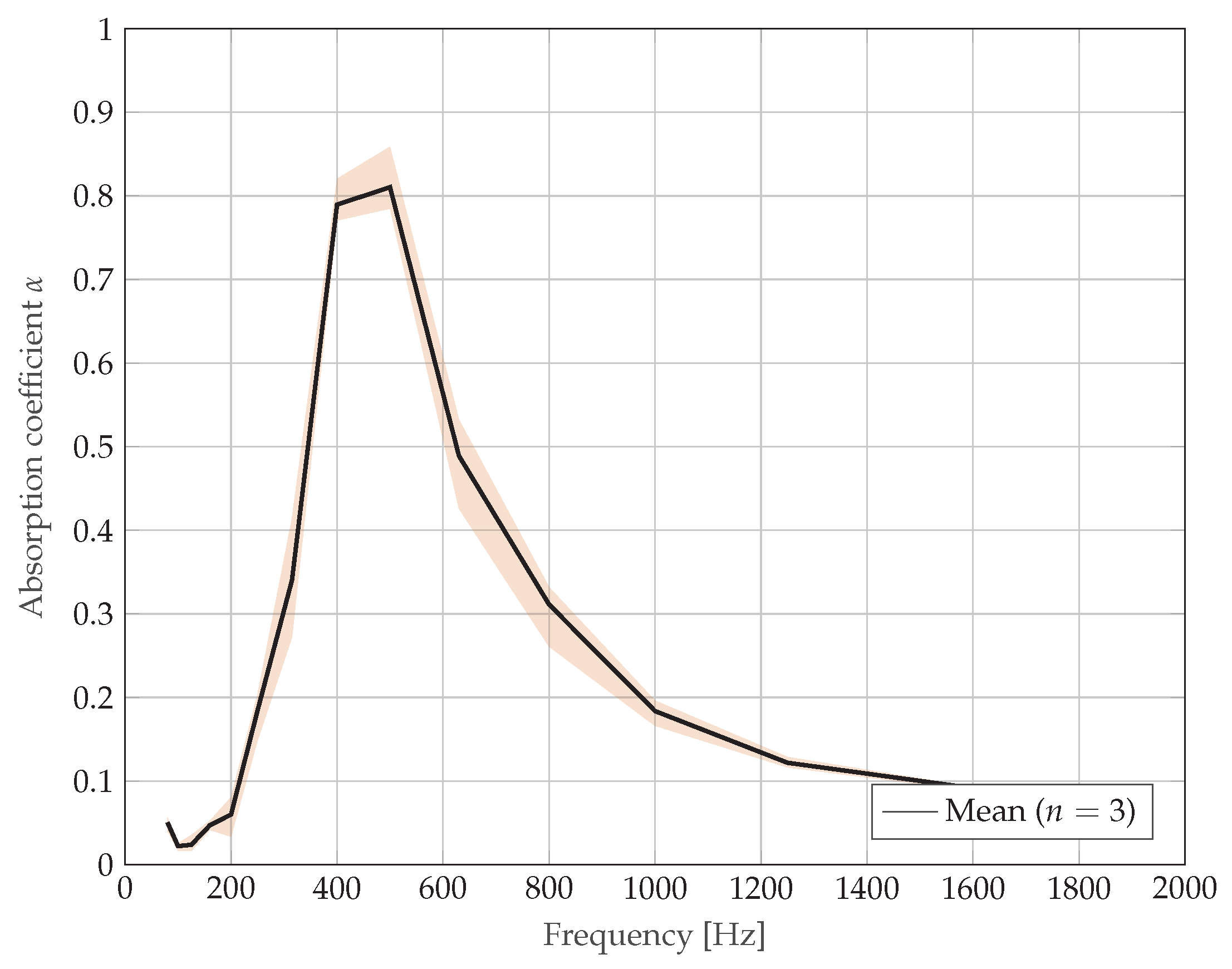
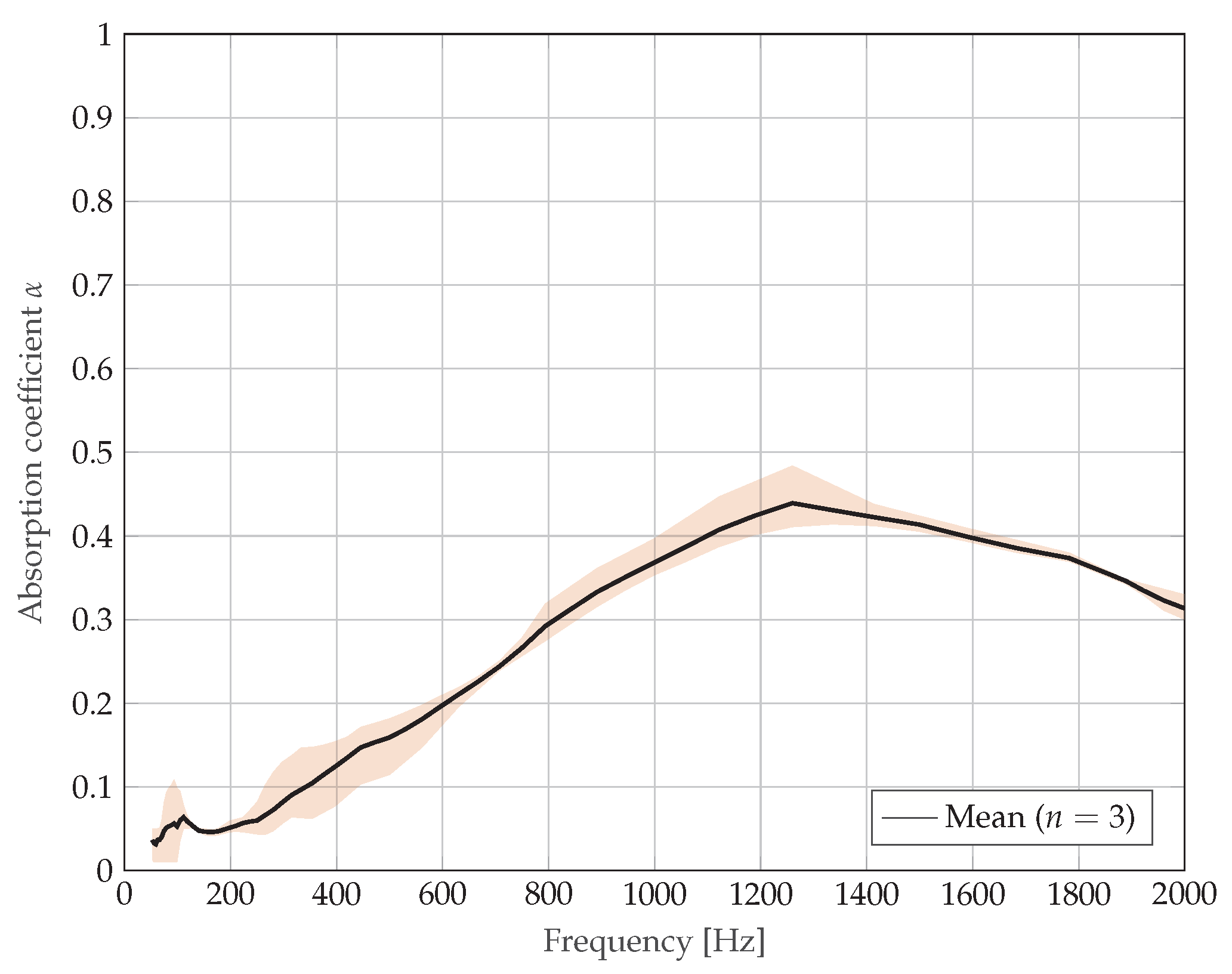
Figure 13 summarizes the E1 acoustic measurements ( n = 3 ). The mean curve is shown together with a min–max envelope to indicate variability. Despite identical manufacturing conditions, the resulting foil thickness varies between specimens, with mean thickness values in the range t = 100 μ m to 160 μ m , which contributes to the observed spread.

4.3. Acoustic Observations for E2

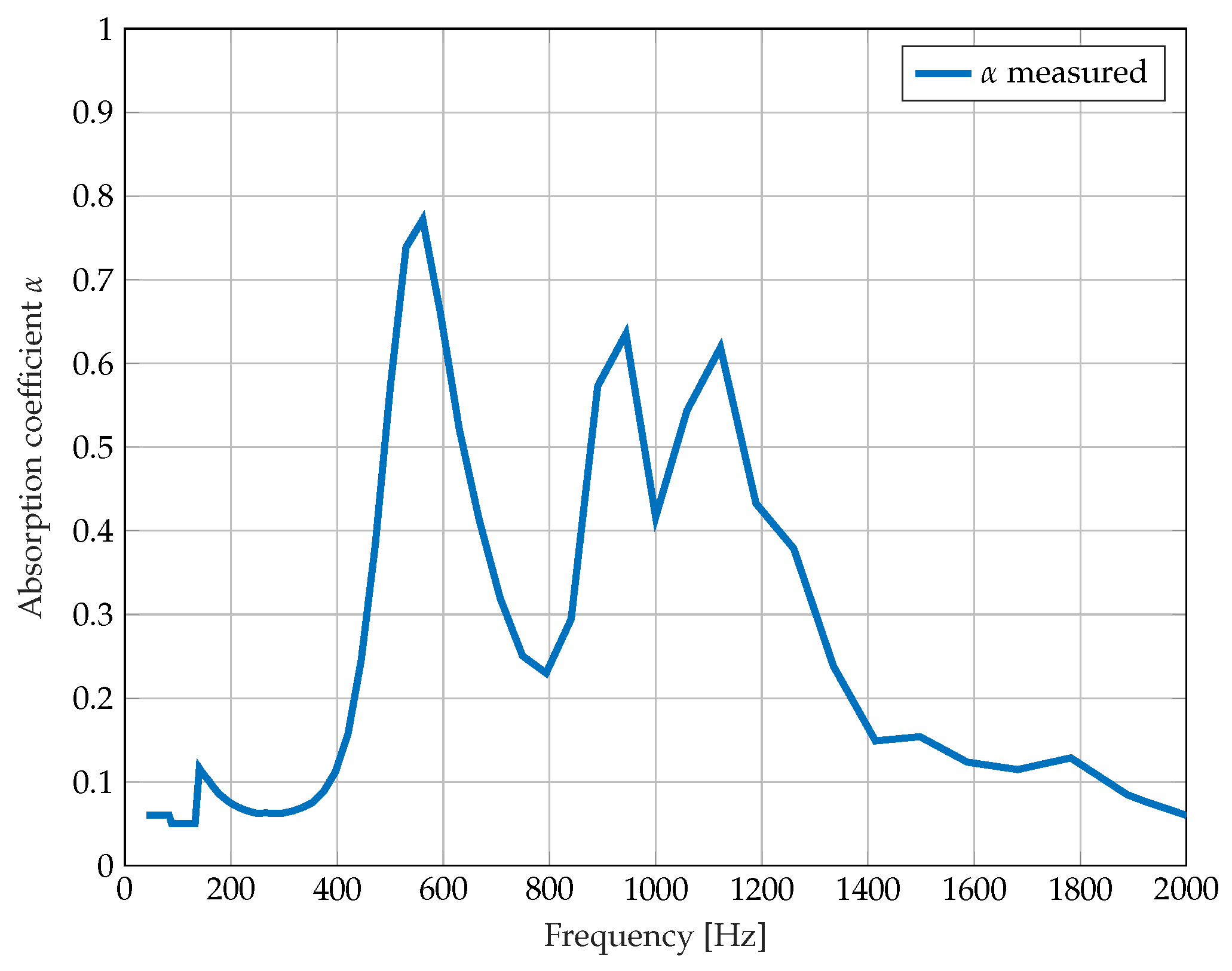
Specimens from sample E2_CaCO3_1 (Table 3) were used for measurements. Due to limited mechanical stability, only a single specimen was suitable for acoustic measurement; therefore, the E2 results are presented as preliminary, exploratory observations and are not intended as statistically representative material characterization. Figure 14 shows the measured absorption coefficient. We notice three narrow peaks occurring at f 1 = 561 Hz, f 2 = 943 Hz, and f 3 = 1122 Hz. The sample film shows characteristics of an MA. The measured resonance frequencies are compared to calculated values. The resonance frequency f is given by:
f = c 0 2 π ρ 0 m D
By using the constants c 0 = 343 m s and ρ 0 = 1.204 kg m 3 , with the gap depth D in cm and mass per unit of area m in kg m 2 , this can be further simplified.
Using Equation (3) the theoretical model provides a basis for interpreting the experimentally observed peaks. The calculated resonance frequency f 1 = 565 Hz lies slightly above the measured f 1 = 561 Hz. The third peak, measured at f 3 = 1122 Hz, appears at twice the fundamental frequency. For the peak f 2 = 943 Hz, we repeat the thought experiment of the previous measurement and assume Helmholtz behavior due to air bubbles. We use the peak at f 2 = 943 Hz to calculate the perforation ratio ϵ = 1.72 %.
Uneven air bubbles prevent the determination of the perforation ratio, though the result may be reasonable. Also, the corresponding thickness inhomogeneities could lead to the peak on f 2 . The sample does not show MPA behavior as the pores in the film do not appear to be open. The acoustic measurement revealed limited performance of the sample; therefore, further measurements were not pursued. As a result, no statistical evaluation was conducted. Quantitative and repeatable acoustic characterization in this study is therefore based on the E1 and E3 routes, which provided mechanically stable specimens suitable for repeated measurements.

4.4. Acoustic Measurements for E3

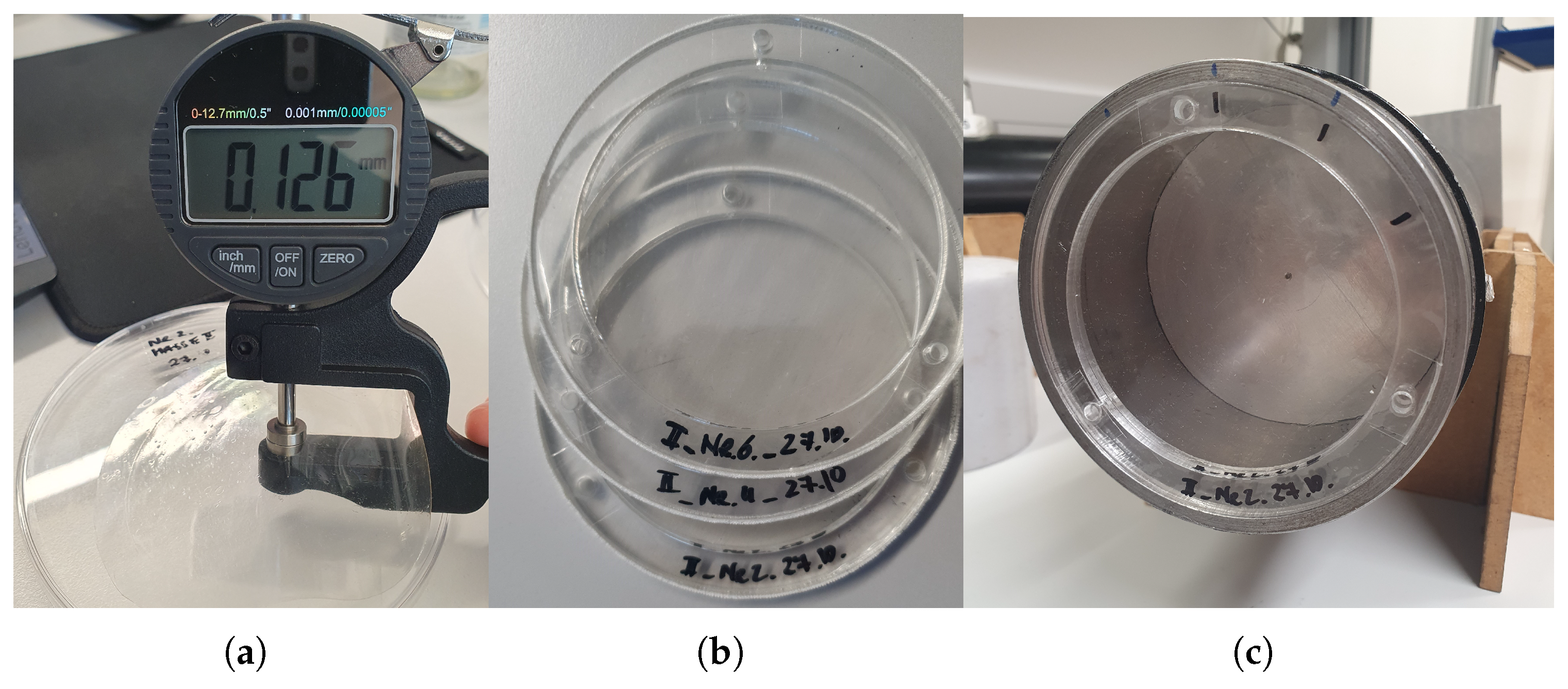
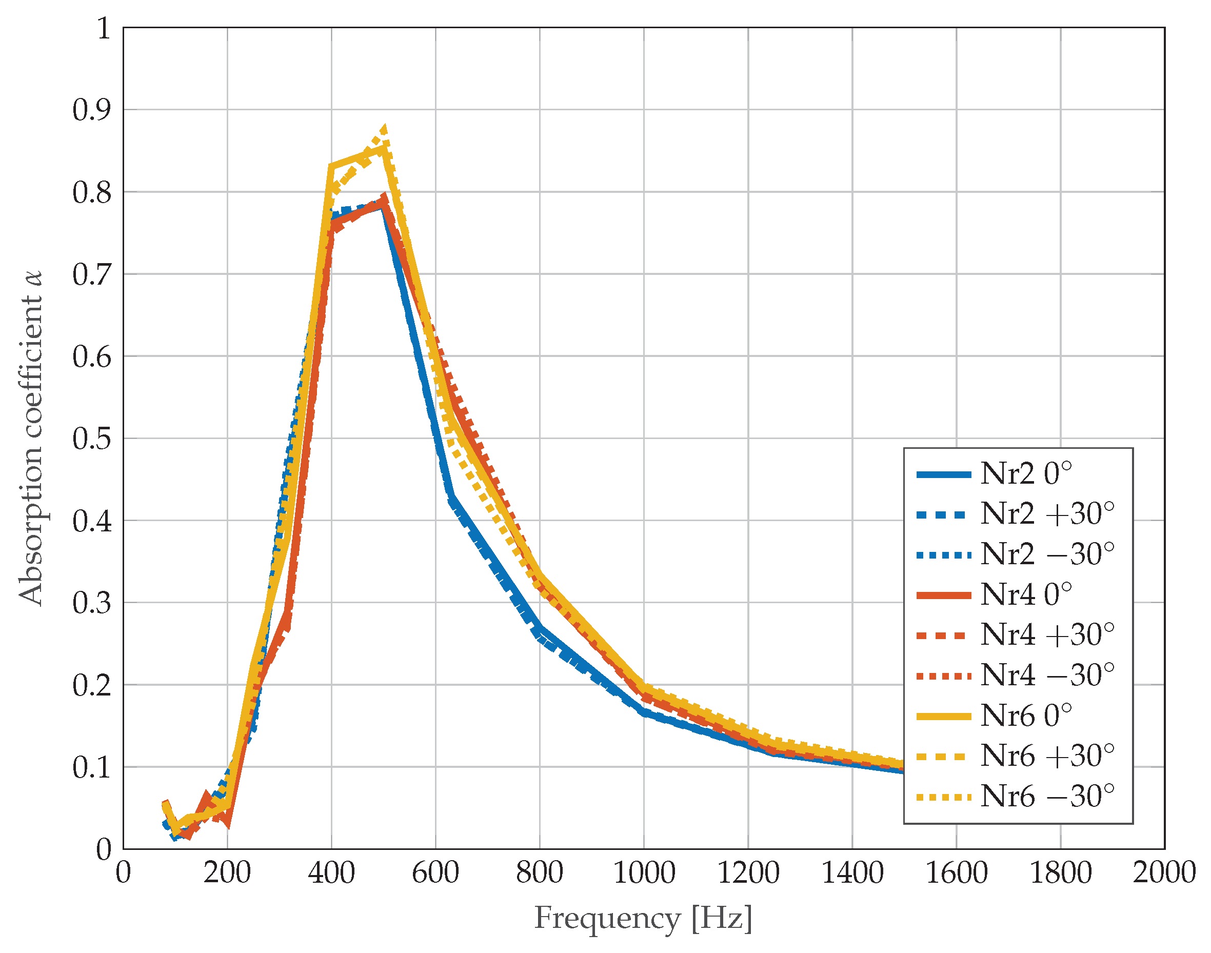
For the acoustic measurements for E3, three specimens ( n = 3 ) from sample E3_GlCaCl2_1 (Table 4) were investigated using non-perforated alginate foils. Figure 15 shows a representative E3 film measured with a digital thickness gauge (a), all three specimens prepared in the acrylic rings for the acoustic measurement setup (b), and one specimen in the impedance tube. All three specimens were measured with an air cavity depth of D = 52 mm . To evaluate mounting sensitivity and repeatability, each specimen was measured repeatedly after rotating the sample by 0 ° and ± 30 ° .
Figure 16 and Figure 17 summarize all measurements. The resulting curves consistently exhibit membrane absorber characteristics (narrow-band resonant absorption) rather than MPA behavior, which is expected since the films are continuous and not micro-perforated. The observed spread between curves can be attributed to specimen-to-specimen variability despite identical manufacturing conditions, in particular thickness variations (mean thickness t = 100 145 μ m ) and local inhomogeneities, as well as mounting and rotation sensitivity.
From an application perspective, this membrane-type behavior is a valuable result: thin, bio-based foils combined with a rear air cavity can act as tuned resonant absorbers, enabling targeted absorption with low construction depth. This is particularly relevant for integration behind architectural linings or panels in retrofit situations where space is limited.

4.5. Double-Layer Acoustic Observations

In addition to single-layer measurements, a preliminary proof-of-concept double-layer configuration was investigated to explore the potential of stacked alginate MPAs to broaden and enhance absorption. The absorption coefficient of a double-layer configuration was measured and then compared to the estimated absorption coefficient according to the theory. Due to their build quality, two specimens from sample E1_CaCl2_1 (Table 2) were combined to investigate double-layer behavior.
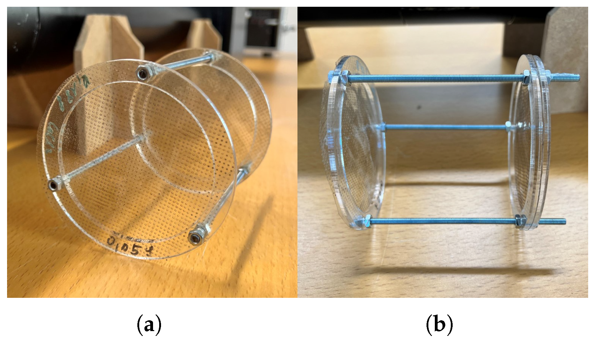
Self-fabricated rings were developed to serve as structural frames and are connected by four evenly spaced threaded rods, which maintain parallel alignment and a fixed spacing between the rings. The distance between the two layers could be adjusted variably, under light tension and in a well-defined position. Figure 18 shows the frame with two layers of the alginate film. A distance D 1 = 6 cm separates the two layers of alginate. The back layer (from E1) is assumed to be close to a rigid wall (b) with D 2 = 1 cm. D 2 was a simulated air gap, implemented with the measurement software CATS8.
Figure 19 shows the measured absorption coefficient α for alginate films from E1. The configuration exhibits the desired MPA characteristics with α 0.4 from 800 to 1408 Hz. The measured absorption is compared to a simulated double-layer configuration. Compared to the simulation, the absorption peak is slightly reduced, and α decreases faster above 1400 Hz, likely due to measurement setup effects, frame connections, or slight inaccuracies in the perforation pattern affecting the interaction of b and d. The acoustic measurement showed that the absorption coefficient at frequencies above f = 1400 Hz did not meet the expected performance. On this basis, no further experiments were undertaken. Since the resulting dataset comprised only a single measurement, statistical evaluation was not possible and was therefore omitted. In the frequency range between f = 800   Hz and f = 1400 Hz, the double-layer absorption is higher than that of the single layer.

4.6. Tensile Measurements

Tensile tests were conducted to determine the maximum load-bearing capacity of the alginate foils and to assess their mechanical behavior under stress. Such testing is essential for advancing the material’s development, particularly to ensure its suitability for competing with conventional absorption foils and for its structural integration. The tensile tests were performed in accordance with the general principles of ISO 527, adapted for thin, highly flexible alginate foils.
Uniaxial tensile tests were carried out using a ZPM (Z3/Z5) tensile testing machine (Gripsoft GmbH, Nürnberg, Germany), whose electronic components comply with EMC requirements according to DIN EN 61000-4-2 (VDE 0847-4-2), as specified in the device documentation [45]. Specimens were tested at a constant crosshead speed of 20 mm/min with an initial gauge length of 200 mm. A 3 kN load cell (maximum force 2980 N; sensitivity 3.216 mV/V) was used, and force–displacement data were recorded using THSSD Windows 2026 software (Win64).
Foil thickness was measured at three points along the gauge length using a digital thickness gauge (0.01 mm resolution), and the mean value was used for stress calculations. Samples were clamped using rubber-coated hydraulic jaws, with clamping pressure applied consistently via a foot-operated manometer. The rubber coating provided a non-damaging, high-friction interface that minimized slippage and stress concentrations—a critical requirement for soft, thin hydrogel-based foils. All tests were performed at room temperature (≈22 °C) under ambient humidity, and specimens were aligned manually to avoid pre-tension or lateral forces. Engineering stress was calculated by dividing the measured force by the initial cross-sectional area (width × thickness), and engineering strain was obtained from the crosshead displacement normalized by the initial gauge length. Tensile strength and elongation at break were extracted from the stress–strain curves.
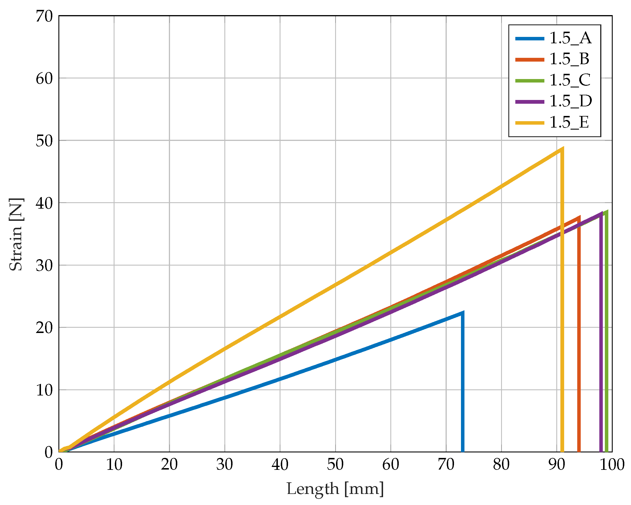
For this tensile study, five specimens ( n = 5 ) were exclusively prepared from sample E3_GlCaCl2_2 of E3 (Table 4), each 2.5 cm wide and 13.5 cm long. Due to minor redistribution of the alginate mixture during drying, slight thickness variations occurred across the foils. The measured thickness ranged from 0.39 mm to 0.97 mm, reflecting typical inhomogeneities in cast hydrogel foils. The tensile properties of the alginate foils are summarized in Table 6 as mean values with standard deviations ( n = 5 ). The samples exhibit an average tensile strength of 2.46 ± 0.43 N / mm 2 and an average elongation at break of 67 ± 7.8 % ( n = 5 ), with a mean thickness of 0.62 ± 0.22 mm .
The stress–strain response was predominantly linear up to fracture, indicating elastic-dominated deformation behavior consistent with Hooke’s law [46]. Although fracture occurred with limited plastic flow, the relatively high elongation values demonstrate substantial flexibility compared with conventional brittle membrane materials. The sharp drop-off at the breaking point reflects brittle fracture, though the substantial elongation before failure suggests a degree of ductility, especially in thicker samples (Figure 20).
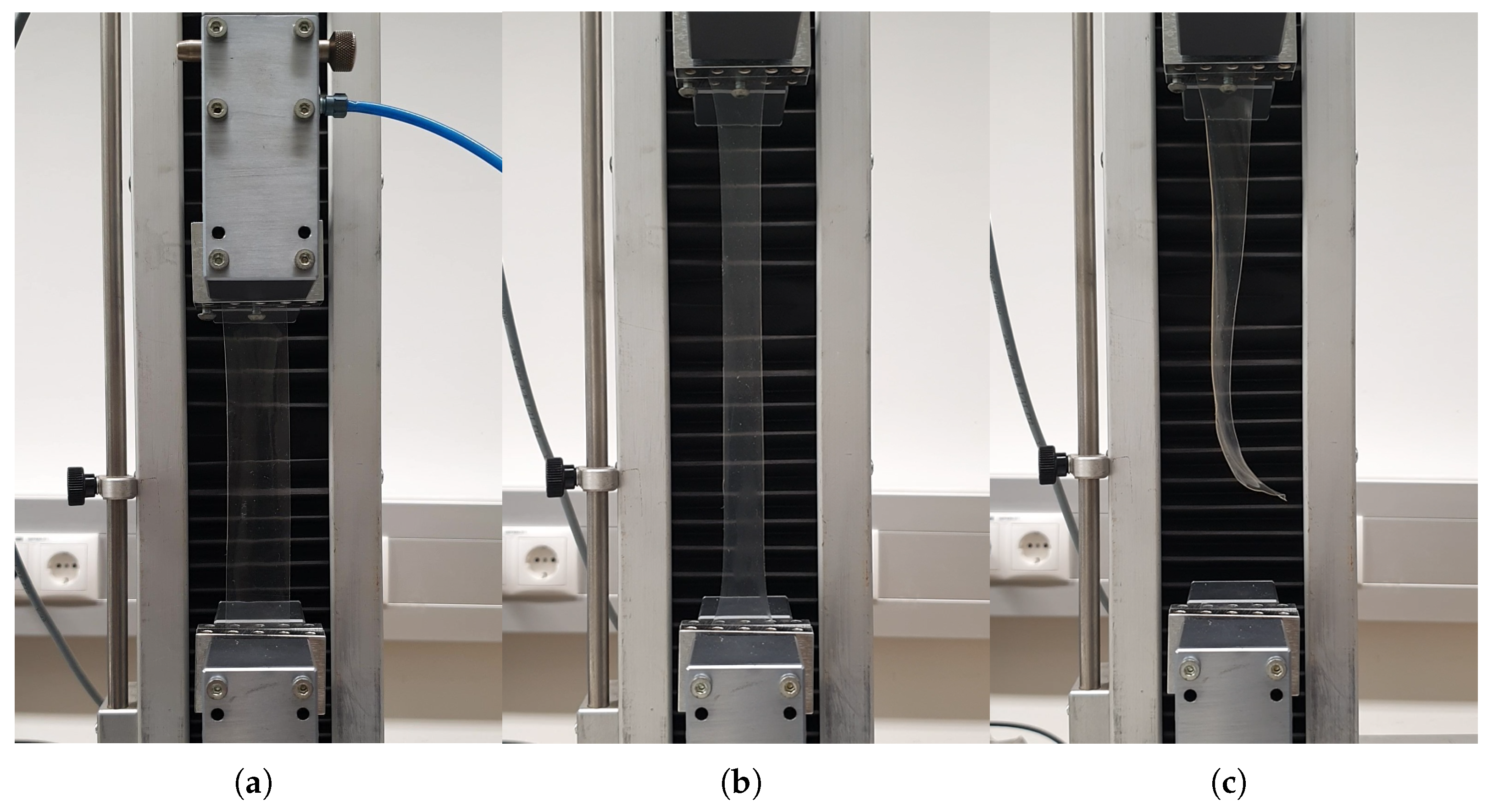
Figure 21 shows specimen 1.5E at three key stages of the test: (a) the initial state before loading, (b) the deformation phase under applied tensile force, and (c) the final state after failure at the clamping area. This indicates that the foil did not fail solely due to the material properties but rather due to stress concentration at the clamp. Despite this, the load–extension curves for all samples consistently demonstrate linear elastic behavior prior to fracture, indicating that the relative mechanical performance between samples is reliably captured.
Variations in the mechanical test results are primarily attributed to differences in foil thickness. Thicker foils exhibit greater stretchability and higher load-bearing capacity due to their increased cross-sectional area, whereas thinner foils are more susceptible to localized stress concentrations and premature failure. Compared to metals or synthetic polymers, alginate foils demonstrate limited plastic deformation but can exhibit notable stretchability under certain conditions. This highlights the critical importance of controlled sample preparation, particularly regarding thickness uniformity, cross-linking density, and moisture content, to ensure consistent and reliable mechanical characterization.

5. Architectural Design Simulation

The integration of alginate-based MPAs into architectural designs introduces a strong sustainability component. However, their use requires careful planning to optimize acoustic performance and ensure durability. By adhering to guidelines, architects can effectively utilize alginate-based MPAs to create acoustically comfortable and sustainable spaces. We conducted acoustic simulations, which constitute a well-established and widely adopted methodology for predicting the acoustic behavior of architectural spaces [47]. Owing to their standardized nature and extensive documentation in the existing literature, the fundamental principles of these simulation methods were not reiterated in detail in the manuscript.
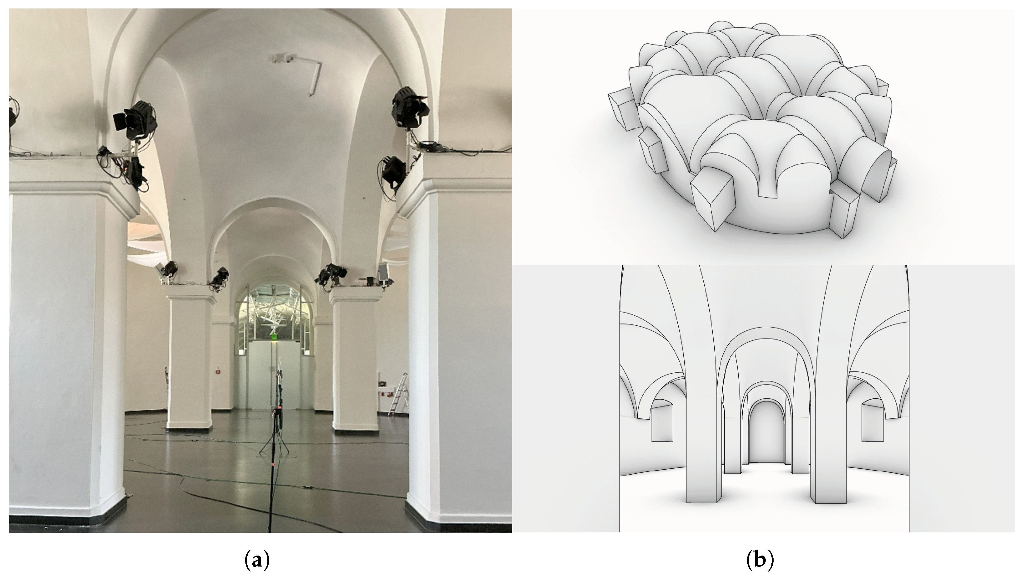
Acoustic simulations were performed using the software TREBLE (web application release 23 October 2025 with geometry processing v2.10.4) [48] for an oval-shaped hall featuring vaulted ceilings, located at the MuseumsQuartier of Vienna, Austria. The aim of this work is to demonstrate the potential of novel materials for improving acoustics in heritage-protected buildings, rather than to present an implemented solution. As the study focuses on the methodological framework rather than practical deployment, full real-world validation lies beyond the scope of this work. The historic and heritage-protected space is intended to be used for events with amplified speeches and music performances. Due to the sound-hard surfaces and long reverberation time, the speech intelligibility should be improved by acoustic means. A picture of the real hall and a 3D model of the hall are shown in Figure 22.
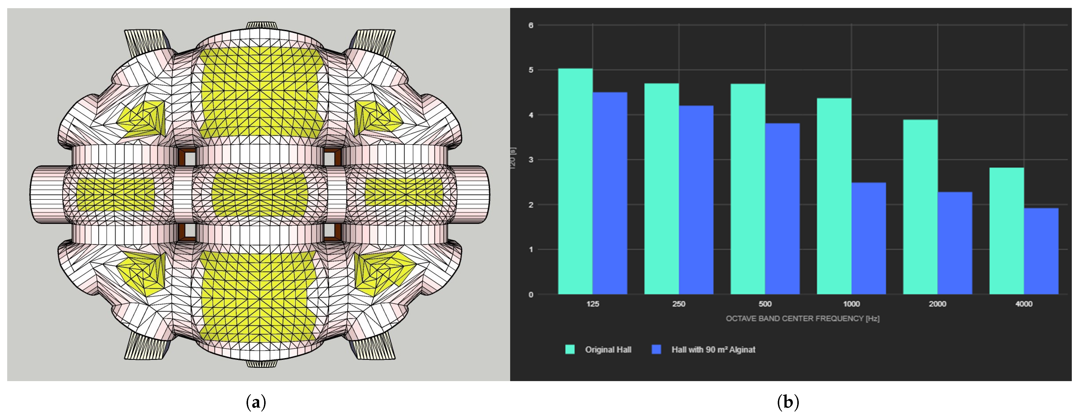
For the first simulation, all surfaces were assumed to be fully sound-hard. Reverberation times (T20) were calculated across frequency bands ranging from 125 Hz to 4000 Hz. To improve the acoustic characteristics, 90 m2 of alginate-based transparent foil was applied to the vaulted ceilings, using the material properties obtained from E1 (see Figure 23). This material is particularly advantageous for heritage-protected buildings, as it provides acoustic absorption without visually obstructing or altering historical surfaces.
The absorption coefficients of the alginate-based foil used in the simulations were initially measured in an impedance tube under normal sound incidence. To account for diffuse field conditions in the hall, the measured values were then converted to random incidence absorption coefficients using Paris’ formula [49]. A comparison of the reverberation times (RT) is shown in Figure 23. The application of this acoustic treatment led to a significant reduction in reverberation times, particularly at mid and high frequencies, demonstrating that heritage-sensitive absorbers can effectively improve the hall’s acoustics while preserving its architectural integrity using sustainable resources. The reverberation time could be decreased at f = 500 Hz from R T = 4.7 s to R T = 3.8 s, and at f = 1000 Hz, it could be reduced from R T = 4.4 s to R T = 2.5 s.
Alginate-based MPAs offer promising opportunities for advancing sustainable architectural acoustics. These versatile foils possess several advantages, including biodegradability, non-toxicity, and the potential for local sourcing, all of which contribute to reducing the environmental impact compared to conventional synthetic materials. Their adaptable nature allows designers to integrate them into a range of architectural applications. This approach provides an innovative and sustainable solution for noise control in large interior spaces. To support transparency and reproducibility, the complete simulation model and the corresponding data are available from the authors upon request.

6. Conclusions

This study demonstrates the significant potential of alginate-based biopolymer foils as a sustainable alternative to traditional plastic materials for acoustic absorption in the construction industry. By leveraging the natural, biodegradable, and non-toxic properties of alginate, the research addresses both the environmental impact of plastic waste and the need for improved acoustic conditions in modern architecture.
The alginate foils were successfully produced and characterized, exhibiting measurable sound absorption, elastic deformation under tensile stress, and overall film flexibility. Sample-specific observations are summarized as follows:
  • Sample E1_CaCl2_1 (E1, laser-perforated): Laser perforation successfully created holes, as chemical perforation was ineffective. The sample exhibited broad micro-perforated absorption, but lower peak absorption and frequency shifts occurred due to variations in hole size and thickness. Thickness ranged from t = 100–160 μm; the film was stable and clear, bendable but not highly flexible, and prone to ripping due to the absence of glycerol.
  • Sample E2_CaCO3_1 (E2): Only a single specimen could be measured due to mechanical fragility. The film showed narrow-band membrane absorption but no micro-perforated behavior, likely caused by unevenly distributed air bubbles and thickness inhomogeneities; results are preliminary.
  • Sample E3_GlCaCl2_1 (E3): Three non-perforated specimens consistently exhibited narrow-band membrane-absorber behavior, with variations due to thickness differences, local inhomogeneities, and mounting sensitivity. Combined with a rear air cavity, these foils can serve as tunable resonant absorbers in low-depth applications.
  • Sample E1_CaCl2_1 (double-layer concept): The double-layer configuration showed enhanced and broadened absorption, maintaining membrane-perforated characteristics with absorption coefficients α 0.4 from 800 to 1408 Hz. Overall absorption was higher than single-layer measurements, with minor deviations at higher frequencies due to setup effects and slight perforation inaccuracies.
  • Sample E3_GlCaCl2_2 (E3, tensile tests): Tensile tests revealed predominantly linear elastic behavior up to fracture, with an average tensile strength of 2.46 ± 0.43 N/mm2 and elongation at break of 67 ± 7.8 %. Thickness variations affected load-bearing capacity and flexibility, highlighting the importance of controlled sample preparation.
The findings of this study provide a solid foundation for the development of environmentally friendly acoustic materials, promoting sustainable practices in the building industry and offering a viable solution to reduce plastic pollution while enhancing indoor acoustic comfort.

7. Future Work

While the feasibility of alginate-based biopolymer foils as acoustic materials has been established, several areas of future research could enhance their practical application and performance. Key areas for further investigation of sample E3_GlCaCl2_1 and E3_GlCaCl2_2, selected for their superior foil formation and acoustic performance, include:
1.
Optimization of Perforation Techniques: Precise control of the perforation process is essential to achieve the desired acoustic performance. Future work will focus on developing controlled perforations in E3 foils to replicate the micro-perforated behavior of the synthetic MPAs tested in Figure 12 ( α reference material), using mechanical or chemical techniques. Furthermore, reducing perforation diameters below 0.25 mm is expected to broaden the absorption bandwidth, enhancing acoustic performance across a wider frequency range.
2.
Material Durability and Performance: Further studies should focus on improving the long-term durability of alginate foils, particularly their resistance to environmental factors such as moisture, UV radiation, and temperature fluctuations. This will be essential for ensuring their suitability for diverse architectural applications. Exploring the integration of additives or coating materials to enhance durability without compromising biodegradability would be a valuable area of research.
3.
Scaling and Industrial Production: Scaling up the production process to create larger panels for architectural use is a key challenge. Future work could explore industrial-scale manufacturing techniques, optimizing the production of large, consistent foils suitable for installation in buildings. Conducting additional acoustic testing in large-scale environments, such as reverberation chambers, would help validate the performance of these materials under real-world conditions.
4.
Multi-layer Designs and Applications: Investigating multi-layered configurations of alginate foils, where different geometric and material properties are combined, could lead to enhanced acoustic absorption across a broader range of frequencies. Additionally, exploring the use of these foils in conjunction with other sustainable materials could open new design possibilities in both temporary and permanent architectural structures.
5.
Life Cycle and Environmental Impact Analysis: As alginate is a biodegradable material, conducting a comprehensive life cycle analysis would help quantify the environmental benefits of these foils in comparison to traditional plastic-based acoustic materials. This could further inform the development of policies and practices that encourage the adoption of biopolymers in the construction industry.

Author Contributions

Conceptualization, M.S. and J.B.; methodology, M.S., J.B., C.O., D.H., K.S.K. and T.M.; validation, C.O., D.H., M.S. and J.B.; formal analysis, C.O. and D.H.; investigation, C.O. and D.H.; resources, M.S.; data curation, C.O. and D.H.; writing—original draft preparation, C.O., D.H., M.S. and J.B.; writing—review and editing, M.S., J.B., C.O., D.H., K.S.K. and T.M.; visualization, C.O.; acoustic simulation, J.B.; supervision, M.S., J.B., K.S.K. and T.M.; project administration, C.O.; funding acquisition, M.S. All authors have read and agreed to the published version of the manuscript.

Funding

This research was funded in whole or in part by the Austrian Science Fund (FWF) [Grant-DOI:10.55776/F77]. For the purpose of open access, the authors have applied a CC BY public copyright license to any Author Accepted Manuscript version arising from this submission.

Institutional Review Board Statement

Not applicable.

Informed Consent Statement

Not applicable.

Data Availability Statement

Data available upon request.

Acknowledgments

We would like to thank Julian Koch and Max Zimmer from SPSC for their support during the impedance tube measurements and Clemens Frischmann for generating the 3D model of the oval hall. Open Access Funding by the Graz University of Technology.

Conflicts of Interest

The authors declare no conflicts of interest.

References

  1. OECD. Global Plastics Outlook: Policy Scenarios to 2060; OECD Publishing: Paris, France, 2022; pp. 1–283. [Google Scholar] [CrossRef]
  2. Iannace, G.; Ciaburro, G.; Guerriero, L.; Trematerra, A. Use of cork sheets for room acoustic correction. J. Green Build. 2020, 15, 45–55. [Google Scholar] [CrossRef]
  3. Berardi, U.; Iannace, G. Acoustic characterization of natural fibers for sound absorption applications. Build. Environ. 2015, 94, 840–852. [Google Scholar] [CrossRef]
  4. Santoni, A.; Bonfiglio, P.; Fausti, P.; Marescotti, C.; Mazzanti, V.; Mollica, F.; Pompoli, F. Improving the sound absorption performance of sustainable thermal insulation materials: Natural hemp fibres. Appl. Acoust. 2019, 150, 279–289. [Google Scholar] [CrossRef]
  5. Mamtaz, H.; Fouladi, M.H.; Al-Atabi, M.; Narayana Namasivayam, S. Acoustic absorption of natural fiber composites. J. Eng. 2016, 2016, 5836107. [Google Scholar] [CrossRef]
  6. Maa, D.Y. Microperforated-panel wideband absorbers. Noise Control Eng. J. 1987, 29, 77–84. [Google Scholar] [CrossRef]
  7. Maa, D.Y. Design of microperforated panel constructions. Acta Acust. 1988, 13, 174–180. [Google Scholar] [CrossRef]
  8. Maa, D.Y. Theory and Design of Microperforated Panel Sound-Absorbing Constructions. 1975. Available online: http://pascal-francis.inist.fr/vibad/index.php?action=getRecordDetail&idt=PASCAL7588507573 (accessed on 30 September 2025).
  9. Herrin, D.; Liu, W.; Hua, X.; Liu, J. A guide to the application of microperforated panel absorbers. Sound Vib. 2017, 51, 12–18. [Google Scholar]
  10. Cox, T.J.; D’Antonio, P. Acoustic Absorbers and Diffusers: Theory, Design and Application, 2nd ed.; Taylor & Francis: London, UK, 2016. [Google Scholar] [CrossRef]
  11. Mei, J.; Ma, G.; Yang, M.; Yang, Z.; Wen, W.; Sheng, P. Dark acoustic metamaterials as super absorbers for low-frequency sound. Nat. Commun. 2012, 3, 756. [Google Scholar] [CrossRef]
  12. Fuchs, H.; Zha, X. Acrylic-glass sound absorbers in the plenum of the Deutscher Bundestag. Appl. Acoust. 1997, 51, 211–217. [Google Scholar] [CrossRef]
  13. Iannace, G.; Ciaburro, G. Modelling sound absorption properties for recycled polyethylene terephthalate-based material using Gaussian regression. Build. Acoust. 2021, 28, 185–196. [Google Scholar] [CrossRef]
  14. Sabbagh, M.; Elkhateeb, A. Sound absorption characteristics of polyurethane and polystyrene foams as inexpensive acoustic treatments. Acoust. Aust. 2019, 47, 285–304. [Google Scholar] [CrossRef]
  15. United Nations Environment Programme Yale Center for Ecosystems + Architecture. Building Materials and the Climate: Constructing a New Future. 2023. Available online: https://wedocs.unep.org/20.500.11822/43293 (accessed on 30 September 2025).
  16. Bierhalz, A.C.; da Silva, M.A.; Braga, M.E.; Sousa, H.J.; Kieckbusch, T.G. Effect of calcium and/or barium crosslinking on the physical and antimicrobial properties of natamycin-loaded alginate films. LWT-Food Sci. Technol. 2014, 57, 494–501. [Google Scholar] [CrossRef]
  17. Arora, B.; Tandon, R.; Attri, P.; Bhatia, R. Chemical crosslinking: Role in protein and peptide science. Curr. Protein Pept. Sci. 2017, 18, 946–955. [Google Scholar] [CrossRef]
  18. Wang, Y.; He, M.; Wu, Y.; Liu, Y.; Ouyang, J. Effect of crosslinking agents on the physicochemical and digestive properties of corn starch aerogel. Starch-Stärke 2021, 73, 2000161. [Google Scholar] [CrossRef]
  19. Cherblanc, F.; Boscus, J.; Bénet, J.C. Electro-osmosis in gels: Application to Agar-Agar. Comptes Rendus. Mécanique 2008, 336, 782–787. [Google Scholar] [CrossRef]
  20. Hariyadi, D.M.; Islam, N. Current status of alginate in drug delivery. Adv. Pharmacol. Pharm. Sci. 2020, 2020, 8886095. [Google Scholar] [CrossRef] [PubMed]
  21. Tønnesen, H.H.; Karlsen, J. Alginate in drug delivery systems. Drug Dev. Ind. Pharm. 2002, 28, 621–630. [Google Scholar] [CrossRef]
  22. Mirdamadi, E.; Tashman, J.W.; Shiwarski, D.J.; Palchesko, R.N.; Feinberg, A.W. FRESH 3D bioprinting a full-size model of the human heart. ACS Biomater. Sci. Eng. 2020, 6, 6453–6459. [Google Scholar] [CrossRef]
  23. Arroyo, B.J.; Bezerra, A.C.; Oliveira, L.L.; Arroyo, S.J.; de Melo, E.A.; Santos, A.M.P. Antimicrobial active edible coating of alginate and chitosan add ZnO nanoparticles applied in guavas (Psidium guajava L.). Food Chem. 2020, 309, 125566. [Google Scholar] [CrossRef] [PubMed]
  24. Cerqueira, M.A.; Leite, A.C.C.; Tomás, A.L.; Reichel, A.; Silva, P.M.; Santos, N.C.; Michelin, M.; Fuciños, P.; Pastrana, L.M. Edible alginate-based films with anti-SARS-CoV-2 activity. Food Microbiol. 2023, 113, 104251. [Google Scholar] [CrossRef] [PubMed]
  25. Jung, S.; Yeo, D.; Wang, Z.; Woo, S.; Seo, Y.; Hossain, M.I.; Choi, C. Viability of SARS-CoV-2 on lettuce, chicken, and salmon and its inactivation by peracetic acid, ethanol, and chlorine dioxide. Food Microbiol. 2023, 110, 104164. [Google Scholar] [CrossRef]
  26. Radoor, S.; Karayil, J.; Jayakumar, A.; Kandel, D.R.; Kim, J.T.; Siengchin, S.; Lee, J. Recent advances in cellulose-and alginate-based hydrogels for water and wastewater treatment: A review. Carbohydr. Polym. 2024, 323, 121339. [Google Scholar] [CrossRef]
  27. Tummino, M.L.; Magnacca, G.; Cimino, D.; Laurenti, E.; Nisticò, R. The innovation comes from the sea: Chitosan and alginate hybrid gels and films as sustainable materials for wastewater remediation. Int. J. Mol. Sci. 2020, 21, 550. [Google Scholar] [CrossRef]
  28. Hallenbeck, P.; Grogger, M.; Mraz, M.; Veverka, D. Solar biofuels production with microalgae. Appl. Energy 2016, 179, 136–145. [Google Scholar] [CrossRef]
  29. Hannon, M.; Gimpel, J.; Tran, M.; Rasala, B.; Mayfield, S. Biofuels from algae: Challenges and potential. Biofuels 2010, 1, 763. [Google Scholar] [CrossRef] [PubMed]
  30. Caniato, M.; Cozzarini, L.; Schmid, C.; Gasparella, A. A sustainable acoustic customization of open porous materials using recycled plastics. Sci. Rep. 2022, 12, 10955. [Google Scholar] [CrossRef] [PubMed]
  31. Qi, L.; Zhi, C.; Meng, J.; Wang, Y.; Liu, Y.; Song, Q.; Wu, Q.; Wei, L.; Dai, Y.; Zou, J.; et al. Highly efficient acoustic absorber designed by backing cavity-like and filled-microperforated plate-like structure. Mater. Des. 2023, 225, 111484. [Google Scholar] [CrossRef]
  32. Marjanovic, I.; Šamec, E.; Stavric, M. Alginate in Architecture-An Experimental Approach to the New Sustainable Building Material. In Proceedings of the SmartART 2021; Serbian Academy of Sciences and Arts: Belgrade, Serbia, 2021; pp. 1–18. [Google Scholar] [CrossRef]
  33. Fuchs, H.V. Raum-Akustik und Lärm-Minderung: Konzepte mit Innovativen Schallabsorbern und -Dämpfern, 4th ed.; Springer: Berlin/Heidelberg, Germany, 2017. [Google Scholar]
  34. Maa, D.Y. Potential of microperforated panel absorber. J. Acoust. Soc. Am. 1998, 104, 2861–2866. [Google Scholar] [CrossRef]
  35. International Organization for Standardization. Acoustics—Determination of Acoustic Properties in Impedance Tubes —Part 2: Two-Microphone Technique for Normal Sound Absorption Coefficient and Normal Surface Impedance. 2023. Available online: https://www.iso.org/standard/81294.html (accessed on 30 September 2025).
  36. Sakagami, K.; Yairi, M.; Morimoto, M. Multiple-Leaf Sound Absorbers with Microperforated Panels: An Overview. 2010. Available online: https://www.acoustics.asn.au/journal/AAAugust10.pdf#page=24 (accessed on 30 September 2025).
  37. Houben, S.; Pitet, L.M. Ionic crosslinking strategies for poly (acrylamide)/alginate hybrid hydrogels. React. Funct. Polym. 2023, 191, 105676. [Google Scholar] [CrossRef]
  38. Shahriari, D.; Koffler, J.; Lynam, D.A.; Tuszynski, M.H.; Sakamoto, J.S. Characterizing the degradation of alginate hydrogel for use in multilumen scaffolds for spinal cord repair. J. Biomed. Mater. Res. Part A 2016, 104, 611–619. [Google Scholar] [CrossRef] [PubMed]
  39. Gao, S.K.; Yin, R.; Wang, X.C.; Jiang, H.N.; Liu, X.X.; Lv, W.; Ma, Y.; Zhou, Y.X. Structure characteristics, biochemical properties, and pharmaceutical applications of alginate lyases. Mar. Drugs 2021, 19, 628. [Google Scholar] [CrossRef]
  40. Liu, Q.; Li, Q.; Xu, S.; Zheng, Q.; Cao, X. Preparation and properties of 3D printed alginate–chitosan polyion complex hydrogels for tissue engineering. Polymers 2018, 10, 664. [Google Scholar] [CrossRef] [PubMed]
  41. Tong, R.; Ma, Z.; Yao, R.; Gu, P.; Li, T.; Liu, L.; Guo, F.; Zeng, M.; Xu, J. Stretchable and transparent alginate ionic gel film for multifunctional sensors and devices. Int. J. Biol. Macromol. 2023, 246, 125667. [Google Scholar] [CrossRef] [PubMed]
  42. Smidsrød, O.; Glover, R.; Whittington, S.G. The relative extension of alginates having different chemical composition. Carbohydr. Res. 1973, 27, 107–118. [Google Scholar] [CrossRef]
  43. Cano-Vicent, A.; Martínez-Agut, A.; Tuñón-Molina, A.; Bakshi, H.; i Serra, R.S.; Alfagih, I.M.; Tambuwala, M.M.; Serrano-Aroca, Á. In vivo and in vitro biocompatible alginate film crosslinked with Ca2+ and Co2+ manifests antiviral, antibacterial and anticancer activity. Eur. Polym. J. 2023, 197, 112377. [Google Scholar] [CrossRef]
  44. Kuo, C.K.; Ma, P.X. Maintaining dimensions and mechanical properties of ionically crosslinked alginate hydrogel scaffolds in vitro. Biomed. Mater. Res. 2008, 84, 899–907. [Google Scholar] [CrossRef]
  45. DIN EN 61000-4-2/VDE 0847-4-2:2009-12; Electromagnetic Compatibility (EMC)—Part 4-2: Testing and Measurement Techniques—Electrostatic Discharge Immunity Test (IEC 61000-4-2:2008). Austrian Standards: Heinestrasse, Vienna, 2009. Available online: https://www.austrian-standards.at/de/shop/din-en-61000-4-2-vde-0847-4-2-2009-12~p1774340 (accessed on 30 September 2025).
  46. Buhungo, T.J.; Supartin, S.; Arbie, A.; Setiawan, D.G.E.; Djou, A.; Yunus, M. Learning Tools Quality of Problem-Based Learning Model in Contextual Teaching and Learning Approach on Elasticity and Hooke’s Law Materials. 2023. Available online: https://jppipa.unram.ac.id/index.php/jppipa/article/view/3127 (accessed on 30 September 2025).
  47. Vorländer, M. Auralization: Fundamentals of Acoustics, Modelling, Simulation, Algorithms and Acoustic Virtual Reality; Springer: Berlin/Heidelberg, Germany, 2007. [Google Scholar] [CrossRef]
  48. Treble Technologies. Acoustic Simulation Platform for Machine Learning & AI. 2025. Available online: https://www.treble.tech/ (accessed on 29 October 2025).
  49. Paris, E. On the reflexion of sound from a porous surface. Proc. A 1927, 115, 407–419. [Google Scholar] [CrossRef]
Figure 1. Schematic representation of an MA. The arrow indicates the possible membrane deflection.
Buildings 16 01035 g001
Figure 2. Sketch of the relevant MPA geometry parameters [8].
Buildings 16 01035 g002
Figure 3. Equivalent electrical circuit analogy of an MPA with two layers in front of a rigid wall.
Buildings 16 01035 g003
Figure 4. (a) Impedance tube equipped with four microphones indicated by red markings. (b) Sample preparation within a customized acrylic glass frame. (c) Sample installed in the mounting device.
Buildings 16 01035 g004
Figure 5. Formulation process of alginate foil.
Buildings 16 01035 g005
Figure 6. Excavating process alginate foil from petri dish—sample E1_CaCl2_1: (a) the invisible alginate foil adheres to the Petri dish, with the red marking indicating its engraved brand name, (b) the foil is gently peeled off, demonstrating flexible properties during detachment, (c) the removed foil shows a detailed replication of the engraved brand name, capturing fine surface details, (d) the bending behavior highlights the foil’s mechanical stability.
Buildings 16 01035 g006
Figure 7. Alginate glycerin films with different amounts of bubbles, (a) with 0.36% of CaCO3, (b) with 1.14% of CaCO3.
Buildings 16 01035 g007
Figure 8. Alginate film under an electron microscope, where closed pores are visible, (a) sample after 24 h in HCl bath, (b) triple enlarged view.
Buildings 16 01035 g008
Figure 9. Alginate–glycerin foil samples exhibiting high optical transparency and pronounced flexibility: (a) E3_GlCaCl2_1 excavated from round petri dish suitable for an acoustic measurement setup, and (b) E3_GlCaCl2_2 upscaled rectangle shape foil for tensile testing.
Buildings 16 01035 g009
Figure 10. Absorption coefficients calculated with parameters from Table 5.
Buildings 16 01035 g010
Figure 11. When the foil is perforated by using a laser cutter, the holes are burned into the material causing a brown discolouration, (a) clear film, (b) perforation applied, (c) sample in frame.
Buildings 16 01035 g011
Figure 12. Measured normal-incidence absorption coefficient of one E1 laser-perforated alginate sample and a commercial reference MPA film, calculated curve for E1 using b = 2 mm , d = 0.32 mm , t = 160 μ m , and D = 5 cm .
Buildings 16 01035 g012
Figure 13. Normal-incidence absorption coefficient of the E1 specimens ( n = 3 ). The black line represents the specimen-averaged mean, while the pink shaded area indicates the min–max range across specimens, reflecting specimen-to-specimen variability.
Buildings 16 01035 g013
Figure 14. Absorption curve E2, t = 164 μm, D = 5 cm.
Buildings 16 01035 g014
Figure 15. Non-perforated alginate film from E3_GlCaCl2_1: (a) Measuring the thickness No. 2; (b) all three specimens clamped and prepared for measurements; (c) specimen in the impedance tube.
Buildings 16 01035 g015
Figure 16. Measured normal-incidence absorption coefficients for three non-perforated E3_GlCaCl2 specimens with a 52 mm air cavity. The different colors correspond to specimens Nr2, Nr4, and Nr6, while solid, dashed, and dotted lines represent repeated measurements at 0 ° , + 30 ° , and 30 ° sample rotation, respectively.
Buildings 16 01035 g016
Figure 17. Normal-incidence absorption coefficient of three independent non-perforated E3 specimens ( n = 3 ) with a 52 mm air cavity. The black line represents the specimen-averaged mean absorption coefficient, while the pink shaded area indicates the min–max range across specimens. Each specimen curve was obtained by averaging repeated measurements at 0 ° and ± 30 ° sample rotation.
Buildings 16 01035 g017
Figure 18. (a) Double-layer setup with perforated alginate samples (b) side-view, distance D variable.
Buildings 16 01035 g018
Figure 19. DL01 measurement compared to simulated data.
Buildings 16 01035 g019
Figure 20. Tensile test results illustrating the load progression [N] in relation to strain length [mm] factors.
Buildings 16 01035 g020
Figure 21. Specimen 1.5 E (a) is shown in its original state at the start of the tensile test. The alginate foil is flat, not tensioned, and clamped securely between the upper and lower grips. (b) The sample is significantly elongated just before failure, highlighting its substantial stretchability under tension. (c) The sample after failure, showing a distinct break at the clamping area.
Buildings 16 01035 g021
Figure 22. (a) Picture of the oval hall and (b) 3D model for acoustic simulation.
Buildings 16 01035 g022
Figure 23. (a) Placement of the alginate foil is marked by the yellow region. (b) Simulated reverberation time T20, in the hall without any acoustic treatment (green bars) and with 90 m2 alginate foil on the ceiling (blue bars).
Buildings 16 01035 g023
Table 1. Experimental plan for alginate-based foils (E1E3).
ExperimentNumber of SamplesVariables/
Additives
Measured PropertiesMethodQualitative Observations
E15SAL, CaCl2, H2OAcoustic absorption coefficientImpedance tubeBendable, dissolvable, transparent
E23SAL, Gl, CaCO3, HCl, H2O;Acoustic absorption coefficientOptical microscopy, impedance tubeClosed air bubbles, water-resistant
E32SAM, Gl, CaCl2, H2O;Acoustic absorption coefficient, tensile strength;Tensile testing machine, impedance tubeWater-resistant, flexible, transparent
Table 2. Composition of samples with different CaCl2 contents. All samples were prepared so that the total mass of each formulation equaled 100 g.
SampleSAL [wt%]H2O 1 [wt%]CaCl2 [wt%]H2O 2 [wt%]Number of Specimens
E1_CaCl2_12930.0364.9643
E1_CaCl2_22930.0724.9283
E1_CaCl2_32930.1084.8923
E1_CaCl2_42930.1444.8563
E1_CaCl2_52930.184.823
1 Water used for dissolving sodium alginate during preparation of the alginate solution (AL). 2 Water used to prepare the CaCl2 solution. Calculated as: H2O2 = 100 wt% − (SAL + H2O1 + CaCl2), so that the total mass of each sample equals 100 g.
Table 3. Composition of samples with varying CaCO3 content, where each CaCO3 concentration was paired with a corresponding HCl concentration optimized to maintain proper reaction conditions.
SampleSAL [wt%]H2O [wt%]Gl [wt%]CaCO3 [wt%]HCl [M]Number of Specimens
E2_CaCO3_1288100.360.0723
E2_CaCO3_2288100.720.1443
E2_CaCO3_3288101.140.2883
Table 4. Composition for alginate foil in E3.
SampleSAM [wt%]H2O 1 [wt%]Gl [wt%]CaCl2 [wt%]H2O 2 [wt%]CaCl2 [M]Number of Specimens
E3_GlCaCl2_128850.364.960.53
E3_GlCaCl2_228850.364.960.55
1 Water used for dissolving sodium alginate during preparation of the alginate solution (AL). 2 Water used for preparing the CaCl2 solution, following the procedure used for E1.
Table 5. Parameter sweep for a single-layer MPA ( D = 5 cm).
Cased [μm]b [μm] ϵ [%] f 0 [Hz] α max
130602016760.99
2601601116150.91
3802201016150.74
41005003.1414350.97
520020000.799530.98
Table 6. Tensile test samples from E3.
SampleSpecimenThickness
[mm]
  Max. Stress
[N/mm2]
Elongation
at Break
[%]
E3_GlCaCl2_21.5_A0.392.3154
1.5_B0.483.1468
1.5_C0.602.5773
1.5_D0.672.2973
1.5_E0.972.0067
Mean ± SD 0.62 ± 0.222.46 ± 0.4367 ± 7.8
Disclaimer/Publisher’s Note: The statements, opinions and data contained in all publications are solely those of the individual author(s) and contributor(s) and not of MDPI and/or the editor(s). MDPI and/or the editor(s) disclaim responsibility for any injury to people or property resulting from any ideas, methods, instructions or products referred to in the content.