Article

Influences of Inclination Angles and Loading Scenarios on the Elasto-Plastic Stability of a Steel Basket-Handle Arch Structure

1
School of Urban Construction, Tianjin College, University of Science and Technology Beijing, Tianjin 301830, China
2
School of Transportation and Geomatics Engineering, Shenyang Jianzhu University, Shenyang 110168, China
3
State Key Laboratory of Bridge Safety and Resilience, Beijing University of Technology, Beijing 100124, China
*
Author to whom correspondence should be addressed.
Buildings 2026, 16(5), 1013; https://doi.org/10.3390/buildings16051013
Submission received: 24 January 2026 / Revised: 15 February 2026 / Accepted: 2 March 2026 / Published: 4 March 2026

Abstract

This study investigates the effects of an arch rib inclination angle and loading scenario on the elasto-plastic stability of steel basket-handle arches to support bridge design. A parametric finite element analysis was performed on 48 models, with inclination angles ranging from 0° to 15° under three vertical loading conditions: uniformly distributed (V), transversely eccentric (V1), and longitudinally eccentric (V2). A nonlinear analysis was conducted using the arc-length method. The results indicate that the ultimate bearing capacity is highest under loading V, followed by V1 and V2, irrespective of the inclination angle. The initial stiffness increases monotonically with inclination in all cases. Under V, the capacity peaks at a 10° inclination before declining, with a corresponding transition from out-of-plane to in-plane buckling at this critical angle. Under V1, out-of-plane buckling dominates, and the capacity fluctuates slightly before increasing with the inclination. Under V2, in-plane antisymmetric buckling prevails, and the capacity decreases gradually as the inclination increases. Eccentric loading induces severe stress concentration and local buckling at the arch feet, accelerating global failure. It is concluded that an inclination angle up to 10° enhances elasto-plastic stability under symmetric vertical loading, whereas eccentric loading substantially reduces the capacity; therefore, symmetric and simultaneous loading on both arches is recommended during construction.

1. Introduction

Steel arch ribs with box sections, known for their excellent spanning capacity and versatile design configurations, have been widely applied in bridge engineering in recent years [1,2,3]. However, as bridge spans increase, stability concerns, including both in-plane and out-of-plane stability under vertical loads, have become increasingly prominent [4,5]. Pi et al. [6,7] conducted a buckling analysis on three-dimensional (3D) finite element models (FEMs) of fixed steel arch structures to study the in-plane elasto-plastic buckling modes and ultimate strength under compression and bending conditions, and proposed a formula for the calculation of the in-plane and out-of-plane ultimate bearing capacity of steel arch ribs under combined bending and compression. Guo et al. [8,9] investigated the out-of-plane elasto-plastic buckling strength of steel arch structures through experimental and finite element (FE) analysis. The study results indicate that, when the test arches reach their load-carrying capacity, plastic zones form in the arch rib, and the out-of-plane flexural–torsional deformation is significant. The results show that the out-of-plane buckling strength of steel arches under asymmetric loading is lower than that under symmetric loading.
The longer the span of a bridge, the weaker its out-of-plane stability: in a steel box arch bridge, the results indicate that an inward inclination of arch ribs (called basket-handle arch ribs), which enhances the lateral stability of such bridges, is thus widely adopted in the construction of long-span steel arch bridges [10,11]. Subsequently, scholars have widely adopted experimental and FE analysis methods to assess the effects of the rise–span ratio, width–span ratio, the inclination angle, bending–torsion coupling and non-conservative force effect on the stable bearing capacity of arch structures. The results indicate that the non-conservative force effect should be taken into account when calculating the out-of-plane ultimate bearing capacity of basket-handle arch bridges; otherwise, the calculated results will be smaller than the actual values. Additionally, the ultimate bearing capacity of arch ribs first increases, then decreases, with an increasing rise–span ratio and inclination angle [12,13,14,15,16]. Zhao et al. [17,18] established a spatial FEM based on the engineering background of a certain deck-type steel basket-handle arch bridge to evaluate the effects of the rise–span ratio and inclination angle on the elastic buckling stability coefficient of the arch bridge. The results show that, with the increase in the inclination angle, the first-order out-of-plane stability coefficient of the arch bridge increases quasi-linearly, while the first-order in-plane stability coefficient shows a downward trend.
While the above studies have laid a solid foundation for the design and analysis of steel arch bridges [19,20,21,22], they exhibit deficiencies in two key aspects: first, an excessively large inclination angle may induce torsional instability in the arch ribs, yet the underlying mechanisms and parametric influences remain inadequately understood; second, during the construction and operational stages of bridges, arch ribs are subjected to diverse, complex loading scenarios, which can trigger various modes of instability such as in-plane antisymmetric buckling. Moreover, current studies often lack systematic investigations of the combined effects of the inclination angle and realistic asymmetric loading conditions on the elasto-plastic stability and the transition of failure modes of the structure. To address these gaps, the authors established detailed 3D FEMs of basket-handle arch ribs with a box section. Through parametric analysis, these were used to investigate the influences of different inclination angles on the ultimate bearing capacity and deformation characteristics of the structure under three typical loading scenarios: uniformly distributed vertical loading, transversely eccentric vertical loading, and longitudinally eccentric vertical loading. The findings provide a more precise theoretical basis for the stability-oriented design and optimization of steel basket-handle arch bridges.

2. Overview of the Steel Basket-Handle Arch Structure

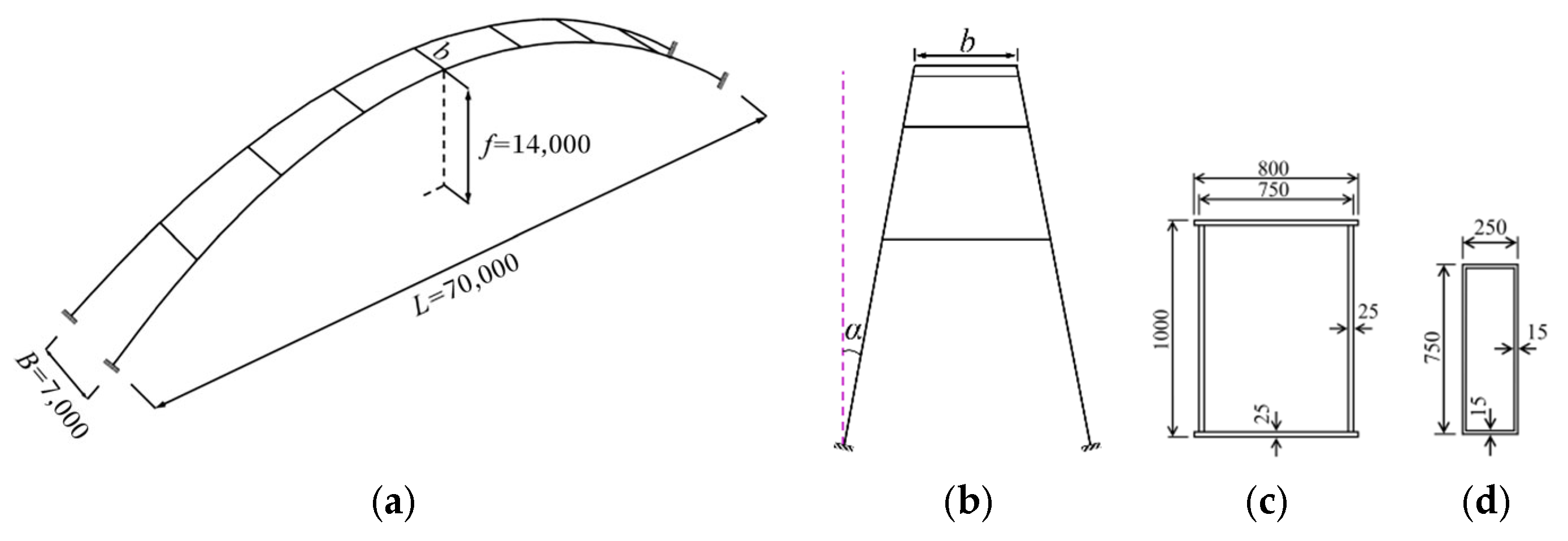
This study primarily examines the influences of the inclination angle of twin arch ribs with box section and loading scenarios on the stability performance of the steel basket-handle arch. To this end, a steel arch structure consisting of two arch ribs and lateral bracings is used as the research object, with its configuration shown in Figure 1. As shown in Figure 1a,b, L represents the span of the arch rib, L = 70,000 mm; f is the rise in the arch, f = 14,000 mm; B denotes the width between the arch ribs at the springing, B = 7000 mm; the arch axis follows a parabolic curve with a rise–span ratio of 0.2; seven lateral bracing elements are evenly spaced between the two arch ribs; α represents the inward inclination angle of the arch ribs; and b is the width between the arch ribs at the vault. Both the arch ribs and the lateral bracings feature welded box sections, with the cross-sectional dimensions of the arch ribs and the vault bracing detailed in Figure 1c,d, respectively. Due to the inward inclination of the arch ribs, the thickness of the flange plate and web plate of the other lateral bracing section is adjusted accordingly to ensure that the lateral stiffness provided by the other bracings is consistent with that of the vault bracing.

3. Parameter Determination

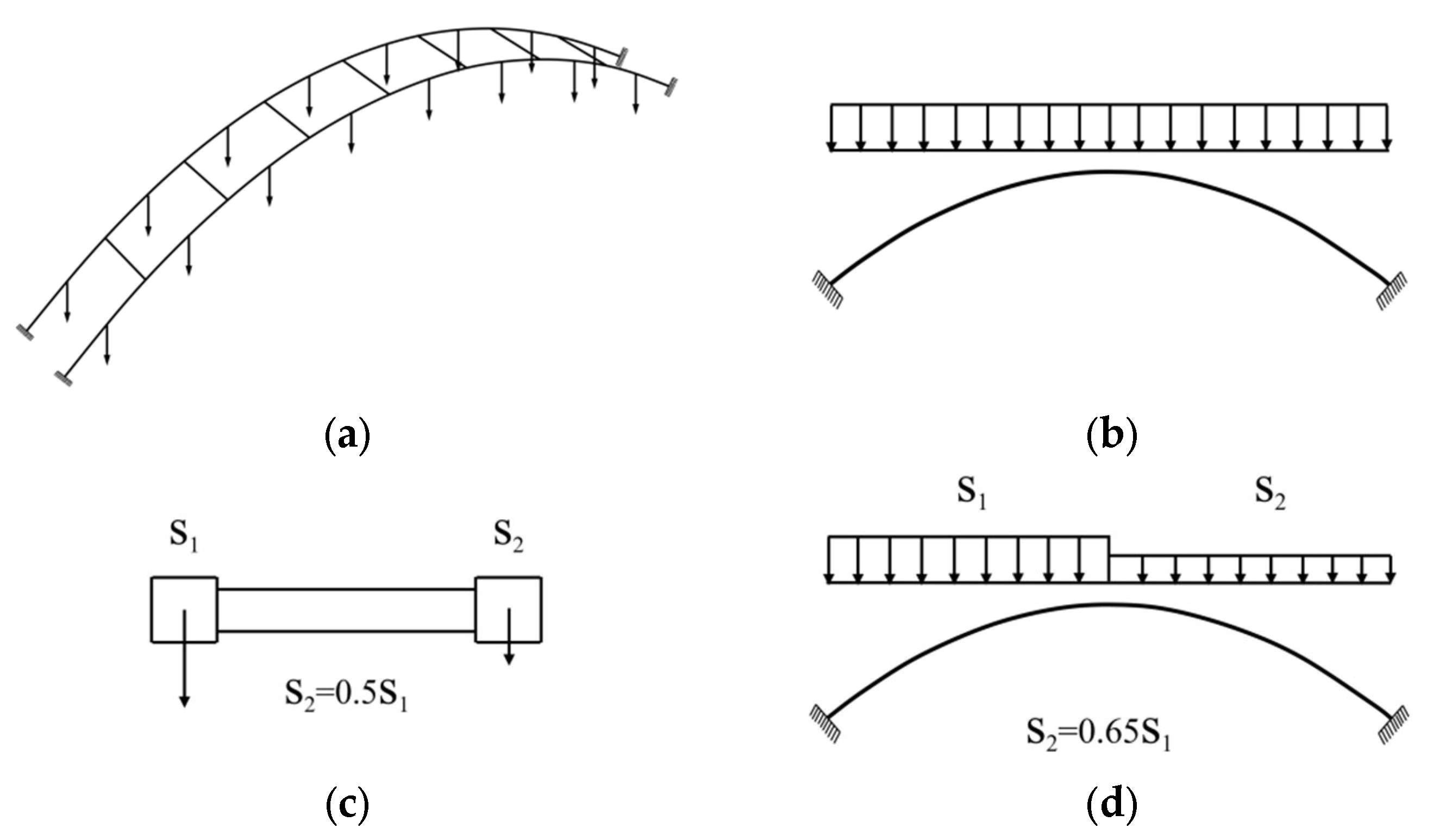
This study adopted the inclination angle α of arch ribs as the primary design parameter of the steel box basket-handle arch. By varying this angle from 0° to 15° in 1° intervals, a total of 16 distinct arch models is established. Considering that arch ribs are subject to different loading scenarios that may induce distinct instability modes during both construction and operation, three characteristic vertical loading configurations are specified, as illustrated in Figure 2.
To investigate the effects of load eccentricity on the elasto-plastic stability of steel basket-handle arches, three representative loading scenarios were designed based on the typical eccentric conditions encountered during bridge construction and service. Loading scenarios: Vertical concentrated loads are applied at the midpoints between every two lateral bracings on each arch rib, resulting in a total of 16 loading points for the entire arch structure (Figure 2a). Steel box basket-handle arch bridges during both construction and operation may be subjected to various loading scenarios, which could potentially excite different modes of instability in the arch structure. To simulate the effects of eccentric loading caused by factors such as varying dead loads from the spandrel structure during construction or dynamic vehicle loads during operation, in addition to the uniformly distributed vertical loading scenario (referred to as “Uniformly Distributed Vertical Load”) V (Figure 2b), two other loading scenarios are established: the transverse bridge-direction eccentric vertical loading scenario (referred to as “Transversely Eccentric Vertical Load”) V1 (Figure 2c) and the longitudinal bridge-direction eccentric loading scenarios (referred to as “Longitudinally Eccentric Vertical Load”) V2 (Figure 2d). In the transversely eccentric vertical loading scenario (V1), the load ratio between the two arch ribs is 1:0.5 (S2 = 0.5S1). In the longitudinally eccentric vertical loading scenario (V2), the load ratio between the left and right half-spans of the arch structure is 1:0.65 (S2 = 0.65S1) [23,24,25]. While the present study focuses on vertical loading, the elasto-plastic behavior of steel basket-handle arches under horizontal cyclic loading has been systematically investigated by Wang et al. [18]. The loading is applied in an incremental manner until structural failure occurs. The design parameters and loading scenarios for the steel box basket-handle arch structure are summarized in Table 1.

4. FEM of the Steel Box Basket-Handle Arch Structure

4.1. FE Types and Material Constitutive Model

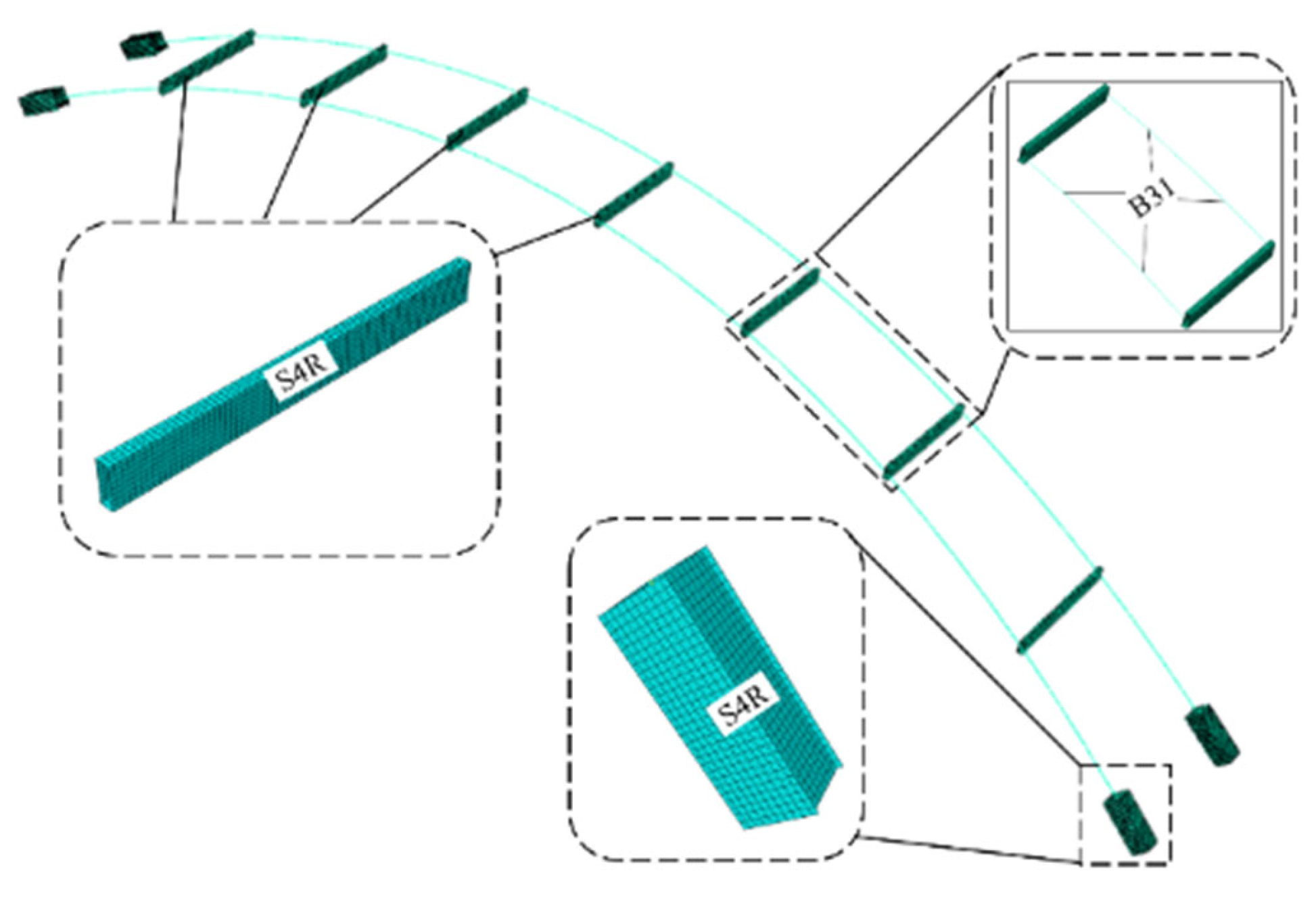
A 3D beam-shell mixed-element model of the steel box basket-handle arch was developed using ABAQUS, and the analysis was conducted using the arc-length method. During the loading process, the structure enters a plastic state, and local buckling deformation may occur in certain components. Therefore, at locations prone to buckling, such as the arch ribs near the arch foot and the lateral bracings, a 3D shell element (S4R) with good adaptability was used for modeling. For the remaining sections, a Timoshenko beam element (B31), which accounts for shear stress and rotational inertia, was used. The connection between the beam and shell elements was established using a coupling constraint. Each finite element model contains approximately 16,407 elements, including 15,582 shell elements and 825 beam elements. The 3D model is illustrated in Figure 3.
The material properties of the steel components in the analysis model are shown in Table 2. After entering the elasto-plastic phase, a bi-linear kinematic hardening constitutive model is used for the steel, with the hardening modulus taken as 0.01 times the elastic modulus.

4.2. Boundary Conditions

The boundary conditions are applied at the four arch footings of the model, where all translational degrees of freedom in the longitudinal (x), vertical (y), and lateral (z) directions, alongside all rotational degrees of freedom, are fully constrained.

4.3. Validation of Model Effectiveness

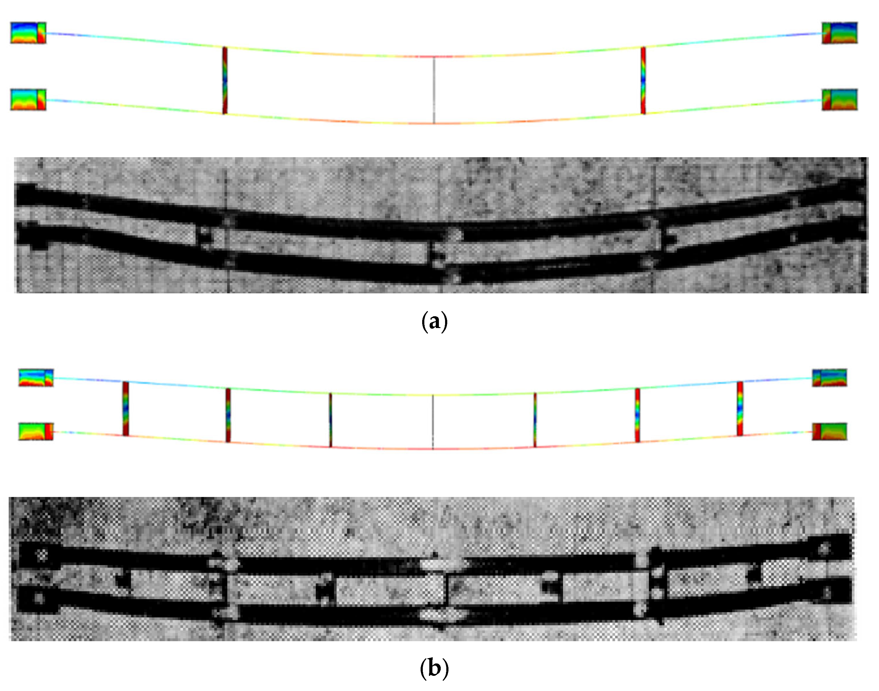
To validate the rationality of the aforementioned modeling method and the validity of the analysis results, the FEM based on the test specimen [24] was established. The simulated ultimate bearing capacity was compared with the experimental ultimate bearing capacity. The geometric dimensions of the test specimen and a comparison between the experimental and FE analysis results are displayed in Table 3. Figure 4 demonstrates a comparison of the buckling modes.
As shown in Table 3 and Figure 4, the ultimate bearing capacity obtained from the FE simulation analysis agrees well with the experimental results (all errors being within 5%). The buckling mode derived from the FE analysis is also largely consistent with that observed in the test specimen, both being out-of-plane instability. Therefore, it can be concluded that the modeling approach using the beam–shell mixed-element model, the selection of element types, the parameter settings for the material constitutive relationship, and the boundary conditions adopted in this study are reasonable and effective, and the analytical results are accurate.

5. Analysis of the Stability Performance of Steel Box Basket-Handle Arches

5.1. Influence of the Inclination Angle α on the Reaction Force–Lateral Horizontal Displacement

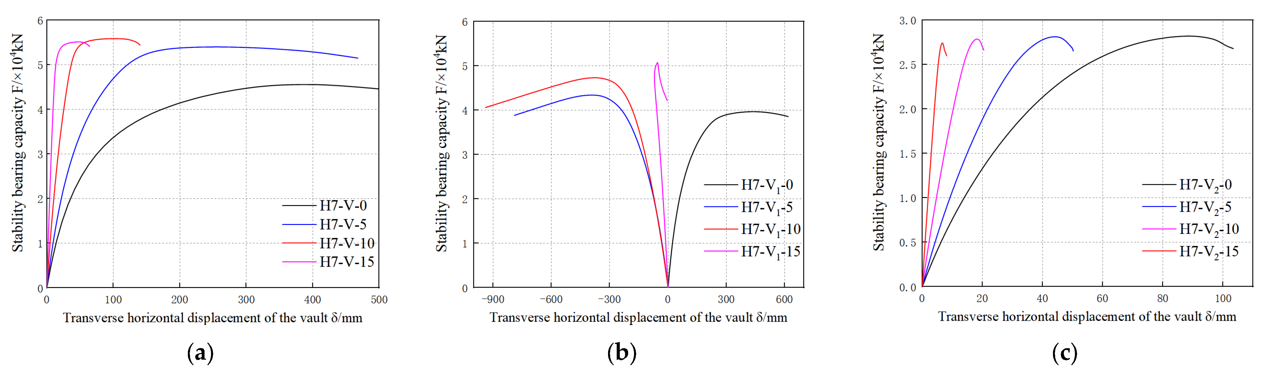
To estimate the influence of the arch rib inclination angle on the stability performance of the steel box basket-handle arch structure, the curves illustrating horizontal reaction force–lateral horizontal displacements at the vault for arches with inclination angles α of 0°, 5°, 10°, and 15° under three vertical loading scenarios are compared (Figure 5). Figure 5a presents the analytical results for loading scenario V (uniformly distributed vertical load), Figure 5b shows the results for loading scenario V1 (transversely eccentric vertical load), and Figure 5c displays the results for loading scenario V2 (longitudinally eccentric vertical load). In the figures, the vertical axis represents the total vertical reaction force at the four arch footings of each model, and the horizontal axis (lateral displacement) denotes the lateral displacement at the vault of each model.
Figure 5 shows that, under the three loading scenarios, the initial stiffness of the steel box basket-handle arch significantly improves with an increase in the inclination angle α. After reaching the maximum bearing capacity, the load-carrying capacity of the structure declines rapidly, and the displacement corresponding to the maximum bearing capacity gradually decreases with the increase in α. However, Figure 5b demonstrates that, under loading scenario V1, the lateral displacement direction of the steel box arch with α = 0° is opposite to that of the other three models. This finding indicates that, as the inclination angle increases in the basket-handle arch structure, the direction of instability deformation under eccentric loading may potentially reverse.

5.2. Influence of Loading Scenarios on the Reaction Force–Lateral Horizontal Displacements

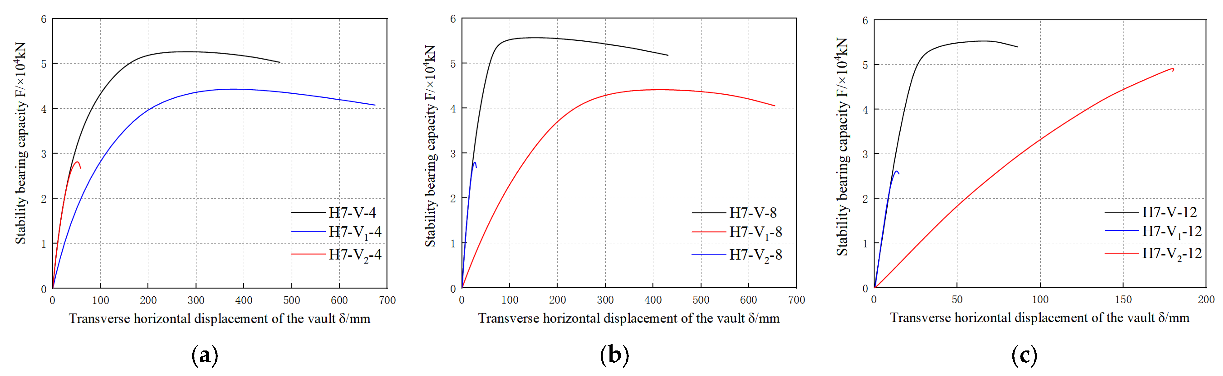
Figure 6 shows the curves illustrating the reaction force–lateral horizontal displacements at the vault for basket-handle arch structures under the three loading scenarios, when the arch rib inclination angles α are 4°, 8°, and 12°, respectively.
It can be seen from Figure 6 that, for inclination angles α = 4°, 8°, and 12°, the arch structure under loading scenario V exhibits the highest ultimate bearing capacity. The ultimate bearing capacity under loading scenario V1 ranks second, while that under loading scenario V2 is the lowest, being approximately half of the capacity under loading scenario V. After reaching the maximum bearing capacity, the load-carrying capacity of the structure under loading scenario V1 decreases at the slowest rate, with the largest displacement corresponding to the peak load. In contrast, the capacity under loading scenario V2 decreases most rapidly, accompanied by the smallest displacement at peak load. Additionally, the initial stiffness of the structures under loading scenarios V and V2 is essentially the same and higher than that under loading scenario V1. In summary, the performance differences under the three loading scenarios imply that the load symmetry is the primary factor governing the ultimate bearing capacity, post-buckling behavior, and initial stiffness of the basket-handle arch. Symmetrically distributed loading (Scenario V) best mobilizes the structure’s load-bearing potential and ductility.

5.3. Influences of the Inclination Angle α and Loading Scenario on the Buckling Modes and Stability

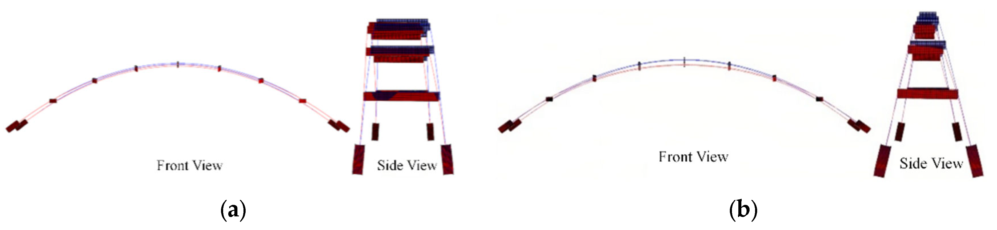
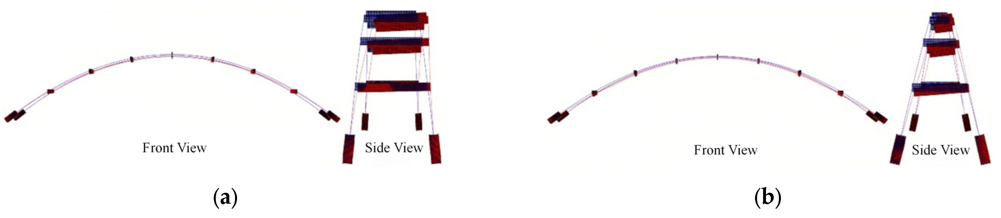
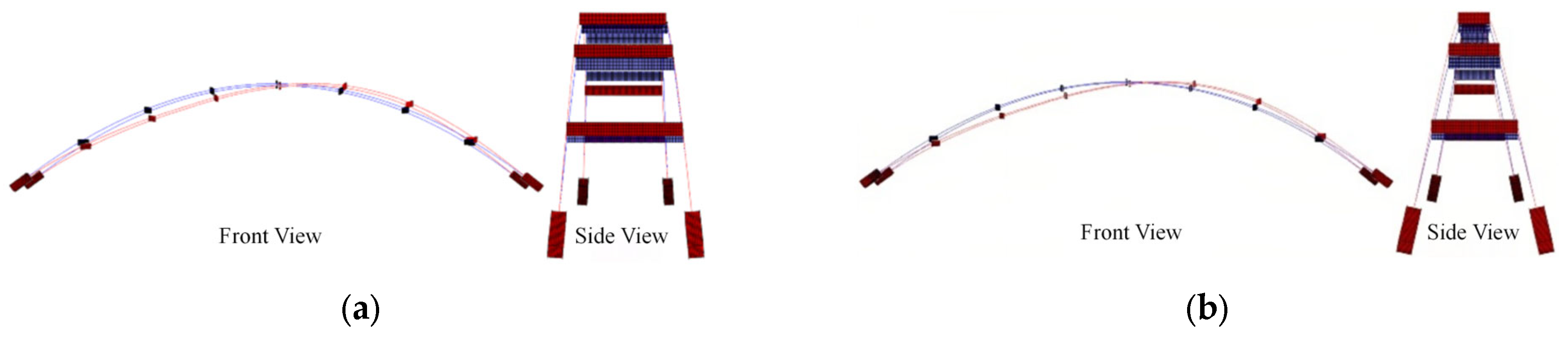
To investigate the influences of the inclination angle α and loading scenarios on the buckling modes of the arch structure, the deformation results at the maximum ultimate bearing capacity for six models with arch rib inclination angles α of 4° and 12° under the three loading scenarios were compared (Figure 7, Figure 8 and Figure 9). Furthermore, the ultimate bearing capacity, the corresponding lateral displacement at the vault, and the associated buckling modes obtained from the elasto-plastic stability analysis of all 48 FEMs for the steel box basket-handle arch structure are summarized in Table 4.
As shown in Figure 7, under loading scenario V, when the basket-handle arch structure with α = 4° reaches its maximum bearing capacity, the deformation is primarily characterized by lateral out-of-plane instability. In contrast, when the structure with α = 12° reaches its peak load, the deformation is dominated by vertical in-plane symmetric instability. Figure 8 indicates that, under loading scenario V1, the deformations of basket-handle arch structures with both inclination angles at their maximum bearing capacity are mainly characterized by lateral out-of-plane instability. Figure 9 shows that, under loading scenario V2, the deformations of basket-handle arch structures with both inclination angles at their ultimate bearing capacity are primarily characterized by vertical in-plane anti-symmetric instability.
As shown in Table 4, under loading scenario V, when the inclination angle is increased from 0° to 10°, the ultimate bearing capacity of the arch structure increases with the inclination angle, showing an improvement of 22.59%. When the inclination angle is increased from 10° to 15°, the ultimate bearing capacity decreases as the inclination angle increases, with a reduction of 1.43%. Across the inclination range of 0° to 15°, the lateral displacement at the vault corresponding to the ultimate bearing capacity decreases with the increasing inclination angle, exhibiting a total reduction of 87.18%. When the inclination angle ranges from 0° to 10°, the instability mode of the basket-handle arch structure is primarily characterized by out-of-plane instability deformation; when the inclination angle reaches 11°, the instability mode begins to be dominated by in-plane instability.
Under loading scenario V1: when the inclination angle increases from 0° to 3°, the ultimate bearing capacity of the arch structure increases with the increase in the inclination angle; when the inclination angle increases from 3° to 6°, the ultimate bearing capacity decreases with the increase in the inclination angle; when the inclination angle increases from 6° to 15°, the ultimate bearing capacity increases again with the increase in the inclination angle. When the inclination angle increases from 0° to 2°, the lateral displacement at the vault corresponding to the ultimate bearing capacity decreases with the increase in the inclination angle; when the inclination angle increases from 2° to 7°, the lateral displacement at the vault increases with the increase in the inclination angle; when the inclination angle increases from 7° to 15°, the lateral displacement at the vault decreases with the increase in the inclination angle. For inclination angles between 0° and 15°, the instability mode of the basket-handle arch structure is characterized by out-of-plane instability deformation.
Under loading scenario V2: when the inclination angle increases from 0° to 15°, the stable ultimate bearing capacity of the arch structure decreases with the increase in the inclination angle, showing a reduction of 2.84%; the lateral displacement at the vault corresponding to the ultimate bearing capacity also decreases, with a total reduction of 88.89%. The instability mode of the basket-handle arch structure is consistently dominated by in-plane instability.
In summary, the following key patterns emerge from the results: the loading scenario fundamentally governs the primary buckling mode—symmetrical vertical loading (V) can induce a transition from out-of-plane to in-plane buckling with the increase in the inclination angle, while eccentric loading scenarios (V1 and V2) consistently produce out-of-plane and in-plane anti-symmetric buckling, respectively. The inclination angle, in turn, modulates the structural response within each loading scenario, most notably by optimizing the ultimate capacity under symmetrical loading (peaking at α = 10°) and by influencing the post-peak displacement and stiffness characteristics. This finding demonstrates a clear interaction between the geometric configuration and load distribution in determining the elasto-plastic stability and failure mechanisms of basket-handle arches.

5.4. Stress Distribution and Local Deformation at the Arch Foot of the Arch Ribs

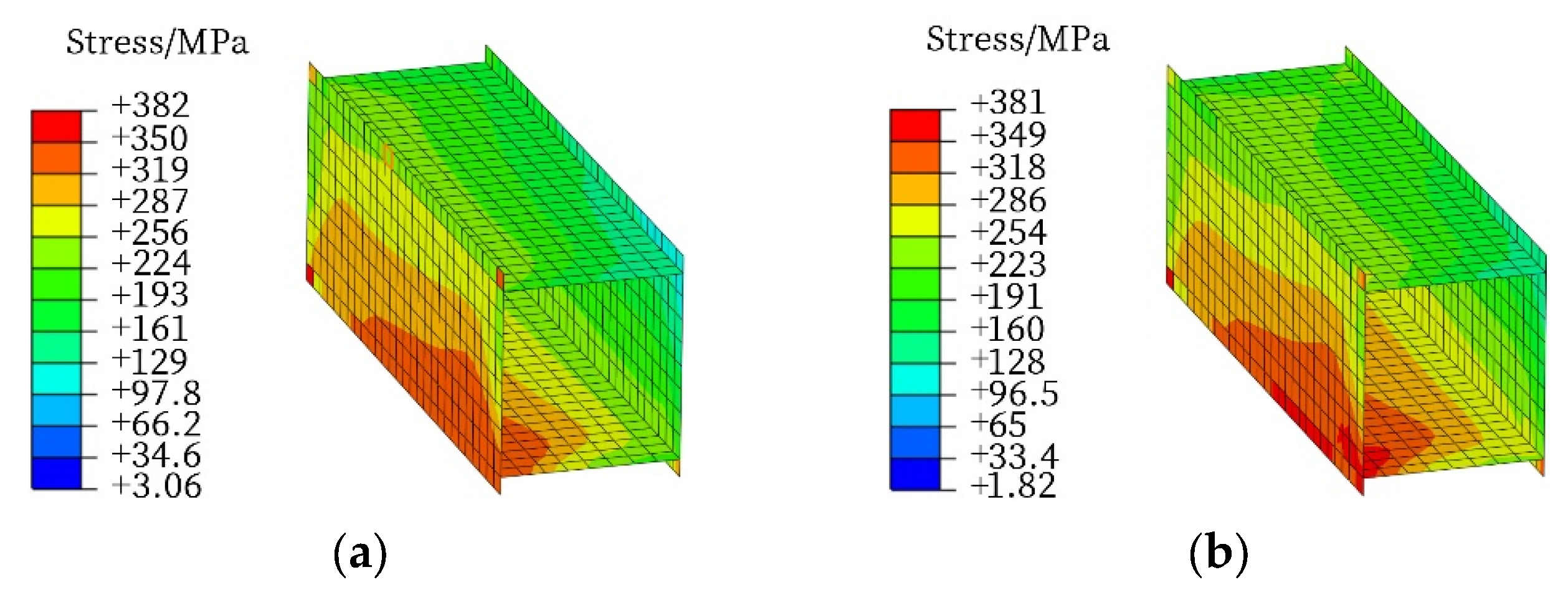
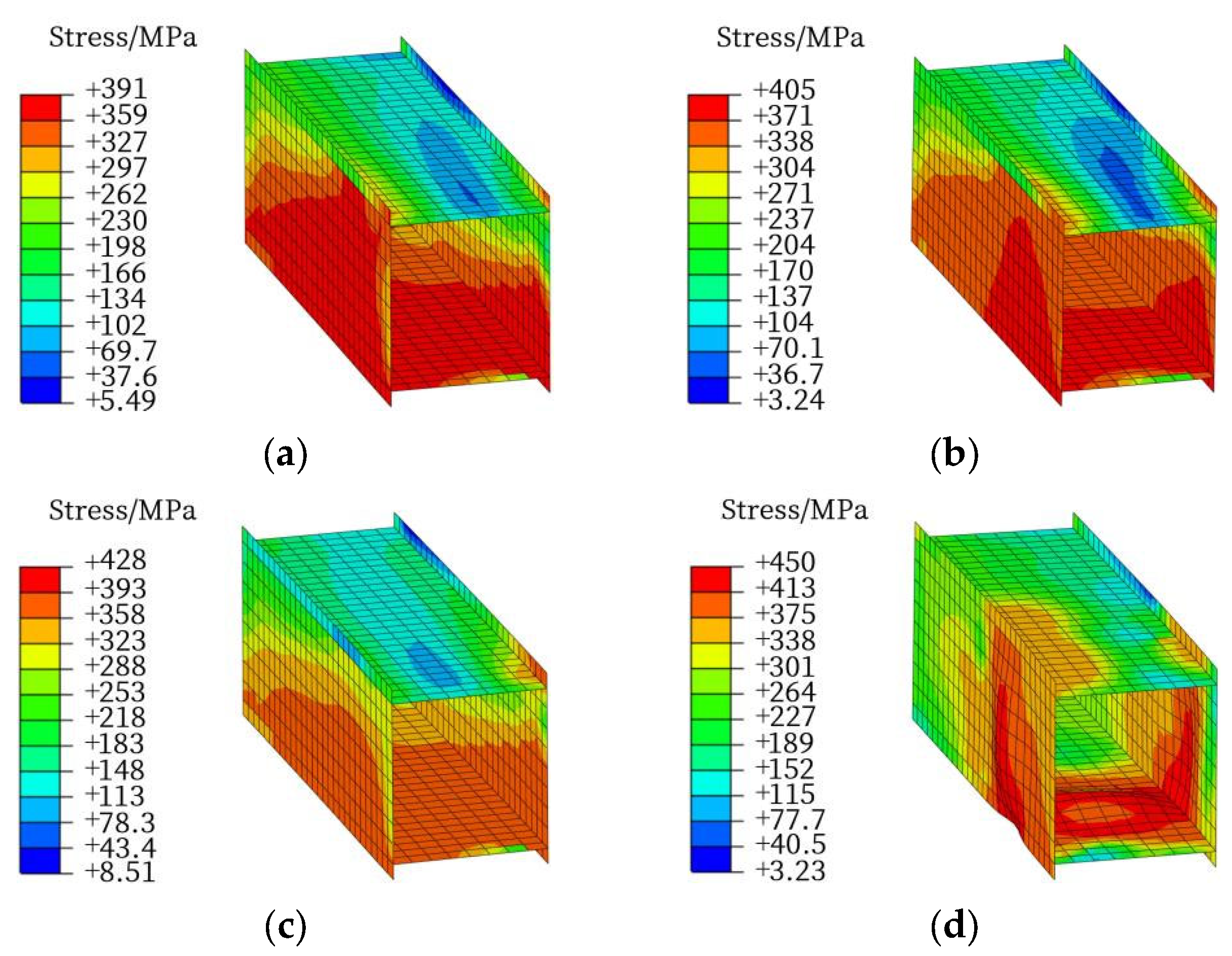
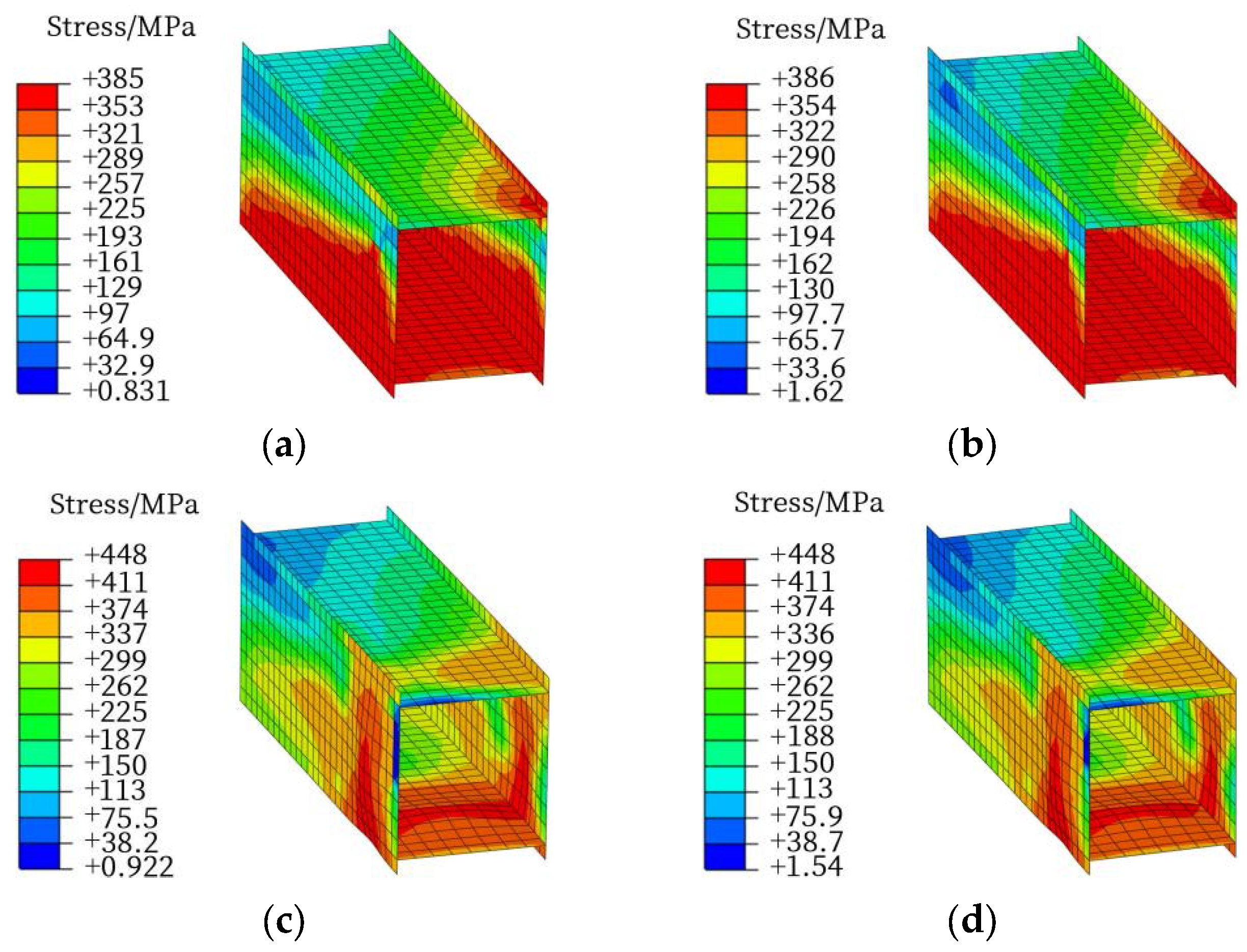
Taking models H7-10 and H7-12 as illustrative examples, in this section, the stress distribution and local deformation at the arch foot under different loading scenarios were investigated. The analysis focuses on two characteristic stages: when the arch structure attains its maximum bearing capacity and when the bearing capacity decreases to 90% of the peak value. The corresponding results are illustrated in Figure 10, Figure 11 and Figure 12.
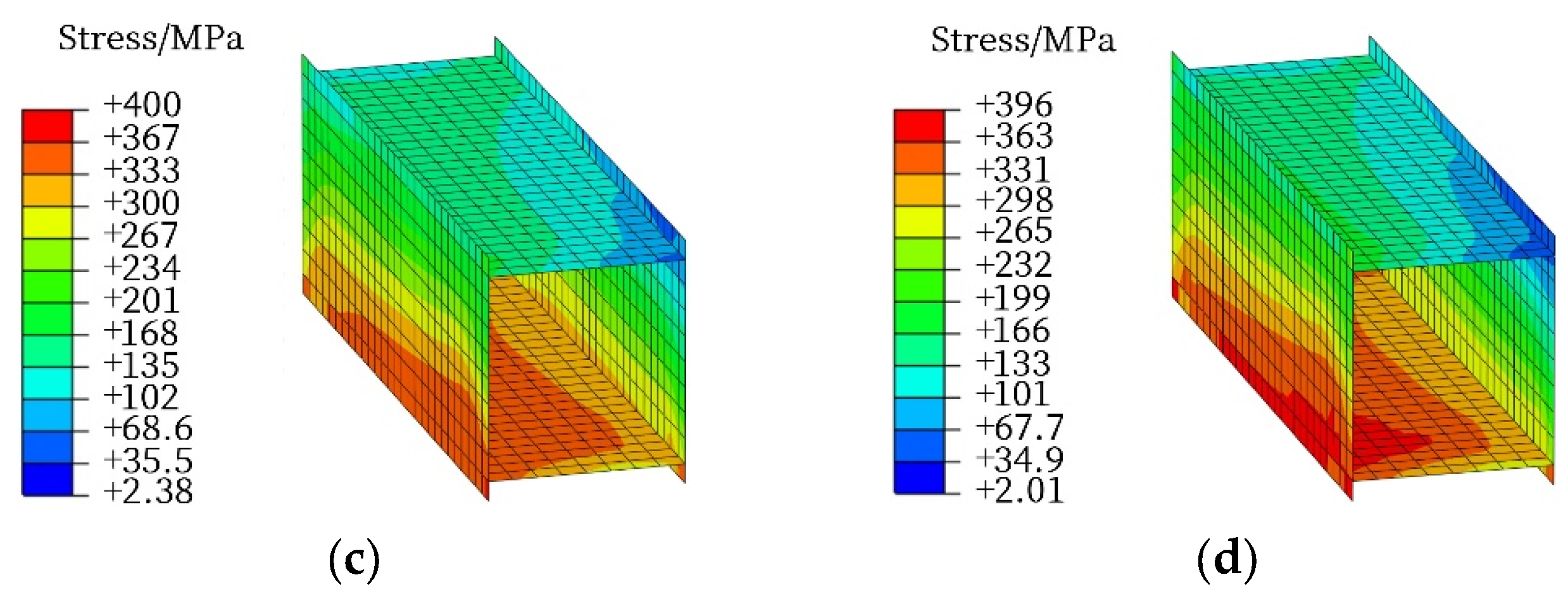
As shown in Figure 10, under loading scenario V, when reaching the ultimate bearing capacity, the maximum stress at the arch foot of models H7-V-10 and H7-V-12 is primarily concentrated in the left web and the lower flange, with peak stresses exceeding 350 MPa and 349 MPa, respectively. When the bearing capacity drops to 90% of the ultimate capacity, the maximum stress in the arch ribs at the arch foot of models H7-V-10 and H7-V-12 is mainly concentrated in the lower flange, with peak stresses exceeding 367 MPa and 363 MPa, respectively; however, local instability deformation does not occur.
As shown in Figure 11, under loading scenario V1, when reaching the ultimate bearing capacity, the maximum stress in the arch ribs at the arch foot of models H7-V1-10 and H7-V1-12 is primarily concentrated in both side webs and the lower flange, with peak stresses exceeding 359 MPa and 371 MPa, respectively. When the bearing capacity drops to 90% of the ultimate capacity, the maximum stress in the arch ribs at the arch foot of model H7-V1-10 is mainly concentrated in the left web and the lower flange, exceeding 393 MPa. In model H7-V1-12, local instability occurs in both side webs and the lower flange of the arch ribs at the arch foot, with the maximum stress exceeding 413 MPa.
As shown in Figure 12, under loading scenario V2, when reaching the ultimate bearing capacity, the maximum stress in the arch ribs at the arch foot of models H7-V2-10 and H7-V2-12 is primarily concentrated in both side webs and the lower flange, with the peak stresses exceeding 353 MPa and 354 MPa, respectively. At the moment when the bearing capacity drops to 90% of the maximum, local instability occurs in both side webs and the lower flange of the arch ribs at the arch foot in both models H7-V2-10 and H7-V2-12, with the maximum stresses exceeding 411 MPa.
In summary, an analysis of the stress distribution implies that the degree of load eccentricity directly governs the susceptibility to local instability at the arch foot. Under symmetric loading (V), a high stress concentration remains contained without triggering local buckling. In contrast, eccentric loading (V1, V2) promotes severe stress localization and out-of-plane deformation in the webs and bottom flange, leading to the earlier onset of local instability. This finding indicates that local failure at the arch foot, initiated by in-plane bending coupled with torsional effects under eccentric loads, is a critical mechanism driving global capacity degradation in basket-handle arches.

6. Conclusions

Through parametric analysis, the following conclusions are drawn on the elasto-plastic stability of steel basket-handle arches:
(1)
Load symmetry governs the bearing capacity. The capacity is highest under a symmetric vertical load (V), followed by transverse eccentric (V1) and longitudinal eccentric (V2) loading, the latter being approximately half of V.
(2)
An optimal inclination angle maximizes the capacity under symmetric loading. The initial stiffness increases monotonically with the inclination, but the ultimate capacity under V peaks at 10° and then declines.
(3)
The buckling mode depends on the load type and inclination. Under V, the mode shifts from out-of-plane to in-plane buckling when the inclination exceeds 10°. V1 consistently triggers out-of-plane buckling, while V2 triggers in-plane antisymmetric buckling.
(4)
Eccentric loading induces local instability at the arch foot. Severe stress concentration and out-of-plane deformation in the web and bottom flange precipitate early local buckling, driving global capacity reduction. Symmetric loading causes no such local failure.

Author Contributions

Conceptualization, Z.Z. and Z.W.; methodology, Z.Z.; software, Z.Z.; validation, Z.Z., Z.W. and Q.Z.; formal analysis, Z.Z.; investigation, Z.W.; resources, Z.Z.; data curation, Z.Z.; writing—original draft preparation, Z.Z.; writing—review and editing, Z.W. and J.C.; visualization, Z.Z.; supervision, Z.W.; project administration, Z.W.; funding acquisition, Z.W. All authors have read and agreed to the published version of the manuscript.

Funding

The study is supported in part by grants from the Key Tackling Project of the Department of Education of Liaoning Province (No. JYTZD2023163).

Data Availability Statement

The original contributions presented in the study are included in the article; further inquiries can be directed to the corresponding author.

Acknowledgments

The authors gratefully acknowledge the financial support provided by the relevant funding bodies.

Conflicts of Interest

The authors declare that they have no known competing financial interests or personal relationships that could have appeared to influence the work reported in this paper.

Abbreviations

The following abbreviations are used in this manuscript:
FEMsFinite Element Model
3DThree-Dimensional
FEFinite Element

References

  1. Lebet, J.-P.; Hirt, M.A. Steel Bridges: Conceptual and Structural Design of Steel and Steel-Concrete Composite Bridges; EPFL Press: Lausanne, Switzerland; CRC Press: Lausanne, Switzerland, 2013. [Google Scholar] [CrossRef]
  2. Chen, W.-F.; Duan, L. Bridge Engineering Handbook, 2nd ed.; Five Volume Set; CRC Press: Lausanne, Switzerland; Taylor & Francis Group: Boca Raton, FL, USA, 2014. [Google Scholar] [CrossRef]
  3. Sano, Y. Investigation on structural parameters of existing deck-type steel arch bridge. J. Jpn. Soc. Civ. Eng. 2011, 67, 320–325. [Google Scholar] [CrossRef]
  4. Chai, S.B.; Yang, Q.H.; Wang, X.L.; Yu, Y.L.; Zhuang, H.F. Stability analysis of long-span half-through steel box tied arch bridge during construction. Sci. Technol. Eng. 2022, 22, 8095–8102. (In Chinese) [Google Scholar]
  5. Liu, D.C.; Zhang, Z.X.; Guang, M.; Han, P.F.; Xu, L.K. Analysis and control of in-plane stability in the construction stage of kilometer-level steel box arch bridge. Highway 2025, 60, 469–475. (In Chinese) [Google Scholar]
  6. Pi, Y.L.; Bradford, M.A. In-plane strength and design of fixed steel I-section arches. Eng. Struct. 2004, 26, 291–301. [Google Scholar] [CrossRef]
  7. Pi, Y.L.; Bradford, M.A. Out-of-plane strength design of fixed steel I-section arches. J. Struct. Eng. 2005, 131, 560–568. [Google Scholar] [CrossRef]
  8. Guo, Y.L.; Zhao, S.Y.; Pi, Y.L.; Bradford, M.A.; Dou, C. An experimental study on out-of-plane inelastic buckling strength of fixed steel arches. Eng. Struct. 2015, 98, 118–127. [Google Scholar] [CrossRef]
  9. Dou, C.; Guo, Y.L.; Zhao, S.Y.; Pi, Y.L. Experimental investigation into flexural-torsional ultimate resistance of steel circular arches. J. Struct. Eng. 2015, 141, 04015006. [Google Scholar] [CrossRef]
  10. Japan Bridge Association Inc. Steel Bridge; Sanyo Media Co., Ltd.: Tokyo, Japan, 2024. (In Japanese) [Google Scholar]
  11. Chen, B.C.; Liu, J.P. Review of construction and technology development of arch bridges in the world. J. Traffic Transp. Eng. 2020, 20, 27–41. [Google Scholar] [CrossRef]
  12. Hu, X.; Xie, X.; Tang, Z.; Shen, Y.; Wu, P.; Song, L. Case study on stability performance of asymmetric steel arch bridge with inclined arch ribs. Steel Compos. Struct. 2015, 18, 273–288. [Google Scholar] [CrossRef]
  13. Liu, A.R.; Huang, Y.H.; Fu, J.Y.; Yu, Q.C.; Rao, R. Experimental research on stable ultimate bearing capacity of leaning-type arch rib systems. J. Constr. Steel Res. 2015, 114, 281–292. [Google Scholar] [CrossRef]
  14. Liu, A.; Lu, H.; Fu, J.; Pi, Y.L.; Huang, Y.; Li, J.; Ma, Y. Analytical and experimental studies on out-of-plane dynamic instability of shallow circular arch based on parametric resonance. Nonlinear Dyn. 2017, 87, 677–694. [Google Scholar] [CrossRef]
  15. Jiang, Z.Q.; Xiao, R.C.; Song, C.L.; Sun, B.; Tong, S.H.; Ma, Y. An analytical method for out-of-plane stability assessment of network arch bridges. Thin Walled Struct. 2024, 204, 112289. [Google Scholar] [CrossRef]
  16. Sun, J.B.; Chen, S.Y.; Wang, Z.F.; Sui, W.N.; Zhang, Q. Study of the impact of varying inclination angles of arch ribs on the seismic behavior of half-through steel basket-handle arch bridge. Buildings 2024, 14, 794. [Google Scholar] [CrossRef]
  17. Zhao, W.J.; Liu, H.; Wang, Z.F. Dynamic characteristic and stability analysis of small rise-span ratio steel deck-type basket arch bridge. J. Shenyang Jianzhu Univ. Nat. Sci. 2019, 35, 194–201. (In Chinese) [Google Scholar]
  18. Wang, Z.F.; Tan, L.X.; Wu, J.X.; Song, Y. Research of elastic plastic mechanical properties of steel basket handle arch ribs with box section under horizontal cyclic loading. J. Shenyang Jianzhu Univ. Nat. Sci. 2024, 40, 131–140. (In Chinese) [Google Scholar]
  19. EN 1993-2:2006; Eurocode 3: Design of Steel Structures—Part 2: Steel Bridges. European Committee for Standardization/Comité Européen de Normalisation: Brussels, Belgium, 2009.
  20. Ren, H.; Fu, Z.; Ji, B.; Zhang, Z. Evaluation of stability behavior of the steel truss-arch composite structure. Structures 2023, 57, 105240. [Google Scholar] [CrossRef]
  21. JTG D64-2015; Industrial Standards of the People’s Republic of China. Specifications for Design of Highway Steel Bridges. China Communications Publishing & Media Management Co., Ltd.: Beijing, China, 2015. (In Chinese)
  22. Japan Road Association. Specifications for Highway Bridges, Part II. Steel Bridge; Maruzen Co., Ltd.: Tokyo, Japan, 2018. [Google Scholar]
  23. Sakata, T.; Sakimoto, T. Experimental study on the out-of-plane buckling strength of steel arches with open cross section. Struct. Eng. Earthq. Eng. JSCE 1990, 416, 101–112. (In Japanese) [Google Scholar] [CrossRef] [PubMed]
  24. Sakimoto, T.; Yamao, T.; Komatsu, S. Experimental study on the ultimate strength of steel arches. Proc. Jpn. Soc. Civ. Eng. 1979, 286, 136–149. [Google Scholar] [CrossRef] [PubMed][Green Version]
  25. Sakimoto, T.; Komatsu, S. Ultimate strength formula for steel arches. J. Struct. Eng. ASCE 1983, 109, 613–627. [Google Scholar] [CrossRef]
Figure 1. The steel basket-handle arch rib structure with box section (unit: mm). (a) 3D schematic diagram. (b) Elevation. (c) Box section of arch ribs. (d) Box section of lateral braces.
Buildings 16 01013 g001
Figure 2. Forms of vertical loading and loading scenarios. (a) Method of vertical load application. (b) Uniformly distributed vertical loads V. (c) Transversely eccentric vertical loads V1. (d) Longitudinally eccentric vertical loads V2.
Buildings 16 01013 g002
Figure 3. FEM of the steel arch structure with a box section.
Buildings 16 01013 g003
Figure 4. Comparison of specimen deformation tests and FEM. (a) Specimen 1 [24]. (b) Specimen 2 [24].
Buildings 16 01013 g004
Figure 5. Effect of the inclination angle on bearing capacity–lateral horizontal displacement curves of the vault. (a) Uniformly distributed vertical loads V. (b) Transversely eccentric vertical loads V1. (c) Longitudinally eccentric vertical loads V2.
Buildings 16 01013 g005
Figure 6. Effect of load cases on bearing capacity–lateral horizontal displacement curves of the vault. (a) Inclination angle α = 4°. (b) Inclination angle α = 8°. (c) Inclination angle α = 12°.
Buildings 16 01013 g006
Figure 7. Instability modes of the arch structure under loading scenario V (deformation scaling factor: 3). (a) H7-V-4 (out-of-plane instability is predominant); (b) H7-V-12 (in-plane instability is predominant).
Buildings 16 01013 g007
Figure 8. Instability modes of the arch structure under loading scenario V1 (deformation scaling factor: 3). (a) H7-V1-4 (out-of-plane instability is predominant); (b) H7-V1-12 (out-of-plane instability is predominant).
Buildings 16 01013 g008
Figure 9. Instability modes of the arch structure under loading scenario V2 (deformation scaling factor: 3). (a) H7-V2-4 (Out-of-plane instability is predominant); (b) H7-V2-12 (Out-of-plane instability is predominant).
Buildings 16 01013 g009
Figure 10. Stress contours at the arch foot under loading scenario V. (a) H7-V-10 (at maximum bearing capacity); (b) H7-V-12 (at maximum bearing capacity); (c) H7-V-10 (at 90% of the maximum bearing capacity); (d) H7-V-12 (at 90% of the maximum bearing capacity). Note: Global instability: Refers to the overall in-plane or out-of-plane buckling of the arch structure, characterized by large-scale deformation of the arch ribs. Local instability: Refers to excessive lateral deformation of plate components (flanges, webs) within a member cross-section under compressive axial stress, manifested as local bulging or denting of the plates.
Buildings 16 01013 g010aBuildings 16 01013 g010b
Figure 11. Stress contours at the arch foot under loading scenario V1. (a) H7-V1-10 (at maximum bearing capacity); (b) H7-V1-12 (at maximum bearing capacity); (c) H7-V1-10 (at 90% of the maximum bearing capacity); (d) H7-V1-12 (at 90% of the maximum bearing capacity).
Buildings 16 01013 g011
Figure 12. Stress contours of the arch foot under loading scenario V2. (a) H7-V2-10 at (maximum bearing capacity); (b) H7-V2-12 (at maximum bearing capacity); (c) H7-V2-10 (at 90% of the maximum bearing capacity); (d) H7-V2-12 (at 90% of the maximum bearing capacity).
Buildings 16 01013 g012
Table 1. Design parameters of the steel box basket-handle arch structure and loading scenarios.
Model NumberLoading ScenarioInclination Angle αModel NumberLoading ScenarioInclination Angle αModel NumberLoading ScenarioInclination Angle α
H7-V-0V0H7-V1-0V10H7-V2-0V20
H7-V-1V1H7-V1-1V11H7-V2-1V21
H7-V-2V2H7-V1-2V12H7-V2-2V22
H7-V-3V3H7-V1-3V13H7-V2-3V23
H7-V-4V4H7-V1-4V14H7-V2-4V24
H7-V-5V5H7-V1-5V15H7-V2-5V25
H7-V-6V6H7-V1-6V16H7-V2-6V26
H7-V-7V7H7-V1-7V17H7-V2-7V27
H7-V-8V8H7-V1-8V18H7-V2-8V28
H7-V-9V9H7-V1-9V19H7-V2-9V29
H7-V-10V10H7-V1-10V110H7-V2-10V210
H7-V-11V11H7-V1-11V111H7-V2-11V211
H7-V-12V12H7-V1-12V112H7-V2-12V212
H7-V-13V13H7-V1-13V113H7-V2-13V213
H7-V-14V14H7-V1-14V114H7-V2-14V214
H7-V-15V15H7-V1-15V115H7-V2-15V215
Table 2. Mechanical properties of material.
MemberYoung’s Modulus E/GPaYield Strength σy/MPaUltimate Strength σu/MPaPoisson’s Ratio μ
Arch ribs218364.0449.80.3
Cross braces218364.0449.80.3
Table 3. Geometric dimensions of the test specimen and comparison of ultimate bearing capacity test and FEM results.
Specimen NumberSpan/mmSpacing of Arch Ribs/mmRise/mmSection Size of Arch Ribs a × b/mmSection Size of Cross Braces a × b/mmNumber of Cross BracesUltimate Bearing CapacityFS/FT/%
FEM FS/kNTest FT/kN
1280015056050 × 5037 × 93559.2546.1102.4
2280015056050 × 5037 × 97487.3508.296.9
Table 4. Instability mode, ultimate bearing capacity and lateral displacement of the arch vault corresponding to the ultimate bearing capacity of the arch structure.
Loading ScenarioItemα = 0°α = 1°α = 2°α = 3°α = 4°α = 5°α = 6°α = 7°
VFu/kN45,582.847,281.449,072.250,919.052,637.154,017.154,887.755,406.8
δu/mm393.1361.2329.2309.0276.8256.6212.6179.7
Buckling ModeOut-of-plane
V1Fu/kN39,681.643,235.445,356.546,025.144,331.643,430.043,092.543,339.8
δu/mm445.4256.934.0−350.3−386.2−395.7−397.5−418.7
Buckling ModeOut-of-plane
V2Fu/kN28,245.928,244.928,235.828,216.728,190.428,156.828,116.328,069.0
δu/mm89.578.768.970.552.044.738.232.5
Buckling ModeIn-plane
Loading ScenarioItemα = 8°α = 9°α = 10°α = 11°α = 12°α = 13°α = 14°α = 15°
VFu/kN55,707.155,855.455,883.955,832.455,721.955,560.455,362.755,138.5
δu/mm157.4126.3102.282.268.054.953.547.5
Buckling ModeOut-of-planeIn-plane
V1Fu/kN44,134.145,485.247,332.548,743.749,861.750,132.050,401.450,778.7
δu/mm−404.2−401.3−376.0−269.8−182.5−121.4−83.3−54.4
Buckling ModeOut-of-plane
V2Fu/kN28,014.427,951.027,881.027,804.527,721.827,636.827,545.827,447.6
δu/mm27.122.718.515.212.39.67.86.6
Buckling ModeIn-plane
Note: In-plane: Buckling of the arch structure occurring within its own plane, characterized primarily by vertical deflection of the arch axis with minimal lateral displacement. It is typically associated with axial compression and in-plane bending moments. Out-of-plane: Buckling of the arch structure occurring perpendicular to its own plane, characterized primarily by lateral bending and torsional deformation. It is typically related to the lateral stiffness and transverse restraints of the structure.
Disclaimer/Publisher’s Note: The statements, opinions and data contained in all publications are solely those of the individual author(s) and contributor(s) and not of MDPI and/or the editor(s). MDPI and/or the editor(s) disclaim responsibility for any injury to people or property resulting from any ideas, methods, instructions or products referred to in the content.