Article

Free Vibration and Static Behavior of Bio-Inspired Helicoidal Composite Spherical Caps on Elastic Foundations Applying a 3D Finite Element Method


1
Faculty of Mechanical Engineering, K.N. Toosi University of Technology, Tehran 19991-43344, Iran
2
Department of Mechanical Engineering, Islamic Azad University, North Tehran Branch, Tehran 16511-53311, Iran
3
Advanced Research and Development Center, LIPS Research Foundation, European International University, 75018 Paris, France
*
Authors to whom correspondence should be addressed.
Buildings 2026, 16(2), 273; https://doi.org/10.3390/buildings16020273
Submission received: 28 September 2025 / Revised: 19 October 2025 / Accepted: 23 October 2025 / Published: 8 January 2026
(This article belongs to the Special Issue Applications of Computational Methods in Structural Engineering)

Abstract

Spherical caps exploit their intrinsic curvature to achieve efficient stress distribution, delivering exceptional strength-to-weight ratios. This advantage renders them indispensable for aerospace systems, pressurized containers, architectural domes, and structures operating in extreme environments, such as deep-sea or nuclear containment. Their superior load-bearing capacity enables diverse applications, including satellite casings and high-pressure vessels. Meticulous optimization of geometric parameters and material selection ensures robustness in demanding scenarios. Given their significance, this study examines the natural frequency and static response of bio-inspired helicoidally laminated carbon fiber–reinforced polymer matrix composite spherical panels surrounded by Winkler elastic foundation support. Utilizing a 3D elasticity approach and the finite element method (FEM), the governing equations of motion are derived via Hamilton’s Principle. The study compares five helicoidal stacking configurations—recursive, exponential, linear, semicircular, and Fibonacci—with traditional laminate designs, including cross-ply, quasi-isotropic, and unidirectional arrangements. Parametric analyses explore the influence of lamination patterns, number of plies, panel thickness, support rigidity, polar angles, and edge constraints on natural frequencies, static deflections, and stress distributions. The analysis reveals that the quasi-isotropic (QI) laminate configuration yields optimal vibrational performance, attaining the highest fundamental frequency. In contrast, the cross-ply (CP) laminate demonstrates marginally best static performance, exhibiting minimal deflection. The unidirectional (UD) laminate consistently shows the poorest performance across both static and dynamic metrics. These investigations reveal stress transfer mechanisms across layers and elucidate vibration and bending behaviors in laminated spherical shells. Crucially, the results underscore the ability of helicoidal arrangements in augmenting mechanical and structural performance in engineering applications.

1. Introduction

Spherical shells are curved structural elements that form segments of a complete sphere and are extensively implemented in mechanical and industrial contexts owing to their outstanding load-bearing capability, favorable stress distribution, and high structural efficiency. Characterized by their geometric curvature, these shells efficiently transfer applied loads—such as internal or external pressure, thermal gradients, and mechanical forces—primarily through membrane stresses, resulting in a high strength-to-weight ratio and reduced material consumption while maintaining structural integrity. This inherent stiffness and resistance to both compressive and tensile stresses make them particularly suitable for pressurized enclosures and containment structures, in which uniform stress distribution and minimal deformation are critical. In engineering industries, spherical shells are widely employed in aerospace systems (e.g., rocket nose cones and satellite fairings), chemical processing equipment (including reactors, centrifuges and boilers), offshore platforms, submarine domes, and civil infrastructure such as architectural domes, water towers, and large-span roofs. Their aerodynamic and hydrodynamic properties also contribute to improved performance in fluid–structure interaction scenarios. A significant feature of these shells is their adaptability in modular and prefabricated construction, enabling the realization of large-span structures with minimal internal support. Owing to their versatility, durability, and superior load management characteristics, spherical shells remain a cornerstone in modern engineering design, playing a vital role in ensuring safety, efficiency, and innovation across a wide spectrum of industrial sectors.
Owing to their broad applicability, researchers have extensively examined the mechanical behavior of these spherical shells under diverse conditions. Iarriccio et al. [1] explored nonlinear asymmetric vibrations in shallow spherical caps under dynamic pressure, revealing that even axisymmetric loads can induce chaotic responses, with sudden shifts between dynamic regimes. This underscores potential instability risks in pressure-critical applications. Shen et al. [2] analyzed free vibrations in functionally graded (FG) porous spherical caps reinforced with graphene platelets, employing 3D finite element methods and Hamilton’s principle. Meanwhile, Nam et al. [3] demonstrated that sandwich-structured FG-GPL RC (graphene platelet-reinforced composite) spherical caps exhibit superior thermomechanical stability compared to other curvatures (e.g., ellipsoids, paraboloids), owing to their uniform curvature and predictable failure modes. Further investigations into dynamic responses include Haboussi et al. [4], who studied nonlinear axisymmetric buckling in porous nanocomposite spherical caps using shear deformation theory, identifying optimal shallowness for stability. Bagheri et al. [5] examined free vibrations in FGM hermetic capsules with spherical end caps, combining Donnell shell theory with the generalized differential quadrature (GDQ) method. Ubamanyu et al. [6] highlighted the unique buckling resistance of near-perfect spherical shells, which localize deformation at the pole, unlike other geometries prone to boundary-driven collapse. Additionally, Vu et al. [7] developed a semi-analytical model for electro-thermo-mechanical responses in FG-GPL RC spherical shells, integrating Lagrange equations and Runge–Kutta methods. Lastly, Iarriccio et al. [8] revisited nonlinear dynamics in isotropic shallow caps, demonstrating how static and dynamic pressure interactions can trigger asymmetric instabilities, even in symmetric configurations. Collectively, these studies underscore the complexity and advantages of spherical shells while highlighting critical design considerations for industrial applications.
Bio-inspired helicoidal laminated composites are a transformative class of engineered materials that replicate the hierarchical, twisted plywood-like microstructures observed in natural systems, such as mollusk shells [9], beetle forewings [10], plant cell walls [11], and the helicoidal exoskeletal features of grasshoppers and locusts (Insecta) [12,13]. These composites achieve exceptional toughness, damage tolerance, and impact resistance by mimicking the Bouligand structure—a helicoidal arrangement of unidirectional fiber layers where each successive lamina is incrementally rotated. This design disrupts crack propagation and enhances energy dissipation through mechanisms like fiber bridging, matrix shearing, and delamination deflection, yielding superior fracture toughness, multi-directional load-bearing capacity, and impact resistance, even at low fiber volume fractions [14]. A defining advantage of helicoidal laminates is their ability to uniformly distribute stress, mitigating localized concentrations and delaying catastrophic failure under dynamic or high-strain-rate loading. A striking example is the Odontodactylus scyllarus (peacock mantis shrimp), whose dactyl club exhibits extraordinary impact resistance [15,16]. This appendage withstands cyclic forces thousands of times its body weight due to its helicoidal fibrous microstructure [17], exemplifying nature’s optimization for extreme loading conditions.
Beyond mechanical performance, helicoidal composites can be tailored for multifunctionality, incorporating impact absorption, vibration damping, or even structural health monitoring. By merging biological principles with engineering innovation, these composites not only surpass traditional materials in performance but also align with sustainable design through nature-inspired optimization [14,18].
The practical implementation of the bio-inspired helicoidal laminates analyzed in this study is increasingly viable due to advancements in composite manufacturing technologies. The structural efficacy of these designs hinges on precise, strategic layering of fibers at varying orientations, achievable through both conventional and advanced fabrication methods. Traditional techniques, such as manual lay-up and vacuum bagging, have been successfully employed, as demonstrated by Ginzburg et al. [19], who utilized unidirectional carbon fiber epoxy prepreg to fabricate helicoidal specimens. Concurrently, innovations in automated fiber placement (AFP), robotic deposition, and additive manufacturing have revolutionized the production of intricate helicoidal architectures. While conventional 3D printing materials like plastics and metals often exhibit limited mechanical properties for replicating the superior performance of helicoidal configurations [14], the integration of advanced materials—such as hydrogels, biopolymers, and ceramics—enables the creation of composites with enhanced strength, toughness, and fracture resistance [20]. Furthermore, cutting-edge technologies, including digital light processing (DLP), two-photon polymerization (2PP), and inkjet printing [21], have overcome previous limitations, offering improved resolution, precision, and production efficiency [22]. These advancements significantly bolster the applicability of helicoidal composites across high-performance sectors, including aerospace, defense, automotive, and biomedical industries.
Complex aerospace and mechanical structures are frequently modeled as assemblies of plates (e.g., flat plates, annular disks), curved shells/panels (e.g., toroidal, spherical, cylindrical, and conical shells), and beams to simplify and assist analytical and numerical investigations of their static, dynamic, vibrational, and buckling behavior [23]. Given the demonstrated advantages of bio-inspired helicoidal laminates—including enhanced damage tolerance, impact resistance, and stress distribution—researchers have extensively studied their influence on the mechanical performance of plate and shell structures. Recent studies highlight the superior properties of helicoidal laminates in plate configurations. Melaibari et al. [24] demonstrated that bio-inspired laminates with controlled artificial delaminations exhibit pseudo-ductile, metal-like failure, increasing strength by 11.9%, failure strain by 208%, and energy absorption by 288.1% compared to conventional designs. Lu et al. [25] proposed hybrid helicoidal layups, achieving 35–50% higher buckling resistance and 40–60% improved thermal stability. Further investigations reveal their exceptional impact performance. Baakeel et al. [26] indicated that curved helicoidal plates significantly lessen impact force and deflection under low-velocity impacts, while Gowda et al. [27] developed bio-composite armor with helicoidal hemp/basalt/polyurethane structures, noting enhanced ballistic resistance due to spiral stress distribution. For dynamic loading, Do et al. [28] employed higher-order shear deformation theory (HSDT) and isogeometric analysis (IGA) to confirm improved dissipative damping behavior in helicoidally laminated plates under explosive loads. Buckling and vibration characteristics have also been rigorously examined. Garg et al. [29] identified superior buckling resistance in helicoidal architectures via finite element analysis, whereas Saurabh et al. [30] linked stacking sequences to nonlinear free vibration frequencies and bending behavior. Mohamed et al. [31] combined FSDT with the differential quadrature method (DQM) to optimize fiber orientations for stability and vibration resistance. Helicoidal laminates excel under extreme conditions. Garg et al. [32] demonstrated their reduced damage under high-velocity projectile impacts in comparison with cross-ply and quasi-isotropic laminates using ABAQUS simulations. Mohamed et al. [33] further analyzed dynamic stability under variable axial loads, employing FSDT and 2D-DQM to validate their robustness.
Despite growing interest in bio-inspired structures, few studies have explored the potential utility of helical structural features in annular plates. Garg et al. [34] utilized a hybrid IGA–machine learning framework to study free vibration in corrugated annular and flat plates, revealing that helicoidal laminate configurations improve structural response. Further, Bayat et al. [18] applied FSDT to bio-inspired helicoidal annular sector plates, revealing that unidirectional (UD) laminates offer superior free vibration performance, whereas helicoidal semicircular (HS) configurations exhibit the lowest stiffness. Expanding on this, Garg et al. [35] utilized IGA coupled with refined plate theory (RPT) to analyze vibration responses of helicoidal laminated composites in square and annular plates with circular cutouts, highlighting the method’s efficacy in modeling complex geometries.
Research on helicoidally laminated beam-type structures remains limited, despite their promising mechanical properties. Karamanli et al. [36] employed the Ritz method to analyze bio-inspired helicoidal laminated composite (BIHLC) beams, establishing an analytical framework for bending, buckling, and vibration. Their findings highlighted coupled axial-stretching-bending deformations, with performance heavily dependent on fiber reinforcement, rotation angles, and layer count. Complementing this, Yang et al. [37] numerically assessed helicoidal structures under dynamic loads, showing that Bouligand-type architectures excel in blast mitigation by attenuating stress waves and reducing force transmission. Further advancing the field, Karamanli et al. [38] conducted a multi-theory analysis of curved helicoidal beams, comparing Classical, First-Order, Higher-Order, and Quasi-3D theories. Their results indicated that among the layups evaluated, the recursive and exponential designs demonstrated superior stiffness, as evidenced by their significantly reduced deflections. Additionally, normal stress increased with fiber angles, while shear stress decreased, introducing unique interfacial coupling absent in straight beams. Finally, Almitani et al. [39] addressed the buckling and bending of bio-inspired laminated beams by developing exact analytical solutions, confirming that layup configurations critically influence nonlinear structural responses. Together, these studies underscore the versatility of helicoidal beams but also reveal a need for further exploration of their full potential.
Initially, bio-inspired helicoidal lamination was considered applicable only to flat structures; however, subsequent research has demonstrated its significant advantages for curved shell elements. Khotjanta et al. [40] analytically identified optimal fiber interply angles that minimize interlaminar stresses of helicoidally laminated curved panels. Expanding on this, Garg et al. [41] employed a bootstrap-based Gaussian Process Regression (GPR) model to assess stochastic free vibration in various types of shells under thermal loads, revealing that ply orientation uncertainties critically influence vibrational behavior, particularly at elevated temperatures and noise levels. Further, Thu et al. [42] examined the transient blast response of curved helicoidal laminated panels using an improved FSDT and IGA, demonstrating that stiffness varies with number of plies and stacking pattern. Garg et al. [43] advanced this field by combining IGA with HSDT in a machine learning-assisted framework, proving that helicoidal laminates surpass cross-ply designs in dynamic performance, with natural frequencies increasing at larger inter-ply angles. Kalhori et al. [44] systematically evaluated buckling in helicoidal cylindrical shells via 3D elasticity theory and finite element analysis, showing Fibonacci Helicoidal laminates excel in axial buckling resistance, whereas Helicoidal Semicircular patterns dominate in torsional buckling—both outperforming conventional unidirectional and quasi-isotropic designs. Notably, Helicoidal Recursive HR (β = 1) consistently exhibited inferior performance. Complementing these findings, Garg et al. [45] utilized multi-output GPR and Monte Carlo simulations to establish that outer-layer ply orientations disproportionately impact vibration frequencies in simply supported and clamped cylindrical shells, while cantilevered shells exhibit inverse sensitivity to inner-layer variations. Collectively, these studies underscore the superior adaptability of helicoidal laminates in curved shell applications.
While extensive research has explored various aspects of bio-inspired helicoidally laminated structures, no prior study has investigated the natural frequency or static response of helicoidal laminated composite spherical shells—a critical gap this work addresses. Given their potential in aerospace and marine applications, where spherical caps are frequently exposed to various of loads, understanding their vibrational and static behavior with helicoidal lamination is essential. As a novel contribution, this study examines, for the first time, the free vibration and static response of spherical shells composed of T300/5208 graphite/epoxy CFRP, supported by a Winkler elastic foundation. Unlike most spherical shell analyses relying on equivalent single-layer (ESL) theories, we employ 3D linear elasticity theory and Hamilton’s principle, solved via the classical FEM, to capture thickness-stretching effects and achieve higher accuracy. Various helicoidal stacking sequences are compared against traditional well-known lay-up designs. Parametric studies assess the influence of lamination patterns, number of plies, polar angles, sphere thickness, support rigidity, and edge constraints on natural frequencies, static deflections, and stress distributions. Collectively, these analyses provide a rigorous scientific foundation for optimizing the design of helicoidally laminated spherical shells in engineering applications.
As mentioned earlier, this study employs a three-dimensional linear elasticity framework, assuming perfect interlaminar bonding, to analyze the static and vibrational responses of bio-inspired helicoidal spherical caps. While this methodology effectively characterizes global stiffness, through-thickness stress distributions, and modal characteristics, it is inherently limited in its capacity to model nonlinear failure mechanisms. Specifically, the model does not incorporate failure criteria and, due to the perfect bonding assumption, cannot predict critical failure modes such as interlaminar delamination or interfacial debonding, which are prevalent under extreme or cyclic loading conditions. To address these limitations, subsequent research will integrate nonlinear material models, cohesive zone elements, and progressive damage algorithms to simulate the onset and propagation of delamination.

2. Problem Modeling

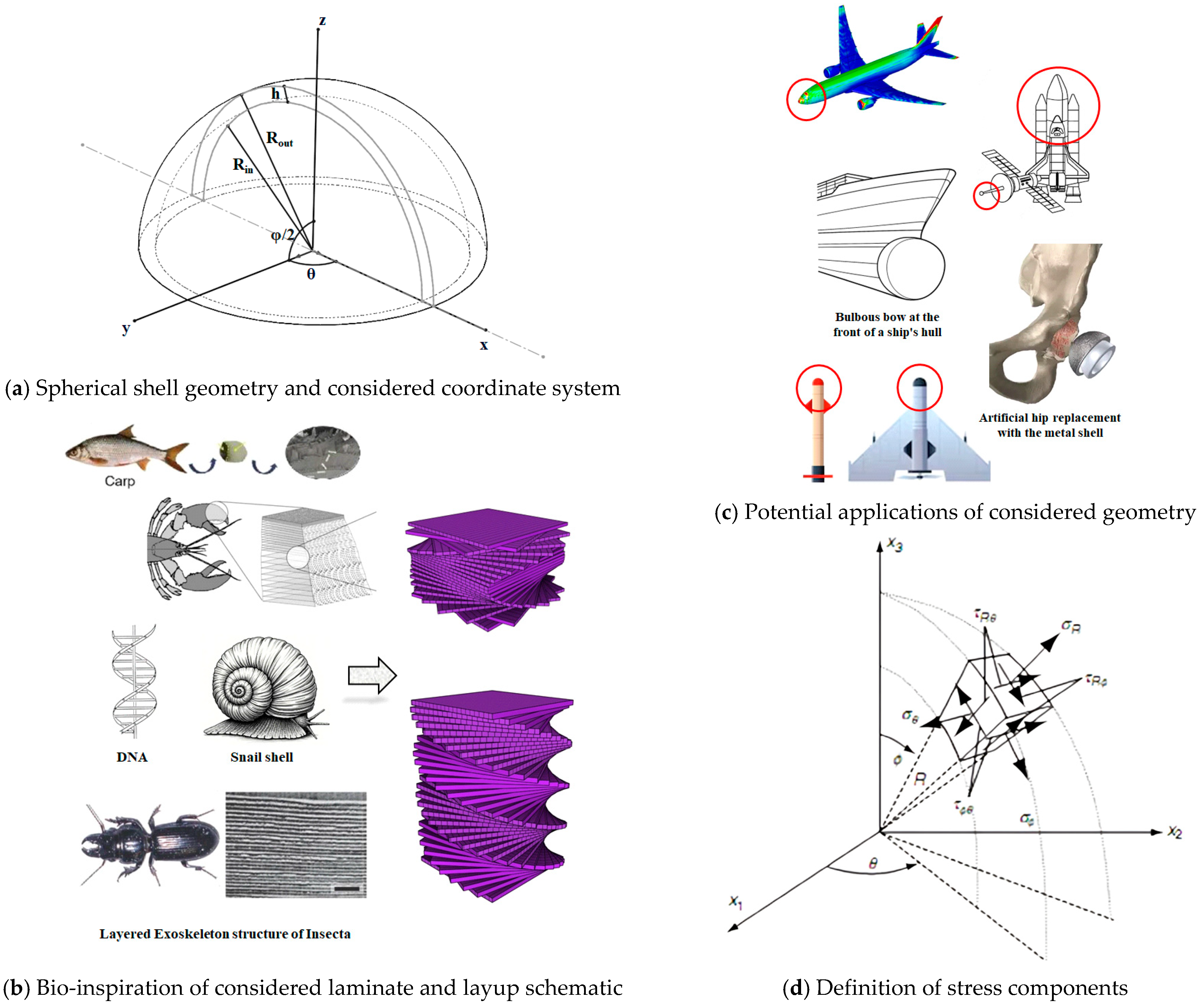
Consider a spherical cap of uniform thickness h and mean radius R a v e , with outer and inner radii denoted as R o u t = b and R i n = a , respectively. The geometric description of the shell is based on a spherical coordinate system ( r ,   θ ,   φ ) , with r corresponding to the radial component, θ ( 0 θ 2 π ) is the azimuthal angular component in the xy-plane, and φ ( 0   φ   π / 2 ) is the polar angle (see Figure 1). The shell comprises N o L orthotropic layers, each with a constant thickness t . The structure rests on a Winkler elastic support, characterized by a modulus k w , modeled as an independent spring system. For static bending and stress analysis, the shell is subjected to a uniform external normal pressure applied to its outer surface; while no external load is required for free vibration studies.
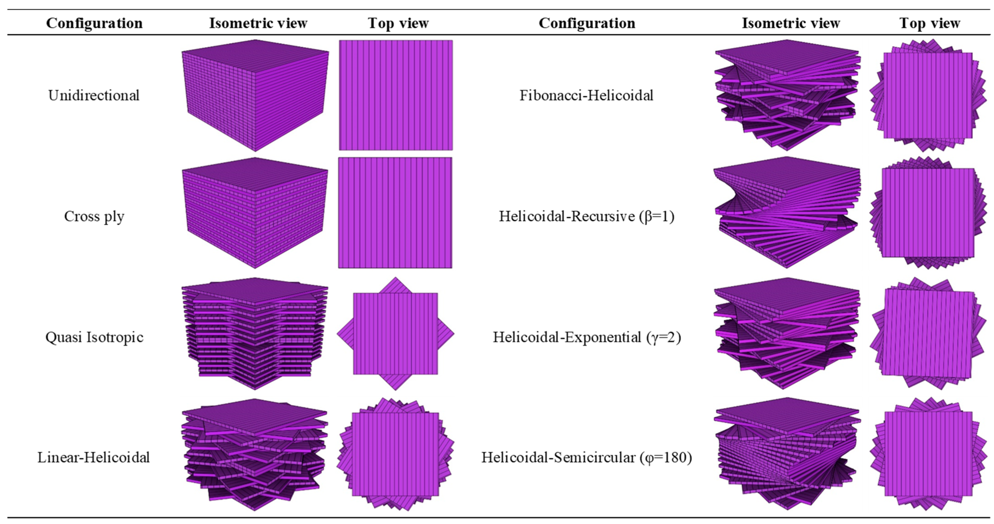
As shown in Figure 2, eight distinct lamination stacking sequences are examined across the spherical cap’s thickness, comprising five helicoidal patterns and three conventional stacking sequences. Table 1 outlines the analytical relationships, configuration-specific characteristics, and helicoidal stacking protocols for all considered layups.
The helicoidal stacking sequences are characterized by parametric variables β, γ, and ϕ, which prescribe the progressive fiber rotation angles for the Recursive, Exponential, and Semicircular configurations, respectively. These parameters, detailed in Table 1, govern the interlayer orientation increments, enabling tailored anisotropic responses that emulate bio-inspired structural efficiencies.
The exponential (HE) and semicircular (HS) patterns exhibit nonlinear through-thickness lamination schemes governed by their nonlinear orientation formulations. In contrast, all other layups utilize simpler, linearly defined fiber orientations. Let φ be the maximum rotation angle (imposed on the N o L 2 -th ply) in the HS configuration; the parameter χ then follows from φ and the total number of plies.
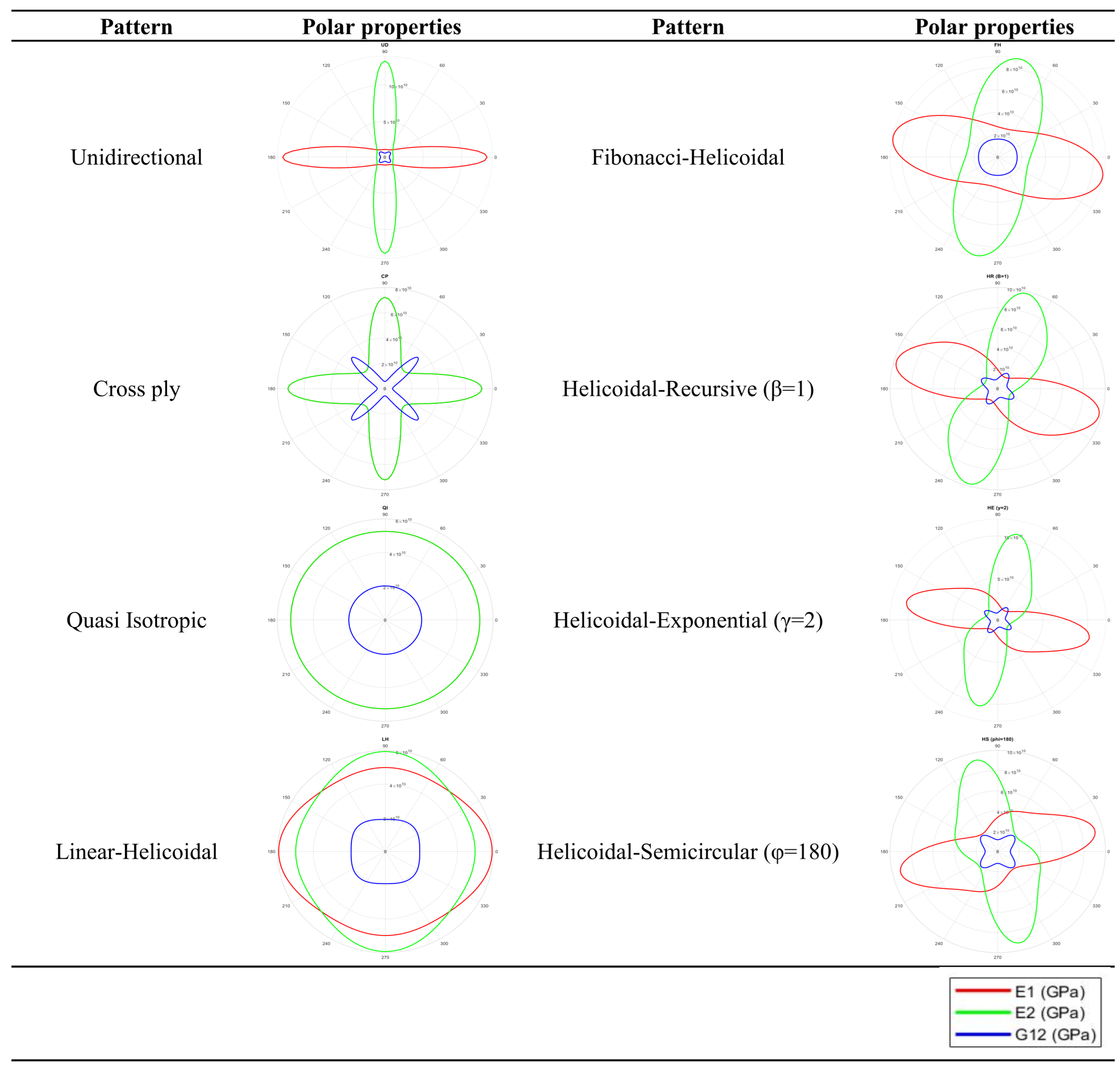
The study employs plane-orthotropic T300/5208 Carbon/Epoxy, with material properties detailed in Table 2. To highlight the in-plane orientational anisotropy introduced by bio-inspired stacking sequences, the angular variation in the principal elastic moduli ( E 1 , E 2 ) and shear modulus ( G 12 ) with respect to ply alignment is illustrated in the polar plots of Figure 3. These visualizations demonstrate distinct directional trends, with E 1 and E 2 aligning in CP and QI patterns. Notably, certain bio-inspired helicoidal configurations achieve almost quasi-isotropic responses, enhancing design adaptability and mechanical performance under multiaxial loading conditions.

3. Governing Equations

This study adopts a computational framework grounded in 3D elasticity approach to evaluate the deformation, stress distribution and modal characteristics of bio-inspired laminated partial spherical panels with helical stacking patterns supported by Winkler elastic foundations. The proposed methodology integrates Hamilton’s variational principle with a finite element formulation, enabling precise modeling of material inhomogeneity and through-thickness deformations—often overlooked in conventional equivalent single-layer (ESL) shell theories. This high-fidelity approach offers superior accuracy over simplified shell models in predicting both static and vibrational behaviors of laminated composites.

3.1. Basic Formulations

The governing equations of motion in a spherical coordinate system, in the absence of body forces, are derived as follows [2,47]:
σ r r + 1 r σ r ϕ ϕ + 1 r sin ϕ σ r ϕ θ + 1 r 2 σ r σ θ σ ϕ + σ r ϕ cot ϕ = ρ 2 u t 2
σ r θ r + 1 r σ ϕ ϕ + 1 r sin ϕ σ θ ϕ θ + 1 r σ ϕ σ θ cot ϕ + 3 σ r ϕ = ρ 2 v t 2
σ r θ r + 1 r σ θ ϕ ϕ + 1 r sin ϕ σ θ θ + 1 r 2 σ θ ϕ cot ϕ + 3 σ r θ = ρ 2 w t 2
In this formulation, displacements in the radial, azimuthal, and polar directions are correspondingly denoted by u , v , and w , while ρ represents mass density, due to lamination of the composite.
Based on Hooke’s law, the linear elastic behavior of materials is formulated [48]. The constitutive equations that describe the relationships among the stress and strain tensors, the stiffness coefficients, and the kinematic relationships between strain and displacement in a spherical coordinate system are presented in the Appendix A [48].
The fundamental strain–displacement relationship is expressed in matrix form as:
ε = L U
Within this relationship, the matrix L contains the differential operators, while the vector U comprises the displacement components. The complete set of governing equations is detailed in the Appendix A.

3.2. Finite Element Modelling

The governing equations are solved via the finite element method. The spherical shell is divided into 8-node linear finite elements. Within each element ( e ) , the three-dimensional displacement field is estimated according to the following expression:
U ( e ) = Φ Λ ( e )
The matrix of linear shape functions formulated in cylindrical coordinates is signified by Φ in Equation (5), while Λ ( e ) corresponds to the elemental nodal displacement vector, which is defined as follows:
Φ = Φ 1 0 0 Φ 8 0 0 0 Φ 1 0 0 Φ 8 0 0 0 Φ 1 0 0 Φ 8
Λ ( e ) = { U 1 V 1 W 1 U 8 V 8 W 8 } T
The matrix components comprising Φ , the linear shape function matrix, are expressed as:
Φ i = 1 V Γ X
In the above expression, V denotes the element volume, while Γ and X represent the coefficient matrix and the vector of coordinate functions, respectively. The detailed formulations of these quantities, along with their relationships in spherical coordinates, are provided in Appendix B.
It merits emphasis that the linear shape functions govern solely the displacement interpolation within each hexahedral element, facilitating efficient spatial discretization. The formulation comprehensively embeds the anisotropic material response through the linear-elastic constitutive relations, enabling the delineation of sophisticated three-dimensional stress fields engendered by the helicoidal laminates and spherical curvature, all within the confines of small-deformation linear elasticity—appropriate for the free vibration and static analyses herein.
Inserting Equation (5) into Equation (4) results in the elemental ( e ) strain-displacement matrix, stated as:
ε ( e ) = B Λ ( e )
where
B = L Φ ( e )
By employing Hamilton’s principle in combination with the Rayleigh-Ritz variational approach, the finite element method is formulated, leading to the derivation of the element mass and stiffness matrices according to the following expressions:
t 1 t 2 δ Π T d t = 0
where Π and T represent the total potential energy and kinetic energy, respectively. The associated energy functionals, along with their variational representations, are given by:
Π = 1 2 V ε T σ d V
δ Π = V δ ε T σ d V
T = 1 2 V ρ U ˙ T U ˙ d V
δ T = V ρ U ˙ T δ U ˙ d V
where V and A denote the volume of the domain and the surface area, respectively. By substituting Equations (12)–(15) into Hamilton’s principle, imposing the essential boundary conditions δ U t 1 , t 2 = 0 , and employing integration by parts, the following expression is obtained:
V δ ε T σ d V + A K W u δ u d A r = b + V ρ U ¨ T δ U d V = 0
d V = r 2 sin ϕ d r d ϕ   d θ ,   ° d A = r 2 sin ϕ d ϕ d θ
The second term in Equation (16) represents the potential energy contribution from the Winkler-type elastic foundation acting on the exterior surface of the spherical panel. Moreover, by substituting the constitutive relation, the displacement approximation (Equation (5)), and the strain-displacement matrix (Equation (9)) into the energy functionals (Equations (16) and (17)) for each finite element, one obtains:
δ Λ ( e ) T V ρ Φ T Φ d V Λ ¨ ( e ) + δ Λ ( e ) T V B T D B d V Λ ( e ) + δ Λ ( e ) T N ¯ T K w N ¯ d A r = b Λ ( e ) = 0
N ¯ = 0 0 0 0 0 0 0 0 0 0 0 0 N 5 0 0 N 6 0 0 N 7 0 0 N 8 0 0 0 0 0 0 0 0 0 0 0 0 0 0 0 0 0 0 0 0 0 0 0 0 0 0 0 0 0 0 0 0 0 0 0 0 0 0 0 0 0 0 0 0 0 0 0 0 0 0
In the first row of the matrix N ¯ , associated with the displacement shape functions u , only those shape functions corresponding to nodes on the outer surface—where interaction with the elastic foundation occurs—are included. By assembling the elemental mass, stiffness, and foundation contribution matrices into their global counterparts, the overall equations of motion for the laminated composite spherical shell are obtained in the following form:
M Λ ¨ + K + K w Λ = 0
The natural frequencies and their associated mode shapes are obtained by solving the eigenvalue problem derived in Equation (20), which governs the free vibration characteristics of the system.
K + K w M ω 2 Λ = 0
where the characteristic matrices of the system are given by:
M ( e ) = V ρ Φ T Φ d V
K ( e ) = V B T D B d V
K w = N ¯ T K w N ¯ d A

4. Numerical Solution

Section 4 examines the natural frequencies and static response of helicoid laminated spherical shells resting on Winkler elastic foundations. Section 4.1 begins with validation of the free vibration analysis against existing literature. Subsequently, Section 4.2 presents novel findings on both static and dynamic behaviors of these bio-inspired helicoidal laminated structures.

4.1. Comparison and Verification Studies

Since no prior studies exist on the natural frequencies and static response of bio-inspired helicoidal laminated composite spherical shells, the present methodology is validated through two comparative studies with varying material properties, and geometric parameters.
For the first comparative validation of the free vibration analysis, in Table 3, we recomputed the natural frequencies of isotropic homogeneous copper spherical shells originally reported by Shen et al. [2] using both ANSYS WORKBENCH Version 2023 R2 and a 3D elasticity approach. These results are compared with those obtained through our proposed solution method. The shell’s material and geometric parameters are given in the table caption. As demonstrated in Table 3, the present findings are in strong concordance with the reference solutions, affirming the reliability and accuracy of the proposed methodology.
As a second example, Table 4 includes a validation study of the dimensionless fundamental frequencies for a clamped hemisphere laminated composite shell cap across varying layup configurations and thickness ratios. The frequencies are normalized as Ω = ω R ρ / E T , where ω denotes the angular frequency ( r a d / s ), ρ the material density, E T the transverse modulus of the bottommost lamina, and R the shell radius. The analysis employs a graphite/epoxy composite material with the following properties: E L = 13.8 × 10 6 N / cm 2 , E T = 1.06 × 10 6 N / cm 2 , G L T = 0.6 × 10 6 N / cm 2 , G T T = 0.39 × 10 6 N / cm 2 , ν L T = 0.28 , ν T T = 0.34 , and ρ = 1.58 × 10 5 N sec 2 / cm 4 . Table 4 indicates close conformity between the present results and existing data. Therefore, the high degree of agreement between our computed results and reference solutions conclusively affirms the accuracy and trustworthiness of the proposed methodology.

4.2. Results and Discussion

This section evaluates, for the first time, the effect of bio-inspired helicoidal lamination on the natural frequencies and static behavior of spherical shells, following validation of the solution procedure. The analysis employs T300/5208 graphite/epoxy CFRP, with material properties detailed in Table 2. The baseline geometry assumes a spherical shell with an average radius R a v e = 1   m . Additional geometrical parameters are derived from the specified ratios. In the static analysis, the maximum deflection and the through-thickness stress distribution are presented for shells exposed to a constant external normal pressure of p = 10   M P a applied to the outer surface of the spherical shell. This study considers two distinct boundary conditions: clamped (C) and simply supported (S). For edges of a spherical shell the following constraints for boundary conditions are defined:
C l a m p e d   ( C ) : u = v = w = 0     S i m p l y   s u p p o r t e d   ( S ) : u = w = 0  
where the displacement components along the spherical coordinates are denoted by u, v, and w, respectively.
As the first set of numerical results, Table 5 illustrates the effects of lamination patterns and relevant layup parameters on the vibrational and static responses of bio-inspired helicoidally laminated hemispherical shells. The parametric influence is examined by varying each parameter within plausible ranges reported in the literature. In free vibration analysis, the quasi-isotropic (QI) configuration exhibits the highest fundamental frequency, indicating superior dynamic performance. For static response to a uniform external pressure of 10 MPa, the cross-ply (CP) laminate yields the minimum deflection, marginally outperforming QI, which follows closely. Conversely, the unidirectional (UD) laminate demonstrates the lowest natural frequencies and largest deflections. Helicoidal configurations (HS, HE, HR, FH, LH) display intermediate mechanical responses. In terms of static performance, the ranking from least to most effective is: UD, HS (φ = 45°), HS (φ = 90°), HE (γ = 2), HR (β = 1), HE (γ = 3), FH, HS (φ = 180°), HE (γ = 2.5), HR (β = 3), HR (β = 2), LH, QI, and CP. For first-mode natural frequency, the ascending order is: UD, CP, HS (φ = 45°), HE (γ = 2), HR (β = 1), HE (γ = 3), HS (φ = 90°), HE (γ = 2.5), HS (φ = 180°), FH, HR (β = 2), HR (β = 3), LH, and QI. These results highlight the significant role of fiber architecture in tailoring the mechanical response of advanced composite shells.
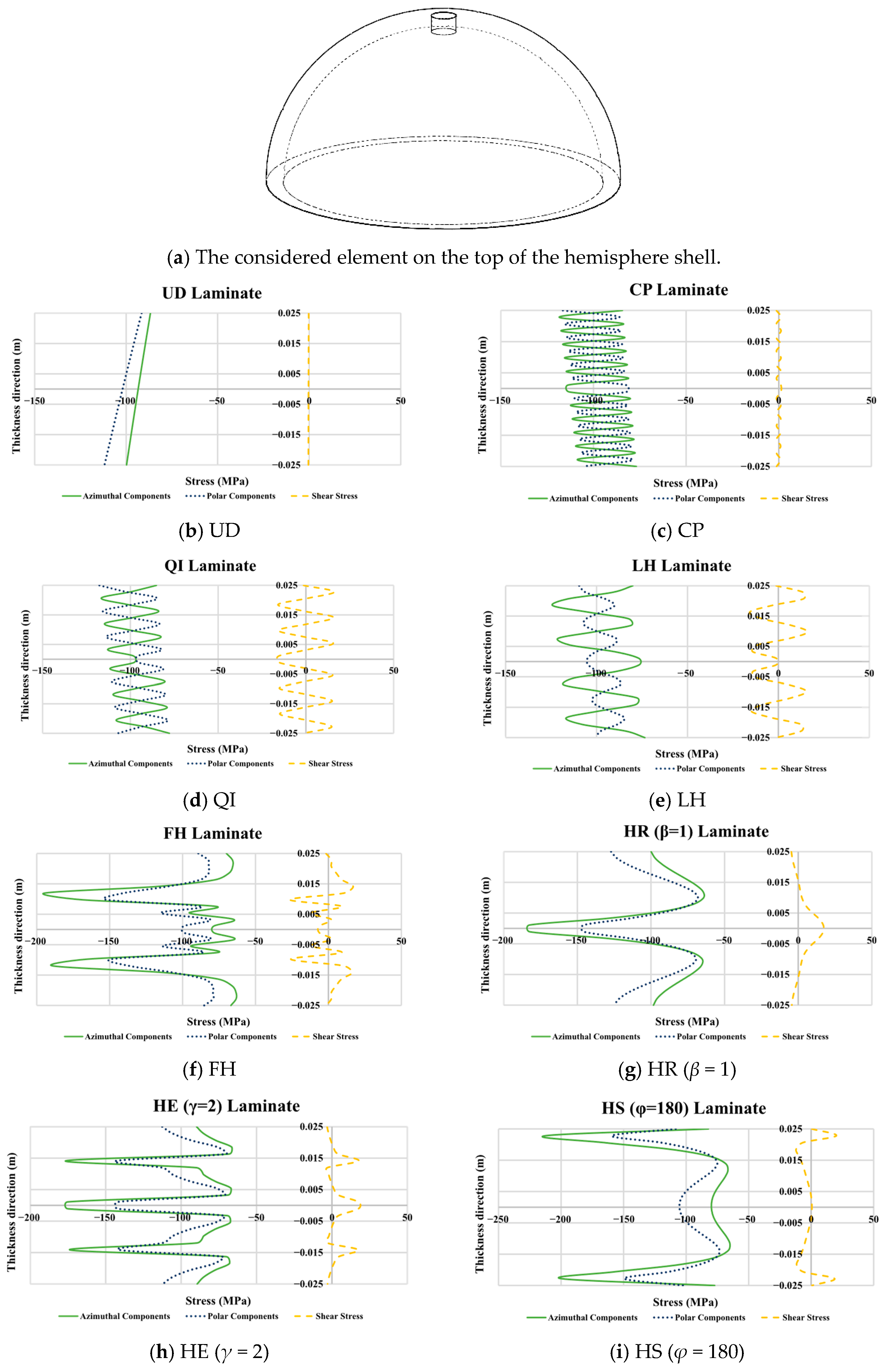
Figure 4 illustrates critical insights into interlaminar and through-thickness stress distributions in helicoidally laminated hemispherical shells exposed to evenly distributed external normal pressure, pointing to the influence of varying lamination designs. As depicted in Figure 4a, the topmost shell element subjected to external pressure remains in compression throughout, resulting in consistently negative principal stress components. The choice of lamination scheme significantly influences the magnitude of these stress components, with peak stress concentrations posing potential risks for material failure or interfacial delamination. Specifically, the HS (φ = 180°) configuration (Figure 4i) exhibits the highest compressive stresses in both azimuthal and polar directions, whereas the lowest azimuthal stresses are observed in the UD laminate (Figure 4b), and the minimal polar stresses occur in the LH pattern (Figure 4e). These results underscore the importance of tailored stacking sequences in mitigating critical stress build-up in curved composite laminates.
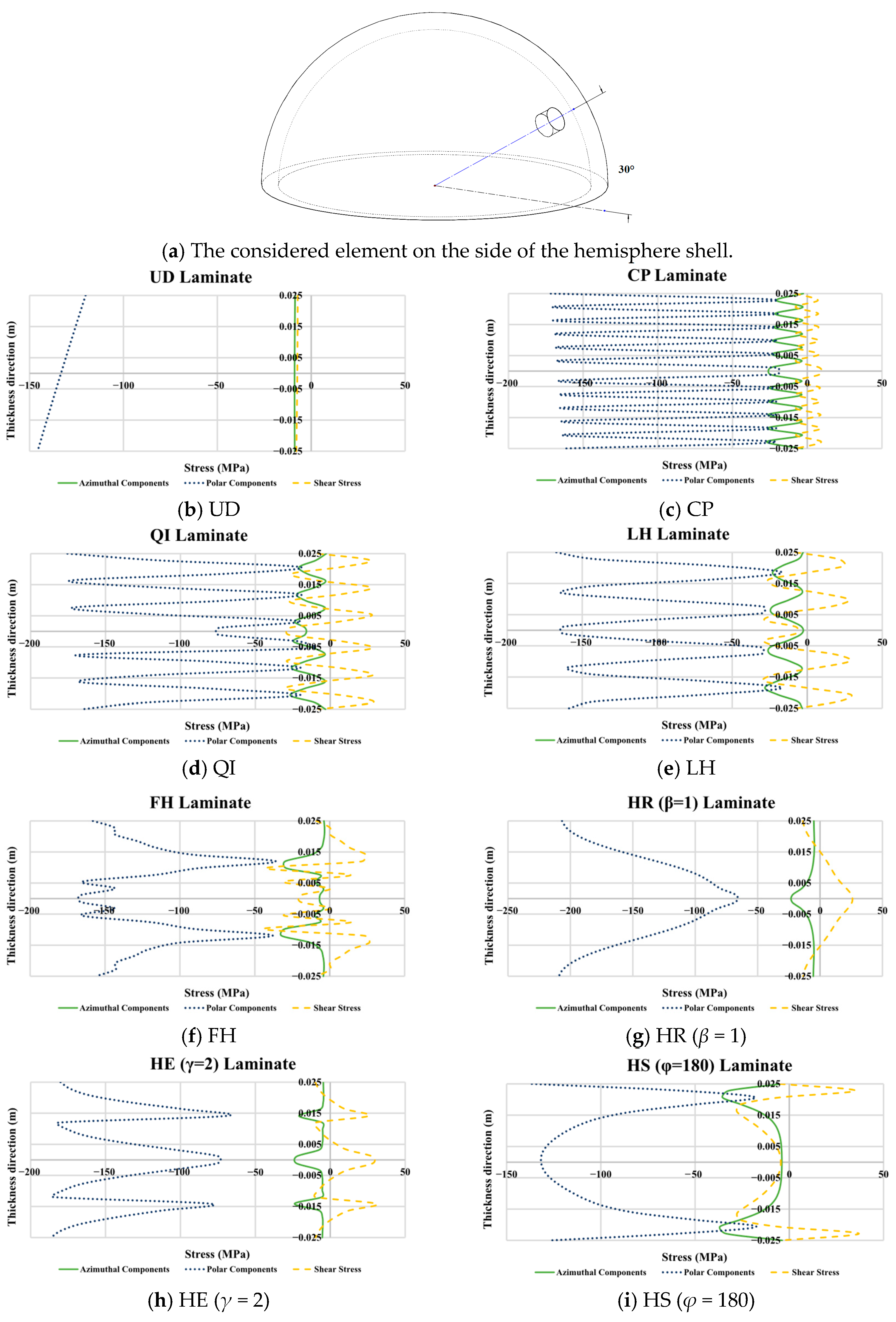
To further analyze the preceding numerical findings, Figure 5 illustrates the effect of the lamination scheme on the interlaminar and through-thickness stress distributions for a side element near the boundary of helicoidally laminated hemispherical shells under uniform static pressure. In contrast to the topmost element, where the azimuthal and polar stresses were comparable and the shear stress was minimal, the side element exhibits a markedly different behavior. Here, the polar stress component is dominant, while the azimuthal and shear stresses are of a similar, lower magnitude. Due to the external pressure, this side element is primarily in a state of compression, with nearly all principal stress components being negative. In contrast to the finding of Figure 4, the HR (β = 1) configuration yields the highest compressive polar stress in the side element, underscoring the critical influence of the element’s spatial location on the resultant stress field within the spherical shell.
As a subsequent set of novel results, Table 6 and Table 7 present the importance of lamination pattern, layer count (NoL), and shell thickness on the maximum static deflection under uniform pressure (Table 6) and the natural frequencies (Table 7) of bio-inspired helicoidal laminated composite hemispherical shells. In this study, the average radius is held constant at unity; hence, an increase in the thickness ratio corresponds to a reduction in relative thickness, rendering the shell more slender. As anticipated, enhancing the dimensional thickness ratio results in a significant rise in maximum deflection and an associated lowering of frequencies, consistent with the reduced structural stiffness of thinner configurations.
As evident from Table 6, for most lamination configurations—such as LH, HR (β = 1), HE = 2), and HS (φ = 180)—an increase in the number of layers ( N o L ) results in a reduction in static deflection, demonstrating an evident decline. Conversely, laminates such as UD, CP, and QI demonstrate minimal variation in deflection with changing N o L . Notably, the FH configuration shows an inverse behavior, where increasing N o L leads to a rise in deflection. For quantitative insight, averaging across thickness ratios and N o L increments (from 16 to 24 and 24 to 32 layers), the UD, CP, and QI laminates exhibit deflection changes of less than 0.003 mm, indicating negligible sensitivity to N o L . Conversely, LH, HS (φ = 180), HR (β = 1), and HE (γ = 2) display average reductions of 0.07, 0.27, 2.86, and 3.19 mm, respectively, reflecting stronger dependence on layer count. The FH configuration shows an average increase of 0.56 mm, further underscoring its distinct N o L sensitivity. Moreover, the effect of N o L is more pronounced in thinner shells (higher thickness ratios). For instance, doubling the number of layers from 16 to 32 results in an average deflection reduction of 0.60 mm for the thick shell with R ave / h = 10 , compared to 1.26 mm and 2.52 mm for R ave / h = 20 and 40, respectively.
The unexpected reduction in global stiffness (rise in deflection or reduction in natural frequencies) for the FH configuration with increasing layer count, as reported in Table 6, stems from its Fibonacci series-driven stacking sequence (e.g., 0°, 10°, 10°, 20°, 30°, 50°), which induces rapid, nonuniform angular increments in outer plies of laminates. These misaligned outer layers, critical to bending stiffness due to their distance from the mid-plane, reduce global rigidity under uniform pressure, while amplified extefabrinsion-bending coupling introduces further compliance. Notably, the number of layers is not the primary determinant of structural behavior; rather, the initial fiber orientations, geometric characteristics, type of analysis, and stacking sequence parameters predominantly govern the through-thickness stiffness distribution.
As the next numerical case, Table 7 presents the effects of lamination pattern, N o L , and thickness ratio on the free vibration characteristics of bio-inspired helicoidal laminated composite hemispherical shells. The results indicate that shell thickness has a relatively minor influence on natural frequencies. For instance, raising the geometric thickness ratio from 10 to 40—corresponding to a 75% decrease in initial thickness—induces only a marginal reduction in fundamental frequency. The most pronounced reduction across all configurations is observed in the 32-layer CP laminate, with a mere 1.083-fold decline, underscoring the limited sensitivity of vibrational response to thickness variation. Conversely, a higher layer count typically leads to higher natural frequencies, with the extent of enhancement varying significantly among lamination schemes. The HE (γ = 2) configuration exhibits the strongest dependence on N o L , showing a 1.5-fold rise in frequency when layers are increased from 16 to 32, averaged across thickness ratios. This highlights its superior tunability in dynamic performance through layer refinement. On the other hand, the UD, CP, QI, LH, and FH laminates show minimal sensitivity to NoL. Configurations such as HS (φ = 180) and HR (β = 1) demonstrate moderate positive dependency, with frequency enhancement factors of 1.1 and 1.4, respectively, confirming their intermediate responsiveness to layer count.
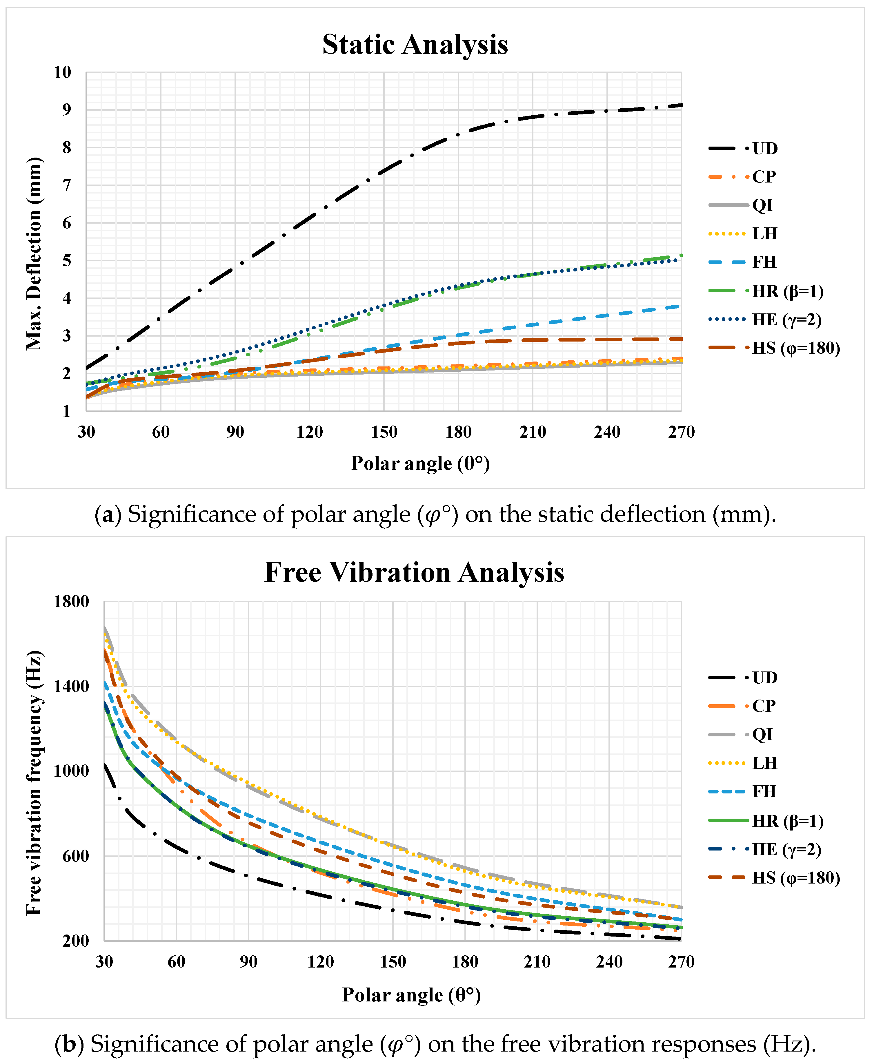
Figure 6 depicts the significance of polar angle as well as layup configuration on the (Figure 6a) static deflection and (Figure 6b) free vibration characteristics of helicoidally laminated spherical panels. Generally, increasing the polar angle results in a reduction in natural frequencies and an increase in deflections, consistent with the associated reduction in overall structural stiffness. Furthermore, the mechanical response exhibits diminishing sensitivity to further increases in polar angle beyond approximately 210°, as evidenced by the reduced slope of the curves and the onset of a plateauing trend in both deflection and frequency values. This suggests that beyond this threshold, the structural behavior approaches an asymptotic limit, where additional angular extension yields progressively smaller changes in performance, irrespective of lamination pattern.
In the static analysis (Figure 6a), the shell is exposed to a radial normal pressure of p = 10   M P a . It is evident that as the polar angle increases, the disparity in structural response among different lamination configurations becomes more pronounced. For instance, the variation in maximum deflection due to changes in lay-up pattern is only 0.79 mm for a shell with a polar angle of 30°, whereas it increases significantly to 6.83 mm for a shell with a polar angle of 270°. This indicates that the influence of lamination configuration intensifies with larger polar angles, rendering stacking sequence selection increasingly critical in more extensive spherical segments, while its effect remains relatively minor in shells with smaller angular spans. Furthermore, averaging across all polar angles, the configurations can be ranked in descending order of structural efficiency (i.e., from minimal to maximal deflection) as specified next: QI, LH, CP, HS (φ = 180°), FH, HR (β = 1), HE (γ = 2), and UD.
In the free vibration analysis (Figure 6b), it is evident that the influence of lamination configuration on the fundamental frequency decreases as the polar angle increases. Specifically, the variation in the first-mode natural frequencies among different lay-up patterns is 648 Hz for a polar angle of 30°, whereas it reduces to 148 Hz at 270°, indicating that the dynamic response becomes less sensitive to stacking sequence as the shell coverage expands. These findings indicate that lamination design exerts greater influence on vibrational behavior in spherical shells with reduced polar angles, while its significance diminishes as the polar angle increases. Moreover, the results demonstrate that free vibration frequencies exhibit greater sensitivity to changes in polar angle compared to static deflection. For instance, increasing the polar angle from 30° to 270° leads to a 5.03-fold decrease in the average first-mode frequency across all configurations, whereas the corresponding increase in maximum deflection is only 2.61-fold.
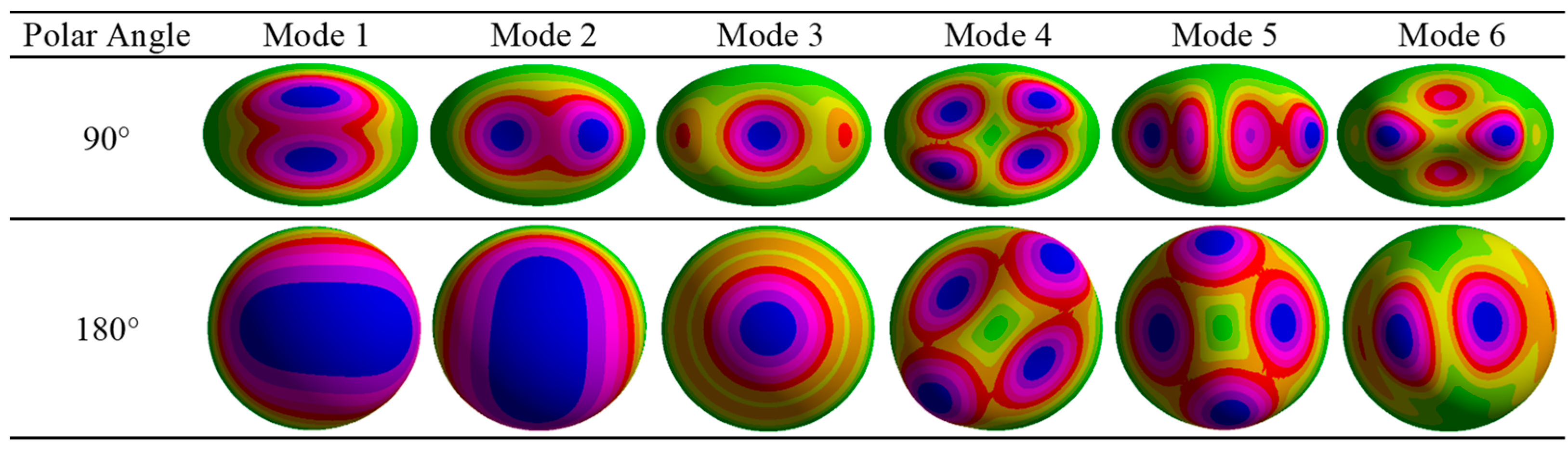
Furthermore, to facilitate a clearer understanding of the vibrational characteristics of the analyzed spherical shells, Figure 7 displays the free vibration mode shapes for QI composite partial spherical panels at varying polar angles. As illustrated, the polar angle significantly influences the spatial distribution and symmetry of the vibration modes, exerting a decisive influence on the propagation of vibrational waves and the amplitude of vibrational humps.
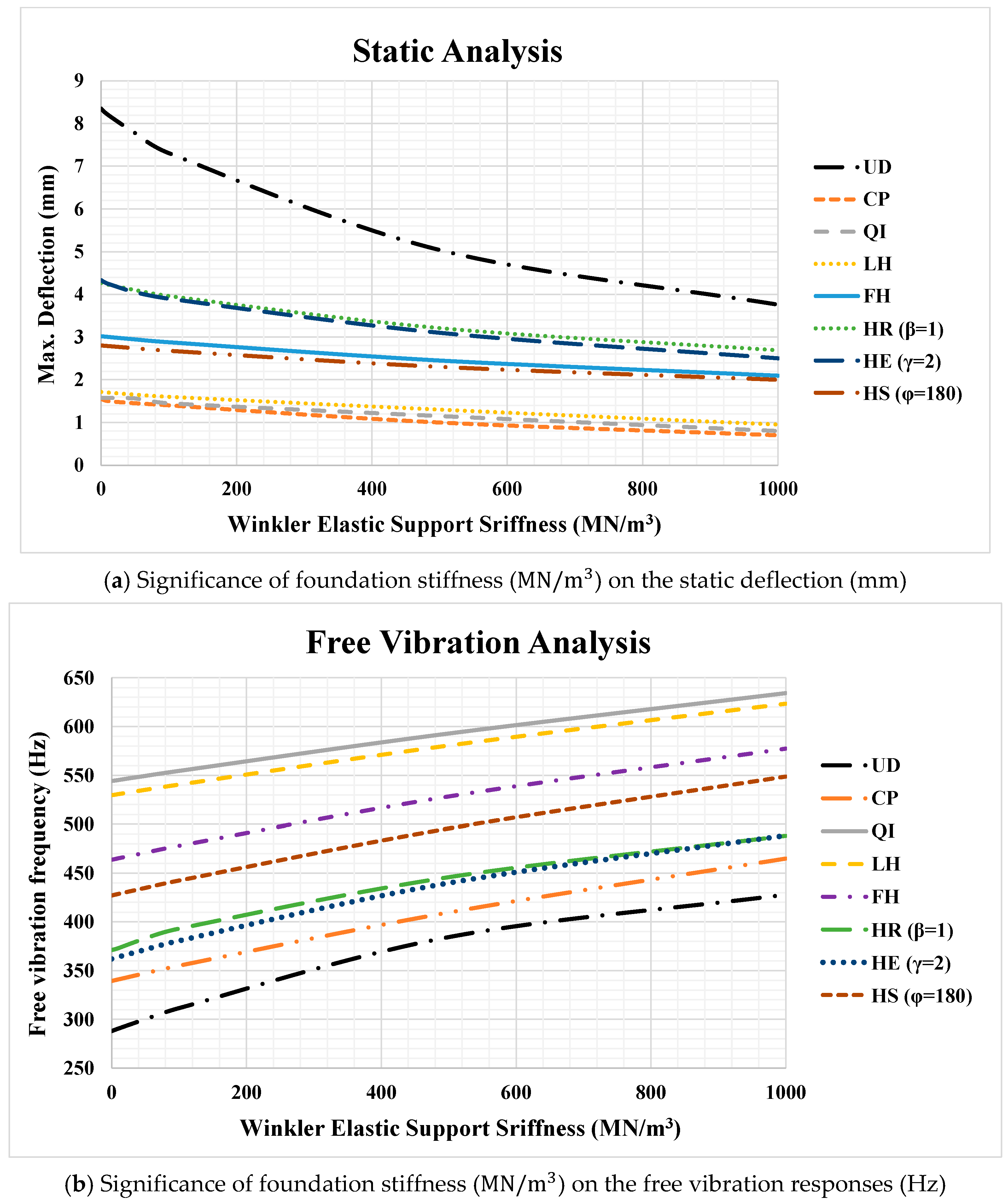
Figure 8 presents a graphical numerical example illustrating the impact of Winkler elastic foundation parameter and lamination configuration on (Figure 8a) static deflection and (Figure 8b) free vibration behavior of bio-inspired helicoidal laminated composite hemispherical shells. As anticipated, increasing the stiffness of the elastic support yields to a suppression in maximum static deformation and an elevation in natural frequencies. In the static case (Figure 8a), raising the stiffness from 0 to 1000 MN/m3 results in an average deflection reduction factor of 1.30 across all lamination schemes. The impact is most evident in UD pattern, which exhibits a reduction of 1.49. The sensitivity to elastic support follows the descending order: UD (1.49), CP (1.37), HE (γ = 2) (1.35), HR (β = 1) (1.32), HS (φ = 180) (1.28), FH (1.25), LH (1.18), and QI (1.17), indicating that lamination architecture significantly modulates structural response to foundation stiffness. In contrast, for the natural frequency analysis (Figure 8b), varying the stiffness from 0 to 1000 M N / m 3 results in an average enhancement of the first free vibration mode by a factor of 1.80 across all lamination configurations. The most pronounced effect is observed in the UD laminate, with a frequency increase of 2.22. The relative influence of the elastic support follows the descending order: UD (2.22), CP (2.21), QI (1.97), LH (1.81), HE (γ = 2) (1.73), HR (β = 1) (1.59), FH (1.44), and HS (φ = 180) (1.40). Notably, the effect of Winkler-type foundation stiffness is more significant on dynamic characteristics than on static deflection. On average, natural frequencies increase 1.80-fold compared to a 1.30-fold reduction in deflection over the same stiffness range, underscoring the greater sensitivity of vibrational response to elastic support augmentation.
Table 8 presents a detailed analysis of the effects of lamination configuration, polar angle, and boundary conditions on the static deflection and free vibration behavior of bio-inspired helicoidal laminated composite spherical shells. Evidently, a reduction in boundary constraint severity or an increase in polar angle results in decreased natural frequencies and elevated maximum deflections, indicating a direct influence of geometric and support conditions on structural stiffness and dynamic response.
Although partial spherical shells in practical applications typically incorporate edge fixations, their free vibration analysis under well-defined boundary conditions—such as clamped or simply supported constraints—yields fundamental modal characteristics essential for resonance avoidance and the prediction of dynamic responses. These intrinsic oscillatory modes, shaped by the prescribed restraints, elucidate how anisotropy-induced stiffness variations—arising from specific layup configurations—govern the structure’s dynamic behavior. Complementing this, in the free vibration results presented in Table 8, transitioning the edge constraints from fully clamped to simply supported for a hemispherical shell reduces the fundamental natural frequencies by an average multiplier of 1.18 over all ply configurations. For a spherical shell with a polar angle of 90°, the corresponding reduction factor is 1.12, indicating that shells with larger polar angles exhibit stronger dependence to boundary constraints. Furthermore, multiplying the polar angle by two, from 90° to 180° in clamped shells decreases the frequencies by an average factor of 1.77, whereas for simply supported shells, the reduction reaches a corresponding value of 1.87. This demonstrates a more dominant contribution of polar angle on dynamic response when the boundary conditions permit greater displacement freedom, underscoring the interplay between geometric extent and support flexibility in modulating structural stiffness.
In the static analysis results presented in Table 8, in contrast to the vibrational behavior, spherical shells at lower polar angles demonstrate stronger dependence on restraint conditions. Specifically, changing the edge constraints from fully clamped to simply supported for a hemispherical panel (polar angle = 180°) increases the maximum deflection by a mean multiplier of 1.31 over all stacking arrangements, whereas for a spherical shell with a polar angle of 90°, the increase reaches a factor of 1.43. This indicates that reduced geometric extent amplifies the structural response to support rigidity. Moreover, the influence of polar angle is more pronounced under stricter boundary constraints. For instance, reducing the polar angle from 180° to 90° in clamped shells decreases the maximum deflection by an average factor of 1.48, compared to decline factor of 1.35 in panels with simply supported edges. This demonstrates that geometric scaling has a more significant stiffening effect when boundary conditions are more restrictive.
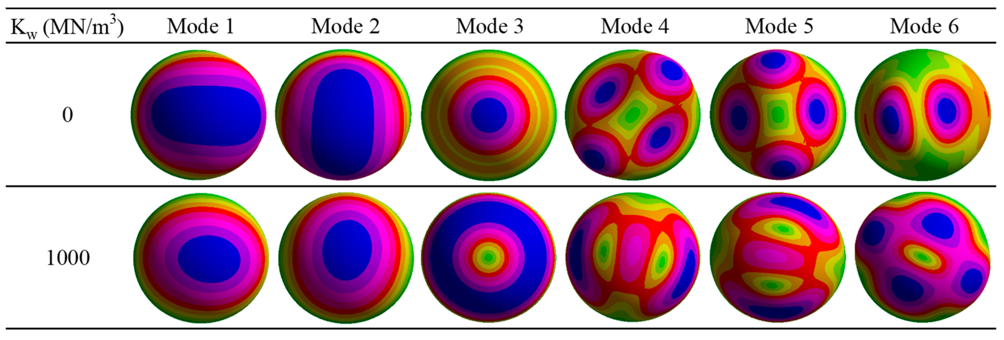
Finally, Figure 9 depicts the significance of the Winkler-support medium on the natural frequency mode shape results of bio-inspired composite hemispherical panels. As shown, the incorporation of Winkler foundation leads to more confined deformation modes, which feature higher wave numbers and an increase in the number of modal humps.
The anisotropic properties of helicoidal laminates synergistically couples with the curvature of partial spherical shells, giving rise to a multifaceted interaction not observed in flat laminates. In such curved geometries, vibrational modes exhibit intrinsic membrane–bending coupling, wherein the direction-dependent stiffness—resulting from progressive fiber rotation—determines each lamina’s role in the global structural response. The bio-inspired helicoidal stacking sequence induces a continuous variation in principal material directions through the thickness, promoting more effective stress distribution and mitigating localized stress concentrations. This architecture not only enhances resistance to curvature-induced stresses but also yields superior structural performance. Consequently, these features underpin the improved vibrational features and mechanical characteristics of helicoidal composites.

5. Conclusions

This study investigates the static and vibrational behavior of bio-inspired helicoidal laminated composite spherical shells resting on a Winkler-type elastic foundation. Based on three-dimensional elasticity theory and employing the finite element method (FEM), the governing equations of motion are formulated via Hamilton’s principle, enabling precise capture of thickness-stretching effects—offering a significant improvement over conventional equivalent single-layer theories. The analysis utilizes T300/5208 graphite/epoxy CFRP laminates and compares bio-inspired helicoidal stacking sequences with conventional layups. Parametric studies systematically evaluate the impact of ply arrangement, number of plies, polar angle, foundation stiffness, shell thickness, and edge constraints on natural frequencies, static deflections, and stress distributions. Key conclusions are as follows:
-
The quasi-isotropic laminate achieves the highest fundamental frequency, while the cross-ply configuration shows marginally superior static performance with minimum deflection. The unidirectional laminate exhibits the lowest performance in both static and dynamic behavior.
-
For static performance, the configurations are ranked in ascending order of effectiveness (i.e., from largest to smallest deflection) as follows: UD, HS (φ = 45°), HS (φ = 90°), HE (γ = 2), HR (β = 1), HE (γ = 3), FH, HS (φ = 180°), HE (γ = 2.5), HR (β = 3), HR (β = 2), LH, QI, and CP.
-
For natural frequency performance, the configurations are ranked in ascending order (i.e., from lowest to highest fundamental frequency): UD, CP, HS (φ = 45°), HE (γ = 2), HR (β = 1), HE (γ = 3), HS (φ = 90°), HE (γ = 2.5), HS (φ = 180°), FH, HR (β = 2), HR (β = 3), LH, and QI.
-
The HS (φ = 180°) configuration develops the highest compressive azimuthal and polar stresses for the topmost element on the shell; implying greater susceptibility to delamination or failure, whereas the UD laminate and LH pattern exhibit the lowest azimuthal and polar stresses, respectively.
-
The number of layers significantly affects both static and dynamic responses, with HE (γ = 2) exhibiting the greatest sensitivity. While most helicoidal configurations improve with higher NoL, FH shows anomalous behavior, and UD, CP, and QI remain largely insensitive. In contrast, shell thickness has negligible influence on vibration characteristics, underscoring NoL as the dominant design parameter.
-
Polar angle significantly impacts structural performance, with larger angles reducing natural frequencies and increasing deflections due to decreased stiffness, plateauing beyond 210°. Lamination effects intensify for static response at higher angles, while vibration response becomes less sensitive to stacking sequence as polar angle increases.
-
Increasing foundation stiffness from 0 to 1000 MN/m3 reduces static deflection by an average factor of 1.30 and elevates natural frequencies by 1.80×. The UD laminate exhibits the highest sensitivity to foundation stiffness in both static and dynamic responses.
-
Boundary conditions and polar angle interactively influence structural behavior: transitioning from clamped to simply supported reduces natural frequencies and increases deflections, with greater static sensitivity at smaller polar angles. Vibrational response is predominantly governed by polar angle, whereas static deflection is more sensitive to boundary conditions.

Author Contributions

Conceptualization, A.K., M.J.B., M.B. and K.A.; Methodology, A.K., M.J.B., M.B. and K.A.; Soft-ware, A.K. and M.J.B.; Validation, A.K., M.J.B., M.B. and K.A.; Formal analysis, A.K., M.J.B., M.B. and K.A.; Investigation, A.K., M.J.B. and M.B.; Data curation, A.K. and M.J.B.; Writing—original draft, A.K. and M.J.B.; Writing—review & editing, A.K., M.B. and K.A.; Supervision, K.A. All authors have read and agreed to the published version of the manuscript.

Funding

This research received no external funding.

Informed Consent Statement

Not applicable.

Data Availability Statement

Data will be made available on request.

Conflicts of Interest

The authors declare no conflicts of interest.

Appendix A. Fundamental Elasticity Formulations

The constitutive equations based on Hooke’s law, describing the linear elastic behavior of materials, can be formulated in a compact matrix representation as:
σ = D ε
The relationship among the stress and strain tensors and the stiffness coefficients D can be expressed in the following form [48]:
σ = { σ r σ ϕ σ θ σ r ϕ σ θ ϕ σ r θ } T
ε = { ε r ε ϕ ε θ γ r ϕ γ ϕ θ γ r θ } T
D = 1 ϑ 23 ϑ 32 E 2 E 3 ϑ 21 + ϑ 23 ϑ 31 E 2 E 3 ϑ 31 + ϑ 21 ϑ 32 E 2 E 3 0 0 0 ϑ 21 + ϑ 23 ϑ 31 E 2 E 3 1 ϑ 13 ϑ 31 E 1 E 3 ϑ 32 + ϑ 12 ϑ 31 E 1 E 3 0 0 0 ϑ 31 + ϑ 21 ϑ 32 E 2 E 3 ϑ 32 + ϑ 12 ϑ 31 E 1 E 3 1 ϑ 12 ϑ 21 E 1 E 2 0 0 0 0 0 0 G 23 0 0 0 0 0 0 G 13 0 0 0 0 0 0 G 12
Δ = 1 υ 12 υ 21 υ 23 υ 32 υ 13 υ 31 2 υ 21 υ 32 υ 13 E 1 E 2 E 3
υ i j E i = υ j i E j
where E i denotes the modulus of elasticity, and υ i j represents the Poisson’s ratio, both characterizing the material’s elastic properties in the context of varying properties arising from the radial lamination of the composite material.
Based on the principles of linear elasticity, the kinematic relationships between strain and displacement in a spherical coordinate system are formulated as follows [48]:
ε r = u r ,     ε ϕ = 1 r u + v ϕ ,     ε θ = 1 r sin ϕ w θ + sin ϕ u + cos ϕ v
γ θ ϕ = 1 2 r 1 sin ϕ v θ + w ϕ cot ϕ w ,     γ r ϕ = 1 2 1 r u ϕ + v r v r , γ r θ = 1 2 1 r sin ϕ u θ + w r w r
and can be represented in matrix notation as below:
ε = L U
In the above equation, L is a matrix of differential operators, and U denotes the displacement vector defined as follows:
U = { u v w } T
L = r 1 r 1 r 1 2 r ϕ 0 1 2 r sin ϕ θ 0 1 r ϕ 1 r cot ϕ 1 2 r 1 2 r 1 2 r sin ϕ θ 0 0 0 1 r sin ϕ θ 0 ϕ cot ϕ r 1 r T
Within the aforementioned equation, r i , θ i , ϕ i correspond to the nodal coordinates, while A i j identifies the submatrix derived from matrix V by excluding the i-th row and j-th column.

Appendix B. Finite Element Shape Function Definitions

The matrix components comprising Φ , the linear shape function matrix, are expressed as:
Φ i = 1 V Γ X
with V signifies the volume of each individual element, given by:
V = 1 ξ 1 η 1 ζ 1 ξ 1 η 1 ξ 1 ζ 1 η 1 ζ 1 ξ 1 η 1 ζ 1 1 ξ 2 η 2 ζ 2 ξ 2 η 2 ξ 2 ζ 2 η 2 ζ 2 ξ 2 η 2 ζ 2 1 ξ 3 η 3 ζ 3 ξ 3 η 3 ξ 3 ζ 3 η 3 ζ 3 ξ 3 η 3 ζ 3 1 ξ 4 η 4 ζ 4 ξ 4 η 4 ξ 4 ζ 4 η 4 ζ 4 ξ 4 η 4 ζ 4 1 ξ 5 η 5 ζ 5 ξ 5 η 5 ξ 5 ζ 5 η 5 ζ 5 ξ 5 η 5 ζ 5 1 ξ 6 η 6 ζ 6 ξ 6 η 6 ξ 6 ζ 6 η 6 ζ 6 ξ 6 η 6 ζ 6 1 ξ 7 η 7 ζ 7 ξ 7 η 7 ξ 7 ζ 7 η 7 ζ 7 ξ 7 η 7 ζ 7 1 ξ 8 η 8 ζ 8 ξ 8 η 8 ξ 8 ζ 8 η 8 ζ 8 ξ 8 η 8 ζ 8
The quantities Γ and X , originally introduced in Equation (A12), may be alternatively expressed as:
Γ i j = 1 i + j A i j
X = { 1 , ξ , η , ζ , ξ η , ξ ζ , η ζ , ξ η ζ } T
where
ξ = r cos θ sin ϕ , ° η = r sin θ sin ϕ , ° ζ = r cos ϕ
ξ i = r i cos θ i sin ϕ i , ° η i = r i sin θ i sin ϕ i , ° ζ i = r i cos ϕ i

References

  1. Iarriccio, G.; Zippo, A.; Pellicano, F. Asymmetric vibrations and chaos in spherical caps under uniform time-varying pressure fields. Nonlinear Dyn. 2022, 107, 313–329. [Google Scholar] [CrossRef]
  2. Shen, X.; Li, T.; Xu, L.; Kiarasi, F.; Babaei, M.; Asemi, K. Free vibration analysis of FG porous spherical cap reinforced by graphene platelet resting on Winkler foundation. Adv. Nano Res. 2024, 16, 11–26. [Google Scholar]
  3. Nam, V.H.; Tu, B.T.; Hung, V.T.; Van Doan, C.; Phuong, N.T. Nonlinear thermomechanical buckling and postbuckling analysis of sandwich FG-GPLRC complexly curved caps and circular plates with porous core. Acta Mech. 2025, 236, 421–438. [Google Scholar] [CrossRef]
  4. Haboussi, M.; Sankar, A.; Ganapathi, M. Nonlinear axisymmetric dynamic buckling of functionally graded graphene reinforced porous nanocomposite spherical caps. Mech. Adv. Mater. Struct. 2021, 28, 127–140. [Google Scholar] [CrossRef]
  5. Bagheri, H.; Kiani, Y.; Bagheri, N.; Eslami, M. Free vibrations of functionally graded material cylindrical shell closed with two spherical caps. Ships Offshore Struct. 2022, 17, 939–951. [Google Scholar] [CrossRef]
  6. Ubamanyu, U.K.; Baizhikova, Z.; Le, J.-L.; Ballarini, R.; Reis, P. A numerical study on the buckling of near-perfect spherical shells. J. Appl. Mech. 2025, 92, 051003. [Google Scholar] [CrossRef]
  7. Vu, H.N.; Pham, N.N.; Bui, T.T.; Vu, M.D.; Nguyen, T.P. A new semi-analytical approach for nonlinear electro-thermo-mechanical dynamic responses of FG-GPLRC shallow spherical caps and circular plates with porous core. J. Thermoplast. Compos. Mater. 2025, 38, 911–932. [Google Scholar] [CrossRef]
  8. Iarriccio, G.; Pellicano, F. Nonlinear dynamics and stability of shallow spherical caps under pressure loading. J. Comput. Nonlinear Dyn. 2021, 16, 021006. [Google Scholar] [CrossRef]
  9. Wang, D.; Zaheri, A.; Russell, B.; Espinosa, H.; Zavattieri, P. Fiber reorientation in hybrid helicoidal composites. J. Mech. Behav. Biomed. Mater. 2020, 110, 103914. [Google Scholar] [CrossRef]
  10. Le, V.T.; Ha, N.S.; Goo, N.S. Thermal protective properties of the allomyrina dichotoma beetle forewing for thermal protection systems. Heat Transf. Eng. 2019, 40, 1539–1549. [Google Scholar] [CrossRef]
  11. Gibson, L.J. The hierarchical structure and mechanics of plant materials. J. R. Soc. Interface 2012, 9, 2749–2766. [Google Scholar] [CrossRef]
  12. Sword, G.A.; Lecoq, M.; Simpson, S.J. Phase polyphenism and preventative locust management. J. Insect Physiol. 2010, 56, 949–957. [Google Scholar] [CrossRef] [PubMed]
  13. Lenau, T.; Barfoed, M. Colours and metallic sheen in beetle shells—A biomimetic search for material structuring principles causing light interference. Adv. Eng. Mater. 2008, 10, 299–314. [Google Scholar] [CrossRef]
  14. Sharma, A.; Shukla, N.K.; Belarbi, M.-O.; Abbas, M.; Garg, A.; Li, L.; Bhutto, J.; Bhatia, A. Bio-inspired nacre and helicoidal composites: From structure to mechanical applications. Thin-Walled Struct. 2023, 192, 111146. [Google Scholar] [CrossRef]
  15. Patek, S.a.; Caldwell, R. Extreme impact and cavitation forces of a biological hammer: Strike forces of the peacock mantis shrimp Odontodactylus scyllarus. J. Exp. Biol. 2005, 208, 3655–3664. [Google Scholar] [CrossRef]
  16. Patek, S.N.; Korff, W.; Caldwell, R.L. Deadly strike mechanism of a mantis shrimp. Nature 2004, 428, 819–820. [Google Scholar] [CrossRef] [PubMed]
  17. Suksangpanya, N.; Yaraghi, N.A.; Kisailus, D.; Zavattieri, P. Twisting cracks in Bouligand structures. J. Mech. Behav. Biomed. Mater. 2017, 76, 38–57. [Google Scholar] [CrossRef]
  18. Bayat, M.J.; Kalhori, A.; Asemi, K.; Babaei, M. Static and vibrational characteristics of bio-inspired helicoid laminated composite annular sector plates embedded on Winkler elastic foundation. Eng. Struct. 2025, 334, 120194. [Google Scholar] [CrossRef]
  19. Ginzburg, D.; Pinto, F.; Iervolino, O.; Meo, M. Damage tolerance of bio-inspired helicoidal composites under low velocity impact. Compos. Struct. 2017, 161, 187–203. [Google Scholar] [CrossRef]
  20. Li, Q.; Wu, L.; Hu, L.; Li, E.; Zou, T.; Liu, X. Parametric analysis on axial compression performance of bio-inspired porous lattice structures. Thin-Walled Struct. 2023, 182, 110223. [Google Scholar] [CrossRef]
  21. Gunasegeran, M.; Vasudevan, M.; Ramamoorthy, M.; Arumugam, A. Investigation of quasi-static indentation on sandwich structure with GFRP face sheets and PLA bio-inspired core: Numerical and experimental study. Thin-Walled Struct. 2023, 184, 110501. [Google Scholar] [CrossRef]
  22. Wang, J.; Liu, Y.; Wang, K.; Yao, S.; Peng, Y.; Rao, Y.; Ahzi, S. Progressive collapse behaviors and mechanisms of 3D printed thin-walled composite structures under multi-conditional loading. Thin-Walled Struct. 2022, 171, 108810. [Google Scholar] [CrossRef]
  23. Bayat, M.-J.; Kalhori, A.; Asemi, K.; Babaei, M. Plates, Beams and Shells Reinforced by CNTs or GPLs: A Review on Their Structural Behavior and Computational Methods. Comput. Model. Eng. Sci. 2025, 142, 1351–1458. [Google Scholar] [CrossRef]
  24. Melaibari, A.; Wagih, A.; Basha, M.; Kabeel, A.; Lubineau, G.; Eltaher, M. Bio-inspired composite laminate design with improved out-of-plane strength and ductility. Compos. Part A Appl. Sci. Manuf. 2021, 144, 106362. [Google Scholar] [CrossRef]
  25. Lu, T.; Shen, H.-S.; Wang, H.; Chen, X.; Feng, M. Optimization design and secondary buckling of bio-inspired helicoidal laminated plates under thermomechanical loads. Compos. Struct. 2023, 321, 117344. [Google Scholar] [CrossRef]
  26. Baakeel, F.K.; Eltaher, M.A.; Basha, M.A. Impact response of bio-inspired curved laminated composite plates: A numerical simulation. Adv. Aircr. Spacecr. Sci. 2025, 11, 331–361. [Google Scholar]
  27. Gowda, D.; Bhat, R.S. Bio-inspired helicoidal hemp/basalt/polyurethane rubber bio-composites: Experimental, numerical and analytical ballistic impact study with residual velocity prediction using artificial neural network. Ind. Crops Prod. 2024, 222, 119600. [Google Scholar] [CrossRef]
  28. Do, N.-T.; Pham, Q.-H. Dynamic analysis of bio-inspired helicoid laminated composite plates resting on Pasternak foundation excited by explosive loading. Def. Technol. 2023, 30, 126–140. [Google Scholar] [CrossRef]
  29. Garg, A. Finite element-based buckling analysis of bio-inspired laminated composite plates. J. Ceram. Compos. 2025, 1, 1–5. [Google Scholar]
  30. Saurabh, S.; Kiran, R.; Singh, D.; Vaish, R.; Chauhan, V. A comprehensive investigation on nonlinear vibration and bending characteristics of bio-inspired helicoidal laminated composite structures. Appl. Math. Mech. 2025, 46, 81–100. [Google Scholar] [CrossRef]
  31. Mohamed, S.A.; Mohamed, N.; Eltaher, M.A. Bending, buckling and linear vibration of bio-inspired composite plates. Ocean Eng. 2022, 259, 111851. [Google Scholar] [CrossRef]
  32. Garg, A.; Li, L. Influence of speed of soft body projectile on damage in bio-inspired helicoidal laminates using SPH-FEM model. Mech. Adv. Mater. Struct. 2024, 1–28. [Google Scholar] [CrossRef]
  33. Mohamed, N.; Eltaher, M.A.; Mohamed, S.A.; Abdelrahman, A.A. On static and dynamic stability of bio-inspired composite plates under variable axial load. Acta Mech. 2025, 236, 499–518. [Google Scholar] [CrossRef]
  34. Garg, A.; Shukla, N.K.; Avcar, M.; Belarbi, M.-O.; Zheng, W.; Raman, R.; Kiran, R.; Li, L. Free vibration analysis of annular and flat plates with sinusoidal corrugations using isogeometric analysis and machine learning-based stiffness modeling. Thin-Walled Struct. 2025, 215, 113492. [Google Scholar] [CrossRef]
  35. Garg, A.; Shukla, N.K.; Belarbi, M.-O.; Barnawi, A.B.; Raman, R.; Sharma, A.; Li, L. Free vibration analysis of bio-inspired helicoidal laminated composite square and annular plates having circular openings using isogeometric analysis. Structures 2024, 69, 107429. [Google Scholar] [CrossRef]
  36. Karamanli, A.; Vo, T.P.; Belarbi, M.-O.; Lee, S. On the bending, buckling and free vibration analysis of bio-inspired helicoidal laminated composite shear and normal deformable beams. Compos. Struct. 2025, 352, 118641. [Google Scholar] [CrossRef]
  37. Yang, F.; Xie, W.; Meng, S. Impact and blast performance enhancement in bio-inspired helicoidal structures: A numerical study. J. Mech. Phys. Solids 2020, 142, 104025. [Google Scholar] [CrossRef]
  38. Karamanli, A.; Pham, S.D.; Lee, S.; Vo, T.P. A Comprehensive Bending Analysis of Laminated Composite, Sandwich and Bio-Inspired Helicoidal Composite Curved Beams. SSRN (Social Science Research Network) 2024. [Google Scholar] [CrossRef]
  39. Almitani, K.H.; Mohamed, N.; Alazwari, M.A.; Mohamed, S.A.; Eltaher, M.A. Exact solution of nonlinear behaviors of imperfect bioinspired helicoidal composite beams resting on elastic foundations. Mathematics 2022, 10, 887. [Google Scholar] [CrossRef]
  40. Khotjanta, P.; Aimmanee, S. Optimal interply angle of bio-inspired composite curved panels with helicoidal fiber architecture. Compos. Struct. 2024, 343, 118269. [Google Scholar] [CrossRef]
  41. Garg, A.; Li, L.; Belarbi, M.-O.; Zheng, W.; Raman, R. Stochastic Free Vibration Behavior of Multi-Layered Helicoidal Laminated Composite Shells Under Thermal Conditions. J. Compos. Sci. 2025, 9, 106. [Google Scholar] [CrossRef]
  42. Thu, T.T.T.; Anh, T.N.; Thi, H.N. Transient response of doubly-curved bio-inspired composite shells resting on viscoelastic foundation subject to blast load using improved first-order shear theory and isogeometric approach. Def. Technol. 2024, 38, 171–193. [Google Scholar] [CrossRef]
  43. Garg, A.; Zheng, W.; Avcar, M.; Belarbi, M.-O.; Kiran, R.; Li, L.; Raman, R. Free vibration behaviour of curved Miura-folded bio-inspired helicoidal laminated composite cylindrical shells using HSDT assisted by machine learning-based IGA. Compos. Struct. 2025, 357, 118933. [Google Scholar] [CrossRef]
  44. Kalhori, A.; Bayat, M.J.; Asemi, K. Torsional and axial buckling analysis of bio-inspired helicoidal laminated composite cylindrical shells. Results Eng. 2025, 26, 104808. [Google Scholar] [CrossRef]
  45. Garg, A.; Li, L. Data-driven uncertainty quantification and sensitivity studies in free vibration behavior of bio-inspired helicoidal laminated composite cylindrical shells. Mech. Adv. Mater. Struct. 2024, 32, 749–764. [Google Scholar] [CrossRef]
  46. Ameri, E.; Aghdam, M.; Shakeri, M. Global optimization of laminated cylindrical panels based on fundamental natural frequency. Compos. Struct. 2012, 94, 2697–2705. [Google Scholar] [CrossRef]
  47. Sadd, M.H. Elasticity: Theory, Applications, and Numerics; Academic Press: Cambridge, MA, USA, 2009. [Google Scholar]
  48. Bayat, M.J.; Kalhori, A.; Babaei, M.; Asemi, K. Buckling Characteristics of Bio-Inspired Helicoidal Laminated Composite Spherical Shells Under External Normal and Torsional Loads Subjected to Elastic Support. Buildings 2025, 15, 3165. [Google Scholar] [CrossRef]
  49. Gautham, B.; Ganesan, N. Free vibration characteristics of isotropic and laminated orthotropic spherical caps. J. Sound Vib. 1997, 204, 17–40. [Google Scholar] [CrossRef]
Figure 1. Schematic representation of a bio-inspired laminated composite spherical panel, including (a) geometry and coordinate framework, (b) illustration of the bio-mimetic basis of helicoidal layering, (c) its engineering applications and (d) stress notation.
Buildings 16 00273 g001
Figure 2. Illustration of the investigated conventional and bio-inspired helicoid laminate architectures, depicting the stacking sequence and fiber orientation patterns for 24 layers ply stack.
Buildings 16 00273 g002
Figure 3. Angular variation in the in-plane elastic modules in polar form, illustrating the anisotropic behavior of different conventional and bio-inspired lamination sequences ( N o L = 24 ).
Buildings 16 00273 g003
Figure 4. Significance of lamination pattern on the stress distribution (MPa) through the shell thickness (m) of laminated hemisphere shells exposed to pressure of p = 10   M P a ( R a v e h = 20 , N o L = 24 , φ = 180 ° (hemispherical panel), full-clamped); (a) The considered element on the top of the shell, (b) UD, (c) CP, (d) QI, (e) LH, (f) FH, (g) HR (β = 1), (h) HE (γ = 2), (i) HS (φ = 180).
Buildings 16 00273 g004
Figure 5. Significance of lamination pattern on the stress distribution (MPa) through the shell thickness (m) of laminated hemisphere shells exposed to pressure of p = 10   M P a ( R a v e h = 20 , N o L = 24 , φ = 180 ° (hemispherical panel), full-clamped); (a) The considered element on the side of the shell, (b) UD, (c) CP, (d) QI, (e) LH, (f) FH, (g) HR (β = 1), (h) HE (γ = 2), (i) HS (φ = 180).
Buildings 16 00273 g005
Figure 6. Influence of lamination pattern and polar angle ( φ ° ) on the (a) static deflection (mm) and (b) first mode of fundamental frequencies (Hz) of helicoid composite spherical shells ( R a v e h = 20 , N o L = 24 , Clamped).
Buildings 16 00273 g006
Figure 7. Significance of polar angle ( φ ° ) on the free vibration mode shapes of QI composite spherical panels ( R a v e h = 20 , N o L = 24 , Clamped, QI arrangement).
Buildings 16 00273 g007
Figure 8. Influence of lamination pattern and Winkler support stiffness ( M N / m 3 ) on the (a) static deflection (mm) and (b) free vibration results (Hz) of bio-inspired laminated hemispherical panels ( R a v e h = 20 , N o L = 24 , φ = 180 ° (hemispherical panel), full-clamped).
Buildings 16 00273 g008
Figure 9. Influence of Winkler elastic support on the free vibration mode shapes of Quasi-isotropic composite hemispherical panels ( R a v e h = 20 , N o L = 24 , φ = 180 ° , full-clamped, QI arrangement).
Buildings 16 00273 g009
Table 1. The layer ordering of the assorted helicoidal layup arrangements according to N o L [28,31,44].
Number of Layers (NoL)
ConfigurationAbbreviationStacking Sequence
[ ( a 1 / a 2 / / a n / / a N o L 2 ) ]
162432
UnidirectionalUD[(0) N o L ][(0) 16][(0) 24][(0)32]
Cross plyCP[(0/90) (   N o L 4 )] s[(0/90) 4] s[(0/90) 6] s[(0/90) 8] s
Quasi isotropicQI[(0/45/90/−45) (   N o L 8 )] s[(0/45/90/−45) 2] s[(0/45/90/−45) 3] s[(0/45/90/−45) 4] s
Linear HelicoidalLH a 1 = 0 , a 2 = ( 360 N o L 2 1 ) ; a n , n 3 = a n 1 + a 2 [(0/51.43/…/360)] s[(0/32.72/…/360)] s[(0/24/…/360)] s
Fibonacci HelicoidalFH a 1 = 0 , a 2 = 10 ; a n , n 3 = a n 1 + a n 2 [(0/10/10/20/…/130)] s[(0/10/10/20/…/890)] s[(0/10/10/20/…/6100)] s
Helicoidal RecursiveHR (β = 1) a n = a n 1 + β n 1 [(0/1/3/6/10/15/21/28)] s[(0/1/3/6/10/15/21/28/36/45/55/66)] s[(0/1/3/6/10/15/21/28/36/45/
55/66/78/91/105/120)] s
Helicoidal ExponentialHE (γ = 2) a n = γ n [(2/4/8/16) 2] s[(2/4/8/16/32/64) 2] s[(2/4/8/16/32/64/128/256) 2] s
Helicoidal SemicircularHS (φ = 180) a n = φ 2 ( χ ( n 1 ) φ ) 2 ( χ = 26 );
[(0/93.2/126.6/148.3/163.2/
172.9/178.4/180)] s
( χ = 16 );
[(0/74.2/102.4/122.4/137.6/149.7/159.2/
166.7/172.3/176.4/178.9/180)] s
( χ = 12 );
[(0/64.6/89.8/108.0/122.4/134.2/
144.0/152.3/159.2/165.0/169.7/
173.5/176.4/178.4/179.6/180)] s
Table 2. Material properties of the T300/5208 graphite/epoxy lamina under consideration [46].
Property NameValue
Density (kg/m3)1540
E11 (GPa)132.5
E22 = E33 (GPa)10.8
ν12 = ν130.24
ν230.49
G12 = G13 (GPa)5.7
G23 (GPa)3.4
Table 3. Validation of computed natural frequencies (Hz) of copper partial spherical panel with different polar angles compared with the results reported by Shen et al. [2] ( a = 0.225   m , b = 0.25   m , E = 130   G P a , ρ = 8960   k g / m 3 , υ = 0.34 ).
Polar AngleReferenceMode 1Mode 2Mode 3Mode 4Mode 5Mode 6
180°Shen et al. [2]
(ANSYS)
1412.71472.92147.72387.22488.12720.3
Shen et al. [2]
(3D Elasticity)
1401.31458.62107.72370.12450.82690.8
Present1448.11507.82141.52367.52423.52679.5
90°Shen et al. [2]
(ANSYS)
2710.02921.32971.93634.13652.33691.5
Shen et al. [2]
(3D Elasticity)
2701.02901.82913.83600.83620.93618.6
Present2730.42880.12939.23667.93628.73712.4
Table 4. Validation of computed dimensionless lowest frequencies ( Ω = ω R ρ / E T ) for a clamped hemispherical laminated composite shell cap across varying layup configurations and thickness ratios against the results reported by Gautham et al. [49].
Lay-Up Sequence
00/90[0/90/0/90] s
Rave/hGautham et al. [49]
FSDT & FEM
PresentGautham et al. [49]
FSDT & FEM
PresentGautham et al. [49]
FSDT & FEM
Present
1000.8840.8651.1571.1481.1421.132
500.9320.9471.1831.1861.1811.214
201.1301.1481.2371.2101.2601.245
Table 5. Impact of lay-up pattern and corresponding configuration parameters on the fundamental frequencies and static bending of helicoidally laminated hemisphere shells ( R a v e h = 20 , N o L = 24 , φ = 180 ° (hemispherical panel), full-clamped).
Free Vibration Frequency (Hz)Static Deflection (mm)
PatternParameterMode 1Mode 2Mode 3Mode 4Mode 5Mode 6 Max .   Deflection   ( P = 10 M P a )
UD 287.95373.91409.39462.95504.10526.578.35
CP 339.43452.37535.78585.84609.26665.911.54
QI 544.08544.49736.19850.32850.96866.001.58
LH 529.66552.05736.41832.09855.13857.051.71
FH 463.69519.20614.56704.62724.33757.723.02
HR β = 1 371.06455.71487.38575.09604.47629.414.27
β = 2 476.61552.04678.46765.49778.43832.041.96
β = 3 482.93548.30681.62770.60779.30824.382.21
HE γ = 2 362.13458.81490.50583.75607.07638.284.33
γ = 2.5 424.15529.29600.75683.73734.55768.142.48
γ = 3 376.56489.60531.63624.76680.54702.623.07
HS φ = 45 , χ = 4 361.06401.69449.73541.36561.49581.965.12
φ = 90 , χ = 8 404.79457.76541.24623.69670.79689.634.34
φ = 180 , χ = 16 427.03525.88598.90682.67710.35756.552.80
Table 6. Impact of lamination pattern, layer count ( N o L ) and thickness ratio ( R a v e h ) on the static deflection (mm) of helicoidally laminated hemisphere shells exposed to a static pressure of p = 10 Mpa ( φ = 180 ° (hemisphere), Clamped).
R a v e / h
N o L Pattern102040
16UD4.0498.34716.566
CP0.8301.5402.930
QI0.8491.5722.965
LH0.9551.7893.413
FH1.3202.5054.860
HR ( β = 1 )3.5107.11814.101
HE ( γ = 2 )3.8337.83315.571
HS ( φ = 180 , χ = 26 )1.6583.1996.260
24UD4.0498.34716.566
CP0.8331.5422.934
QI0.8521.5782.972
LH0.9181.7153.256
FH1.5753.0215.893
HR ( β = 1 )2.1584.2698.401
HE ( γ = 2 )2.1934.3308.516
HS ( φ = 180 , χ = 16 )1.4662.8055.462
32UD4.0498.34716.566
CP0.8341.5432.936
QI0.8531.5792.974
LH0.9011.6783.183
FH1.7913.4546.771
HR ( β = 1 )1.1392.1774.257
HE ( γ = 2 )1.2312.3344.519
HS ( φ = 180 , χ = 12 )1.4352.7385.331
Table 7. Impact of lamination pattern, layer count ( N o L ) and thickness ratio ( R a v e h ) on the fundamental frequencies of helicoidally laminated hemisphere shells ( φ = 180 ° (hemisphere), Clamped).
R a v e h
102040
N o L PatternMode 1Mode 2Mode 3Mode 4Mode 5Mode 6Mode 1Mode 2Mode 3Mode 4Mode 5Mode 6Mode 1Mode 2Mode 3Mode 4Mode 5Mode 6
16UD295.73381.52442.93486.24581.01608.90287.95373.91409.39462.95504.10526.57284.89367.33396.78442.80446.30482.64
CP353.11462.17560.13629.41683.86750.50338.93451.74535.37585.03608.29665.38326.70442.06527.08557.13574.30607.57
QI541.88543.04742.62857.32859.87898.29543.32543.96735.21849.89850.91863.53541.58541.96728.69851.12851.27851.49
LH521.75551.17739.66831.08868.91893.06521.87554.20732.99821.60846.99858.88519.79553.71728.75821.36829.73853.71
FH462.79532.99654.30752.55790.41845.81462.32536.59641.57732.91736.50784.69460.91536.48637.55704.35721.15748.77
HR ( β = 1 )336.43402.78462.06551.03604.83640.96331.24401.66429.46519.50520.91553.97329.68399.15416.08463.35487.87506.44
HE ( γ = 2 )313.09391.60450.66514.26592.10625.17306.26386.85417.00487.46511.58536.90303.59382.02403.86452.82462.41492.33
HS ( φ = 180 , χ = 26 )407.40509.06592.90699.94741.04804.87399.65503.51560.54647.15679.57721.86393.84496.21544.73595.75629.77658.59
24UD295.73381.52442.93486.24581.01608.90287.95373.91409.39462.95504.10526.57284.89367.33396.78442.80446.30482.64
CP353.96462.86561.27630.58685.93751.12339.43452.37535.78585.84609.26665.91327.04442.45527.28557.57574.58607.97
QI543.10543.85744.37858.78860.54904.39544.08544.49736.19850.32850.96866.00542.07542.31729.38851.27851.52852.19
LH529.31549.60743.14841.06866.41898.18529.66552.05736.41832.09855.13857.05527.56551.15731.51832.41839.03855.59
FH463.45514.44631.12747.08783.89814.61463.69519.20614.56704.62724.33757.72463.39520.10609.19666.93702.78708.24
HR ( β = 1 )375.20461.08519.93646.22662.38716.28371.06455.71487.38575.09604.47629.41369.15449.01470.49520.91552.37568.37
HE ( γ = 2 )368.25467.12526.03639.38679.02724.64362.13458.81490.50583.75607.07638.28358.79449.30471.93526.38556.85574.11
HS ( φ = 180 , χ = 16 )433.91528.24625.25730.58767.60831.04427.03525.88598.90682.67710.35756.55421.38520.80587.17639.11669.97700.95
32UD295.73381.52442.93486.24581.01608.90287.95373.91409.39462.95504.10526.57284.89367.33396.78442.80446.30482.64
CP354.35463.18561.81631.12686.87751.32339.78452.51536.14586.19609.44666.38327.20442.64527.38557.79574.72608.16
QI543.63544.18745.09859.41860.78907.10544.43544.74736.70850.54851.11867.11542.29542.47729.69851.33851.53852.61
LH533.07548.47744.21845.90864.90900.27533.54550.62737.44837.07855.85858.87531.43549.43732.03837.65843.14855.22
FH449.07502.11606.13727.09756.05792.27449.02506.43587.09672.62700.10731.02448.90507.24580.44632.04670.97676.16
HR ( β = 1 )453.56541.86655.32775.69777.02836.07451.05543.31640.63719.90757.72795.88447.92541.40634.65690.87717.29751.48
HE ( γ = 2 )465.98539.02669.21772.35807.58852.01464.14541.80653.31739.87756.92808.07461.70541.14647.44706.94732.64765.02
HS ( φ = 180 , χ = 12 )442.04532.20634.04737.62774.29834.81435.73530.81610.22693.20717.21764.13430.35526.62599.88652.58682.01711.68
Table 8. Impact of lamination pattern, polar angle ( φ ) and edge condition on the fundamental frequencies and static bending of helicoidally laminated spherical shells ( R a v e h = 20 , N o L = 24 ).
φ
90° 180°
BCAnalysisPatternUDCPQILHFHHR ( β = 1 )HE ( γ = 2 )HS ( φ = 180 )UDCPQILHFHHR ( β = 1 )HE ( γ = 2 )HS ( φ = 180 )
Clamped
supported
Free vibration
Frequency (Hz)
Mode 1505.39662.28926.57943.56792.53648.15642.54758.98287.95339.43544.08529.66463.69371.06362.13427.03
Mode 2541.58792.54971.15952.47815.49676.88684.54813.98373.91452.37544.49552.05519.20455.71458.81525.88
Mode 3683.32804.531003.60981.96933.38812.95817.44930.08409.39535.78736.19736.41614.56487.38490.50598.90
Mode 4691.95891.461083.301079.60980.96876.27879.57977.62462.95585.84850.32832.09704.62575.09583.75682.67
Mode 5704.18966.711112.701087.10989.37894.15896.94992.01504.10609.26850.96855.13724.33604.47607.07710.35
Mode 6793.52995.661123.601129.401049.00956.02958.021045.70526.57665.91866.00857.05757.72629.41638.28756.55
Max. Static
Deflection (mm)
under P = 10   M P a
4.821.601.621.592.042.412.562.088.351.541.581.713.024.274.332.80
Simply
supported
Free vibration
frequency (Hz)
Mode 1469.30556.14842.34824.18718.32593.23584.80682.03252.89278.75452.14443.70393.63319.36314.09368.06
Mode 2495.57698.94875.86860.56733.92626.70630.08735.97326.70392.91453.58460.35427.32378.69391.31453.02
Mode 3612.14701.66879.20899.49816.22707.87717.50812.57387.39519.96644.50649.38559.88452.96461.18566.98
Mode 4631.23778.00924.33913.13880.47773.33777.13876.40454.33551.34818.14809.62667.00526.34536.66647.58
Mode 5648.67851.97948.75948.74891.23800.32800.47887.68470.77583.08821.54816.86709.96571.50579.47685.71
Mode 6732.12895.781007.90995.63917.46837.07842.53906.55498.86628.91834.12831.50726.26601.04612.88732.51
Max. Static
Deflection (mm)
under P = 10   M P a
5.553.153.233.072.763.363.132.5710.471.972.142.284.106.105.793.40
Disclaimer/Publisher’s Note: The statements, opinions and data contained in all publications are solely those of the individual author(s) and contributor(s) and not of MDPI and/or the editor(s). MDPI and/or the editor(s) disclaim responsibility for any injury to people or property resulting from any ideas, methods, instructions or products referred to in the content.