Article

Orientation-Resolved Thermal and Hygric Performance of Camel-Hair-Reinforced Rammed-Earth Walls Versus Hollow Concrete Block: A Six-Month, Two-Climate Comparative Field Study

1
Department of Interior Design, College of Arts and Design, Princess Nourah bint Abdulrahman University, P.O. Box 84428, Riyadh 11671, Saudi Arabia
2
Department of Architecture Engineering, Faculty of Engineering, Horus University in Egypt, Dumyat 34517, Egypt
3
Department of Architecture Engineering, College of Engineering and Information Technology, Buraydah Colleges, Buraydah 51418, Saudi Arabia
*
Author to whom correspondence should be addressed.
Buildings 2026, 16(18), 3738; https://doi.org/10.3390/buildings16183738 (registering DOI)
Submission received: 31 July 2026 / Revised: 11 September 2026 / Accepted: 11 September 2026 / Published: 20 September 2026
(This article belongs to the Section Building Materials, and Repair & Renovation)

Abstract

Field evidence for earthen and natural-fibre walls in hot climates remains scarce. This study reports a six-month field comparison of two wall constructions, instrumented on both faces at Riyadh (hot-arid) and Taif (milder highland), Saudi Arabia. Twenty-four sensors logged temperature and humidity every 15 min on three orientations of two open test cells with identical 300 mm walls: one of rammed earth reinforced with camel hair, the other of hollow concrete block. Twelve outer/inner wall pairs were analysed over 1708 wall-days. The earth wall damped the daily temperature swing more than the concrete block in every orientation at both sites: mean decrement factor 0.42 versus 0.58 at Taif and 0.47 versus 0.64 at Riyadh, holding on 86–99% of matched days. Mean inner-face amplitude fell from 12.5 to 7.0 °C at Riyadh. Time lag reached 3.2 h at Riyadh against 1.3 h for concrete block, but the materials were indistinguishable at Taif. Once construction moisture had dissipated, the earth wall damped the daily absolute-humidity swing by 57–58% against 11–48% for concrete block. Because the cells are open and unconditioned, these descriptors are comparative indices rather than transferable wall properties, and no cooling-load saving is inferred.

1. Introduction

The buildings and construction sector consumes about 32% of global final energy and is responsible for roughly 34% of energy-related carbon dioxide emissions, a share that has risen by some 5% since 2015 rather than falling towards the trajectory implied by the Paris Agreement [1]. In hot regions the dominant component of that demand is space cooling, and the dominant driver of cooling demand in low-rise construction is the opaque envelope. Vertical walls present the largest continuous area of that envelope, and because each orientation receives a different sequence of solar radiation through the day, the thermal behaviour of a wall is inseparable from the direction it faces. Any credible assessment of a wall system in a hot climate therefore has to resolve orientation, not merely report a single average.
The distinction matters because the two ways of reducing envelope heat gain are physically different. A lightweight, highly resistive wall reduces the magnitude of the transmitted heat flux but delivers what remains almost in phase with the outdoor peak. A heavyweight wall may transmit a comparable total quantity of heat over twenty-four hours, but it absorbs energy into its own mass during the day, releases it after sunset, and therefore presents a smaller and later load to whatever cooling system serves the space. In a climate with a diurnal swing of fifteen to twenty degrees, the second behaviour can matter more to peak plant sizing and to peak-hour electricity demand than the first does to annual energy. Yet compliance frameworks in most jurisdictions are still framed primarily around steady transmittance, which systematically undervalues mass. Any material claim about a heavyweight envelope therefore needs to be supported by dynamic descriptors—amplitude attenuation and phase shift—measured under real forcing rather than inferred from a U-value.
Saudi Arabia is a useful setting in which to test such a claim. Its climate spans a wide range within one country, from the hot-arid interior to the comparatively temperate western highlands, so one experimental design can be repeated under genuinely different forcing. Its housing stock is dominated by hollow-block construction, much of it built with limited or no envelope insulation, which supplies both an unambiguous control and the practical motivation: envelope performance is now an explicit focus of national code development and of compliance studies for Saudi dwellings [2]. The conventional remedy is petrochemical insulation applied to block construction, which works thermally but imports embodied carbon, depends on industrial supply chains, and sets aside a long regional tradition of building with earth and animal products. Camel husbandry is meanwhile widespread across the peninsula, and the hair shed or shorn annually is treated overwhelmingly as a waste stream rather than as a material resource.
Interest in bio-based envelope materials has grown accordingly. Recent reviews document a broad family of plant- and animal-derived insulations whose thermal conductivities approach those of mineral wool while carrying far lower embodied carbon, and whose pronounced hygroscopicity gives them a second, moisture-regulating function that synthetic foams do not possess [3]. Among animal fibres, sheep wool is the best characterised: reported conductivities cluster around 0.032–0.054 W m−1 K−1 and the fibre buffers water vapour strongly enough to stabilise the humidity of adjacent air [4,5,6,7]. Camel hair shares the keratin chemistry and the two-coat morphology that give wool these properties, and in the arid belt of the Arabian Peninsula it is an abundant, under-used by-product rather than an imported commodity.
Rammed earth offers the structural counterpart. Built from locally excavated soil compacted in formwork, it is a high-mass, low-carbon envelope whose value lies less in resisting heat than in storing and delaying it, and whose behaviour is strongly coupled to moisture [8,9,10]. Combining the two—an earth matrix reinforced with camel hair—should in principle place thermal mass, fibrous resistance and hygroscopic buffering in a single wall whose bulk is site-won soil. Whether it does so under real solar loading, and by how much relative to the hollow concrete block it would have to displace, is an empirical question that has not been answered.
There is also a reason to expect the combination to outperform either constituent alone. Earth walls fail thermally in two characteristic ways: they crack on drying, which opens convective paths through the section, and their conductivity rises with moisture content, eroding their advantage when the wall is wet. Fibre reinforcement addresses the first by distributing shrinkage strain across many small cracks rather than a few large ones [11,12], and a hygroscopic fibre may moderate the second. Camel hair is therefore a candidate solution to two known weaknesses of the matrix it is placed in, which is a stronger hypothesis than “natural fibre lowers conductivity”.

1.1. Related Work

Envelope-driven cooling load depends on both the steady transmittance of a wall and its dynamic response to a periodic outdoor forcing, and where the daily swing is large, the second is often the more consequential. Code frameworks have historically emphasised steady transmittance, and compliance analyses for Saudi dwellings show substantial predicted savings from meeting envelope U-value targets [2], but they do not by themselves reward the phase behaviour a heavyweight envelope provides. The case for exploiting that behaviour has been made repeatedly for locally available materials: insulation produced from date palm waste, for example, improves both thermal comfort and energy performance in arid-climate buildings while valorising an agricultural residue [13].
Bio-based insulation reviews consistently report that the advantage of plant- and animal-derived products lies in embodied rather than operational terms: their conductivities are typically a little higher than mineral wool or expanded polystyrene, so a slightly thicker layer is needed for the same resistance, but their production energy and associated emissions are far lower [3].
Field measurement of rammed earth consistently shows strong damping and long delays. Long-term in situ monitoring reported time lags above seven hours and decrement factors below 0.15 for a 0.37 m wall, with an uninsulated 0.29 m wall giving 6.5–9.0 h and 0.19–0.26 [8]. Monitoring of rammed-earth dwellings in northwest Sichuan found indoor daily variation of about 3.6 °C against a summer outdoor maximum of 42.6 °C [10]. Modified rammed-earth formulations combine thermal buffering with moisture regulation [9], whereas chemical stabilisation alters that hygrothermal response in ways that are not always favourable [14]. Stabilised formulations incorporating construction and demolition waste with calcium oxide reach conductivities near 0.88 W m−1 K−1 [15], an order of magnitude above fibrous insulation. Earth walls earn their performance through capacity rather than resistance. Table 1 collects these field-measured values, which set the expectation against which the present results are read in Section 3.
Sheep wool is the reference animal fibre for building applications. Composites bound with latex or acrylic-polyurethane resin achieve conductivities of 0.032–0.044 W m−1 K−1 [4]; wool-hemp products have been evaluated for durability and mechanical stability [5]; and wool bio-composites have been characterised thermally, acoustically and mechanically for low-carbon construction [6,7]. In wool combined with sugarcane bagasse, camel wool gave the best combined sound absorption, insulation and fire behaviour of the fibres compared [17].
Critically for the present work, animal fibre has also been used inside earthen matrices rather than as a separate insulation layer. Wool fibres increase the fracture energy and energy absorption of earthen material [11], and low-grade sheep wool is a viable reinforcement for earthen building components [18]. Clay bricks reinforced with Timahdite sheep wool achieved conductivity reductions of about 27% for white clay and 17% for red clay, with flexural strength rising and compressive strength falling moderately [19]. The mechanism—fibres bridging shrinkage cracks while introducing low-conductivity, air-filled paths—is what a camel-hair-reinforced earth wall would be expected to exploit. Two qualifications recur and are carried into this study as expectations from the literature rather than as measured properties of the present wall: fibre additions that lower conductivity generally lower compressive strength [16,19,20], and the durability of animal fibre in a moist matrix is the least well-evidenced dimension of the field [3]. Neither was tested here.
Camel hair is a two-coat fibre: coarse guard hairs of roughly 40–60 µm provide mechanical structure, while a fine undercoat of roughly 12–20 µm forms a dense, tortuous network that traps still air, many undercoat fibres being medullated so that internal voids further reduce heat transmission. Discriminant analysis confirms that camel hair and merino wool are distinguishable on fibre metrics while occupying a similar functional space [21]. The insulative comparison is not new—comparative testing against wool was published in 1938 [22]—and the double coat has more recently been used as a biomimetic template for a porous elastic fibre for dual-mode thermal regulation [23].
Direct building-oriented characterisation remains sparse. Preliminary work on camel hair as an architectural material in Saudi Arabia reports a thermal conductivity of approximately 0.038 ± 0.002 W m−1 K−1 by heat-flow meter and a composite panel R-value within 5–10% of sheep-wool batt insulation [24]. Those are laboratory values on prepared specimens. No published study places camel hair in a wall and measures what the wall then does over a season, which is the gap this paper addresses.
The wider fibre-earth literature indicates what fibre addition does and does not achieve. A state-of-the-art review of fibre-reinforced rammed earth concludes that fibre principally improves tensile and post-crack behaviour rather than compressive strength [12], and cyclic testing of rammed-earth walls reinforced with Arundo donax demonstrates the seismic relevance of that ductility [25]. Optimisation of compressed earth blocks shows the familiar trade-off in which additions that lower conductivity also lower strength [16], and bio-based additions such as sawdust improve hygroscopic and thermal performance at some mechanical cost [20].
Chemical stabilisation is the most common alternative to fibre reinforcement and carries a hygrothermal penalty that is easy to overlook: cement or lime raises strength and water resistance but alters the sorption behaviour of the matrix and reduces its moisture-regulating capacity [14,15]. The design space is therefore three-dimensional—strength, thermal performance and hygric performance—and the unstabilised, fibre-reinforced wall studied here occupies a different point in it from a cement-stabilised one. That is a deliberate choice: the assembly tested in this paper contains no chemical stabiliser at all.
The two standard descriptors of dynamic wall behaviour are the decrement factor, the ratio of inner to outer temperature amplitude, and the time lag, the delay between the outer and inner peaks. Both were formalised for wall evaluation using heat flux as well as temperature [26], and the values obtained depend significantly on the boundary conditions imposed [27], with dimensionless formulations proposed to make results comparable across cases [28]. This matters here, because the present cells are unconditioned and partially open, so their inner boundary condition is neither a laboratory hot box nor a conditioned room.
A second point concerns the quantity the descriptors are computed. They may be defined on surface temperature or on heat flux, and the two are not interchangeable: heat-flux-based descriptors respond to the thermal admittance of the internal surface as well as to transmission through the section [26,28]. The present study reports temperature-based descriptors because surface temperature is what the instrumentation measures directly and no heat-flux plates were deployed. This makes the values comparable with the temperature-based in situ literature [8,9] but not with heat-flux formulations.
The capacity of a material to moderate indoor humidity is quantified by the moisture buffer value, defined through the NORDTEST round-robin [29] and linked to whole-building simulation [30]. Keratin fibres are strongly hygroscopic and earthen matrices are hygroscopic too, which is why hygrothermal studies of rammed earth report coupled heat and moisture behaviour rather than thermal behaviour alone [9,14]. Because relative humidity is itself a function of temperature, comparisons across a wall must be made in absolute humidity or vapour pressure.
The framework was, however, developed for conditioned interiors under prescribed step changes in relative humidity, and it does not transfer cleanly to an open field cell whose boundary condition is the weather. What can be measured there is the attenuation of the daily absolute-humidity cycle across the wall, which reflects sorption capacity, vapour permeability and surface transfer jointly and is not convertible to a laboratory moisture buffer value. The present study therefore reports swing attenuation and mean vapour content, and treats them as evidence of buffering behaviour rather than as a material property.
Outdoor test cells occupy the middle ground between laboratory hot-box measurement and monitoring of occupied buildings. A comprehensive review classifies them into absolute and comparative types and notes that comparative testing—identical cells differing only in the component under study, exposed simultaneously to the same weather—is the more robust approach, because both cells share the same forcing and the same instrumentation errors [31]. Non-air-conditioned outdoor test cells have been used successfully to compare envelope systems, with measurements interpreted alongside simulation [32]. The design adopted here is explicitly comparative in that sense: two cells, same site, same weather, differing in wall material, with every wall instrumented on both faces so that each orientation yields an independent paired comparison.
The principal cost of the comparative approach is that absolute performance figures do not transfer to occupied buildings. A small, unconditioned, partially open cell has a different internal boundary condition, a different surface-to-volume ratio and a different ventilation regime from a room, so its interior surface temperatures are not indoor temperatures and its decrement factors are not the same as those the wall would exhibit in service [31]. What transfer is the ranking and the magnitude of the difference between two assemblies exposed side by side, which is precisely what a comparative design is for. This distinction is maintained throughout the present paper: material comparisons are made between cells, and absolute values are reported for transparency but not used to project energy savings.

1.2. Research Gap

Three gaps motivate this work. First, camel hair has been characterised almost exclusively at the fibre or textile scale—its physical properties relative to merino wool [21], its insulative value in comparative textile testing [22], and the biomimetic potential of its double-coat structure [23]—with only preliminary work on architectural application [24]. Its behaviour in a full-scale wall exposed to solar and weather loading over a season, measured outdoors against a conventional control, is unreported.
Second, the natural-fibre earth literature is dominated by laboratory specimens. Studies of wool in earthen materials establish improvements in fracture energy [11], mechanical performance [18] and thermal conductivity of clay bricks [19], and reviews of fibre-reinforced rammed earth catalogue the available stabilisation routes [12], but comparatively few studies place a fibre-earth wall outdoors beside a conventional control and monitor both for months. Fewer still resolve the comparison by orientation, and we are aware of none that does so simultaneously in two contrasting climates within one experimental design.
Third, the hygric behaviour of a new earth wall is confounded by the construction water it must shed. Rammed earth is placed moist and dries over months; measurements taken during that transient describe the drying process rather than the material’s steady behaviour, yet field studies rarely separate the two explicitly. Establishing when an earth wall reaches hygric steady state is a prerequisite for interpreting any moisture result from it.

1.3. Objectives and Research Questions

This paper addresses all three gaps by instrumenting both faces of every wall of two test cells—one of rammed earth reinforced with camel hair, one hollow concrete block—at a hot-arid and a milder highland site, and monitoring them at 15-min resolution for six months spanning late winter to peak summer. Three questions are posed:
(i)
By how much does a camel-hair-reinforced rammed-earth wall dampen the daily temperature swing relative to hollow concrete block, and does any advantage hold across orientation and across climate?
(ii)
How do thermal time lag and the across-wall temperature difference differ by material, orientation and site, and how do they differ between day and night?
(iii)
Once construction moisture has dissipated, does the assembly buffer the daily moisture swing, and does that buffering differ between an arid and a more humid climate?
The contribution claimed here is empirical rather than conceptual. Neither rammed earth nor animal fibre is new to building research, and this study proposes no new material or method. What it provides is a paired, orientation-resolved, two-climate field dataset for a wall system that has not previously been monitored outdoors at full scale, an explicit separation of construction drying from steady hygric behaviour, evidence that the drying transient suppresses the thermal advantage while it lasts, and a candid account of the artefacts that open test-cell geometry introduces into conventional dynamic thermal metrics. The design is deliberately narrow: two wall types, one thickness, one control, and no laboratory characterisation of either constituent. Section 4.7 sets out what that narrowness costs.

2. Materials and Methods

2.1. Experimental Sites and Climate

Two open-air experimental sites were established. Riyadh, in the arid interior of the Arabian Peninsula, represents the hot-arid desert regime. Taif, in the western highlands, represents a comparatively milder and more humid regime in which elevation moderates temperature relative to the surrounding lowlands. The two sites bracket the dominant warm-climate conditions of the country. Both installations are rooftop sites within residential districts, so both cells at a given site experience the same sky, the same wind exposure and the same weather. Climate descriptors used in this paper are confirmed against the measured boundary data reported in Section 3.1 rather than assumed a priori.

2.2. Test-Cell Design and Wall Assemblies

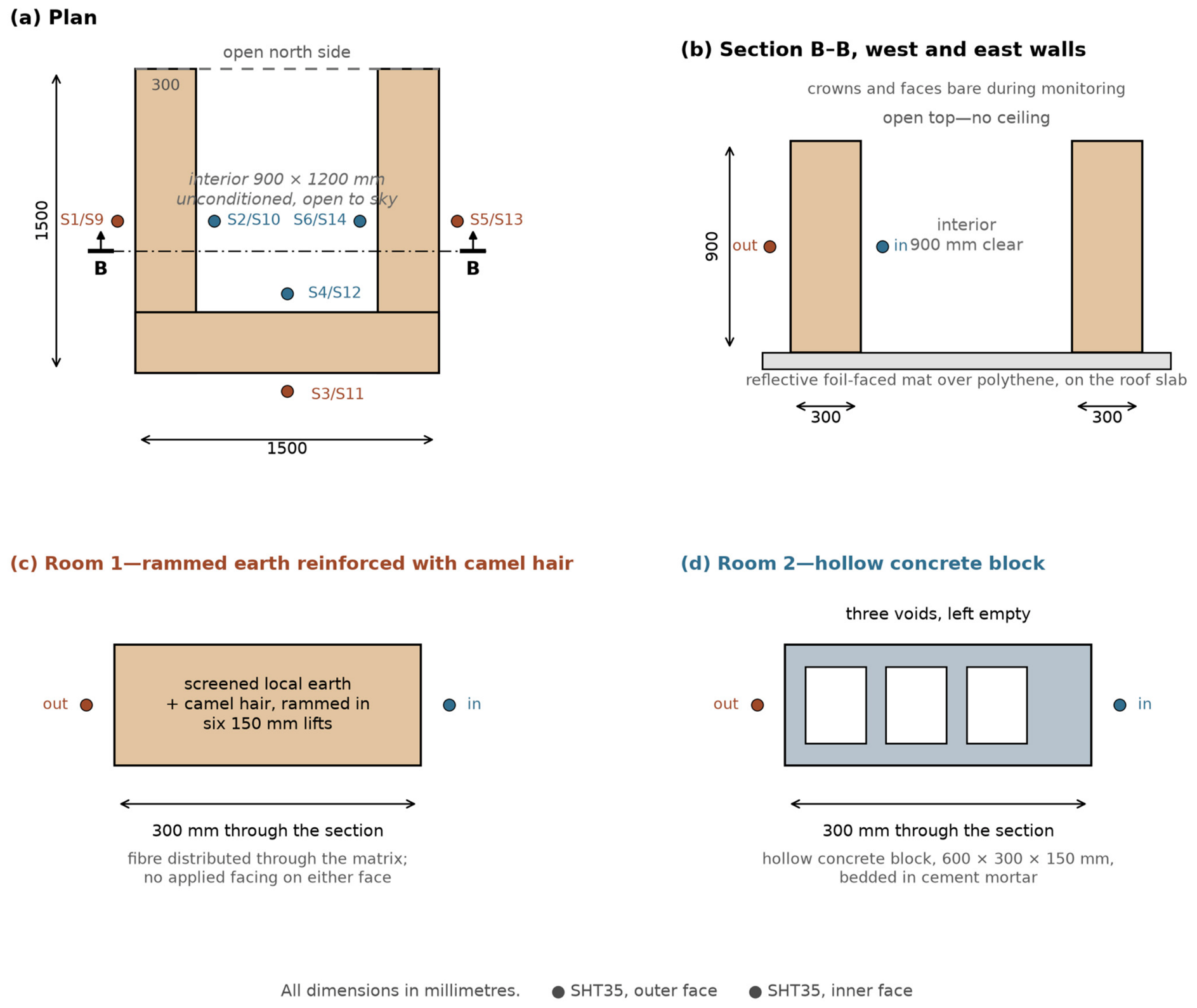
At each site, geometrically identical test cells were constructed. Each cell comprises three walls—west, south and east—with the north side left open and no ceiling over the interior volume. Every cell measures 1500 × 1500 mm on plan and 900 mm high to the top of the walls, over outer dimensions. All walls are 300 mm thick in every cell and at both sites, so the two materials are compared at identical thickness. The resulting interior is a clear void of 900 mm between the west and east walls by 1200 mm from the south wall to the open north side, 900 mm high and open to the sky. Figure 1a,b gives the dimensioned plan and section. The interior is unconditioned and freely ventilated. This configuration was chosen deliberately: it exposes all three orientations of each wall type to identical weather simultaneously, and it removes any dependence of the result on an assumed interior set-point. It also has substantial consequences for how the absolute values of the dynamic metrics must be read, which are set out in Section 4.1 and Section 4.7.
The reason the cells were left open should be stated plainly, because it governs how every number in this paper must be read, and because the justification offered in our first revision was not adequate. We argued there that an open cell removes the need to assume an interior set-point. That is true, but it does not distinguish this design from the obvious alternative: a closed cell left unconditioned requires no set-point either, and would additionally have given the inner faces a genuine interior boundary. The argument therefore did not support the design that was built, and we withdraw it.
The actual reason was experimental and financial. The crown of each cell was itself an experimental surface: the top of the rammed-earth cell carried a camel-hair layer under test as roof insulation, instrumented above and below, while the concrete-block cell carried a bare crown-surface sensor as its control. Roofing the cells would have removed that surface. Extending the camel-hair layer to span the full 1.5 × 1.5 m opening, rather than the 1.17 m2 wall crown, was beyond the fibre budget, because the hair was purchased and imported rather than collected locally. The open configuration is therefore a consequence of running two experiments on one set of cells under a fixed budget, not a considered thermal design choice, and Section 4.7 records it as a limitation. Instrumenting three orientations of each cell was a separate and deliberate choice, and gives three independent paired comparisons per site instead of one.
The design is comparative in the sense established in Section 1.1: the two cells at a site are built to the same plan, on the same roof and within metres of each other. They differ in the wall material under test and, as set out below, in the treatment of the wall crown. They therefore share the same solar geometry, the same sky temperature, the same wind exposure and the same weather sequence, and their sensors are of the same type and were commissioned at the same time. Any systematic error common to both cells cancels in the paired comparison that forms the basis of the material claim, while errors specific to one sensor or one facade do not, which is why the orientation-level anomalies identified in Section 3.6 are reported individually rather than averaged away.
The price of that choice is real and is not confined to the limitations. Because the interior is open to the sky along its north side and above, the nominal inner face is washed by outdoor air and exchanges longwave radiation with the sky in parallel with conduction through the wall, and in places receives direct sun. It is therefore not an indoor surface and its temperature is not an indoor temperature. Both consequences follow immediately: the inner-face amplitude is larger than conduction alone would produce, which raises the decrement factor, and its peak is pulled towards the ambient peak, which shortens the apparent time lag. The absolute values reported here are accordingly treated throughout as comparative indices measured under a common and deliberately severe boundary condition, not as transferable properties of a 300 mm wall, and no cooling-load or energy saving is inferred from them. Repeating the measurement in enclosed, conditioned cells is the single most valuable next step, and with hindsight we would have built such cells alongside the open ones rather than instead of them.
This paper concerns two cells at each site. In Room 1 the walls were built by compacting a moist mixture of locally excavated, screened earth and cleaned camel hair in formwork. The fibre is distributed through the matrix; neither wall face carries an applied insulation layer. In Room 2 the walls are lightweight hollow concrete blocks laid in cement mortar with the voids left empty. The units are 600 × 300 × 150 mm with three voids and a nominal shell and web thickness of 50 mm, laid on their bed so that the 300 mm dimension forms the wall thickness and the voids run vertically through each 150 mm course; the 900 mm wall is therefore six courses. The voids were left empty and are interrupted at every bed joint, so they form discrete air cells within the section rather than a continuous cavity. Bedding and perpend joints were formed in a conventional cement–sand mortar; the mix proportion was not recorded, and no strength or density testing was carried out on either the units or the mortar. Figure 1 shows the cell plan, the two wall build-ups and the sensor positions. Every wall carries a matched pair of sensors, one on the exposed outer surface and one on the interior surface, so that each of the twelve walls in the study yields an independent outer/inner comparison.

2.3. Radiation Boundary Conditions at the Wall Faces

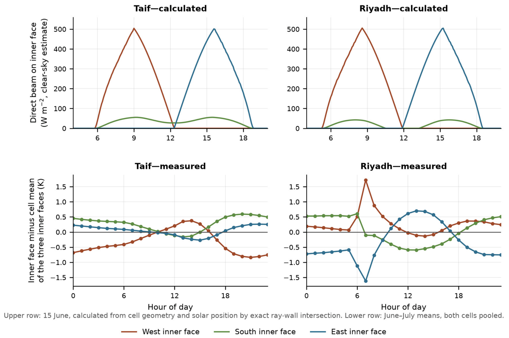
Because the cells are open above and along their north side, the inner faces are not shaded surfaces and their radiation boundary condition has to be stated rather than assumed. We therefore computed, from the cell geometry and solar position at each site, when and to what extent direct beam radiation reaches each inner face. The calculation is geometric: sunlit area is weighted by the cosine of the incidence angle, because a vertical surface under a near-zenith sun is geometrically exposed yet absorbs almost nothing, and irradiance is estimated with a clear-sky direct-normal model; shadowing of each face by the surrounding walls is solved analytically, as the intersection of each ray with the wall volumes, rather than by sampling along the ray. No pyranometer was deployed, so the irradiances below are calculated estimates and are labelled as such throughout.
The result is that two of the three inner faces carry a substantial and systematic direct-beam load. The inner face of the west wall, which looks east, is irradiated for 5.3 to 6.5 h each day with a mid-morning peak, and the inner face of the east wall, which looks west, mirrors it with a mid-afternoon peak. At both sites the peak beam projection factor on these faces reaches 0.4 to 0.7 between February and July, corresponding to an estimated 280 to 505 W m−2 on the surface and a daily total of 0.84 to 1.87 kWh m−2. The inner face of the south wall faces north and is never meaningfully irradiated: its daily total stays below 0.5 kWh m−2 at Taif and below 0.3 kWh m−2 at Riyadh, and reaches even that only in June and July, when the noon sun passes close to the zenith and strikes the face at grazing incidence. Whether the measured record carries the signature this predicts is a question for the results, and it is tested in Section 3.1.
Longwave exchange with the sky is the other half of the inner boundary condition, and it can be stated in the same way. Computing the sky view factor of each inner face from the same geometry by cosine-weighted ray casting gives 0.28 for the south inner face and 0.30 for the west and east inner faces. The reference values bracket what this means: a vertical wall standing unobstructed in the open has a sky view factor of 0.50, and the internal surface of a closed room has 0.00. The inner faces of these cells therefore retain roughly three-fifths of the sky coupling of a fully exposed outdoor surface, and radiate to the night sky accordingly. Together with the direct-beam load above, this is the quantitative content of the statement, made throughout this paper, that the nominal inner face is not an indoor surface. Air movement in the void was not measured, so the convective boundary condition is not quantified; the interior is open along its north side and above and is therefore freely ventilated rather than still. Outer faces are fully exposed, with a sky view factor of 0.50 apart from any local obstruction, and their sensors are unshielded and surface-mounted, so they report a surface microclimate rather than air temperature.
Two consequences follow, and they are carried into the interpretation rather than left here. First, the decrement factors of the west and east pairs are inflated relative to the south pair, because part of their inner-face amplitude is imposed directly by the sun rather than conducted through the wall. The south pair is accordingly the least contaminated of the three, and it is the south walls that return the lowest decrement factors at both sites, as reported in Section 3.6. Second, because the effect is fixed by geometry and orientation and is shared by the two cells at a site, it largely cancels in the paired, day-matched difference on which the material claim rests. It does not cancel in the absolute values, which is one more reason those are reported here as comparative indices only.

2.4. Material Preparation and Construction Sequence

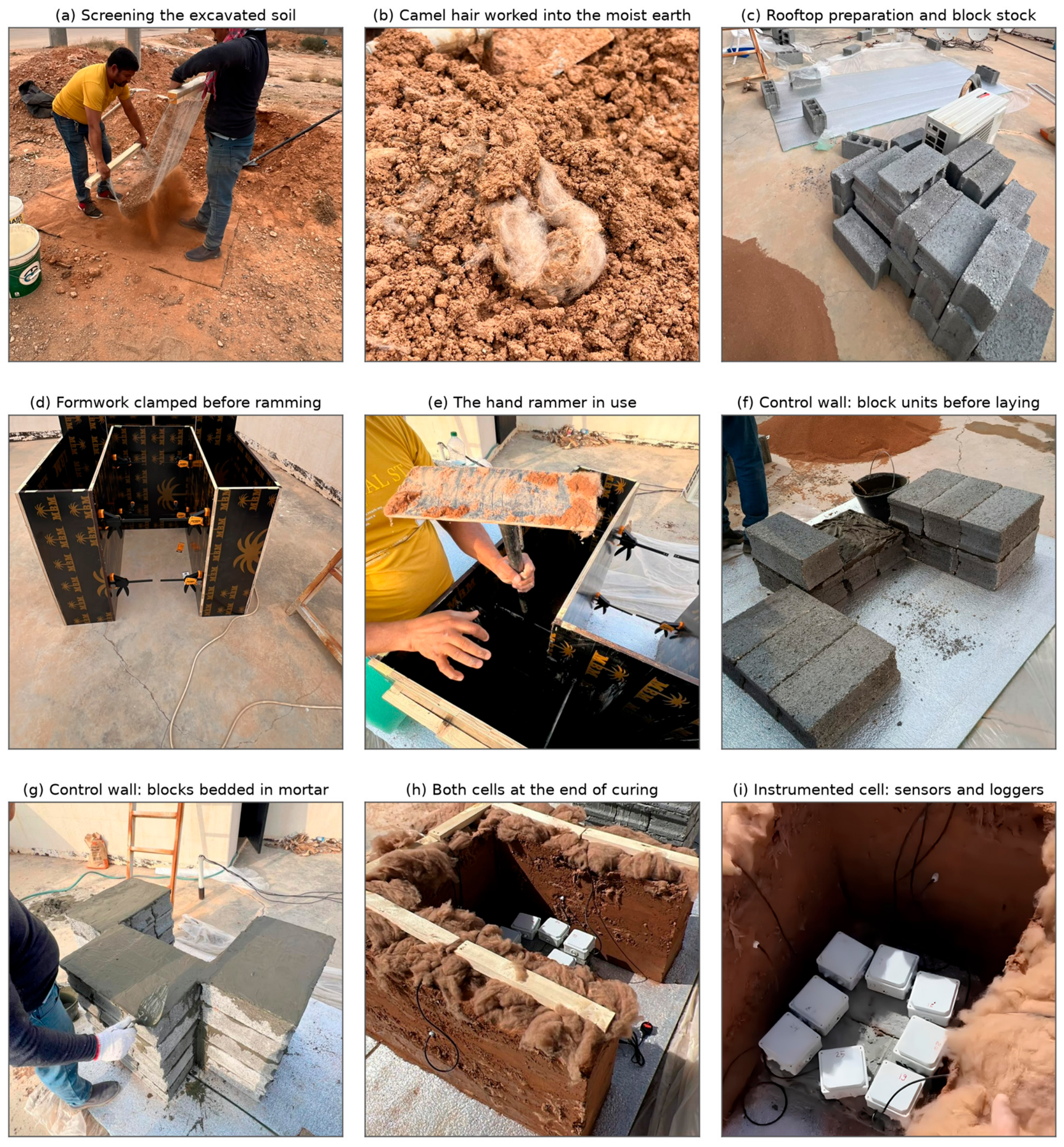
The earth used for the Room 1 walls was excavated locally at each site and screened on site through an aluminium mesh of 1.5 mm aperture, stretched on a timber frame and worked by hand, which retained gravel and oversize material and passed a finer sandy fraction (Figure 2a). The maximum particle size in the mix is therefore bounded at about 1.5 mm. No particle-size distribution, Atterberg limits, mineralogical analysis or moisture-content determination was carried out on the screened soil, either before mixing or from the completed walls. The soil is therefore described here only by its provenance and by the screening applied to it, and the assembly cannot be classified against the grading envelopes normally used to assess a soil for rammed-earth construction. This is carried into the limitations in Section 3.7, and it bears directly on the interpretation of the fibre: because the clay fraction that would ordinarily supply cohesion is unquantified, the relative contributions of matrix cohesion and fibre reinforcement to the integrity of these walls cannot be established from the present data. Cleaned camel hair was then opened by hand and worked into the moist earth in successive additions (Figure 2b) until the fibre was visibly distributed through the matrix without clumping (Figure 2c). The mix was brought to a moist, friable consistency suitable for compaction rather than to a plastic or pourable state.
The rooftop working area was prepared by laying polythene sheeting covered with a reflective foil-faced insulation mat, weighted at the edges with hollow blocks, so that the cells were thermally and hygrically decoupled from the roof slab beneath them (Figure 2d). The same figure shows the stock of hollow concrete blocks used for the Room 2 walls. Formwork for the earth walls was assembled from film-faced plywood panels held by quick-grip clamps, arranged to form the three wall cavities of the U-shaped plan in a single setting (Figure 2e). The mix was placed and compacted in six successive lifts of 150 mm compacted thickness, accounting for the full 900 mm wall height, each lift receiving a minimum of four rammer blows over every plate-area of its surface before the next was charged. Compaction used a purpose-made hand rammer with a flat rectangular steel head of 300 × 100 mm and 20 mm thickness, mounted on a vertical shaft and operated manually from above by one worker (Figure 2f). The head alone therefore has a mass of approximately 4.7 kg, computed from those dimensions and the density of steel; the mass of the complete tool including its shaft was not weighed, and the drop height was not controlled, so the compaction energy delivered per blow is bounded rather than known. The wall faces were left bare on both sides and remained so throughout monitoring. The crown was not. After the formwork was struck, a camel-hair layer was laid over the 1.17 m2 wall crown of the rammed-earth cell, retained by timber members, and instrumented with a sensor above and a sensor below it; the crown of the concrete-block cell carried a single bare surface sensor. That arrangement was in place for the whole campaign, because the crown served as the test surface for a separate assessment of camel hair as roof insulation, as explained in Section 2.2. The two cells therefore differ at the crown as well as in their wall material, and Section 4.7 quantifies that difference and bounds its effect on the wall measurement.

2.5. Camel-Hair Material

The camel hair used as reinforcing fibre within the rammed-earth mix was raw fibre purchased in bales from a commercial supplier, with stated place of origin as Hebei, China. The supplier’s declared specification is a staple length of 30–50 mm and a fineness of about 19 µm; these are reported here as provenance rather than as characterisation, because they were not verified independently, because the declaration is internally inconsistent on both quantities, and because the material as delivered was coarse raw hair rather than the fine dehaired grade a 19 µm fineness would denote. The fibre was opened by hand before mixing and was combined with the screened soil at a ratio of 20:1 soil to fibre by loose volume before compaction; the proportion by dry mass was not determined. The fibre was supplied already cleaned and treated by the manufacturer and was used as received; no washing, scouring or other treatment was carried out by the authors, and the processing applied by the supplier was not specified to us. The regional abundance of camel hair motivates its investigation, but the fibre used in these walls was not locally sourced. Laboratory determination of thermal conductivity and the sorption isotherm for this specific fibre batch was outside the scope of the present campaign. Where a property value is required for interpretation, published ranges for camel and sheep fibre are adopted [4,21,24], and this substitution is carried explicitly into the limitations in Section 4.7.

2.6. Instrumentation and Data Acquisition

Each measurement node used a Sensirion SHT35 digital temperature and humidity sensor (Sensirion AG, Stäfa, Switzerland), with typical accuracy of ±0.1 °C and ±1.5% relative humidity, read by an internet-connected ESP32 microcontroller (Espressif Systems, Shanghai, China) that posted readings to cloud spreadsheets at a nominal 15-min interval. The campaign as a whole comprises 36 sensor numbers, of which 34 were populated; Table 2 sets out the complete scheme so that the accounting is explicit. Twenty-four of them are analysed in this paper: at Taif, S1–S6 on the rammed-earth walls and S9–S14 on the concrete-block walls; at Riyadh, S19–S24 and S27–S32 respectively. The remaining ten populated channels measure the roof assemblies of both cells and a third wall type, hollow concrete block with camel-hair-filled voids, built as a south wall at each site; they fall outside the scope of the present paper, which concerns the two wall assemblies only, and are not analysed here. Sensor numbers S18 and S36 were unused and contain no records. Within each group the odd-numbered sensor of a pair is the outer face and the even-numbered sensor the inner face, ordered west, south, east. Sensors were mounted in contact with the wall surface at mid-height, approximately 450 mm below the crown and 450 mm above the base, on the centre-line of each wall. Outer sensors were exposed to direct solar radiation without dedicated radiation shielding and therefore report a surface microclimate rather than shielded air temperature; this is treated throughout as a measurement caveat rather than as an ambient measurement. The campaign began on 30 January 2026 at Riyadh and 1 February 2026 at Taif. The Taif cells were still logging at the analysis cut-off of 30 July 2026, whereas the Riyadh nodes ceased between 14 and 18 July 2026.

2.7. Data Quality Control and Analysis Windows

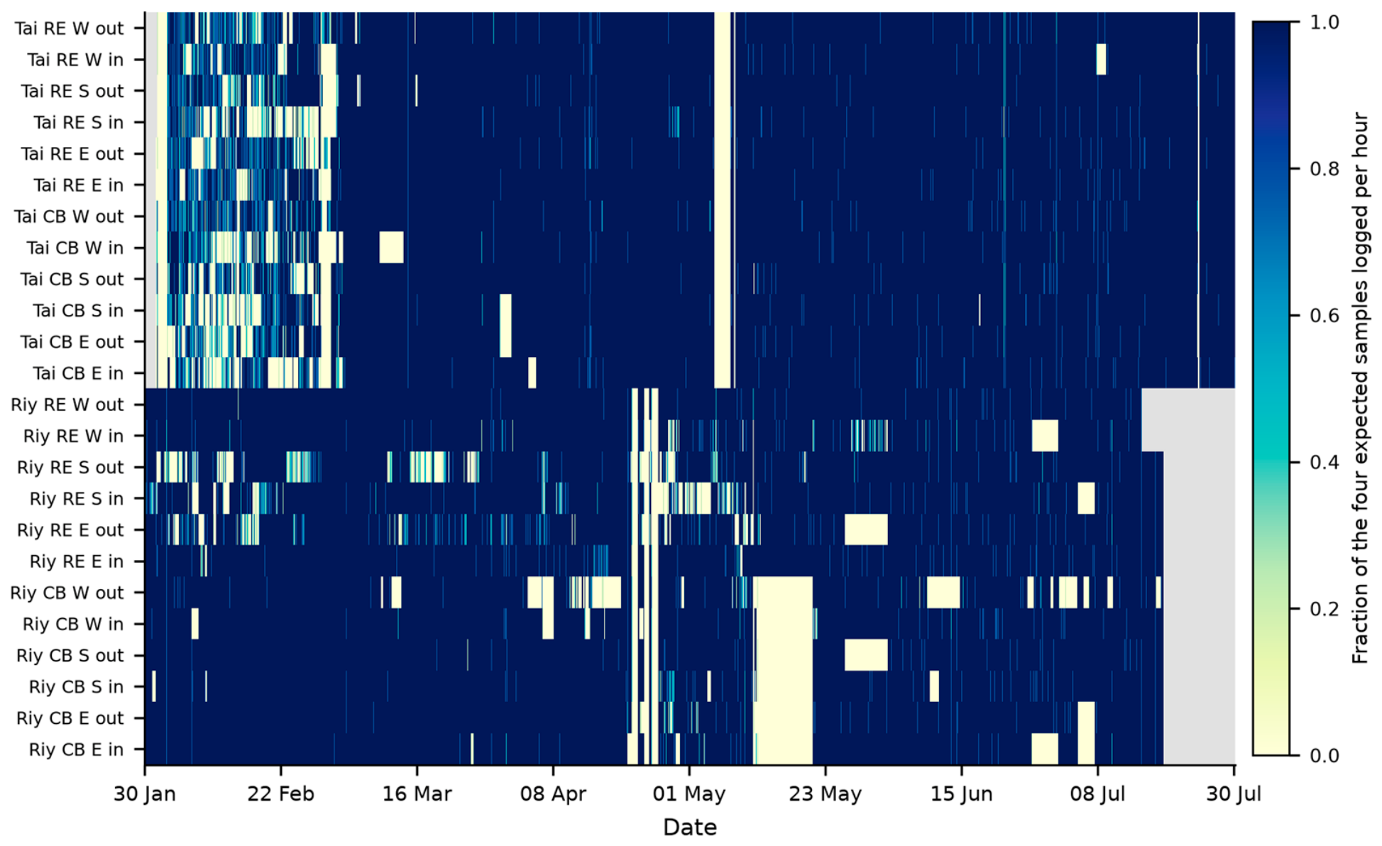
Logging was not continuous: storms and site power interruptions produced gaps. Each series was loaded, sorted chronologically, stripped of duplicate timestamps and screened for physically implausible values against the sensor’s stated range. Any interval longer than 45 min between consecutive readings was flagged as a gap. Across the 34 populated channels of the campaign, mean uptime was 90.8%, ranging from 75.9% (S27, Riyadh concrete-block west outer) to 98.0% (S19, Riyadh rammed-earth west outer). Two sensor numbers, S18 and S36, were unused placeholders and contained no records. Two site-wide outages dominate the record: Taif lost all channels for about 67 h from 5 to 8 May 2026, and Riyadh lost all channels for about 217 h from 12 to 21 May 2026. A cluster of shorter interruptions affected Taif through late February and early March. Figure 3 maps hourly coverage for the 24 wall sensors.
Because the twelve wall pairs are physically independent, each pair was analysed over its own common window, defined as the period during which both of its sensors were live. This preserves the longest usable record for every comparison instead of truncating all walls to the shortest one; the windows and their coverage are listed in Table 3. Within each window both series were regridded to a regular 15-min grid by snapping samples to the nearest grid point and removing duplicates. Interruptions of 30 min or less were bridged by time interpolation; longer gaps were left empty and excluded from all statistics. For daily metrics, any day with fewer than 80 valid paired samples was dropped, and days on which the outer-face amplitude fell below 1 °C were excluded from ratio-based metrics because the denominator becomes unstable. This procedure yielded 1708 analysed wall-days in total.

2.8. Performance Metrics

Four families of metrics were computed for every wall pair. The across-wall temperature difference ΔT = T_outer − T_inner quantifies the instantaneous temperature difference across the assembly. Because its sign reverses between day and night, it was additionally averaged separately over daytime (10:00–17:00) and night (22:00–05:00) hours. The decrement factor DF is the ratio of the daily inner-face temperature amplitude to the daily outer-face amplitude, computed per day, with lower values indicating stronger damping [26]. The thermal time lag is the interval between the daily outer-face peak and the daily inner-face peak, wrapped to the range −6 h to +18 h. For moisture, relative humidity was converted to absolute humidity AH in g m−3 through the Magnus saturation relation, so that actual vapour content rather than temperature-dependent relative humidity is compared across the wall:
es = 6.112 exp[17.62 T/(243.12 + T)];   e = (RH/100) es;   AH = 216.67 e/(T + 273.15)
where es is saturation vapour pressure in hPa, e is vapour pressure in hPa, T is temperature in °C and RH is relative humidity in percent. DF and time lag are reported as means ± one standard deviation over the analysed days.
Three deliberate choices in this metric definition should be noted. First, the descriptors are computed on surface temperature rather than heat flux, for the reason given in Section 1.1: no heat-flux plates were installed, and surface temperature is what the instrumentation measures directly. Second, the decrement factor is computed per day and then averaged, rather than computed once on a season-long mean profile; this preserves the day-to-day dispersion that is reported alongside every mean and prevents a small number of extreme days from dominating the statistic. Third, the time lag is obtained from the timing of the daily maxima rather than by harmonic decomposition. The latter is more robust to noise but assumes a sinusoidal forcing, which the measured surface record is not, particularly on days with intermittent cloud. The consequence is that individual daily lag values are noisier than a harmonic estimate would be, which is visible in the standard deviations reported in Table 4, and it is one reason the paired day-matched comparison is preferred over the difference of means when the two materials are compared.

2.9. Paired Comparison and the Construction-Dry Period

Because the two wall types at a given site and orientation experienced identical weather, materials were also compared in a strictly paired sense. For every calendar day on which both the rammed-earth pair and the concrete-block pair yielded a valid daily metric, the difference between them was formed, and the mean, standard deviation and the fraction of days favouring the earth wall are reported. This removes day-to-day weather variability from the material comparison and is the primary basis on which the material claim in this paper rests.
Separately, because a freshly built rammed-earth wall releases construction water over a period of months, all hygric comparisons are reported both over the full record and restricted to 1 June 2026 onwards, by which point the drying curve presented in Section 3.7 has flattened. The latter is treated throughout as the construction-dry condition, and all quantitative hygric claims are made on that basis.

3. Results

3.1. Boundary Conditions

The measured outer-face record confirms the intended climatic contrast. Averaged over the three exposed wall faces of each cell, mean outer-surface temperature was 26.0 °C at Taif and 31.6 °C at Riyadh. Riyadh imposed the stronger diurnal forcing, with a mean daily outer-surface swing of 17.0 ± 3.5 °C against 11.8 ± 2.5 °C at Taif, and drier air, with mean outer-face relative humidity of 39.1% against 47.6%. The highest single outer-surface reading of the campaign was 63.2 °C, on the Riyadh concrete-block west wall, compared with 46.3 °C on the Taif rammed-earth south wall. Minimum outer-surface temperatures were effectively identical at the two sites, both close to 10.4 °C, so the difference between the sites is one of daytime loading rather than of night-time cooling. The hottest recorded day was 17 June at Taif and 16 July 2026 at Riyadh; because the campaign extended through mid-summer, peak-season conditions are captured at both sites.
The inner faces of the cells are not shaded surfaces, and Section 2.3 predicts on geometric grounds that two of the three receive a substantial direct-beam load. The measured record provides an independent test, because expressing each inner face as a departure from the mean of the three inner faces of its own cell removes the common diurnal cycle and leaves the orientation-specific component (Figure 4). At Riyadh in June and July, the pattern follows the calculation closely: the west inner face runs 1.6 to 1.8 K warmer than its siblings at 07:00 and falls steadily thereafter, while the east inner face is 1.3 to 1.9 K cooler at 07:00 and rises to 0.7 K warmer by mid-afternoon. Both cells show the same pattern with the same timing, as a geometric effect common to both should. The south inner face shows no positive daytime departure at either site, as its northward orientation requires. At Taif the pattern is weak and the west face departs from it, which is consistent with the shading of that facade identified independently in Section 3.6 and which would invalidate the unobstructed-sky assumption the calculation makes. The orientation-specific component is of order 2 K peak-to-peak, against inner-face daily swings of 4.7 to 12.5 K: a real part of the inner boundary condition, but not the dominant one, and one that is shared by the two cells at a site and so largely cancels in the paired difference.

3.2. Diurnal Behaviour of the Two Wall Types

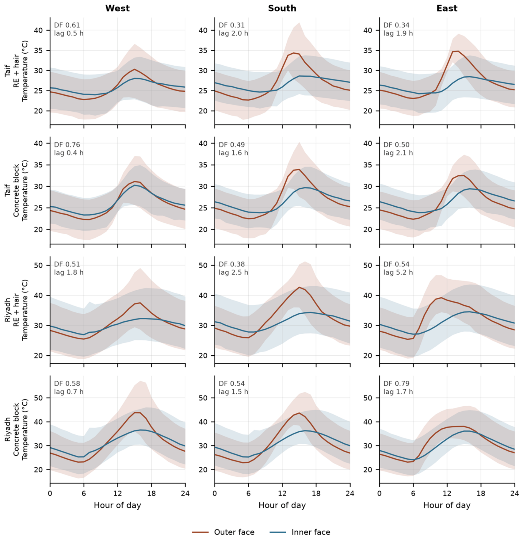
Figure 5 shows the mean diurnal outer- and inner-face temperature for all twelve wall pairs. The qualitative pattern is consistent everywhere. The outer face rises steeply through the morning to a sharp afternoon maximum, while the inner face follows a much flatter curve that peaks later and lower. The two traces cross in the late afternoon or early evening, after which the inner face remains the warmer of the two until sunrise. The rammed-earth panels (rows 1 and 3) show visibly flatter inner-face curves than the concrete-block panels (rows 2 and 4) at the same site and orientation. This is the qualitative signature of the quantitative damping advantage established below, and it is visible before any statistic is computed.

3.3. Amplitude Damping: Decrement Factor

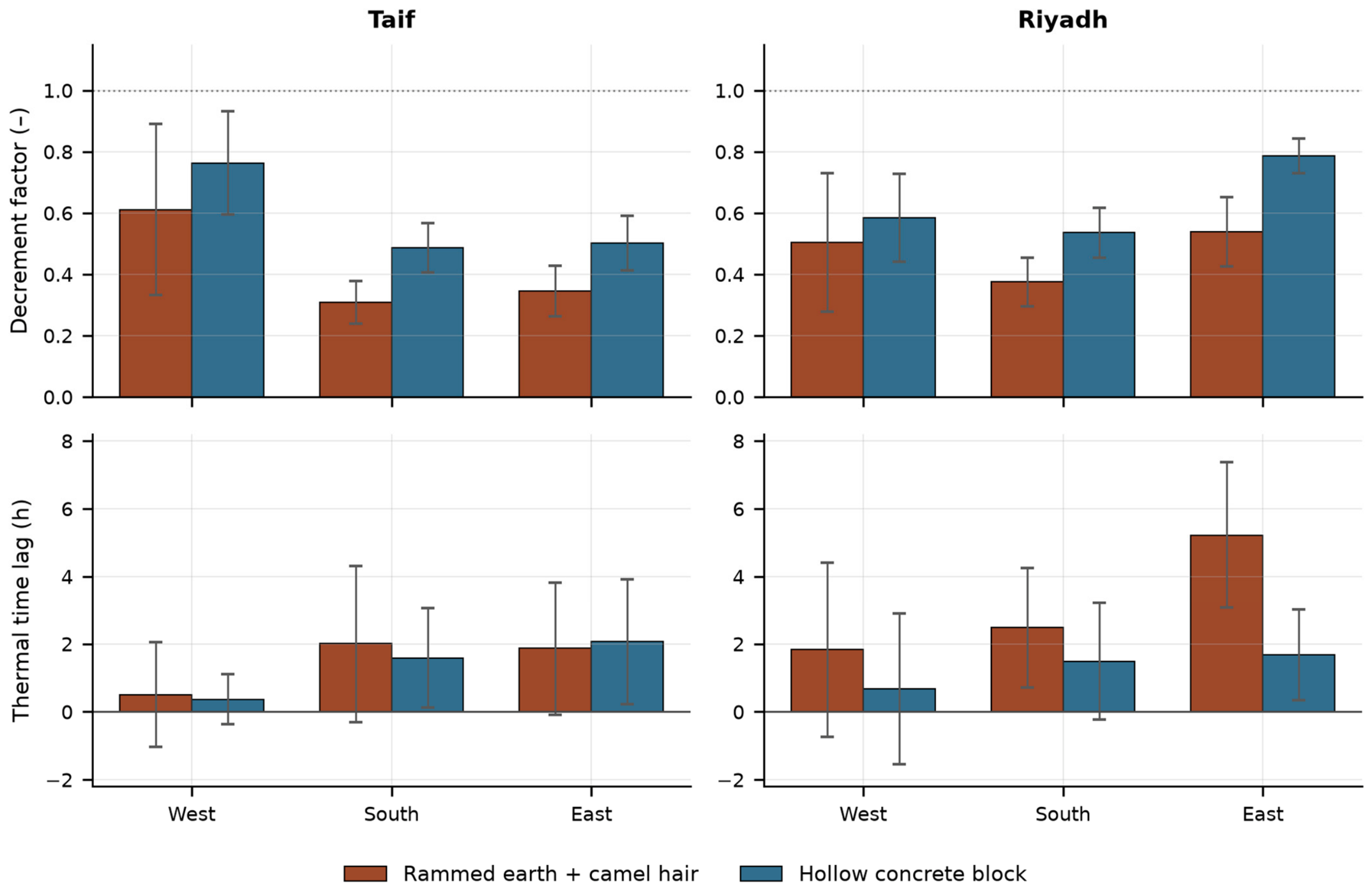
The rammed-earth-plus-camel-hair wall damped the daily temperature swing more strongly than hollow concrete block in every one of the six site–orientation combinations. Averaged over the three orientations, the mean decrement factor was 0.422 for the earth wall against 0.584 for concrete block at Taif, and 0.473 against 0.636 at Riyadh (Figure 6, Table 4). In physical terms the inner-face temperature amplitude of the earth wall was 42–47% of its outer-face amplitude, against 58–64% for concrete block. Because no heat-flux plates were installed, this ratio quantifies attenuation of the temperature oscillation only and does not describe the fraction of heat transmitted through the wall.
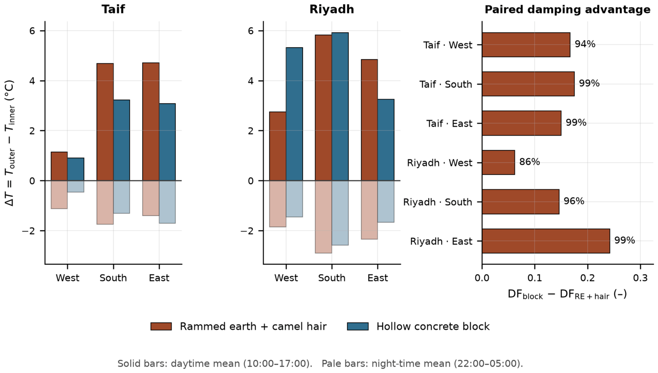
Because both walls at a site and orientation saw the same weather, the comparison was also made day by day on matched dates (Figure 7, right panel; Table 5). The earth wall damped more strongly on 86–99% of matched days, with the paired difference in decrement factor ranging from 0.062 ± 0.152 on the Riyadh west wall to 0.242 ± 0.095 on the Riyadh east wall. The consequence for the interior surface is substantial: the mean inner-face daily amplitude was 7.0 °C for the earth wall against 12.5 °C for concrete block at Riyadh, and 4.7 °C against 6.8 °C at Taif. Peak inner-surface temperature over the whole campaign was correspondingly lower for the earth wall in every case, by 0.4–3.3 °C depending on site and orientation. The largest margin was on the Riyadh west wall, 45.9 °C against 49.2 °C; the smallest was on the Taif east wall, where the two were nearly equal at peak, 36.9 °C against 37.4 °C.
The dispersion of the paired difference is as informative as its mean. On the four strongly and predictably loaded orientations—both south walls and both east walls—the standard deviation of the daily difference in decrement factor is small relative to its mean: 0.069 against 0.175 at Taif south, and 0.095 against 0.242 at Riyadh east. There the earth wall damps more strongly on essentially every analysed day. On the two west walls, the dispersion is larger relative to the mean (0.219 against 0.167 at Taif; 0.152 against 0.062 at Riyadh), and the fraction of days favouring the earth wall falls accordingly. This is consistent with the reduced and less regular solar loading identified on those facades in Section 3.6, and it means the west-wall result should carry less weight than the other four in any overall assessment.
The advantage was not present from the beginning of the campaign, and the way it emerged is itself a result. At Riyadh in February, when the outer face of the rammed-earth wall still stood at a monthly mean relative humidity of 95.8%, its decrement factor was 0.66 against 0.69 for concrete block, an advantage of 0.03 that is negligible. Over the following months the earth wall fell to 0.49 in March, 0.44 in April and 0.42 by July, while the concrete-block wall moved only from 0.69 to 0.58; the advantage therefore established itself at 0.16–0.18 from March onwards and was stable thereafter. The time lag behaved the same way: the earth wall led the concrete-block wall by 0.08 h in February and by 1.6–3.4 h in every subsequent month. This progression follows the construction-drying curve of Section 3.7 and not the imposed forcing, which varied between about 15 and 20 °C of mean daily outer-surface swing across the same months without trend; the correlation between the monthly lag advantage and the monthly imposed swing is in fact slightly negative. At Taif, where monthly sampling begins in March with the wall already below 84% relative humidity, the advantage is 0.13–0.20 throughout and shows no comparable transient. A saturated earth wall therefore damps little better than concrete block, and the benefit reported in this paper is a property of the wall once dry.

3.4. Thermal Time Lag

Time lag separated the two climates far more sharply than damping did. At Riyadh the rammed-earth wall delayed the inner-face peak by 3.2 h on average, against 1.3 h for concrete block, and it showed the longer lag on 65–96% of matched days. At Taif the two materials were indistinguishable: 1.5 h against 1.3 h, and the day-by-day comparison favoured the earth wall on only 32–51% of matched days, which is no better than chance. The pattern mirrors the boundary conditions: at the arid site the outer surface is driven through a swing half again as large as at Taif, and it is under that stronger forcing that the additional heat capacity and fibre resistance of the earth wall translate into a measurable phase shift as well as an amplitude reduction.

3.5. Across-Wall Temperature Difference, Day and Night

The across-wall temperature difference reverses sign between day and night at every wall (Figure 7). Averaged over daytime hours the outer face was warmer than the inner face by 3.51 °C for the earth wall and 2.40 °C for concrete block at Taif, and by 4.47 °C and 4.83 °C respectively at Riyadh. At night the temperature difference reverses. At Taif the inner face remained warmer by 1.42 °C for the earth wall, compared with 1.16 °C for the concrete block, and at Riyadh by 2.36 °C against 1.90 °C. This is the expected consequence of thermal storage combined with radiative cooling of the exposed surface to the night sky, and it is stronger for the earth wall at both sites, consistent with its greater heat capacity. Extreme instantaneous temperature differences reached 14.2 °C at the 99th percentile on the Riyadh concrete-block west wall.
The night-time reversal is worth dwelling on because it is easy to misread. A wall whose inner face is warmer than its outer face at night is not failing; it is returning heat stored during the day, while its exposed surface loses heat rapidly to a clear desert sky by longwave radiation. In an occupied building this stored heat is a liability in summer, since it prolongs the cooling requirement into the evening, and an asset in winter, since it sustains internal surface temperatures overnight. The present cells cannot distinguish these consequences because they have no conditioned interior and no occupancy; the magnitude of the reversal is consistently larger for the earth wall, and largest of all on the Riyadh rammed-earth south wall. It is a qualitative signature of storage and release, and of the same property that produces the phase shift reported in Section 3.4. It is not a measure of the energy cycled. Quantifying that would require the volumetric heat capacity of the section, the temperature field through it and the boundary heat fluxes, none of which was measured here.

3.6. Effect of Orientation

Pooling both materials, orientation ordered the walls consistently by solar loading. At both sites the south wall carried the largest mean outer-face amplitude (14.1 °C at Taif, 20.3 °C at Riyadh) and the largest daytime across-wall temperature difference (3.96 °C and 5.87 °C). It also produced the lowest decrement factors (0.398 and 0.456), which is expected: the same wall damps a larger imposed swing proportionally more effectively.
Two orientation results require care rather than physical interpretation, and are reported here rather than smoothed away. The Taif west walls show an unusually small outer-face amplitude (9.4 °C, against 14.1 °C on the south) and a mean-diurnal peak no later than that of the south wall, which is not consistent with an unobstructed west facade and indicates partial shading or a protected sensor mounting at that location. The correspondingly high pooled decrement factor there (0.687) should therefore be read as a consequence of the small denominator, not as poor wall performance. The Riyadh east walls show the campaign’s longest apparent lag (3.45 h pooled, 5.22 h for the earth wall) because the outer face of an east wall peaks in mid-morning whereas its inner face, which looks west across an open-ceilinged cell, receives direct sun in the afternoon. That value therefore combines a genuine conduction lag with a difference in solar exposure between the two faces and should not be read as conduction alone.

3.7. Hygric Performance and Construction Drying

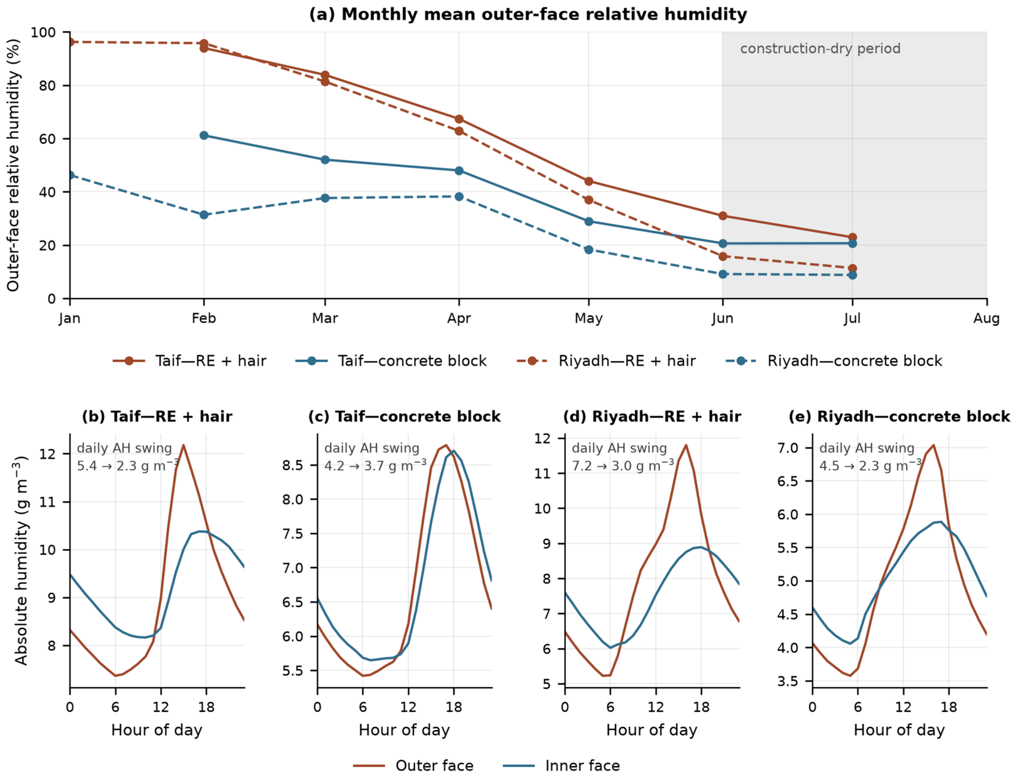
Relative humidity at the rammed-earth walls began the campaign close to saturation and fell monotonically for five months (Figure 8a). The three-wall mean outer-face relative humidity declined from 93.9% in February to 22.9% in July at Taif, and from 96.2% in January to 11.5% in July at Riyadh. The concrete-block walls started far lower and fell much less, from 47.8% to 8.7% in Riyadh. Several rammed-earth channels saturated during this phase, with up to 9.1% of samples on an individual channel pinned at 100% relative humidity, against at most 0.3% on any concrete-block channel. This is the signature of the construction water placed in the wall during ramming, leaving the fabric over a period of months. It means that no comparison of absolute humidity level between the two rooms is physically meaningful until the curve flattens, and all hygric statistics below are accordingly restricted to 1 June 2026 onwards.
Within that construction-dry period, the informative result is not the mean humidity level but the damping of its daily cycle (Figure 8b–e). The rammed-earth wall reduced the daily absolute-humidity swing from 5.4 to 2.3 g m−3 at Taif, a reduction of 57%, and from 7.2 to 3.0 g m−3 at Riyadh, a reduction of 58%. The concrete-block wall achieved only 4.2 to 3.7 g m−3 at Taif, a reduction of 11%, although at Riyadh it reached 4.5 to 2.3 g m−3, or 48%. Mean vapour content across the earth wall was nearly balanced in the dry period (9.0 against 9.2 g m−3 at Taif; 7.8 against 7.6 g m−3 at Riyadh), so the wall is not acting as a net vapour source or sink at that stage but as a buffer that flattens the cycle. The residual offset in absolute level between the two rooms is addressed in Section 4.7.

3.8. Performance on the Hottest Recorded Day

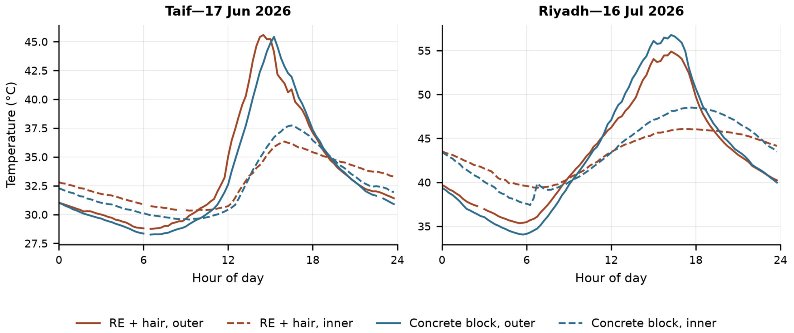
Figure 9 shows the southern-wall profiles on the hottest day at each site. At Riyadh on 16 July 2026 the concrete-block outer surface reached 56.8 °C and drove its inner face to 48.5 °C, whereas the earth wall’s outer surface peaked at 54.9 °C and its inner face at 46.1 °C—an advantage of 2.45 °C at the interior surface under the most demanding conditions of the campaign. The Taif case is more instructive still. On 17 June the two outer surfaces were within 0.2 °C of each other (45.6 °C and 45.4 °C), yet the earth wall held its inner face 1.40 °C cooler (36.3 °C against 37.7 °C). Because the imposed load was effectively identical, this approximates a controlled comparison of the two assemblies under peak conditions. In both cases the earth wall’s inner trace is flatter through the day and stays warmer overnight, the same storage-and-release behaviour seen in the seasonal means.

3.9. Summary of Metrics

The metrics underlying the preceding sections are collected in three tables. Table 4 reports every wall pair over its own analysis window, so that each of the twelve comparisons can be inspected individually. Table 5 gives the paired, day-matched comparison between the two wall types at each site and orientation, which is the basis of the material claim made in this paper. Table 6 averages over the three orientations to give one figure per site and wall type, and is the source of the summary values quoted in the Abstract and in Section 4.

4. Discussion

4.1. Mechanism of the Damping Advantage

The central result is that a wall of camel-hair-reinforced rammed earth damps the daily temperature swing more effectively than hollow concrete block in every orientation at both climates tested, and that the advantage survives a strictly paired, day-matched comparison on 86–99% of days. Mechanistically this is what the combination should deliver. The earth matrix contributes volumetric heat capacity that absorbs energy during the day and releases it at night, while the fibre distributed through that matrix introduces low-conductivity, air-filled inclusions within it—the same mechanism reported for keratin fibres at material scale [21,22,23,24] and exploited in wool-reinforced earthen composites [11,18,19]. The hollow concrete block, by contrast, has lower heat capacity per unit wall area and its voids are air-filled cavities large enough to convect, so it neither stores nor resists as effectively.
The magnitudes deserve careful framing. Decrement factors of 0.42–0.47 for the earth wall are considerably higher—that is, less damping—than the 0.19–0.26 reported for a 0.29 m uninsulated rammed-earth wall and the sub-0.15 values for a 0.37 m wall in long-term in situ measurement [8], and higher than the 0.12–0.15 reported for modified rammed earth [9]. The obvious explanation would be wall thickness, but it does not apply here: the present walls are 300 mm thick, within 4% of the 290 mm wall in that in situ study. Thickness is effectively controlled, and the difference must lie elsewhere.
The explanation we consider most plausible is the boundary condition on the inner face. In the cited studies the inner face bounds an enclosed, occupied interior, so it responds almost exclusively to heat conducted through the section. In the present cells the interior is a 900 × 1200 × 900 mm void that is open to the sky and open along its north side; the inner face is therefore washed by outdoor air and exchanges longwave radiation with the sky directly. It is driven by ambient conditions through two paths, only one of which is conduction through the wall. Both consequences follow immediately: the inner-face amplitude is larger than conduction alone would produce, raising the decrement factor, and its peak is pulled towards the ambient peak, shortening the apparent time lag. A secondary contribution is geometric. The wall is only three times its own thickness in height and five times in plan length, so heat entering through the exposed top edge and the corners is not negligible relative to one-dimensional flow through the section. The geometry therefore departs from the one-dimensional idealisation that the decrement-factor definition assumes [26,27].
This reading matters for how the absolute numbers in this paper should be used. The decrement factors and time lags reported here are not the values a 300 mm camel-hair-reinforced earth wall would exhibit in an enclosed building; they are almost certainly conservative, since an enclosed interior would remove the parallel path and leave conduction alone. They should be treated as a comparative index measured under a common, deliberately severe boundary condition, not as transferable wall properties—which is exactly the distinction the comparative test-cell literature draws [31]. What does transfer is the ranking and the size of the gap between the two assemblies, because both were subject to the same geometry, the same sky and the same air on the same days. Testing the same walls in enclosed cells is the single most valuable next step, and would be expected to lower both decrement factors towards the dwelling-scale literature values while preserving the material difference.
The contribution of the camel hair itself cannot be isolated from these measurements, and it is important to be exact about why. The fibre is distributed within the earth matrix and the wall carries no applied layer, so the comparison made here is between fibre-reinforced rammed earth and hollow concrete block—two assemblies that differ in matrix, density, void structure, surface finish and construction method at once. No result in this paper can therefore be attributed to camel hair rather than to the change of wall material. The control that would isolate it is an unreinforced rammed-earth cell built and instrumented alongside the others, which this campaign does not contain, and that is the clear priority for follow-up work.
The record does, however, separate a surface effect from a sectional one, and this is worth stating because the two are often conflated. On the hottest Taif day, the two outer surfaces were within 0.2 °C of one another while the inner faces differed by 1.40 °C, which isolates the response of the section under an almost identical imposed load. On the Riyadh west wall, by contrast, the outer faces themselves differed by 9.6 °C—63.2 °C for concrete block against 53.6 °C for the earth wall—which is a difference in the load imposed on the wall rather than in transmission through it. Since neither wall carries an applied surface layer, that difference must arise from the properties of the two exposed surfaces themselves: solar absorptance, colour, emissivity and residual moisture content. None of these was measured, so this is offered as the most plausible reading of the difference rather than as a demonstrated mechanism.

4.2. Climate Dependence of the Phase Behaviour

The most practically useful finding is that damping and phase shift do not travel together. At Riyadh the earth wall delayed the inner-face peak by 3.2 h against 1.3 h for concrete block, whereas at Taif the two materials were indistinguishable at about 1.5 h. Damping, by contrast, was present at both sites and in every orientation. The natural interpretation is that a measurable phase shift emerges only once the imposed swing is large enough for storage to dominate the wall’s response: Riyadh’s mean outer-surface swing of 17.0 °C is half again Taif’s 11.8 °C. This is consistent with the established sensitivity of decrement factor and time lag to boundary conditions rather than to material properties alone [27,28].
For designers the implication is specific. The amplitude benefit of this assembly can be assumed across hot climates, but the additional benefit of shifting the interior peak away from the late afternoon should be claimed only where diurnal forcing is strong—which is precisely where peak cooling demand is most expensive to serve, and therefore where the benefit is worth most. A wall specification justified on phase-shift grounds in Riyadh should not be assumed to deliver the same benefit in Taif.

4.3. Orientation and the Geometry of the Test Cells

Orientation behaved as solar geometry predicts where the walls were unobstructed, with south facades carrying the largest amplitudes and temperature differences and the lowest decrement factors at both sites. Two departures were identified in Section 3.6, and both follow from the open test-cell geometry rather than from material behaviour.
The Taif west walls recorded an outer-face amplitude far below the south walls with no later peak, which is not physically consistent with an exposed west facade and points to shading or protected sensor mounting. Their apparently poor decrement factors are an artefact of the small imposed swing that forms the denominator of the ratio. The Riyadh east walls produced the campaign’s longest apparent lag because an east wall’s outer face peaks in mid-morning while its inner face, exposed to the sky through the open ceiling and the open north side, is itself directly sunlit in the afternoon. Neither case invalidates the material comparison, which is made between two walls of the same orientation at the same site and is therefore internally controlled, but both are a caution against reading any single time lag from an open cell as pure conduction. This is a concrete instance of the general point that dynamic wall metrics are properties of the wall and its boundary conditions jointly, not of the wall alone.

4.4. Construction Drying as a Result in Its Own Right

The humidity record contributes two distinct findings. The first is that the rammed-earth walls took approximately five months to shed their construction water, with outer-face relative humidity falling from near saturation to below 25% over that period while the concrete-block walls barely moved. This transient is a result in its own right for anyone commissioning, monitoring or certifying earth construction, and Section 3.3 shows that its consequences are thermal as well as hygric. While the Riyadh earth wall was still near saturation, it damped no better than concrete block, and its decrement-factor and time-lag advantages appeared only as it dried. The construction water is therefore not merely a confounder to be excluded from the humidity statistics: it suppresses the thermal benefit of the wall for as long as it is present. A commissioning measurement taken on a new earth wall will understate its performance, and by a margin large enough to change the conclusion. It means that hygrothermal measurements taken on a new earth wall within its first months describe the drying process rather than the material’s steady behaviour, and that any comparison of humidity level between a new earth wall and a masonry control during that window will be dominated by construction water. Studies reporting hygrothermal parameters of earth materials should state the age of the wall at measurement; this appears not to be standard practice.

4.5. Hygric Buffering After Drying

The second hygric finding is that once dry, the earth wall damped the daily absolute-humidity swing by 57–58%, against 11% for concrete block at Taif, while mean vapour content across the wall was nearly balanced. That combination—strong attenuation of the daily cycle with no net difference in vapour content—is the expected signature of hygroscopic buffering rather than of net moisture transport, and it is what the moisture-buffer-value framework was developed to describe [29,30]. It is consistent with the strong sorption of keratin fibres [4,6] and with the coupled heat and moisture behaviour reported for earthen envelopes [9,10,14].
The Riyadh concrete-block wall’s comparatively high moisture damping (48%) is worth noting as a caution against attributing all swing reduction to sorption. In very dry air the absolute-humidity cycle is small in absolute terms and is influenced by surface temperature as much as by vapour exchange, so the percentage reduction is a less discriminating statistic there. The contrast at Taif, where the earth wall damped 57% against the concrete-block wall’s 11% under the same conditions, is the cleaner demonstration of the buffering effect.

4.6. Practical Implications

For low-rise construction in hot regions, the results support a specific and bounded claim. In the configuration tested, a wall built from locally excavated earth reinforced with camel hair produced a lower and later inner-surface temperature than hollow concrete block of the same thickness in every orientation at both sites, with the mean inner-face daily swing reduced from 12.5 to 7.0 °C under arid conditions. Whether that difference survives in an enclosed, conditioned interior is untested here and requires enclosed-cell or building-scale measurement; the present cells are open and unconditioned, so the descriptors are comparative indices rather than transferable wall properties. Within those bounds the assembly and it will additionally stabilise the moisture content of the adjacent air. The soil for the earth wall was won on site and the wall requires no industrial insulation product, although the camel hair used here was imported rather than locally collected, so no claim of local sourcing is made for the assembly as tested. Given that the buildings sector must cut emissions sharply against a rising baseline [1], and that a large fraction of the regional housing stock is uninsulated block construction [2], an assembly assembled from a waste fibre and site-won soil is worth taking seriously even where its absolute decrement factor is modest.
The finding also generalises the emerging case for regional agricultural residues in envelope construction. Date palm waste has been shown to improve comfort and energy performance in arid-climate buildings [13]; camel hair appears to belong in the same category, with the added advantage that it functions both as a matrix stabiliser and as a surface insulation layer within a single wall.
Three caveats bound the practical claim. The walls tested are 300 mm thick, which is a realistic construction thickness for single-storey earth building, but they are unstabilised and were built as short, free-standing panels, so structural adequacy, rain erosion and long-term durability—the historic weaknesses of unstabilised earth—are outside what this campaign evidences; the fibre-reinforcement literature suggests improved crack behaviour [11,12,25] but says little about multi-year exposure. Biological durability of an animal fibre embedded in a moist matrix is likewise untested here and is identified in the bio-based insulation literature as the field’s weakest evidence base [3]. And because no cooling system was present, no energy or emissions saving is claimed: what is demonstrated is a lower and later interior surface temperature and a flatter moisture cycle, which are the physical preconditions for such savings rather than a measurement of them.

4.7. Limitations

Several limitations bound these conclusions and should be read alongside every number reported above.
  • First, and most importantly, the test cells are small—1500 × 1500 × 900 mm over outer faces, with a clear interior of only 900 × 1200 × 900 mm—and they have three walls, an open north side and no ceiling. The ‘inner’ face is therefore the surface of an unconditioned, freely ventilated, partly sunlit void, not the internal surface of an occupied room, and it is coupled to outdoor air and to the sky in parallel with conduction through the wall. As argued in Section 4.1, this raises the measured decrement factors and shortens the measured time lags relative to what the same 300 mm walls would give in an enclosed building. Absolute inner-surface temperatures are not indoor temperatures; no cooling-load saving should be inferred directly from them, and the dynamic descriptors should be read as a comparative index rather than as wall properties.
  • Second, outer sensors were unshielded and surface-mounted, so they report a surface microclimate influenced by colour, emissivity, and mounting detail rather than air temperature. No two facades are guaranteed identical in this respect, and the Taif west-wall anomaly is a likely instance.
  • Third, a residual difference of roughly 2 g m−3 in mean absolute humidity between the two rooms persists even in the construction-dry period. Part of this is plausibly real, since an earth wall remains hygroscopically active, but sensor-to-sensor calibration offset cannot be excluded. The moisture-swing damping reported here is robust to such an offset in a way that the absolute levels are not, which is why the swing is the statistic on which the hygric claim rests.
  • Fourth, the Riyadh concrete-block west channel (S27) retained only 75.9% uptime and its comparison rests on 112 analysed days, fewer than any other pair.
  • Fifth, the two cells at a site differ at the wall crown as well as in the wall material, and the size of that difference should be stated rather than assumed away. The crown of the rammed-earth cell carried a camel-hair layer under separate test as roof insulation, while the crown of the concrete-block cell was bare. Measured on the crowns themselves, the bare concrete-block crown reached a mean daily maximum of 51.9 °C at Taif and 50.7 °C at Riyadh against 37.6 °C and 46.7 °C beneath the camel-hair layer, and its mean daily swing was 24.5 K against 8.4 K at Taif and 19.2 K against 9.8 K at Riyadh. The crown is 1.17 m2 per cell, so this is not a trivial area. Two things bound its effect on the wall measurement. The mean crown temperatures differ by only 0.9 K at Taif and 0.1 K at Riyadh, so the steady component of the asymmetry is small; and a daily swing entering the top of the wall is attenuated with depth, with a diurnal damping depth of about 0.12 m for materials of this diffusivity, so at the sensor plane 450 mm below the crown only some 2.5% of it survives. The crown difference therefore contributes an order of 0.4 K at Taif and 0.2 K at Riyadh at the measurement height, against inner-face daily swings of 4.7 to 12.5 K. It acts in the direction that favours the earth wall and it has not been measured directly, so it is reported here as a bounded systematic difference between the cells rather than as a quantified correction.
  • Sixth, there are no replicate cells, so cell-to-cell workmanship is confounded with material. A single pair of cells per site cannot separate the effect of the wall system from the effect of how that particular wall was built.
  • Seventh, neither constituent of the earth wall was characterised in the laboratory. Thermal conductivity, density and sorption properties of the camel-hair batch and of the earth–fibre composite were not measured, so the mechanistic interpretation relies on published values for comparable fibres. Nor was the soil itself analysed: no particle-size distribution, Atterberg limits or mineralogy were determined, so the material cannot be placed within the grading envelopes conventionally used to judge a soil suitable for rammed earth. A further consequence follows for the site comparison specifically. The soil was excavated locally at each site rather than drawn from a single batch transported to both, so the Riyadh and Taif earth walls may differ in their soil as well as in their climate, and the between-site differences reported here cannot be attributed to climate alone. The within-site comparison between the earth wall and the concrete-block control, on which the material claim of this paper rests, is unaffected, because both cells at a site share the same weather and each wall type is built from the same material at that site.
  • Eighth, the record covers late winter through mid-summer at both sites. The winter heating case, in which a high-mass wall behaves differently, and the full annual cycle remain untested.

5. Conclusions

This six-month, two-climate field study instrumented both faces of every wall of paired test cells to compare a camel-hair-reinforced rammed-earth wall against hollow concrete block at an identical 300 mm thickness, resolving the comparison by orientation and by climate over 1708 analysed wall-days. Five conclusions follow.
(1)
The earth wall damped the daily temperature swing more strongly than concrete block in all six site–orientation combinations: mean decrement factors of 0.42 against 0.58 at Taif and 0.47 against 0.64 at Riyadh, holding on 86–99% of matched days. Mean inner-face amplitude fell from 12.5 to 7.0 °C at Riyadh and from 6.8 to 4.7 °C at Taif, and peak inner-surface temperature was 0.4–3.3 °C lower. The amplitude benefit is robust across orientation and climate.
(2)
Thermal time lag distinguished the two climates rather than the two materials. In arid Riyadh the earth wall delayed the inner peak by 3.2 h, compared with 1.3 h for concrete block; in milder Taif the materials were indistinguishable. A phase benefit should therefore be claimed only where diurnal forcing is strong, which is also where peak demand is most costly to serve.
(3)
The rammed-earth walls required approximately five months to release their construction water, after which they damped the daily absolute-humidity swing by 57–58% against 11–48% for concrete block, with no net difference in vapour content across the wall. The drying transient is itself a finding relevant to the monitoring and commissioning of earth construction.
(4)
The absolute values reported here are comparative indices, not wall properties. At 300 mm these walls match the published in situ rammed-earth literature in thickness, yet their decrement factors are roughly twice as high and their time lags several times shorter; the most plausible cause is the inner-face boundary condition of small, open, unconditioned cells. Dynamic descriptors measured in such cells are properties of the wall and its boundary conditions jointly, and the Riyadh east-wall lag and the Taif west-wall decrement factors are exposure artefacts that would mislead if quoted in isolation.
(5)
The paired, day-matched comparison is markedly more robust than a difference of seasonal means. It removes weather variability, exposes the dispersion of the effect as well as its magnitude, and shows here that the material advantage holds on almost every individual day rather than only on average.
Priorities for follow-up follow directly from these limits: enclosed and conditioned cells so that interior conditions and cooling loads are measured rather than inferred; heat-flux instrumentation alongside surface temperature; laboratory characterisation of the soil, the fibre and the earth–fibre composite; an unreinforced rammed-earth cell so that the contribution of the camel hair can be isolated; replicate cells to separate workmanship from material; and a full annual cycle including the winter heating case. A lower embodied carbon remains a plausible advantage indicated by the bio-based materials literature [3] rather than demonstrated here: no life-cycle assessment was performed, and the camel hair used in these walls was imported rather than locally collected.

Author Contributions

Conceptualisation, L.A.; methodology, L.A. and K.A.; software, K.A.; validation, K.A.; formal analysis, K.A.; investigation, L.A.; resources, L.A.; data curation, K.A.; writing—original draft preparation, K.A.; writing—review and editing, K.A.; visualisation, K.A.; supervision, L.A.; project administration, L.A.; funding acquisition, L.A. All authors have read and agreed to the published version of the manuscript.

Funding

This research was funded by Princess Nourah bint Abdulrahman University Researchers Supporting Project grant number PNURSP2025R245 and the APC was funded by Princess Nourah bint Abdulrahman University, Riyadh, Saudi Arabia.

Institutional Review Board Statement

This study was reviewed and approved by the Princess Nourah bint Abdulrahman University Institutional Review Board (IRB), under protocol number 25-0592, in accordance with national guidelines for minimal-risk research.

Informed Consent Statement

Verbal informed consent was obtained from the workers who assisted with soil screening. Verbal consent was obtained rather than written because their involvement was limited to a single low-risk manual task (soil sieving) in an open field/construction setting; no personal or identifying data were collected from them, and requiring signed forms was considered disproportionate to the minimal nature of their participation. All other research activities—design, wall construction, instrumentation, and monitoring—were carried out solely by the authors of the study.

Data Availability Statement

All data generated or analysed during this study are included in this published article. Any additional data supporting the findings of this study are available from the corresponding author upon reasonable request.

Acknowledgments

The authors extend their appreciation to Princess Nourah bint Abdulrahman University Researchers Supporting Project number (PNURSP2025R245), Princess Nourah bint Abdulrahman University, Riyadh, Saudi Arabia.

Conflicts of Interest

The authors declare no conflict of interest.

References

  1. United Nations Environment Programme. Global Status Report for Buildings and Construction 2024/2025: Not Just Another Brick in the Wall—The Solutions Exist, Scaling Them Will Build on Progress; UNEP: Nairobi, Kenya, 2025. [Google Scholar]
  2. Alayed, E.; O’Hegarty, R.; Kinnane, O. Thermal envelope analysis for new code compliance of Saudi Arabian dwellings. Energy Build. 2021, 243, 110997. [Google Scholar] [CrossRef] [Scilit]
  3. Ye, F.; Wei, H.; Xiao, Y.; Berardi, U.; Quaranta, G.; Demartino, C. Bio-based insulation materials in sustainable constructions: A review of environmental, thermal and acoustic insulation, durability, and mechanical performances. Renew. Sustain. Energy Rev. 2025, 223, 115872. [Google Scholar] [CrossRef] [Scilit]
  4. Dénes, T.-O.; Iştoan, R.; Tămaş-Gavrea, D.R.; Manea, D.L.; Hegyi, A.; Popa, F.; Vasile, O. Analysis of sheep wool-based composites for building insulation. Polymers 2022, 14, 2109. [Google Scholar] [CrossRef] [Scilit] [PubMed]
  5. Vėjelis, S.; Vaitkus, S.; Skulskis, V.; Kremensas, A.; Kairytė, A. Performance evaluation of thermal insulation materials from sheep’s wool and hemp fibres. Materials 2024, 17, 3339. [Google Scholar] [CrossRef] [Scilit] [PubMed]
  6. Szczecina, J.; Szczepanik, E.; Barwinek, J.; Szatkowski, P.; Niemiec, M.; Molik, E. Valorisation of sheep wool fibers in sustainable energy-efficient materials: Thermal and acoustic properties of bio-based composites for low-carbon construction. Energies 2026, 19, 866. [Google Scholar] [CrossRef] [Scilit]
  7. Saaidia, R.; Ben Othmane, A.; Ayed, L.; Boumediene, N.; Bouabidi, A. Thermal, acoustic and mechanical characterization of sheep wool-based bio-composites for sustainable construction. Energy Build. 2026, 350, 116602. [Google Scholar] [CrossRef] [Scilit]
  8. Soudani, L.; Woloszyn, M.; Fabbri, A.; Morel, J.-C.; Grillet, A.-C. Energy evaluation of rammed earth walls using long term in-situ measurements. Sol. Energy 2017, 141, 70–80. [Google Scholar] [CrossRef] [Scilit]
  9. Jiang, B.; Tan, J.; Wan, L.; Wang, L.; Lu, R.; Jiang, M. Hygrothermal parameters measurement and building performance study of modified rammed earth materials. Energy Build. 2023, 299, 113609. [Google Scholar] [CrossRef] [Scilit]
  10. Jiang, M.; Jiang, B.; Lu, R.; Chun, L.; Xu, H.; Yi, G. Thermal and humidity performance test of rammed-earth dwellings in northwest Sichuan during summer and winter. Materials 2023, 16, 6283. [Google Scholar] [CrossRef] [Scilit] [PubMed]
  11. Aymerich, F.; Fenu, L.; Meloni, P. Effect of reinforcing wool fibres on fracture and energy absorption properties of an earthen material. Constr. Build. Mater. 2012, 27, 66–72. [Google Scholar] [CrossRef] [Scilit]
  12. El bourki, A.; Koutous, A.; Hilali, E. Fiber-reinforced rammed earth: State of the art and perspectives. Civ. Eng. Archit. 2023, 11, 3162–3174. [Google Scholar] [CrossRef] [Scilit]
  13. Belatrache, D.; Bentouba, S.; Zioui, N.; Bourouis, M. Energy efficiency and thermal comfort of buildings in arid climates employing insulating material produced from date palm waste matter. Energy 2023, 283, 128453. [Google Scholar] [CrossRef] [Scilit]
  14. Samadianfard, S.; Toufigh, V. Stabilization effect on the hygrothermal performance of rammed earth materials. Constr. Build. Mater. 2023, 409, 134025. [Google Scholar] [CrossRef] [Scilit]
  15. Fouad, W.; Youssf, O.; Allam, R.Y.M.; Tahwia, A.M. Thermal insulation and mechanical performance of sustainable rammed earth walls incorporating construction and demolition waste and calcium oxide. Sci. Rep. 2025, 15, 43822. [Google Scholar] [CrossRef] [Scilit] [PubMed]
  16. Ben Mansour, M.; Jelidi, A.; Cherif, A.S.; Ben Jabrallah, S. Optimizing thermal and mechanical performance of compressed earth blocks (CEB). Constr. Build. Mater. 2016, 104, 44–51. [Google Scholar] [CrossRef] [Scilit]
  17. Beheshti, M.H.; Firoozi, A.; Jafarizaveh, M.; Tabrizi, A. Acoustical and thermal characterization of insulating materials made from wool and sugarcane bagasse. J. Nat. Fibers 2023, 20, 2237675. [Google Scholar] [CrossRef] [Scilit]
  18. Parlato, M.C.M.; Cuomo, M.; Porto, S.M.C. Natural fibers reinforcement for earthen building components: Mechanical performances of a low quality sheep wool (“Valle del Belice” sheep). Constr. Build. Mater. 2022, 326, 126855. [Google Scholar] [CrossRef] [Scilit]
  19. Atbir, A.; Taibi, M.; Aouan, B.; Khabbazi, A.; Ansari, O.; Cherkaoui, M.; Cherradi, T. Physicochemical and thermomechanical performances study for Timahdite sheep wool fibers application in the building’s insulation. Sci. Rep. 2023, 13, 5038. [Google Scholar] [CrossRef] [Scilit] [PubMed]
  20. Hu, J.; Bouzouidja, R.; Vogt Wu, T.; Sbartaï, Z.-M.; Bossu, J. Optimizing bio-based compressed earth blocks: Effect of sawdust on mechanical, thermal and hygroscopic performance. J. Build. Eng. 2025, 112, 113922. [Google Scholar] [CrossRef] [Scilit]
  21. Iglesias Pastrana, C.; Navas González, F.J.; Ciani, E.; López de Los Santos, B.; Delgado Bermejo, J.V. A comparison of the physical properties between merino wool and camel hair through discriminant analysis. J. Nat. Fibers 2024, 21, 2326920. [Google Scholar] [CrossRef] [Scilit]
  22. Stroock, S.I. Comparative insulative values of camel-hair versus wool. Text. Res. 1938, 9, 16–23. [Google Scholar] [CrossRef] [Scilit]
  23. Wang, Y.; Wang, Z.; Huang, H.; Li, Y.; Zhai, W. A camel-fur-inspired micro-extrusion foaming porous elastic fiber for all-weather dual-mode human thermal regulation. Adv. Sci. 2024, 11, 2407260. [Google Scholar] [CrossRef] [Scilit] [PubMed]
  24. Alqahtani, L.; Shaheen, B. Exploring camel hair: A sustainable local material for architectural applications in Saudi Arabia. In Proceedings of the 23rd CIB World Building Congress, West Lafayette, IN, USA, 19–23 May 2025; Volume 1. [Google Scholar]
  25. Mora-Ruiz, V.; Mejía-Parada, C.; Núñez, B.; Pineda, S.M.; Prado, N.I.; Vallejo-Borda, J.A.; Arrieta-Baldovino, J. Experimental analysis of the cyclic behavior of rammed earth walls reinforced with Arundo donax natural fiber. Heliyon 2024, 10, e37084. [Google Scholar] [CrossRef] [Scilit] [PubMed]
  26. Jin, X.; Zhang, X.; Cao, Y.; Wang, G. Thermal performance evaluation of the wall using heat flux time lag and decrement factor. Energy Build. 2012, 47, 369–374. [Google Scholar] [CrossRef] [Scilit]
  27. Mazzeo, D.; Oliveti, G.; Arcuri, N. Influence of internal and external boundary conditions on the decrement factor and time lag heat flux of building walls in steady periodic regime. Appl. Energy 2016, 164, 509–531. [Google Scholar] [CrossRef] [Scilit]
  28. Lu, Y.; Wang, L.; He, J.; Yang, R.; Yuan, L. Dimensionless resolutions for heat flux decrement factor and time lag of the wall during cyclic variations in outdoor air temperature. Case Stud. Therm. Eng. 2024, 60, 104678. [Google Scholar] [CrossRef] [Scilit]
  29. Rode, C.; Peuhkuri, R.; Time, B.; Svennberg, K.; Ojanen, T. Moisture buffer value of building materials. J. ASTM Int. 2007, 4, 1–12. [Google Scholar] [CrossRef] [Scilit]
  30. Abadie, M.O.; Mendonça, K.C. Moisture performance of building materials: From material characterization to building simulation using the Moisture Buffer Value concept. Build. Environ. 2009, 44, 388–401. [Google Scholar] [CrossRef] [Scilit]
  31. Cattarin, G.; Causone, F.; Kindinis, A.; Pagliano, L. Outdoor test cells for building envelope experimental characterisation—A literature review. Renew. Sustain. Energy Rev. 2016, 54, 606–625. [Google Scholar] [CrossRef] [Scilit]
  32. Rojas, J.; Barrios, G.; Huelsz, G.; Tovar, R.; Jalife-Lozano, S. Thermal performance of two envelope systems: Measurements in non air-conditioned outdoor test cells and simulations. J. Build. Phys. 2015, 39, 452–460. [Google Scholar] [CrossRef] [Scilit]
Figure 1. Test-cell geometry and the two wall assemblies as monitored. (a) Dimensioned plan: 1500 × 1500 mm over outer faces, walls 300 mm thick, giving a clear interior of 900 × 1200 mm with the north side open. Sensor positions carry Taif numbering first and Room 2 numbering second. (b) Section B–B through the west and east walls: 900 mm wall height, 300 mm thickness, no ceiling, and the reflective foil-faced mat over polythene that decouples the cells from the roof slab. Both wall faces were bare throughout the monitoring period. The crown of the rammed-earth cell carried a camel-hair layer under separate test as roof insulation, and the crown of the concrete-block cell was bare; see Section 2.2 and Section 4.7. (c) Room 1 wall: screened local earth reinforced with camel hair, rammed in six 150 mm lifts, with the fibre distributed through the matrix and no applied facing on either face. (d) Room 2 wall: hollow concrete block, 600 × 300 × 150 mm with three voids left empty, bedded in cement mortar. Both walls are 300 mm thick. Riyadh uses the same geometry with sensors S19–S24 (Room 1) and S27–S32 (Room 2).
Buildings 16 03738 g001
Figure 2. Construction sequence for both test cells. (a) Screening the locally excavated soil through the 1.5 mm aluminium mesh to remove gravel and oversize material. (b) Cleaned camel hair being worked into the moist earth. (c) Rooftop preparation: polythene sheeting and reflective foil-faced insulation decoupling the cells from the roof slab, with the hollow concrete blocks for the control cell in the foreground. (d) Film-faced plywood formwork clamped to form the three wall cavities before ramming. (e) The purpose-made hand rammer in use within the formwork. (f) Control-wall units before laying. (g) Control-wall blocks bedded in cement mortar. (h) Both cells in their rooftop setting. The camel-hair layer on the crown of the rammed-earth cell and the timber members retaining it were in place throughout monitoring, the crown being the test surface for a separate assessment of camel hair as roof insulation; the wall faces themselves were bare. (i) The instrumented cell interior, showing sensors mounted at the wall faces, the cabling routed through the wall and the weatherproof logger enclosures.
Buildings 16 03738 g002
Figure 3. Hourly data availability for the 24 wall sensors used in this paper. Colour gives the fraction of the four expected samples logged in each hour; grey marks periods when a sensor was not installed or permanently offline. The Taif site-wide outage of 5–8 May and the longer Riyadh outage of 12–21 May 2026 appear as full-width bands, as does the earlier end of the Riyadh record.
Buildings 16 03738 g003
Figure 4. The radiation boundary condition on the inner faces. Upper row: direct-beam irradiance on each inner face on 15 June, calculated from the cell geometry and solar position and weighted by the cosine of the incidence angle, with a clear-sky direct-normal estimate. No pyranometer was deployed, so these are calculated values, not measurements. The west inner face is irradiated through the morning and the east inner face through the afternoon, both peaking near 500 W m−2, while the north-facing inner face of the south wall stays below 60 W m−2 all day. Lower row: the measured departure of each inner face from the mean of the three inner faces of its own cell, June and July, both cells pooled. At Riyadh the measured pattern follows the calculation; at Taif it does not, consistent with the shading of the west facade identified in Section 3.6.
Buildings 16 03738 g004
Figure 5. Mean diurnal outer- and inner-face temperature for each of the twelve wall pairs, arranged by site and material (rows) and orientation (columns). Shading is the interquartile range across analysed days. Decrement factor and time lag for each pair are annotated. Vertical axes are shared within each row.
Buildings 16 03738 g005
Figure 6. Decrement factor (top) and thermal time lag (bottom) by orientation, material and site, as mean ± standard deviation over analysed days. The decrement-factor advantage of the rammed-earth wall is present in all six site–orientation combinations; the time-lag advantage appears only at Riyadh.
Buildings 16 03738 g006
Figure 7. Left and centre: mean across-wall temperature difference ΔT = T_outer − T_inner by orientation and material at each site; solid bars are the daytime mean (10:00–17:00) and pale bars the night-time mean (22:00–05:00). Right: paired damping advantage, the mean difference in decrement factor between the concrete-block and earth walls formed on matched days, annotated with the percentage of matched days on which the earth wall damped more strongly.
Buildings 16 03738 g007
Figure 8. (a) Monthly mean outer-face relative humidity, averaged over the three walls of each cell, showing the five-month construction-drying transient of the rammed-earth walls and its near-absence in the concrete-block cells; the shaded band marks the construction-dry period used for all hygric statistics. (be) Mean diurnal absolute humidity on the outer and inner faces within that period, averaged over the three walls of each cell, with the mean daily swing annotated.
Buildings 16 03738 g008
Figure 9. Southern-wall outer- and inner-face temperature profiles on the hottest recorded day at each site. Under peak load the rammed-earth wall holds its inner surface distinctly cooler at the afternoon maximum and flatter through the day.
Buildings 16 03738 g009
Table 1. Dynamic thermal descriptors reported for earth-based walls, with the present results included for comparison. The table combines two kinds of quantities, distinguished in the Method column: field-measured decrement factors and time lags from in situ monitoring and from the present open test cells, and laboratory thermal conductivities for specimens whose sources report conductivity rather than dynamic descriptors. The two are not comparable with one another and are tabulated together only to indicate the range of values reported for earth-based assemblies. Wall thickness is very nearly controlled across the in situ studies and the present work (0.29–0.37 m against 0.30 m), so the differences in decrement factor and time lag between them cannot be attributed to section depth; Section 4.1 attributes them to the inner-face boundary condition of the open cells. Present-study values are means over the three orientations of each cell, as reported in following tables. n.r. = not reported; λ denotes thermal conductivity.
SourceAssemblyThickness (m)Decrement Factor (–)Time Lag (h)Method
Soudani et al. (2017) [8]Rammed earth, dwelling0.37<0.15>7.0Long-term in situ
Soudani et al. (2017) [8]Rammed earth, uninsulated0.290.19–0.266.5–9.0Long-term in situ
Jiang et al. (2023) [9]Modified rammed earthn.r.0.12 (summer)/0.15 (winter)9.0/8.6In situ, monitored building
Fouad et al. (2025) [15]Rammed earth + CDW + CaOlab specimenλ = 0.88 W m−1 K−1Laboratory
Ben Mansour et al. (2016) [16]Compressed earth blocklab specimenλ = 0.5–1.0 W m−1 K−1Laboratory
Present study, TaifRE + camel hair, open test cell0.300.4221.46Field, open test cell
Present study, TaifHollow concrete block, open test cell0.300.5841.34Field, open test cell
Present study, RiyadhRE + camel hair, open test cell0.300.4733.18Field, open test cell
Present study, RiyadhHollow concrete block, open test cell0.300.6361.28Field, open test cell
Table 2. Complete sensor-numbering scheme for the campaign. Thirty-six numbers were allocated and 34 were populated; the 24 wall channels analysed in this paper are identified in the final column. The roof channels and the hair-filled block channels measure a roof assembly and a third wall type respectively, neither of which forms part of the two-material wall comparison reported here.
SiteWall TypeOrient.SensorsCommon Analysis WindowDaysCover. (%)Analysed Days
TaifRE + hairWestS1/S21 February 2026 to 30 July 0202617990.7154
TaifRE + hairSouthS3/S41 February 2026 to 30 July 0202617988.3147
TaifRE + hairEastS5/S61 February 2026 to 30 July 0202617991.2155
TaifConcrete blockWestS9/S101 February 2026 to 30 July 0202617989.1151
TaifConcrete blockSouthS11/S121 February 2026 to 30 July 0202617987.7148
TaifConcrete blockEastS13/S141 February 2026 to 30 July 0202617985.4143
RiyadhRE + hairWestS19/S2030 January 2026 to 15 July 0202616694.4151
RiyadhRE + hairSouthS21/S2230 January 2026 to 18 July 0202616982.7122
RiyadhRE + hairEastS23/S2430 January 2026 to 18 July 0202616989.6142
RiyadhConcrete blockWestS27/S2830 January 2026 to 18 July 0202616975.5112
RiyadhConcrete blockSouthS29/S3030 January 2026 to 18 July 0202616986.6141
RiyadhConcrete blockEastS31/S3230 January 2026 to 18 July 0202616986.7142
Table 3. Common analysis window, calendar length, paired-sample coverage within that window, and the number of days passing the 80-sample completeness filter, for each of the twelve outer/inner wall pairs.
ChannelsSiteAssembly and LocationAnalysed Here
S1–S6TaifRammed earth + camel hair; west, south, east walls, outer/innerYes
S9–S14TaifHollow concrete block; west, south, east walls, outer/innerYes
S19–S24RiyadhRammed earth + camel hair; west, south, east walls, outer/innerYes
S27–S32RiyadhHollow concrete block; west, south, east walls, outer/innerYes
S7, S8TaifRammed-earth cell roof; above and below the camel-hair layerNo—outside scope
S25, S26RiyadhRammed-earth cell roof; above and below the camel-hair layerNo—outside scope
S15TaifConcrete-block cell roof surfaceNo—outside scope
S33RiyadhConcrete-block cell roof surfaceNo—outside scope
S16, S17TaifHollow concrete block, camel-hair-filled voids; south wall, outer/innerNo—outside scope
S34, S35RiyadhHollow concrete block, camel-hair-filled voids; south wall, outer/innerNo—outside scope
S18, S36Unused numbers; no recordsNo
Table 4. Thermal performance of each wall pair over its own analysis window. DF and time lag are means ± standard deviation over analysed days; daily swing is the mean daily amplitude of each face; peak temperatures are campaign maxima; ΔT is the mean across-wall difference over daytime (10:00–17:00) and night (22:00–05:00) hours.
SiteWallOr.DF (–)Lag (h)Daily Swing out → in (°C)Peak T out/in (°C)ΔT Day (°C)ΔT Night (°C)
TaifRE + hairWest0.611 ± 0.2790.51 ± 1.548.4 → 5.041.9/36.81.15−1.12
TaifRE + hairSouth0.309 ± 0.0702.01 ± 2.3114.5 → 4.546.3/36.74.68−1.74
TaifRE + hairEast0.345 ± 0.0831.87 ± 1.9513.8 → 4.744.5/36.94.71−1.40
TaifConcreteWest0.763 ± 0.1680.37 ± 0.7410.4 → 7.943.2/38.50.90−0.46
TaifConcreteSouth0.487 ± 0.0811.59 ± 1.4613.7 → 6.745.4/38.03.23−1.31
TaifConcreteEast0.502 ± 0.0882.07 ± 1.8411.7 → 5.942.2/37.43.08−1.71
RiyadhRE + hairWest0.505 ± 0.2261.84 ± 2.5713.2 → 6.353.6/45.92.75−1.85
RiyadhRE + hairSouth0.375 ± 0.0792.48 ± 1.7718.1 → 6.754.9/46.15.82−2.90
RiyadhRE + hairEast0.539 ± 0.1125.22 ± 2.1514.9 → 7.953.0/47.04.84−2.34
RiyadhConcreteWest0.585 ± 0.1430.67 ± 2.2222.9 → 12.963.2/49.25.32−1.46
RiyadhConcreteSouth0.536 ± 0.0821.49 ± 1.7222.5 → 11.956.8/48.55.92−2.58
RiyadhConcreteEast0.786 ± 0.0561.68 ± 1.3316.2 → 12.750.5/48.83.25−1.66
Table 5. Paired comparison of the two wall types on matched calendar days at the same site and orientation. ΔDF is the mean daily difference in decrement factor, positive where the rammed-earth wall damps more strongly. Inner-amplitude reduction is the mean daily difference in inner-face temperature amplitude between the concrete-block and earth walls.
SiteOrient.Matched DaysDF: RE/ConcreteΔDF (Concrete − RE)Days RE Damps MoreLag: RE/Concrete (h)Days RE lags LongerInner-Amplitude Reduction (°C)
TaifWest1420.590/0.7570.167 ± 0.21994%0.59/0.3751%2.92 ± 1.50
TaifSouth1400.307/0.4830.175 ± 0.06999%2.04/1.6249%2.10 ± 0.76
TaifEast1410.352/0.5030.150 ± 0.06999%1.77/2.0832%1.24 ± 0.77
RiyadhWest1040.532/0.5940.062 ± 0.15286%1.61/0.6570%6.56 ± 2.26
RiyadhSouth1010.376/0.5220.146 ± 0.06296%2.59/1.5265%5.30 ± 1.24
RiyadhEast1200.542/0.7850.242 ± 0.09599%5.10/1.6896%4.57 ± 1.31
Table 6. Summary by site and wall type, averaged over the three orientations. Thermal columns cover each pair’s full analysis window; humidity columns are restricted to the construction-dry period from 1 June 2026 onwards.
SiteWall TypeDaysDF (–)Lag (h)Inner Swing (°C)Peak Inner T (°C)ΔT Day (°C)ΔT Night (°C)RH out/in (%)AH out/in (g m−3)AH Swing out → in (g m−3)
TaifRE + hair4560.4221.464.736.93.51−1.4227.0/28.08.99/9.215.40 → 2.34
TaifConcrete block4420.5841.346.838.52.40−1.1620.7/21.26.66/6.734.19 → 3.74
RiyadhRE + hair4150.4733.187.047.04.47−2.3614.2/14.27.84/7.647.18 → 3.00
RiyadhConcrete block3950.6361.2812.549.24.83−1.908.9/9.55.00/5.054.47 → 2.32
Disclaimer/Publisher’s Note: The statements, opinions and data contained in all publications are solely those of the individual author(s) and contributor(s) and not of MDPI and/or the editor(s). MDPI and/or the editor(s) disclaim responsibility for any injury to people or property resulting from any ideas, methods, instructions or products referred to in the content.