Article

Mesoscale Modeling of Dynamic Compressive Behavior and Damage Evolution in Rubberized Recycled Aggregate Concrete


by
Xiaoqing Zhou
,
Lianrun Jiang
,
Hongpeng Zhang
and
Wenhao Lv
*
National Key Laboratory of Green and Long-Life Road Engineering in Extreme Environment (Shenzhen), College of Civil and Transportation Engineering, Shenzhen University, Shenzhen 518060, China
*
Author to whom correspondence should be addressed.
Buildings 2026, 16(18), 3725; https://doi.org/10.3390/buildings16183725 (registering DOI)
Submission received: 18 August 2026 / Revised: 7 September 2026 / Accepted: 16 September 2026 / Published: 19 September 2026

Abstract

Rubberized recycled aggregate concrete (RRAC) offers a sustainable solution for recycling construction and tire waste and shows potential for impact-resistant infrastructure. However, its heterogeneous mesoscale structure complicates the understanding of dynamic damage mechanisms. This study develops a mesoscale numerical framework to reproduce the dynamic compressive response and elucidate damage evolution in RRAC. A pseudo-3D seven-phase finite element model was established based on SEM/EDS observations, with the K&C model for cementitious phases and the Mooney–Rivlin model for rubber. The model was validated against SHPB tests and used to examine the effects of rubber content, strain rate, and aggregate shape. At approximately 70–80 s−1, dynamic compressive strength decreased from 55.1 MPa for RR0 (no rubber) to 29.3 MPa for RR40 (40% rubber), a 47% reduction. For RR20 (20% rubber), strength increased by 56%, from 38.5 MPa at 73 s−1 to 60.1 MPa at 201 s−1. At approximately 127 s−1, the toughness index increased from 1.803 for RR0 to 4.128 for RR30. Damage preferentially initiated at the rubber–matrix interfacial transition zone (ITZ) and propagated into adjacent regions. The framework clarifies the strength–deformability trade-off in RRAC and provides a computational basis for further assessment of its potential in impact-resistant infrastructure.

1. Introduction

The rapid growth of urbanization and infrastructure renewal has generated enormous quantities of construction and demolition waste (CDW) [1,2,3], while the accumulation of end-of-life tires has become another serious environmental concern worldwide. Recycling these solid wastes into cementitious materials has been widely recognized as an effective strategy for promoting sustainable construction and reducing the consumption of natural resources [4]. The sustainable utilization of these waste materials has therefore attracted considerable attention from both researchers and practitioners. Recycled aggregate concrete (RAC) [5,6,7], produced by replacing natural aggregates with recycled concrete aggregates (RCA) [8], and rubberized concrete [9], manufactured by incorporating waste tire rubber particles [10], have emerged as two promising approaches for reducing environmental burdens while promoting circular economy principles.
In addition to tire rubber and recycled concrete aggregate, a variety of industrial, agricultural, and biological wastes have also been investigated as alternative aggregates in cementitious materials, including coconut shell [11], walnut shell [12,13], and rice husk-derived materials [14]. These studies demonstrate the broader potential of waste-derived aggregates for reducing natural-resource consumption and the environmental footprint of concrete. Among these alternatives, waste-tire rubber [9,15] and recycled concrete aggregate [6] are particularly relevant to the present study because of their abundance and their potential to address both waste-tire disposal and construction-and-demolition waste.
Despite their environmental benefits, both RAC and rubberized concrete exhibit mechanical deficiencies compared with conventional concrete. In RAC, the presence of adhered old mortar on recycled aggregates creates a heterogeneous microstructure characterized by higher porosity and weaker interfacial transition zones (ITZs), leading to reductions in stiffness, strength, and durability [16]. Numerous studies have demonstrated that the mechanical performance of RAC is strongly governed by the quality of RCA and the properties of the old mortar–aggregate interface [17,18,19]. Although several enhancement techniques, such as carbonation treatment [20], acid washing [21], and pozzolanic modification [22], have been proposed to improve RCA quality, these approaches inevitably increase processing complexity and production costs, thereby limiting large-scale engineering applications.
In contrast, rubberized concrete exhibits a fundamentally different mechanical behavior. The inclusion of rubber particles generally reduces compressive strength and elastic modulus because of the low stiffness of rubber and the weak bond between rubber and cementitious materials [23,24]. However, experimental investigations have demonstrated significant improvements in ductility, impact resistance, crack resistance, and energy absorption capacity [25,26,27]. Rubber particles can effectively bridge and deflect cracks, delay crack coalescence, and mitigate brittle failure [28]. In addition, the incorporation of rubber particles can significantly enhance the damping and energy-dissipation capacity of concrete, which is particularly beneficial under dynamic and cyclic loading. Recent studies [29] have further demonstrated that rubberized recycled aggregate concrete exhibits higher damping than conventional concrete, highlighting its potential for vibration mitigation and dynamic energy absorption. Consequently, rubberized concrete has attracted growing interest for protective structures subjected to impact and blast loading, including roadside barriers, bridge parapets, protective walls, and transportation infrastructure [30].
Combining recycled aggregates and waste rubber in a single cementitious composite gives rise to rubberized recycled aggregate concrete (RRAC), which simultaneously addresses two major waste streams while potentially achieving a favorable balance between sustainability and mechanical performance [31]. Previous studies have shown that RRAC exhibits lower compressive strength than conventional concrete but enhanced deformability and energy dissipation capability [32,33]. Such characteristics make RRAC particularly attractive for structural components exposed to dynamic loading conditions, where the ability to absorb impact energy may be more important than maximizing static strength.
The dynamic behavior of concrete materials has long been recognized as being significantly influenced by strain rate [34,35]. Under high loading rates, concrete generally exhibits increased apparent strength and altered failure patterns, a phenomenon commonly quantified through the Dynamic Increase Factor (DIF) [36]. For engineering structures such as bridge piers subjected to vehicle collisions, protective barriers, military facilities, and blast-resistant infrastructure, understanding the strain-rate-dependent response of concrete materials is essential for reliable design. Split Hopkinson Pressure Bar (SHPB) testing has become the most widely adopted experimental technique for investigating the dynamic mechanical properties of concrete under high strain rates [33]. Existing SHPB studies on RAC, rubberized concrete, and RRAC have consistently reported significant strain-rate effects on compressive strength, peak strain, and energy absorption characteristics [33].
However, experimental observations alone are insufficient for revealing the underlying damage mechanisms responsible for the macroscopic response of RRAC. Due to the highly heterogeneous nature of the material, cracks may initiate and propagate through multiple phases, including natural aggregates, recycled aggregates, old mortar, new mortar, various ITZs, and rubber particles. Conventional laboratory techniques can only capture surface cracking or post-failure fragmentation, while the internal evolution of damage remains largely inaccessible. Consequently, numerical mesoscale modeling has become an indispensable tool for investigating the mechanical behavior of heterogeneous cementitious materials.
Over the past two decades, a variety of mesoscale approaches have been developed for concrete simulation [37,38,39,40]. Among these approaches, FEM-based mesoscale models have gained particular popularity because they allow explicit representation of material heterogeneity while incorporating advanced constitutive laws capable of describing strain-rate effects, damage evolution, and nonlinear behavior under dynamic loading. Zhou and Hao [36] developed a mesoscale finite element framework capable of capturing strain-rate-dependent compressive failure of concrete. Subsequent studies demonstrated the applicability of similar approaches for RAC by explicitly representing recycled aggregates, old mortar, and interface zones [41,42]. More recently, numerical investigations have been extended to study the static behaviors of rubberized concrete [43].
Nevertheless, mesoscale modeling of RRAC remains relatively limited compared with conventional concrete or RAC. Most existing studies focus on static loading and use two-dimensional models, which oversimplify the complex morphology and spatial distribution of multiple phases. Such simplification cannot capture the stress redistribution, crack initiation, and propagation under dynamic loading, where strain rate and inertia are significant. Moreover, the lack of three-dimensional representation hinders accurate characterization of interactions among rubber, aggregates, and mortar, and fails to reveal out-of-plane damage. Consequently, two critical gaps persist in the literature: (1) the dynamic compressive behavior of RRAC has been relatively insufficiently investigated using mesoscale models, and (2) many existing models rely on simplified two-dimensional representations, limiting their ability to capture confinement effects and spatial damage evolution.
To bridge these gaps, the present study adopts a pseudo-3D approach as a computationally practical compromise that retains the essential lateral inertial confinement. Specifically, pseudo-3D seven-phase mesoscale finite element models for RRAC are developed, grounded in experimentally characterized material morphology. The seven-phase models explicitly incorporate natural aggregates, old mortar, new mortar, old ITZs, new ITZs, rubber particles, and rubber–matrix ITZs. Dynamic compression behavior is simulated using a combination of the Karagozian and Case (K&C) constitutive model for cementitious phases [44] and the Mooney–Rivlin hyper-elastic model for rubber particles [45]. A simplified SHPB loading scheme is adopted and validated against previously reported experimental results [36]. Parametric investigations are subsequently conducted to evaluate the effects of rubber content, strain rate, and aggregate shape on strength development, damage evolution, and failure characteristics. The outcomes of this study provide new insights into the mesoscale mechanisms governing the dynamic response of RRAC and contribute to the development of sustainable impact-resistant concrete materials for transportation and protective infrastructure applications.

2. Materials and Experimental Methods

The experimental program in this study consists of three main parts: material synthesis, microstructural characterization, and dynamic mechanical testing. To avoid redundancy, the detailed procedures for material preparation and SHPB testing, which have been comprehensively reported in our previous work [33], are only briefly outlined here. This section focuses primarily on microstructural analysis specific to the present investigation.

2.1. Materials and Specimen Preparation

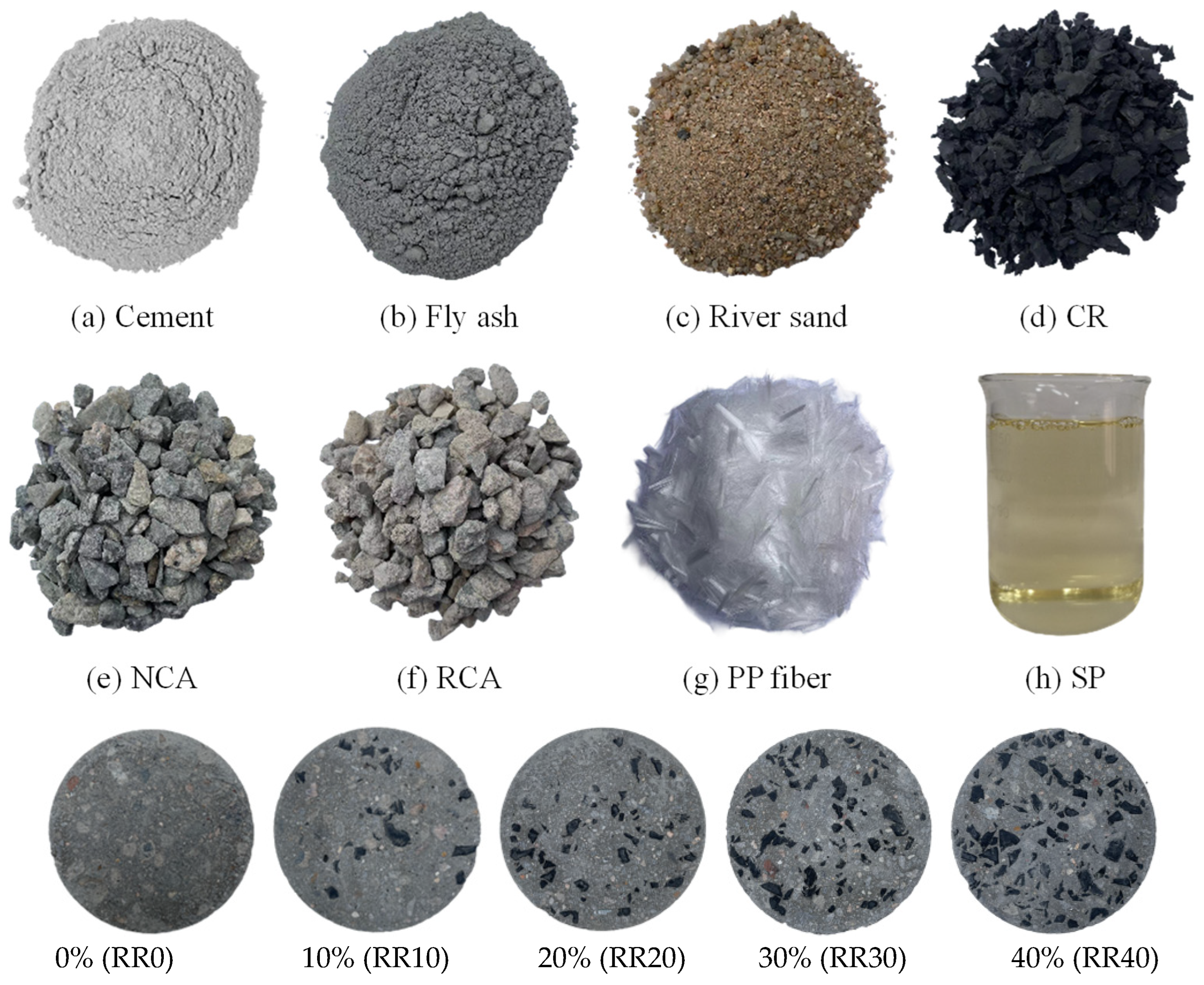
The raw materials used for producing RRAC included PO42.5 Portland cement (RunFeng brand; China Resources Building Materials Technology Holdings Limited, Shenzhen, China), Class F fly ash, river sand, natural coarse aggregate (4.75–19.0 mm), recycled coarse aggregate (4.75–19.0 mm), rubber particles (2.36–19.0 mm), polycarboxylate-based superplasticizer, tap water, and polypropylene fibers. The recycled coarse aggregate was obtained from a local construction waste recycling plant and had a water absorption of approximately 6.8%. Rubber particles were produced by mechanical grinding of end-of-life truck tires, with a density of 1.05 g/cm3 and an average water absorption of 2.5%. Polypropylene fibers had a diameter of approximately 20 μm, a length of 12 mm, and a content of 1.5 kg/m3.
Recycled coarse aggregate fully replaced natural coarse aggregate. Rubber particles were then incorporated by equal-volume substitution of recycled aggregate at five replacement ratios: 0%, 10%, 20%, 30%, and 40% (designated RR0, RR10, RR20, RR30, and RR40, respectively). The water-to-cement ratio was maintained at 0.47 for all mixtures. Specimens were cast in cylindrical molds of Φ100 mm × 50 mm for SHPB testing and standard cube molds for static compressive strength measurement. All specimens were demolded after 24 h and cured in a standard curing room (20 ± 2 °C, relative humidity ≥ 95%) for 28 days. The RRAC specimens are shown in Figure 1 [33].

2.2. Microstructural Characterization by SEM/EDS

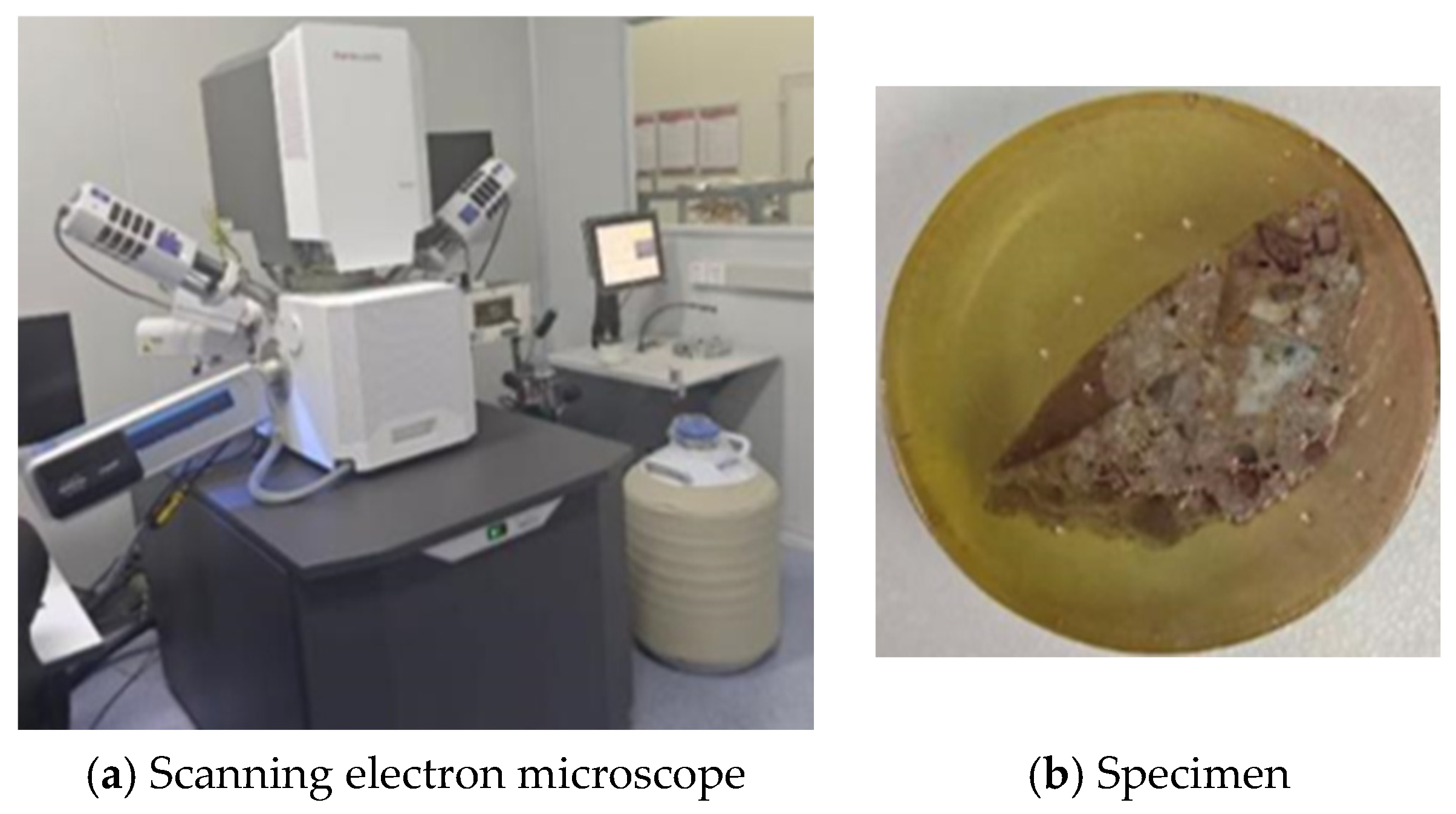
To reveal the microstructural features of RRAC—including the interfacial transition zone, rubber particle dispersion, and the morphology of hydration products—scanning electron microscopy (SEM) coupled with energy-dispersive X-ray spectroscopy (EDS) was performed using a Zeiss Gemini SEM (Zeiss Gemini SEM was manufactured by Carl Zeiss, headquartered in Oberkochen and Jena, in Germany) field emission scanning electron microscope (Figure 2). This combined technique allows for simultaneous high-resolution imaging and elemental microanalysis, which is particularly useful for identifying the chemical composition of cementitious phases and assessing the bonding characteristics between rubber aggregates and the surrounding matrix. For sample preparation, thin slices were extracted from the central region of cured specimens to minimize surface effects and ensure representativeness. These slices were subsequently mechanically ground and polished to a mirror-like finish to eliminate surface scratches, then coated with a thin gold layer via sputter deposition to enhance electrical conductivity and prevent charging effects under electron beam irradiation. All examinations were conducted under high-vacuum conditions at an accelerating voltage of 15 kV, with the working distance and probe current carefully adjusted to obtain optimal image resolution and reliable EDS spectral data.
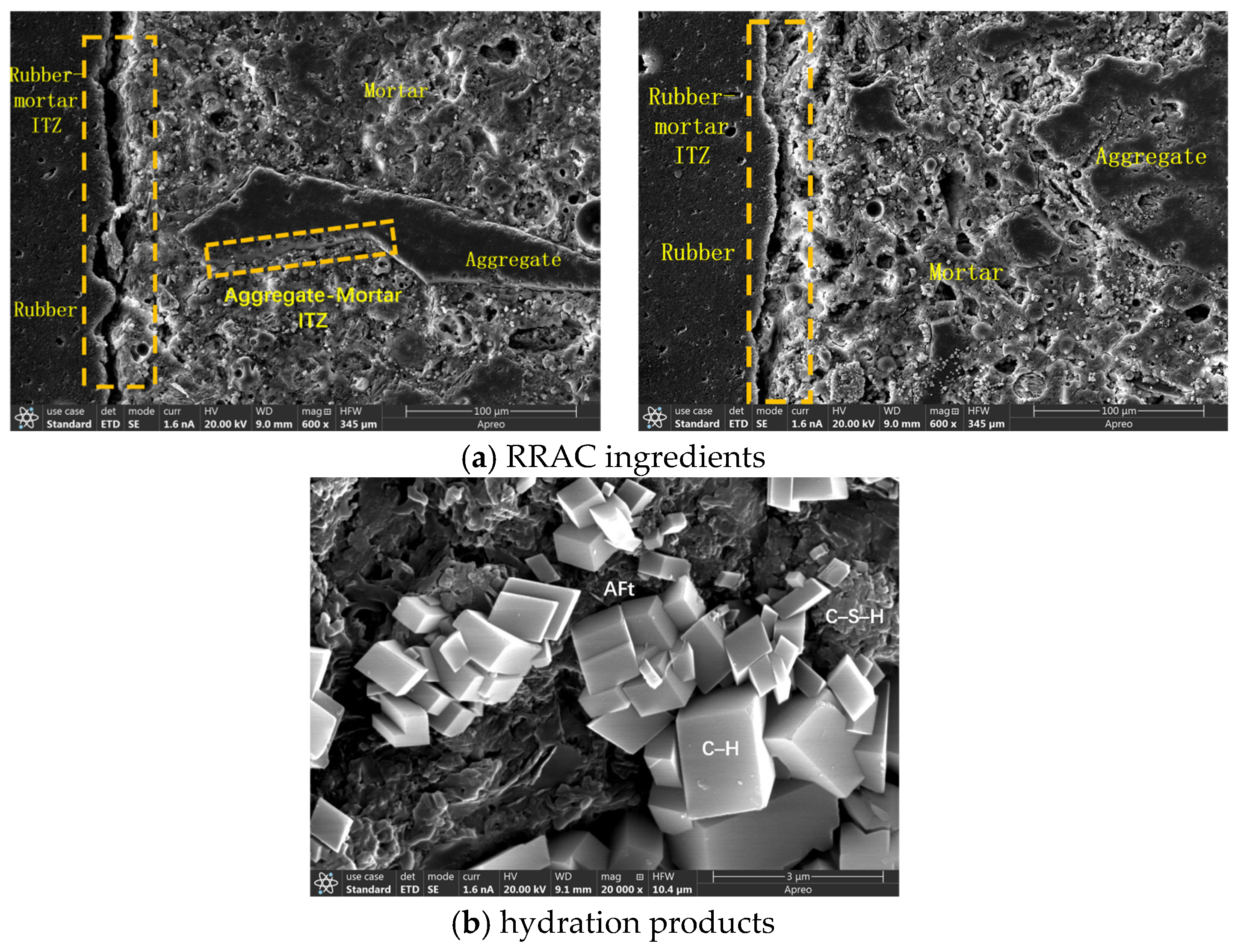
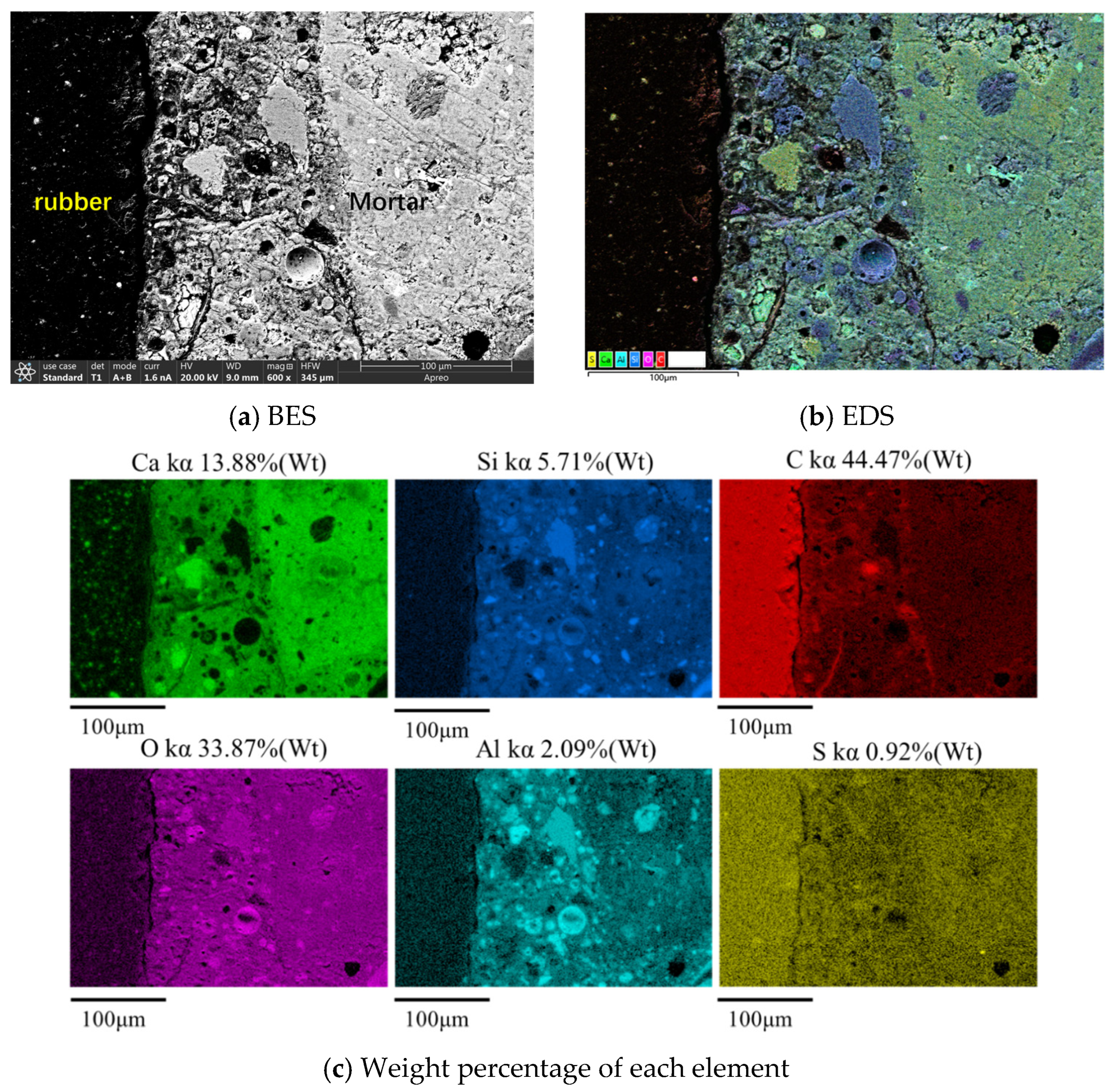
Figure 3 presents a representative SEM image of the RRAC microstructure, showing a rubber particle (appearing as a dark region) embedded within the cementitious matrix. In the vicinity of the rubber–matrix interface, a distinct interfacial transition zone (ITZ) with an average thickness of approximately 20–50 μm was clearly observed. This rubber–matrix ITZ is characterized by the presence of microcracks, noticeably elevated porosity, and a scarcity of hydration products, such as calcium silicate hydrate (C–S–H) and calcium hydroxide (CH). These features arise primarily from the hydrophobic nature of the rubber surface, which inhibits the nucleation and growth of cement hydrates, and from the lack of chemical bonding between the organic rubber and the inorganic cement paste. Unlike the dense, well-crystallized C–S–H layer commonly found around natural aggregates, the rubber surface remains largely bare or is only covered with loosely packed, poorly crystalline phases. Consequently, this weak and porous interface significantly reduces the load-transfer efficiency between the rubber and the matrix. Collectively, these observations confirm that the rubber–matrix ITZ constitutes the weakest phase in RRAC, serving as the preferential site for crack initiation and early propagation under mechanical loading, which in turn governs the material’s overall mechanical performance.
EDS line-scan and mapping analyses across the rubber–matrix interface (Figure 4) reveal a sharp decrease in calcium (Ca) and silicon (Si) signals when moving from the mortar matrix toward the rubber, indicating the virtual absence of C-S-H gel and calcium hydroxide on the rubber surface. The carbon (C) signal peaks at the rubber location, as expected. EDS analysis reveals that the Ca/Si atomic ratio in the mortar matrix is significantly higher than in the interfacial transition zone (ITZ), confirming that the ITZ contains poorly cross-linked C-S-H with weak binding capability. The weak interface is attributed to the hydrophobic nature of rubber, which repels water and raises the local water-to-cement ratio, combined with the smooth rubber surface that offers no mechanical interlocking and inhibits nucleation of hydration products. Consequently, even after 28 days of standard curing, the ITZ remains porous and poorly bonded. These microstructural observations directly inform the mesoscale model developed in Section 3, where the rubber–matrix ITZ is explicitly represented as a distinct phase with substantially reduced mechanical properties.

2.3. SHPB Dynamic Compression Test

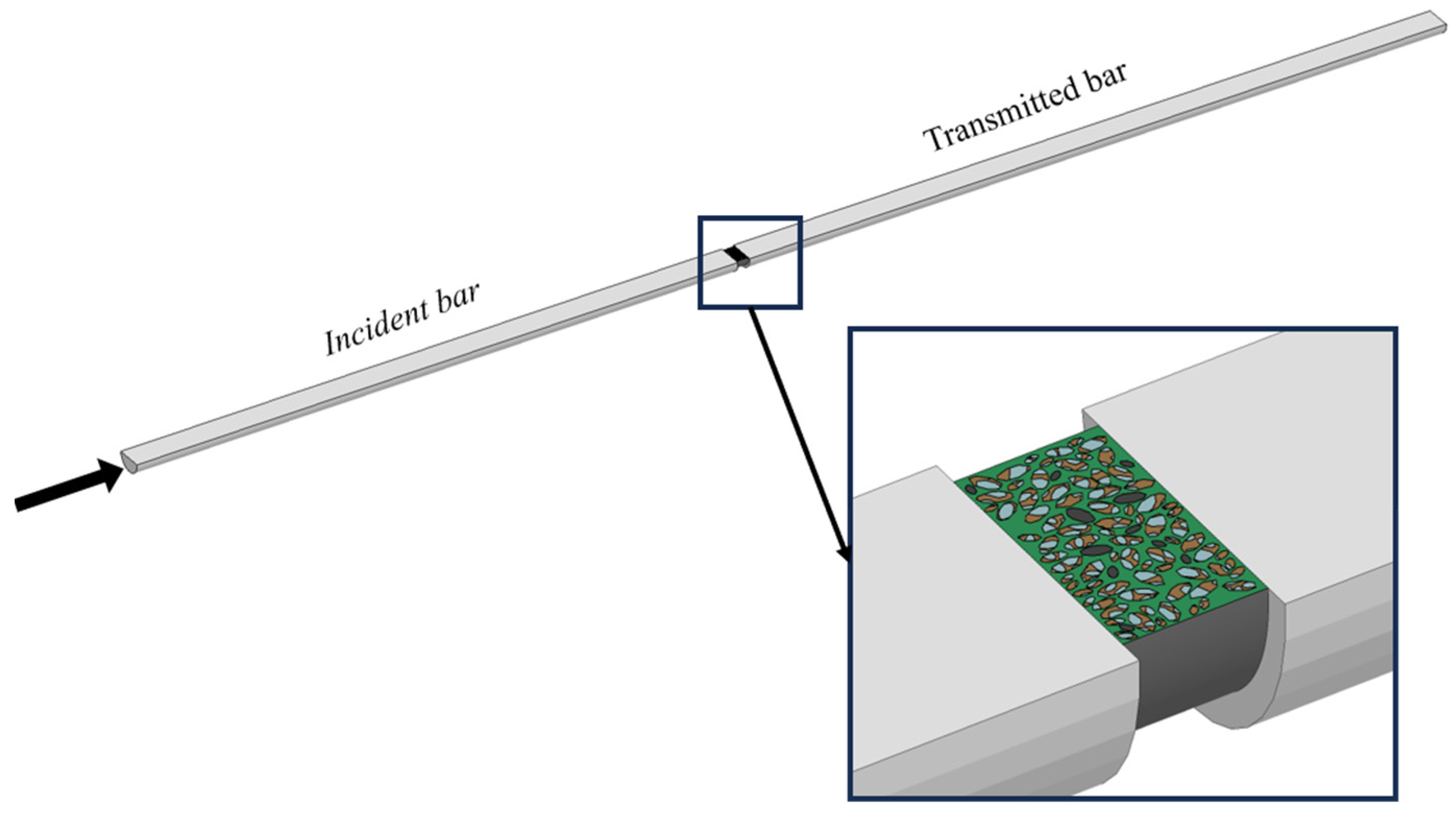
Dynamic compression tests were conducted using a split Hopkinson pressure bar (SHPB) system with a bar diameter of 120 mm, as shown in Figure 5 [33]. The lengths of the striker bar, incident bar, and transmission bar were 800 mm, 6000 mm, and 4000 mm, respectively. The bars were made of high-strength steel with a density of 7850 kg/m3, an elastic modulus of 206 GPa, and a longitudinal wave velocity of 5100 m/s. The specimens were Φ100 mm × 50 mm cylinders, which satisfied the slenderness requirement for SHPB testing of concrete-like materials. The specimen was sandwiched between the incident and transmission bars. A striker bar launched by compressed gas impacted the free end of the incident bar, generating a compressive stress pulse. Strain gauges mounted on the incident and transmission bars recorded the incident strain εi(t), reflected strain εr(t), and transmitted strain εt(t).
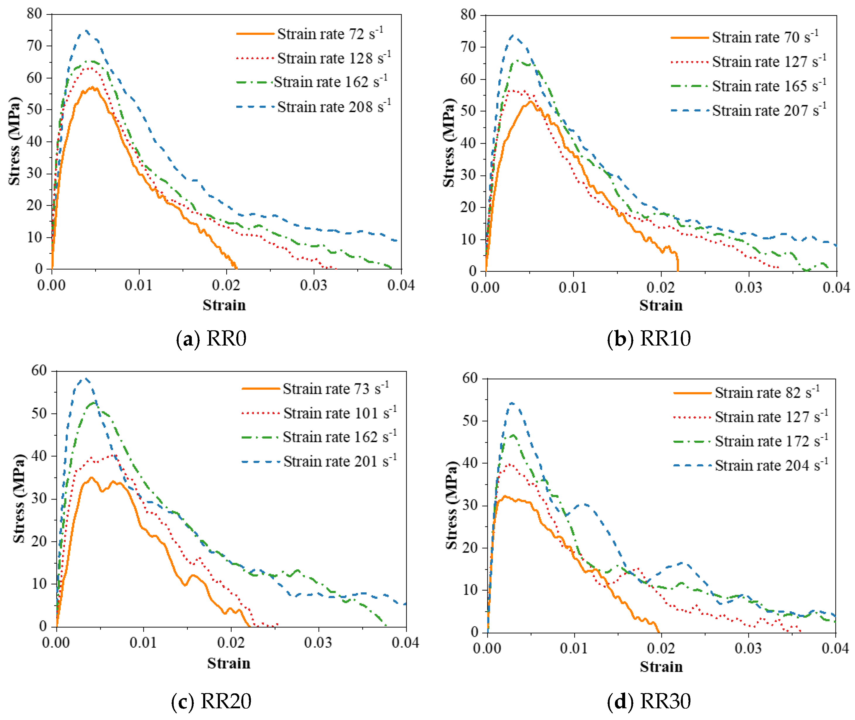
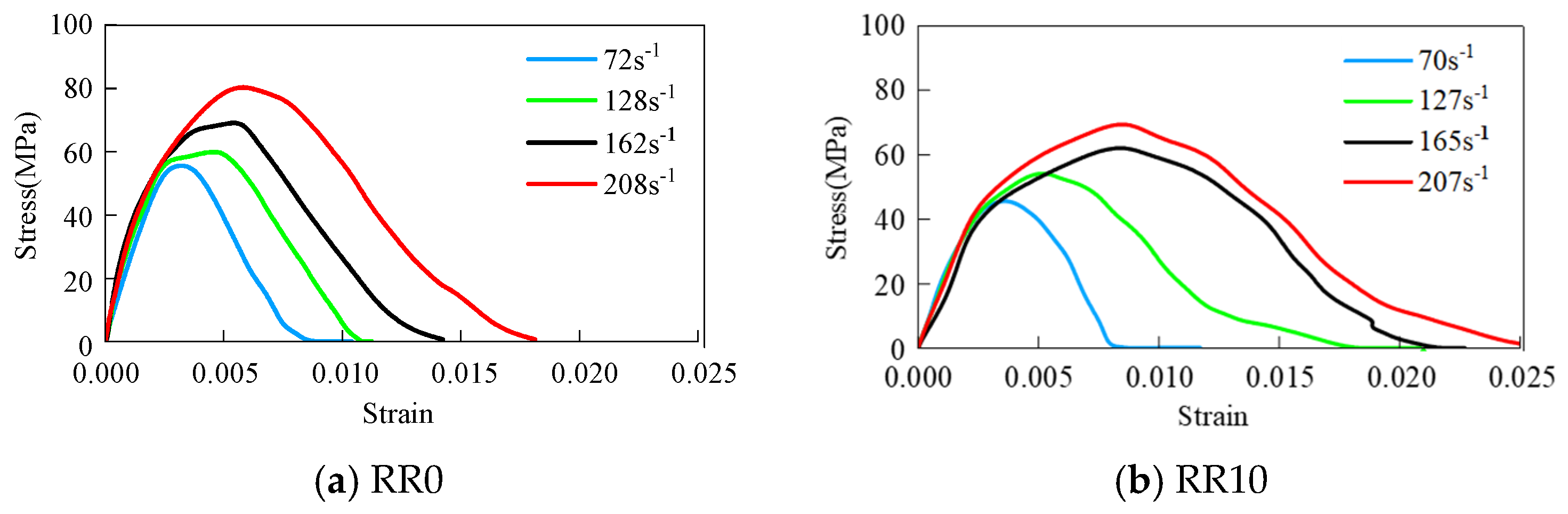
Tests were performed at four nominal strain rate levels: approximately 70, 120, 160, and 200 s−1 (exact values varied slightly for different cases). It is worth noting that the strain rate in a SHPB test is not constant; an average strain rate over a certain time range is used as the nominal strain rate. At least three specimens were tested for each mixture and each strain rate. Figure 6 shows typical dynamic stress–strain curves for RRAC with different rubber contents at different strain rates from about 70 to 208 s−1 [33]. All curves exhibit a linear elastic initial stage, followed by a nonlinear hardening stage up to the peak stress, and then a descending softening stage. The peak stress decreases progressively with increasing rubber content. For RR0, the peak stress is 61.6 MPa at a strain rate of 128 s−1; whereas for RR40, this value drops to 35.9 MPa, representing a reduction of approximately 42%. However, the post-peak descending branch becomes noticeably more gradual with increasing rubber content, indicating enhanced ductility and energy dissipation capacity.
Toughness index, defined as the ratio of the area under the descending branch (up to 30% of the peak stress) to the area under the ascending branch, was calculated for the specimens. At a strain rate of 127 s−1, the toughness indices for RR10 and RR30 were 2.665 and 4.128, respectively, compared with 1.803 for RR0. This shows that rubber incorporation substantially improves the post-peak energy absorption and deformability of the material, demonstrating enhanced post-peak energy absorption with rubber incorporation.

3. Pseudo-3D Mesoscale Model Development and Validation

3.1. Seven-Phase Model Construction

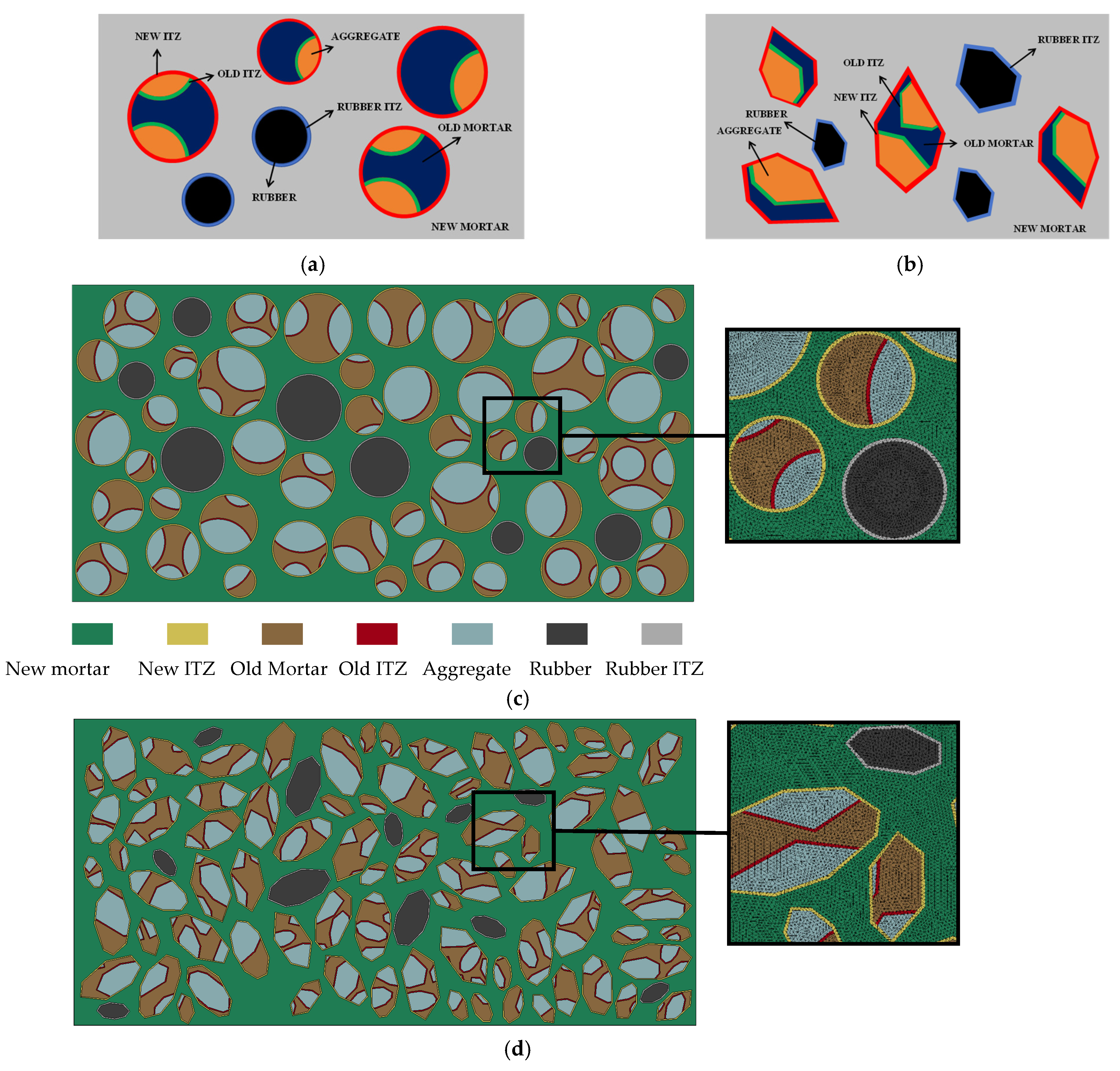
Based on SEM/EDS observations, a pseudo-3D seven-phase mesoscale model was developed, incorporating natural aggregate, old mortar, old ITZ, new mortar, new ITZ, rubber particles, and rubber–matrix ITZ. The model geometry corresponds to the experimental Φ100 mm × 50 mm cylindrical specimen.
To balance computational accuracy and efficiency, the thickness of all ITZs (old ITZ, new ITZ, and rubber ITZ) was uniformly set to 0.2 mm. It should be noted that this value exceeds the experimentally observed ITZ thickness, which was too small to be resolved within the numerical discretization. This simplification is justified on two grounds. First, from a homogenization perspective, the ITZ is treated as an equivalent interfacial zone that captures the average reduction in material properties rather than the exact geometric dimension. Second, the adopted thickness represents the minimum value that ensures mesh quality and numerical convergence without incurring excessive computational cost. Moreover, a preliminary sensitivity analysis confirmed that varying the ITZ thickness within a reasonable range does not qualitatively alter the predicted macroscopic behavior, indicating that the model is robust to this geometric idealization.
A normal concrete model was first generated. Circular and polygonal aggregates were produced based on the experimental gradation (4.75–19.0 mm), using a random placement algorithm with interference detection. For polygonal aggregates, ellipses were first randomly generated and then converted into polygons by inscribing points along the ellipse periphery, thereby better representing the rough contours and angular features of real aggregates.
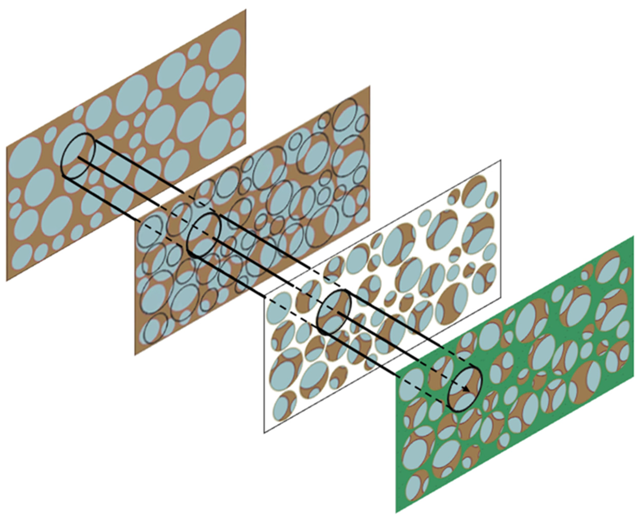
A two-step approach was adopted to generate the recycled aggregate (Figure 7). First, an “old concrete” mesoscale model was constructed, comprising natural aggregate, old ITZ, and old mortar. Subsequently, recycled aggregate particles—each consisting of natural aggregate with attached old mortar and old ITZ—were extracted with realistic morphology and re-embedded into the new mortar matrix, with a new ITZ introduced between the recycled aggregate and the new mortar.
Rubber particles were randomly dispersed into the matrix at volume substitution rates of 0%, 10%, 20%, 30%, and 40% (corresponding to RR0, RR10, RR20, RR30, and RR40, respectively), substituting an equal volume of recycled aggregate. The random placement algorithm incorporated collision detection to prevent overlapping with existing aggregates and boundary walls. Typical resulting 2D mesoscale models of RRAC are illustrated in Figure 8.
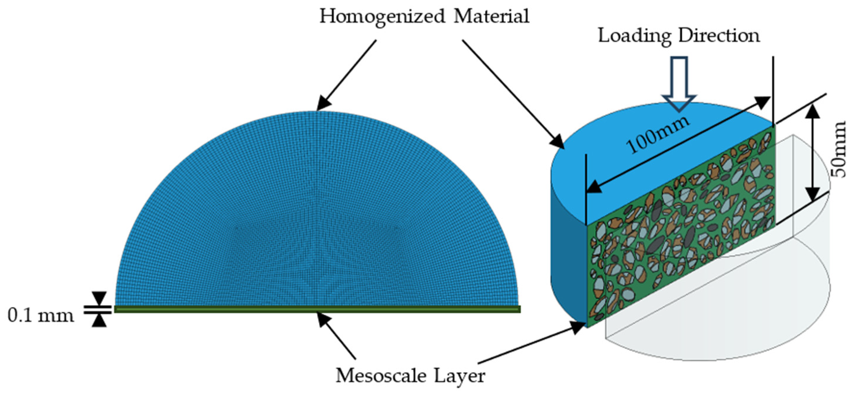
To capture 3D confinement effects—specifically the lateral inertial confinement induced by dynamic compression—while maintaining computational efficiency, a pseudo-3D approach [46] was adopted. In this configuration, a 0.1 mm-thick 2D mesoscale slice is sandwiched between two homogeneous half-cylinders. Benefiting from symmetry, the simulation can be simplified to include only the central mesoscale slice and one homogeneous half-cylinder (Figure 9).

3.2. Material Constitutive Models

The K&C dynamic constitutive model [44] was employed for the natural aggregate, old mortar, new mortar, and all interfacial transition zones (ITZs). The entire loading process up to concrete failure can be divided into three main phases: (i) the elastic stage, where the stress state remains below the initial yield surface; (ii) the strengthening stage, during which the stress exceeds the initial yield surface but has not yet reached the ultimate strength surface; and (iii) the softening stage, characterized by the stress reaching the ultimate strength surface but still staying below the residual failure surface. The initial yield, ultimate strength, and residual failure surfaces are given by Equations (1), (2), and (3), respectively.
Δ σ y = a 0 y + P a 1 y + a 2 y P
Δ σ m = a 0 + P a 1 + a 2 P
Δ σ r = P a 1 f + a 2 f P
where P = ( σ 1 + σ 2 + σ 3 ) / 3 and a 0 , a 1 , a 2 , a 0 y , a 1 y , a 2 y , a 1 f , and a 2 f are the material parameters.
Material parameters were determined based on compressive strength. Given the fine dimensions and widespread distribution of the fibers, explicit modeling at the mesoscale would entail significant computational costs; therefore, the influence of the polypropylene fibers was incorporated into the mechanical parameters of the mortar matrix using a macroscopic equivalent approach, rather than by creating independent fiber models. The parameters for the new mortar material—which effectively represent the fiber-reinforced mortar—were determined based on experimental data, yielding an average compressive strength of 27.92 MPa. Based on previous research [42,47], the compressive strength of old mortar was set to 92% of that of new mortar (25.69 MPa). The compressive strengths of the new and old ITZs were both taken as 65% of their respective mortar strengths, while the rubber ITZ strength was assigned as 35% of the new mortar strength [48]. The main material parameters for aggregates, new mortar, old mortar, and all ITZs were determined and are summarized in Table 1. Strain-rate effects were accounted for using the compressive dynamic increase factor (CDIF) proposed by Li and Meng [49].
C D I F = 1 + ( log ( ε ˙ d ) + 3 ) × 0.03438 β 0 + β 1 log ( ε ˙ d ) + β 2 log 2 ( ε ˙ d )               ε ˙ d 1 0 2 s 1           ε ˙ d > 1 0 2 s 1
where DIF = fcd/fcs is the dynamic increase factor, fcd is the dynamic compressive strength and fcs is the static compressive strength; ε ˙ d represents the dynamic strain rate; and β0 = 8.5303, β1 = −7.1372, and β2 = 1.729.
Rubber-like materials have strongly nonlinear stress–strain behavior and can undergo large strains, so linear elastic models are not suitable. The Mooney–Rivlin model [45] uses a strain energy density function W to describe the stress–strain relation. Its general form involves material constants Cij, dk and strain invariants I1, I2, I3. The most common version is the two-parameter form:
W = C 10 I 1 3 + C 01 I 2 3 + 1 d J 1 2
where C10 = 0.58643, C01 = −3.8942 × 10⁻², and Poisson’s ratio = 0.499. The rubber is treated as nearly incompressible, so J = 1.

3.3. SHPB Model and Simplification

To accurately reproduce the SHPB test results numerically, a full-scale finite element model of the experimental system was first established, incorporating the incident bar, transmitted bar, and concrete specimen, with its geometric configuration shown in Figure 10. The same stress wave applied in the experiment was imposed on the incident bar end to achieve an equivalent strain rate during impact simulation. The model comprises a total of 914,824 solid elements, demanding substantial time and computational resources for both preprocessing and solutions.
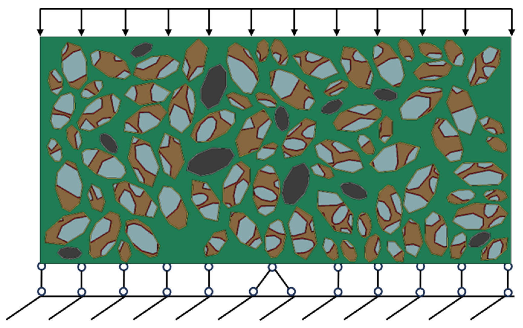
To improve computational efficiency, a simplified model was adopted in which the incident and transmission bars were omitted. The simplified boundary conditions are illustrated in Figure 11. A velocity load v was applied at the loading end, while a fixed boundary condition was imposed at the constrained end.
v = t t 0 v 0   f o r   t     t 0 ;   v = v 0   f o r   t     t 0
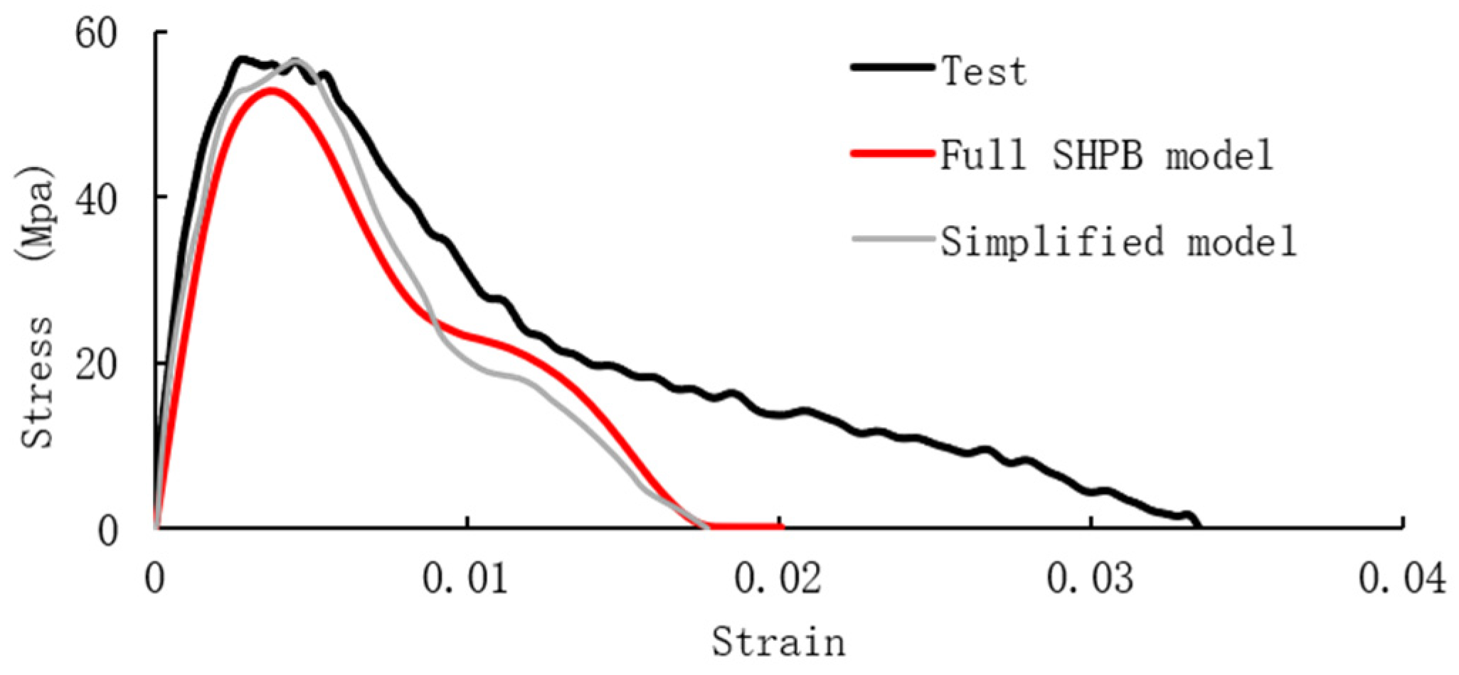
where t0 = n·2L/c (L: specimen height, c: elastic wave speed in specimen, n = 3 or 4 [50]). Comparison between the full SHPB model and simplified model shows good agreement in compressive strength and overall mechanical response, validating the simplified approach for parametric analysis (Figure 12). Therefore, considering both computational efficiency and acceptable accuracy of key parameters, a simplified specimen model with only velocity boundaries applied is chosen for the present study to perform parametric analysis in subsequent simulations.

3.4. Comparison with Homogeneous Model

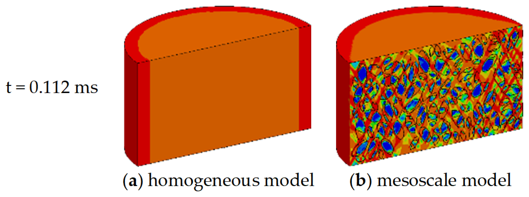
The effectiveness of the pseudo-3D configuration in reproducing a 3D stress state was first verified by comparing its damage contours with those obtained from a fully 3D homogeneous model. Figure 13 presents a damage comparison within the mesoscale plane between the pseudo-3D model and its 3D homogeneous counterpart. Under identical loading conditions, both models exhibit similar overall damage distribution trends; however, the pseudo-3D mesoscale model distinctly captures the processes of crack initiation and propagation. In contrast, the homogeneous model, constrained by its assumption of material uniformity, fails to represent discontinuous damage behavior, fragment distribution, or localized failure morphology. Overall, the pseudo-3D mesoscale model demonstrates superior capability in characterizing damage evolution and fragmentation behavior, while maintaining reasonable computational cost.

4. Results

This section presents the simulation results of the pseudo-3D seven-phase model. The dynamic damage evolution and failure morphology are first examined, followed by a quantitative analysis of stress–strain responses and compressive strength. Subsequently, the effects of aggregate shape and strain rate are systematically evaluated.

4.1. Dynamic Compressive Damage Development and Final Failure Morphology

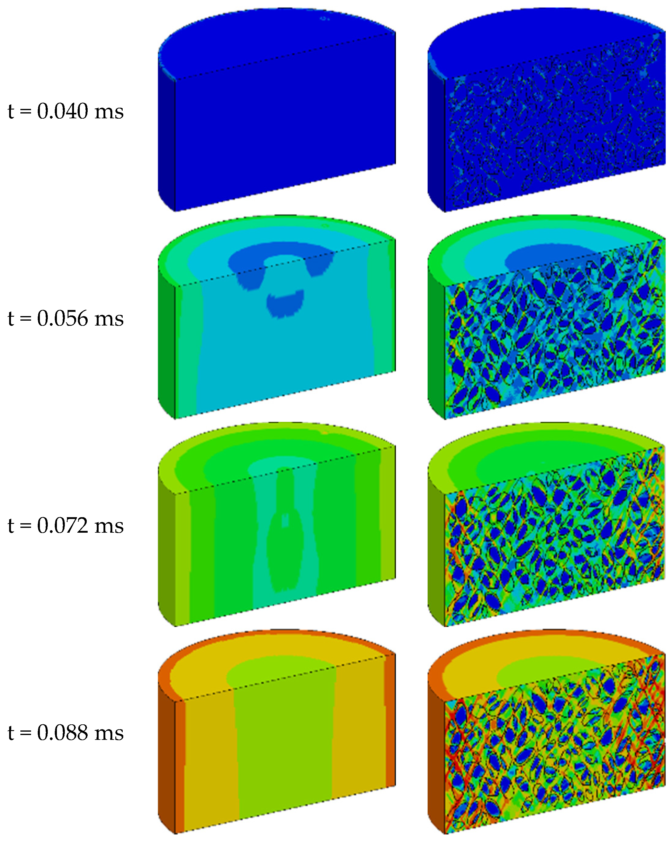
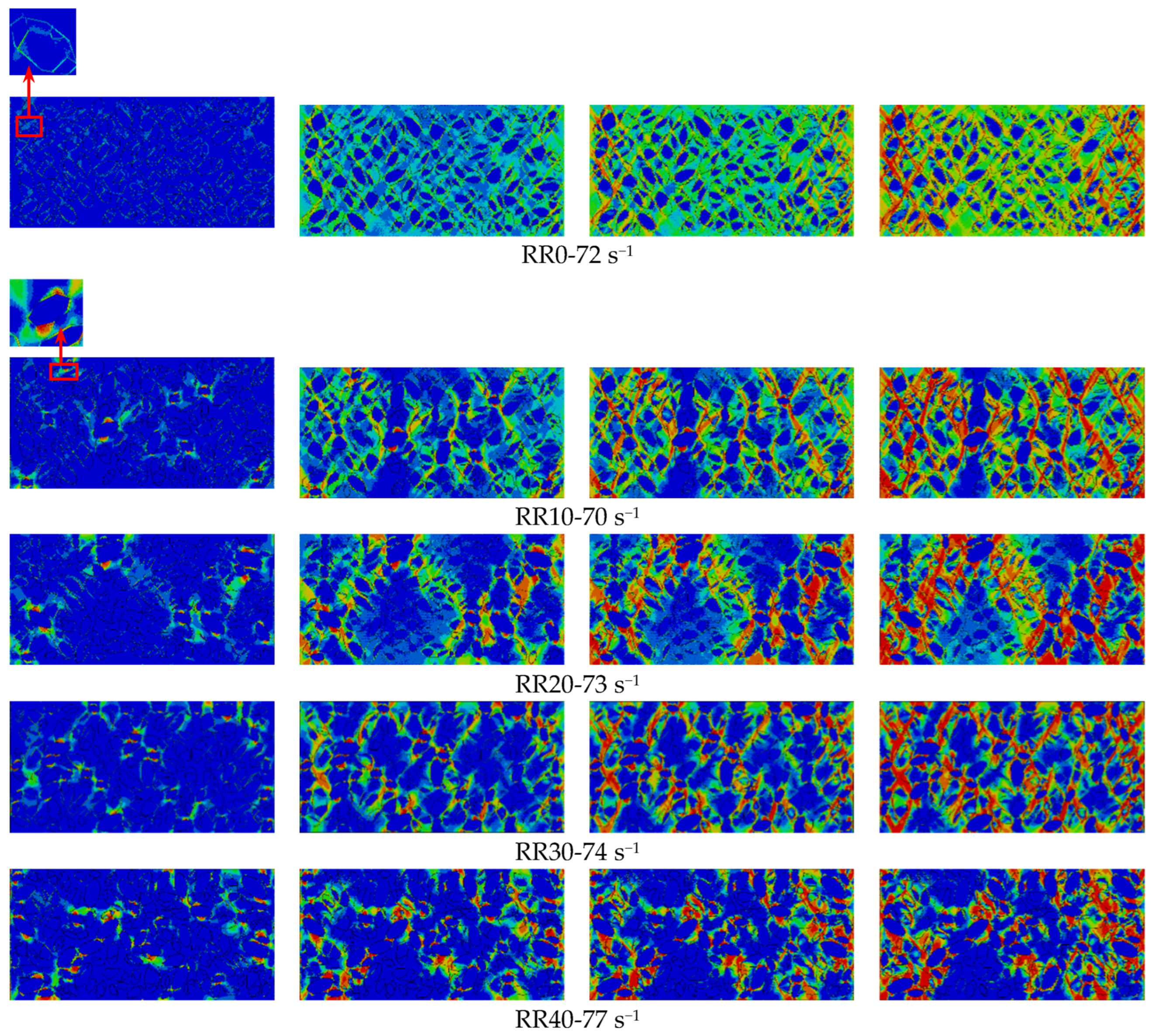
Figure 14 presents the damage evolution of polygonal aggregate RRAC models subjected to dynamic compression at different strain rates. For RR0, damage initiates at the old ITZ, with microcracks subsequently propagating through the old mortar, crossing the new ITZ, and extending into the new mortar to form interconnected major cracks. Damage generally originates at the specimen surface and moves inward, since the interior concrete remains under triaxial compression from lateral confinement, delaying failure.
With rubber added, the failure mode shifts notably. Damage starts at the rubber ITZ and spreads to neighboring rubber ITZ or new ITZs around recycled aggregate.
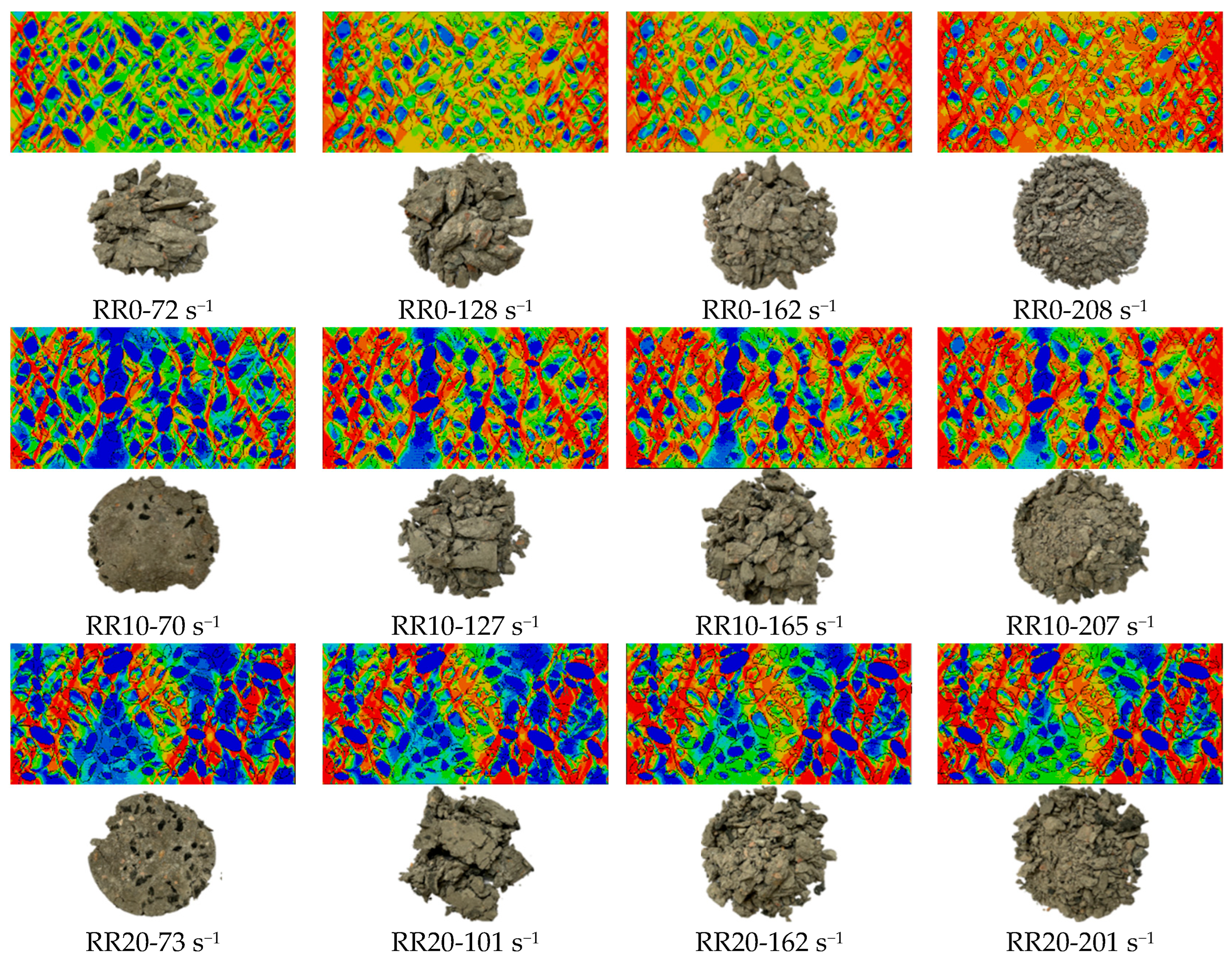
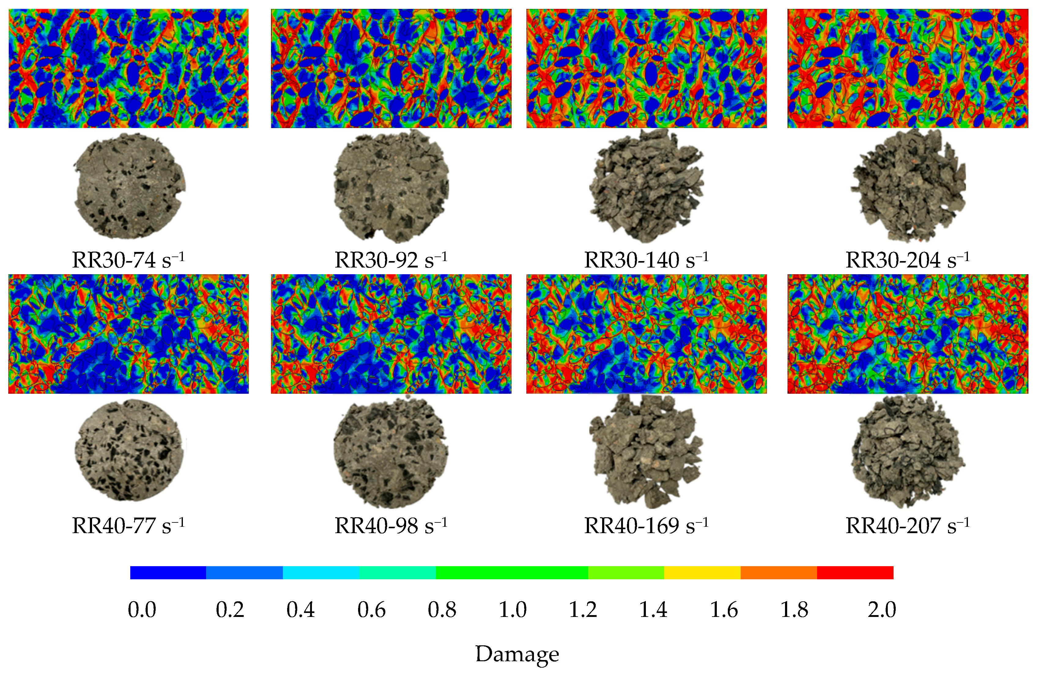
Figure 15 presents a comparison of final failure morphologies between models with varying rubber contents and experimental observations. For all specimens, the degree of damage increases substantially with rising strain rate. At a low strain rate of ~72 s−1, the RR0 specimen exhibits only a limited number of fine cracks and retains relatively large fragments. As the strain rate is elevated to 128 s−1 and subsequently to 208 s−1, the crack density increases sharply and fragment sizes diminish progressively; at 208 s−1, the specimen is reduced to an almost fully pulverized state.
The introduction of rubber significantly modifies crack propagation paths and spatial distribution patterns. At equivalent strain rates, rubber-containing specimens consistently display more intact final morphologies or coarser fragments compared to the rubber-free control. For example, within the strain rate range of ~70–100 s−1, RR0 specimens are pervasively cracked, whereas RR30 and RR40 specimens exhibit only minor cracking. This beneficial effect stems from the rubber particles’ capacity to dissipate a substantial portion of impact energy through large elastic deformation and stress relaxation, which not only hinders the initiation of extensive matrix cracking but also redirects crack propagation preferentially along interfacial zones, thereby preventing catastrophic pulverization.

4.2. Dynamic Compressive Stress–Strain Curves and Dynamic Compressive Strength

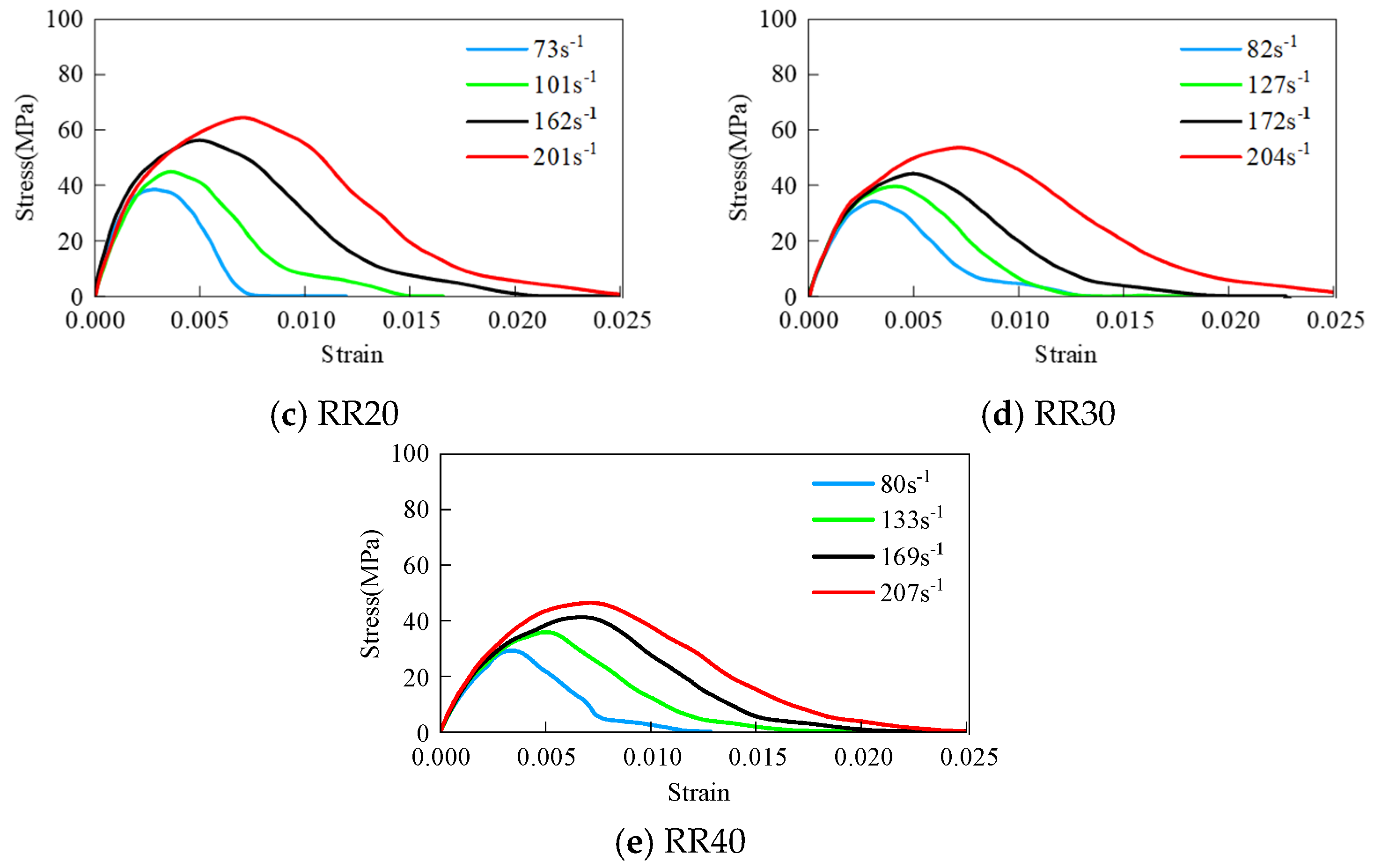
Figure 16 presents the stress–strain curves for specimens with varying rubber contents at comparable strain rates (~70–200 s−1). As the rubber content increases, the peak stress gradually decreases, whereas the corresponding ultimate strain increases, and the overall curve becomes more gradual. In the linear elastic region, the slope (tangent modulus) of RRAC is lower than that of plain RAC and continues to decrease with increasing rubber replacement ratio, indicating that rubber incorporation reduces stiffness while enhancing toughness. In the nonlinear ascending stage, the peak stress decreases with increasing rubber content. In the post-peak descending stage, rubber incorporation delays the failure process to a certain extent, reflecting its moderating effect on failure morphology.
The dynamic compressive strength is defined as the maximum compressive stress reached by the specimen under dynamic loading, corresponding to the peak stress on the dynamic stress–strain curve. Table 2 summarizes the dynamic compressive strengths of polygonal aggregate models with varying rubber contents at different strain rates. The results indicate that, at all strain rate levels, the ultimate compressive strength decreases progressively with increasing rubber content. For instance, at strain rates of ~70–80 s−1, RR0 attains 55.1 MPa, whereas RR40 reaches only 29.3 MPa, corresponding to a 47% reduction. This strength degradation is consistent with the presence of weaker rubber ITZ and the low-modulus rubber particles acting as “soft inclusions” within the cementitious matrix.
Meanwhile, the dynamic compressive strength exhibits considerable rate sensitivity. For RR20, the strength increases from 38.5 MPa at 73 s−1 to 60.1 MPa at 201 s−1, representing a 56% enhancement. This strain-rate strengthening effect is attributable to the limited time available for crack propagation under high strain rates, which forces the impact load to be transmitted primarily through the stronger coarse aggregate skeleton.

4.3. Effect of Aggregate Shape

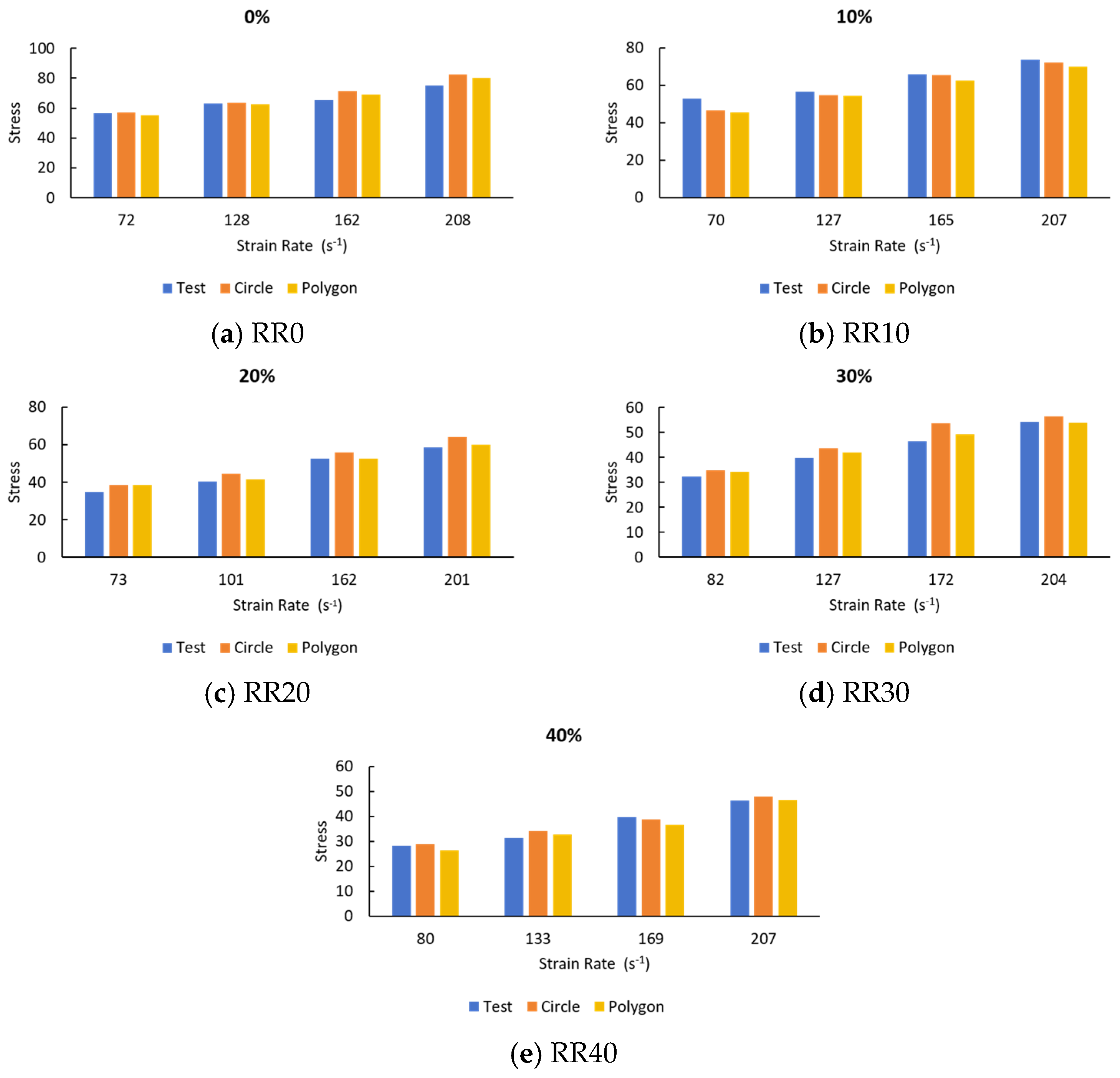
As shown in Figure 17, the comparison between polygonal and circular aggregate models reveals that specimens with polygonal aggregates exhibit slightly higher levels of internal damage under dynamic loading. This observation can be attributed to the sharp corners and angular edges of polygonal particles, which tend to induce localized stress concentrations and promote the initiation and coalescence of microcracks within the cementitious matrix. Consequently, the fracture toughness of the polygonal-aggregate concrete appears to be somewhat inferior, as the irregular geometry facilitates crack propagation along the aggregate–matrix interface. In contrast, circular aggregate specimens, owing to their smoother contours and more uniform stress distribution, experience reduced stress concentration effects. This results in marginally higher compressive strength and elastic modulus—approximately 2–5% greater than those of their polygonal counterparts. Nevertheless, when it comes to dynamic compressive strength specifically, the differences between the two aggregate shapes are remarkably small, falling within the range of experimental scatter. This finding suggests that, within the parameter space investigated in this study, aggregate shape plays only a secondary role in governing the macroscopic mechanical response of RRAC. Rather, the dominant factors are the rubber content and the applied strain rate, both of which exert a far more pronounced influence on the material’s strength and deformation behavior under high-rate loading conditions.

4.4. Strain Rate Effect and DIF

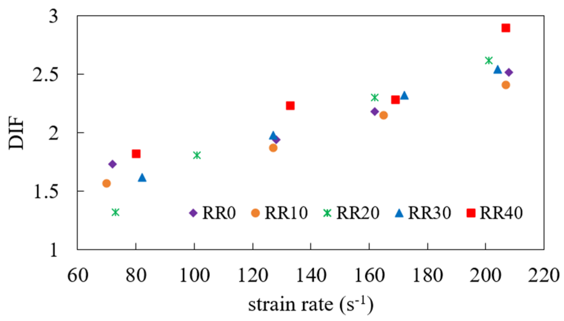
The DIF, dynamic increase factor, defined as the ratio of dynamic compressive strength to static reference strength, was calculated to quantify strain rate sensitivity. The static reference strengths were obtained from the experimental results [33]. Figure 18 shows the DIF versus strain rate for different rubber contents. Except for RR10, rubber incorporation slightly increases DIF at high strain rates. RR30 and RR20 show similar DIF values, while RR40 exhibits a modest increase in DIF at high strain rates. This indicates that higher rubber content enhances the material’s strain rate sensitivity.
The dynamic strengthening effect can be explained by the mesoscale crack-arrest mechanism. Under high strain rate loading, propagating cracks encounter rubber particles, which undergo large nonlinear deformation and redistribute local stress concentrations, thereby delaying crack propagation. At lower loading rates, crack propagation synchronizes with external stress increase; however, as strain rate increases, crack development lags behind stress rise, contributing to higher apparent compressive strength under dynamic loading. After failure, rubber particles further inhibit the coalescence of macroscopic cracks, and their high deformability helps redistribute and alleviate local stress concentrations around pores, thereby limiting microcrack initiation and propagation.

5. Discussion

5.1. Role of the Rubber–Matrix ITZ in Damage Initiation

The numerical results indicate that the rubber–matrix ITZ is the preferential location for damage initiation in rubber-containing RRAC. This finding is consistent with the SEM observations, which show a relatively porous interfacial region characterized by microcracks and a lower concentration of hydration products around the rubber particles. The experimentally observed rubber–matrix ITZ thickness was approximately 20–50 μm, and the EDS results further indicated a reduction in calcium and silicon signals near the rubber surface. These microstructural characteristics support the representation of the rubber–matrix ITZ as a distinct weak phase in the mesoscale model.
Mechanically, the preferential damage initiation can be attributed to the substantial mismatch in stiffness and transverse deformation characteristics between rubber and the surrounding cementitious matrix. Under dynamic compression, this mismatch produces localized interfacial stress concentrations and promotes tensile and shear stresses around the rubber particles. Once local damage develops, cracks can propagate from the rubber–matrix ITZ toward neighboring ITZs and mortar regions.

5.2. Strength–Deformability Trade-Off Induced by Rubber

The results demonstrate a clear trade-off between compressive strength and deformability. Increasing rubber content decreases the dynamic compressive strength because rubber particles have a much lower stiffness than the cementitious matrix and introduce relatively weak interfaces. However, the reduction in strength is accompanied by a more gradual post-peak response and less catastrophic fragmentation.
This behavior is consistent with previous experimental observations of rubberized and rubberized recycled concrete, which generally report lower compressive strength but improved ductility, energy absorption, and impact resistance. The present study extends these observations by identifying the mesoscale mechanism responsible for this macroscopic trade-off. Rather than increasing the intrinsic strength of RRAC, rubber particles modify the crack propagation process by providing highly deformable inclusions and additional interfacial regions.

5.3. Strain-Rate Dependence

Both the experimental results and numerical simulations indicate substantial strain-rate strengthening. For example, the simulated compressive strength of RR20 increases by approximately 56% as the strain rate increases from 73 to 201 s−1. At higher loading rates, the time available for stable crack growth is reduced, and the rapid stress increase limits the development and coalescence of cracks. Consequently, a greater proportion of the applied load is carried by the relatively stiff aggregate–mortar skeleton before extensive damage develops.
Rubber particles further modify this process by interrupting crack propagation and accommodating local deformation. However, the present results suggest that the influence of rubber content on DIF is not strictly monotonic for every replacement ratio. Therefore, the strain-rate sensitivity should be interpreted as a coupled effect of rubber content, interfacial properties, and dynamic crack evolution rather than as a simple linear function of rubber replacement.

5.4. Contribution of Aggregate Shape

Aggregate shape has a noticeably smaller influence than rubber content and strain rate within the parameter range investigated. Polygonal particles produce more localized stress concentrations near sharp corners, whereas circular particles generate smoother stress distributions. Nevertheless, the resulting difference in dynamic compressive strength is generally below 5%.
This result indicates that, for the present dynamic compression conditions, the mechanical contrast between rubber, ITZs, and cementitious phases plays a substantially greater role than the geometric difference between circular and polygonal aggregate representations.

5.5. Originality and Engineering Implications

The principal contribution of the present study is the development of a pseudo-3D seven-phase mesoscale representation specifically for RRAC. Previous mesoscale studies have primarily focused on conventional concrete or RAC, while rubberized concrete models have often adopted simplified phase representations or focused on static fracture behavior. The present model explicitly distinguishes natural aggregate, old mortar, new mortar, old ITZ, new ITZ, rubber particles, and rubber–matrix ITZ, thereby enabling the evolution of damage at the critical rubber–matrix interface to be directly examined.
The pseudo-3D configuration also provides a computationally efficient compromise between a fully three-dimensional heterogeneous model and a conventional two-dimensional mesoscale model. The comparison with the homogeneous 3D model demonstrates that the pseudo-3D mesoscale representation can capture localized crack initiation, propagation, and fragmentation while maintaining reasonable computational efficiency.
From an engineering perspective, the results suggest that RRAC may be particularly attractive for components in which deformation capacity, energy absorption, and resistance to catastrophic fragmentation are important. Potential applications include roadside barriers, bridge parapets, protective walls, and other transportation or protective infrastructure. However, the present findings should not be interpreted as indicating that high rubber-content RRAC should universally replace conventional high-strength concrete in primary load-bearing members. Rather, its potential advantage lies in applications where controlled deformation and energy dissipation are important design objectives.

6. Conclusions

Based on experimental characterization and pseudo-3D seven-phase mesoscale simulations, the following conclusions can be drawn:
(1)
Mesoscale model development.
A pseudo-3D seven-phase mesoscale finite element model was developed for RRAC based on SEM/EDS observations. The model explicitly represents natural aggregates, old mortar, new mortar, old ITZs, new ITZs, rubber particles, and the rubber–matrix ITZ. The model successfully reproduces the principal features of the experimentally observed dynamic stress–strain response and failure morphology.
(2)
Damage initiation and propagation mechanism.
The rubber–matrix ITZ is identified as the preferential location for damage initiation in rubber-containing RRAC. The substantial mismatch in stiffness and transverse deformation between rubber and the surrounding cementitious matrix produces localized interfacial stresses under dynamic compression. Damage subsequently propagates from the rubber–matrix ITZ toward adjacent ITZs and mortar regions.
(3)
Effect of rubber content.
Increasing rubber content progressively reduces dynamic compressive strength because rubber particles act as relatively soft inclusions and introduce weak interfacial regions. At approximately 70–80 s−1, the simulated strength decreases from 55.1 MPa for RR0 to 29.3 MPa for RR40, corresponding to a reduction of approximately 47%. In contrast, rubber incorporation increases deformation capacity and improves resistance to catastrophic fragmentation.
(4)
Strain-rate effect.
RRAC exhibits pronounced strain-rate strengthening. For RR20, the dynamic compressive strength increases from 38.5 MPa at 73 s−1 to 60.1 MPa at 201 s−1, corresponding to an increase of approximately 56%. The strengthening effect is attributed primarily to the limited time available for crack initiation, propagation, and coalescence under high-rate loading.
(5)
Effect of aggregate shape.
Polygonal aggregates produce somewhat stronger local stress concentrations and more localized damage than circular aggregates. Nevertheless, the difference in dynamic compressive strength between the two aggregate representations remains generally below 5%, indicating that aggregate shape has only a secondary influence compared with rubber content and strain rate within the investigated parameter range.
(6)
Engineering implications.
The results demonstrate that RRAC possesses a useful combination of sustainability, deformability, and impact-energy dissipation, despite the reduction in compressive strength associated with rubber incorporation. Therefore, RRAC may have potential applications in roadside barriers, bridge parapets, protective walls, and other transportation or protective infrastructure where energy absorption and resistance to catastrophic fragmentation are important. However, the present results should not be interpreted as evidence that high-rubber-content RRAC is universally suitable for replacing conventional high-strength concrete in primary load-bearing members. Further full-scale experimental investigations are required before practical structural implementation.
Future work could extend the present model to mixed-mode or multi-axial dynamic loading, or develop a full 3D mesoscale model to better capture spatial damage evolution and confinement effects.

Author Contributions

Conceptualization, X.Z.; methodology, X.Z. and L.J.; software, L.J. and H.Z.; validation, X.Z. and H.Z.; formal analysis, W.L.; investigation, W.L.; writing—original draft preparation, X.Z. and H.Z.; writing—review and editing, X.Z.; supervision, X.Z.; funding acquisition, X.Z. All authors have read and agreed to the published version of the manuscript.

Funding

This research was funded by the Natural Science Foundation of Guangdong Province, China. (Grant No. 2025A1515011697).

Data Availability Statement

The original contributions presented in this study are included in the article. Further inquiries can be directed to the corresponding author.

Acknowledgments

The authors gratefully acknowledge Zhenlin Peng from Shenzhen Senior High School for his valuable contributions to this study, particularly to the development of the mesoscale model and part of the data processing. His assistance is sincerely appreciated.

Conflicts of Interest

The authors declare no conflicts of interest.

Abbreviations

The following abbreviations are used in this manuscript:
RRACRubberized recycled aggregate concrete
SEMScanning electron microscopy
EDSEnergy-dispersive X-ray spectroscopy
ITZInterfacial transition zone
SHPBSplit Hopkinson Pressure Bar
CDWConstruction and demolition waste
RACRecycled aggregate concrete
RCARecycled concrete aggregates
DIFDynamic increase factor
FEMFinite element method

References

  1. Ruiz, L.A.L.; Ramon, X.R.; Domingo, S.G. The circular economy in the construction and demolition waste sector—A review and an integrative model approach. J. Clean. Prod. 2020, 248, 119238. [Google Scholar] [CrossRef] [Scilit]
  2. Alfonso, P.; Martínez, A.; Garcia-Valles, M.; Aponte, D.; Anticoi, H.; Alvarado, C.; Fontanet, C. Water Washing: An Efficient Solution for the Total Recovery of Construction and Demolition Wastes. Buildings 2026, 16, 2995. [Google Scholar] [CrossRef] [Scilit]
  3. Revuelta, B.M. Construction and demolition waste. Constr. Mater. 2021, 794, 565–585. [Google Scholar] [CrossRef] [Scilit]
  4. Atahan, A.O.; Yucel, A.O. Crumb rubber in concrete: Static and dynamic evaluation. Constr. Build. Mater. 2012, 36, 617–622. [Google Scholar] [CrossRef] [Scilit]
  5. Wang, B.; Yan, L.; Fu, Q.; Kasal, B. A comprehensive review on recycled aggregate and recycled aggregate concrete. Resour. Conserv. Recycl. 2021, 171, 105565. [Google Scholar] [CrossRef] [Scilit]
  6. Ferriz-Papi, J.A.; Weekes, E.; Lee, A. Washed Mixed Recycled Coarse Aggregates as Natural Aggregate Replacement in Concrete for Seawall Blocks. Buildings 2026, 16, 2957. [Google Scholar] [CrossRef] [Scilit]
  7. Xu, G.L.; Zhang, Z.; Li, J.; Tian, Q.; Cai, J.; Guo, S.; Liu, R. Design and preparation methods for high-performance recycled aggregate concrete: A review. Proc. Inst. Civ. Eng.-Waste Resour. Manag. 2025, 178, 1–19. [Google Scholar] [CrossRef] [Scilit]
  8. Zhu, X.; Xu, W. Sustainable Mix Design of Recycled Aggregate Concrete: Machine Learning-Assisted Multi-Objective Optimization of Strength, Life-Cycle Cost, and Net Carbon Emissions. Buildings 2026, 16, 3198. [Google Scholar] [CrossRef] [Scilit]
  9. Raghavan, D.; Huynh, H.; Ferraris, C.F. Workability, mechanical properties and chemical stability of a recycled tire rubber filled cementitious composite. J. Mater. Sci. 1998, 33, 1745–1752. [Google Scholar] [CrossRef] [Scilit]
  10. Mohabbi, M.; Bulsu, E. Evaluation of Waste Tire Rubber as an Alternative Aggregate in Geopolymer Mortars. Buildings 2026, 16, 1751. [Google Scholar] [CrossRef] [Scilit]
  11. Huang, F.; Peng, D.; Zhao, Y.; Zhao, G.; Fu, S. Effects of Coconut Shell Ash and Coir Fiber on the Mechanical Properties and Microstructure of Concrete. Buildings 2026, 16, 1063. [Google Scholar] [CrossRef] [Scilit]
  12. Hama, S.M.; Wardeh, G.; Ghalla, M.; Mahmoodzadeh, A.; Hedib, E.; Tawfik, T.A. Mechanical, elastic, and damage behavior of structural green concrete incorporating walnut shell aggregate. Sci. Rep. 2026, 16, 22647. [Google Scholar] [CrossRef] [Scilit] [PubMed]
  13. Ren, G.S.; He, J.J.; Gao, X.J. Preparation of high-strength lightweight cement-based materials with silica fume using walnut shells as partial replacement of coarse aggregate. Constr. Build. Mater. 2026, 534, 146867. [Google Scholar] [CrossRef] [Scilit]
  14. Çaglar, H. Sustainable mixture design of rice husk ash cement based concrete: Performance optimization through data driven modeling and multi objective analysis. Sci. Rep. 2026, 16, 18108. [Google Scholar] [CrossRef] [Scilit] [PubMed]
  15. Choudhary, R.K.; Choudhary, A.K.; Sharma, K.K.; Kumar, P.; Hussein, A.B. Experimental and Artificial Intelligence-Based Framework for Performance Prediction of Rubberized Concrete Incorporating Waste Tyre Rubber. Sustainability 2026, 18, 6634. [Google Scholar] [CrossRef] [Scilit]
  16. Mcneil, K.; Kang, T.H.K. Recycled concrete aggregates: A review. Int. J. Concr. Struct. Mater. 2013, 7, 61–69. [Google Scholar] [CrossRef] [Scilit]
  17. Kim, J. Influence of quality of recycled aggregates on the mechanical properties of recycled aggregate concretes: An overview. Constr. Build. Mater. 2022, 328, 127071. [Google Scholar] [CrossRef] [Scilit]
  18. Yang, G.H.; Li, Q.Y.; Guo, Y.X.; Liu, H.B.; Zheng, S.D.; Chen, M.X. Study on the mechanical properties and durability of recycled aggregate concrete under the internal curing condition. Materials 2022, 15, 5914. [Google Scholar] [CrossRef] [Scilit] [PubMed]
  19. Forero, J.A.; De Brito, J.; Evangelista, L.; Pereira, C.H. Mechanical and fracture properties of concrete with recycled concrete aggregates treated with acids and addition of aluminum sulphate. Constr. Build. Mater. 2024, 447, 137947. [Google Scholar] [CrossRef] [Scilit]
  20. Liu, H.; Zhu, X.; Zhu, P.; Chen, C.; Wang, X.; Yang, W.; Zong, M. Carbonation treatment to repair the damage of repeatedly recycled coarse aggregate from recycled concrete suffering from coupling action of high stress and freeze-thaw cycles. Constr. Build. Mater. 2022, 349, 128688. [Google Scholar] [CrossRef] [Scilit]
  21. Kim, H.S.; Kim, B.; Kim, K.S.; Kim, J.M. Quality improvement of recycled aggregates using the acid treatment method and the strength characteristics of the resulting mortar. J. Mater. Cycles Waste Manag. 2017, 19, 968–976. [Google Scholar] [CrossRef] [Scilit]
  22. Shaban, W.M.; Elbaz, K.; Yang, J.; Thomas, B.S.; Shen, X.; Li, L.; Du, Y.; Xie, J.; Li, L. Effect of pozzolan slurries on recycled aggregate concrete: Mechanical and durability performance. Constr. Build. Mater. 2021, 276, 121940. [Google Scholar] [CrossRef] [Scilit]
  23. Rashid, K.; Yazdanbakhsh, A.; Rehman, M.U. Sustainable selection of the concrete incorporating recycled tire aggregate to be used as medium to low strength material. J. Clean. Prod. 2019, 224, 396–410. [Google Scholar] [CrossRef] [Scilit]
  24. Shahjalal, M.; Islam, K.; Tiznobaik, M.; Alam, M.S.; Ahsan, R. Uniaxial compressive behavior of fiber-reinforced rubberized recycled concrete column. ACI Struct. J. 2024, 121, 147–160. [Google Scholar] [CrossRef] [Scilit]
  25. Karunarathna, S.; Ngo, T.; Linforth, S.; Kashani, A.; Liu, X.; Lu, G.; Ruan, D. Evaluation of the effect of recycled rubber aggregate size on concrete for sustainable applications of rubberised concrete in impact resistant structures: Experimental and numerical study. J. Clean. Prod. 2022, 374, 133648. [Google Scholar] [CrossRef] [Scilit]
  26. Dabbour, B.S.A.; Zahid, M.M.; Abu Bakar, B.H.; Rahman, N.A. Effect of rubber content on the mechanical and durability properties of recycled aggregate concrete reinforced with steel fibres and modified with silica fume. J. Build. Eng. 2026, 123, 115805. [Google Scholar] [CrossRef] [Scilit]
  27. El-Sisi, A.A.; Elkilani, A.M.; Salim, H.A. Investigation of the effect of crumb rubber on the static and dynamic response of reinforced concrete panels. Sustainability 2022, 14, 10810. [Google Scholar] [CrossRef] [Scilit]
  28. Shahjalal, M.; Islam, K.; Ahmed, T.; Ahsan, R. Mechanical characterization of fiber-reinforced rubberized recycled concrete. Constr. Build. Mater. 2024, 412, 134799. [Google Scholar] [CrossRef] [Scilit]
  29. Li, Y.; Dong, X.; Li, Z. Rubber Aggregate Concrete with Enhanced Damping Performance for Mass Concrete Applications. Buildings 2026, 16, 3133. [Google Scholar] [CrossRef] [Scilit]
  30. Naito, C.; States, J.; Jackson, C.J.; Bewick, B. Crumb rubber concrete performance under near field blast and ballistic demands. J. Mater. Civ. Eng. 2014, 26, 04014062. [Google Scholar] [CrossRef] [Scilit]
  31. Chen, A.J.; Han, X.Y.; Chen, M.; Wang, X.; Wang, Z.; Guo, T. Mechanical and stress-strain behavior of basalt fiber reinforced rubberized recycled coarse aggregate concrete. Constr. Build. Mater. 2020, 260, 119888. [Google Scholar] [CrossRef] [Scilit]
  32. Chen, A.J.; Xi, Z.R.; Zhan, J.; Han, X.Y. Integrated Life-cycle and multi-objective optimization of recycled concrete with rubber particles and recycled coarse aggregate for low-carbon construction. Int. J. Concr. Struct. Mater. 2026, 20, 61. [Google Scholar] [CrossRef] [Scilit]
  33. Huang, B.G.; Zhou, X.Q.; Xia, Y. Static and dynamic compressive behaviors of fiber-reinforced rubberized recycled concrete. Constr. Build. Mater. 2025, 505, 144693. [Google Scholar] [CrossRef] [Scilit]
  34. Chen, H.B.; Xu, B.; Wang, J.; Zhou, T.; Nie, X.; Mo, Y.L. Parametric analysis on compressive strain rate effect of concrete using mesoscale modeling approach. Constr. Build. Mater. 2020, 246, 118375. [Google Scholar] [CrossRef] [Scilit]
  35. Malvar, L.J.; Ross, C.A. Review of strain rate effects for concrete in tension. ACI Mater. J. 1998, 95, 735–739. [Google Scholar] [CrossRef] [Scilit] [PubMed]
  36. Zhou, X.Q.; Hao, H. Modelling of compressive behaviour of concrete-like materials at high strain rate. Int. J. Solids Struct. 2008, 45, 4648–4661. [Google Scholar] [CrossRef] [Scilit]
  37. Thilakarathna, P.S.M.; Baduge, K.K.; Mendis, P.; Vimonsatit, V.; Lee, H. Mesoscale modelling of concrete—A review of geometry generation, placing algorithms, constitutive relations and applications. Eng. Fract. Mech. 2020, 231, 106974. [Google Scholar] [CrossRef] [Scilit]
  38. Häfner, S.; Eckardt, S.; Luther, T.; Könke, C. Mesoscale modelling of concrete: Geometry and numerics. Comput. Struct. 2006, 84, 450–461. [Google Scholar] [CrossRef] [Scilit]
  39. Wu, Z.; Zhang, J.; Fang, Q.; Yu, H.; Ma, H. Mesoscopic modelling of concrete material under static and dynamic loadings: A review. Constr. Build. Mater. 2021, 278, 122419. [Google Scholar] [CrossRef] [Scilit]
  40. Wriggers, P.; Moftah, S.O. Mesoscale models for concrete: Homogenisation and damage behaviour. Finite Elem. Anal. Des. 2006, 42, 623–636. [Google Scholar] [CrossRef] [Scilit]
  41. Ge, L.; Chen, J.F. Meso-scale fracture analysis of concrete based on phase-field theory and cohesive zone method. Eng. Fail. Anal. 2025, 179, 109684. [Google Scholar] [CrossRef] [Scilit]
  42. Zhou, X.Q.; Xie, L.C. Mesoscale modelling of recycled aggregate concrete under uniaxial compression of different strain rates. Adv. Struct. Eng. 2022, 25, 1178–1193. [Google Scholar] [CrossRef] [Scilit]
  43. Guan, Q.; Xu, Y.; Wang, J.; Wu, Q.; Zhang, P. Meso-scale fracture modelling and fracture properties of rubber concrete considering initial defects. Theor. Appl. Fract. Mech. 2023, 125, 103834. [Google Scholar] [CrossRef] [Scilit]
  44. Malvar, L.J.; Crawford, J.E.; Wesevich, J.W.; Simons, D. A plasticity concrete material model for DYNA3D. Int. J. Impact Eng. 1997, 19, 847–873. [Google Scholar] [CrossRef] [Scilit]
  45. Rivlin, R.S.; Saunders, D.W. Large elastic deformations of isotropic materials VII. Experiments on the deformation of rubber. Philos. Trans. R. Soc. A Math. Phys. Eng. Sci. 1951, 243, 251–288. [Google Scholar] [CrossRef] [Scilit]
  46. Tu, Z.G.; Lu, Y. Mesoscale modelling of concrete for static and dynamic response analysis Part 1: Model development and implementation. Struct. Eng. Mech. 2011, 37, 197–213. [Google Scholar] [CrossRef] [Scilit]
  47. Nagai, K.; Sato, Y.; Ueda, T. Mesoscopic simulation of failure of mortar and concrete by 2DRBSM. J. Adv. Concr. Technol. 2004, 2, 359–374. [Google Scholar] [CrossRef] [Scilit]
  48. Xie, Z.H.; Guo, Y.C.; Yuan, Q.Z.; Huang, P.Y. Mesoscopic numerical computation of compressive strength and damage mechanism of rubber concrete. Adv. Mater. Sci. Eng. 2015, 2015, 279584. [Google Scholar] [CrossRef] [Scilit]
  49. Li, Q.M.; Meng, H. About the dynamic strength enhancement of concrete-like materials in a split Hopkinson pressure bar test. Int. J. Solids Struct. 2003, 40, 343–360. [Google Scholar] [CrossRef] [Scilit]
  50. Yang, L.M.; Shim, V.P.W. An analysis of stress uniformity in split Hopkinson bar test specimens. Int. J. Impact Eng. 2005, 31, 129–150. [Google Scholar] [CrossRef] [Scilit]
Figure 1. Experimental material and RRAC specimens [33].
Buildings 16 03725 g001
Figure 2. Field emission scanning electron microscope (FE-SEM) and specimen.
Buildings 16 03725 g002
Figure 3. Representative SEM images.
Buildings 16 03725 g003
Figure 4. EDS analysis results.
Buildings 16 03725 g004
Figure 5. Diagram of SHPB test.
Buildings 16 03725 g005
Figure 6. Typical dynamic stress–strain curves for RRAC [33].
Buildings 16 03725 g006
Figure 7. Schematic diagram of mesoscale recycled concrete model generation.
Buildings 16 03725 g007
Figure 8. Typical 2D seven-phase RRAC mesoscale model. (a) Simplified seven-phase RRAC model (round); (b) simplified seven-phase RRAC model (Polygon); (c) round meso-scale RRAC model and mesh; (d) polygon meso-scale RRAC model and mesh.
Buildings 16 03725 g008
Figure 9. Pseudo 3D RRAC mesoscale model.
Buildings 16 03725 g009
Figure 10. Full SHBP test model.
Buildings 16 03725 g010
Figure 11. Simplified boundary condition.
Buildings 16 03725 g011
Figure 12. Comparison of stress–strain curve (RR10, 127 s−1).
Buildings 16 03725 g012
Figure 13. Comparison of the damage contour for the homogeneous model and the mesoscale model (RR0 72 s−1).
Buildings 16 03725 g013aBuildings 16 03725 g013b
Figure 14. Damage development process of the pseudo-3D RRAC model (from left to right, time steps are 0.040 ms, 0.056 ms, 0.072 ms, and 0.088 ms).
Buildings 16 03725 g014
Figure 15. Failure morphology comparison between pseudo-3D model and experiment for RRAC under dynamic uniaxial compression.
Buildings 16 03725 g015aBuildings 16 03725 g015b
Figure 16. Stress–strain relationship of pseudo-3D RRAC model.
Buildings 16 03725 g016aBuildings 16 03725 g016b
Figure 17. Comparison of dynamic compressive strength of aggregate models with different shapes.
Buildings 16 03725 g017
Figure 18. Dynamic increase factor (DIF) versus strain rate for RRAC with different rubber contents.
Buildings 16 03725 g018
Table 1. Material parameter of the natural aggregates, ITZs, new and old mortars.
Different PhasesAggregateNew MortarNew ITZOld MortarOld ITZRubber ITZ
Density (kg/m3)263422802280228022802280
Tensile strength (MPa)70.00027.92018.14825.68616.6969.772
Poisson’s ratio0.160.220.200.220.200.20
a0 (MPa)20.698.2535.3657.5934.9352.889
a10.44630.44630.44630.44630.44630.4463
a2 (MPa−1)0.0011540.0028940.0044520.0031460.0048390.008269
a0y (MPa)15.626.2324.0515.7333.7272.181
a1y0.6250.6250.6250.6250.6250.625
a2y (MPa−1)0.0036790.0092230.014190.010020.015420.02635
a1f0.44170.44170.44170.44170.44170.4417
a2f (MPa−1)0.001690.0042370.0065190.0046060.0070860.01211
Table 2. Ultimate compressive strength of RRAC models (MPa).
Strain RateRR0Strain RateR10Strain RateR20Strain RateR30Strain RateR40
72 s−155.1070 s−145.7073 s−138.4582 s−134.3080 s−129.28
128 s−161.60127 s−154.40101 s−141.51127 s−141.90133 s−135.90
162 s−169.26165 s−162.40162 s−152.71172 s−149.20169 s−141.50
208 s−180.21207 s−169.90201 s−160.09204 s−153.90207 s−146.80
Disclaimer/Publisher’s Note: The statements, opinions and data contained in all publications are solely those of the individual author(s) and contributor(s) and not of MDPI and/or the editor(s). MDPI and/or the editor(s) disclaim responsibility for any injury to people or property resulting from any ideas, methods, instructions or products referred to in the content.