Article

Robust Design of Tuned Viscous Mass Dampers for Wind-Induced Vibration Control of High-Rise Buildings: An Info-Gap Decision Theory Approach to Manufacturing Uncertainty

1
College of Civil Engineering, Tongji University, Shanghai 200092, China
2
Internship and Training Management Division, Binzhou Polytechnic University, Binzhou 256603, China
*
Author to whom correspondence should be addressed.
Buildings 2026, 16(15), 2931; https://doi.org/10.3390/buildings16152931
Submission received: 23 June 2026 / Revised: 16 July 2026 / Accepted: 22 July 2026 / Published: 23 July 2026

Abstract

Tuned viscous mass dampers (TVMDs) are effective devices for wind-induced vibration control in supertall buildings, but their performance depends on a precise resonance condition that can be disturbed by manufacturing tolerances. This study identifies an insufficiently examined asymmetric sensitivity mechanism, termed the “dangerous diagonal effect”, in which opposite-sign errors in TVMD inertance and stiffness amplify tuning-frequency drift and create a worst-case sensitivity space that conventional symmetric uncertainty models may underestimate. To tackle this challenge without requiring prior statistical distributions unavailable at the design stage, an Info-Gap Decision Theory (IGDT) robust optimization framework tailored to TVMDs under stochastic wind excitation is developed. A Kriging-metamodel-assisted Efficient Global Optimization bi-level strategy reduces the computational burden of the nested worst-case search. Applied to a 76-story, 306 m benchmark building under a dual-criterion constraint combining the ISO 10137 comfort limit and a 30% relative degradation bound, the framework certifies comfort compliance for manufacturing errors up to 23.44% along the dangerous-diagonal direction. Under the most severe coupled degradation scenario, which integrates opposite-sign manufacturing detuning, 50-year power-law aging, and Arrhenius thermal drift, the nominal H2-optimal design collapses to 36.7% vibration reduction efficiency while the IGDT robust design sustains 51.7%, reducing the Monte Carlo failure probability from 3.8% to 1.2% across 500 random realizations. An aeroelastic wind tunnel campaign spanning 620 detuning configurations on a 1:350 scaled model provides physical validation of IGDT design reliability for a TVMD system. The experiments corroborate the dangerous-diagonal sensitivity asymmetry, support the predicted robustness plateau under severe parameter detuning, and show that the IGDT framework maintains comfort compliance where the H2-optimal design fails.

1. Introduction

Wind-induced dynamic response is a major serviceability challenge for modern high-rise buildings. Slender towers with low natural frequencies are prone to resonant floor accelerations that can exceed the 0.15 m/s2 occupant comfort threshold prescribed by ISO 10137 [1,2,3]. Because inherent structural damping in supertall towers typically remains below 1–2% in the fundamental mode, passive supplemental damping is practically indispensable [4,5]. Passive tuned mass dampers (TMDs) have been the dominant solution since Den Hartog’s foundational work [6], with systematic optimization rules subsequently established by Warburton [7] and Tsai and Lin [8]. Landmark deployments have confirmed their practical effectiveness in reducing wind-induced motion to acceptable levels [9,10], yet TMDs suffer from an inherently narrow control bandwidth and require substantial physical mass to achieve meaningful performance in supertall structures, motivating the exploration of more capable device configurations [11,12].
Smith’s inerter [13], defined as a two-terminal mechanical element whose resisting force is proportional to relative acceleration, has expanded the design space for passive vibration control. Through gear amplification mechanisms such as rack-and-pinion or ball-screw assemblies, the realized inertance can exceed the physical mass of the device by one to two orders of magnitude, enabling inerter-based absorbers to decouple control performance from physical mass requirements. Among the resulting device families, the tuned viscous mass damper (TVMD), formally introduced by Ikago et al. [14], has emerged as particularly attractive for supertall buildings. By connecting a tuned spring and a viscous damper in parallel with an inerter, the TVMD generates large effective inertia and dissipates wind energy without a dedicated auxiliary mass block. This configuration relaxes the payload constraints that have historically limited TMD applications [15,16,17,18]. The superior energy dissipation efficiency of the TVMD relative to conventional TMDs has been confirmed through frequency-domain analyses [19], systematic performance evaluations and fixed-point optimization [20,21], and stochastic design frameworks [22,23,24]. Inerter-based absorbers have further been extended to seismically excited multi-degree-of-freedom structures, bridge vortex-induced vibration suppression, and base-isolation enhancement, broadening the engineering scope of this technology [25,26,27].
Despite these advances, an important unresolved challenge remains for the practical reliability of TVMD systems. The device’s vibration control effectiveness depends on a precise resonance condition governed by the ratio of its spring stiffness to inertance coefficient. In engineering practice, machining tolerances in gear-rack or ball-screw inerter mechanisms introduce bounded but poorly characterized fractional errors in the realized inertance, while material variability and assembly imprecision cause actual spring stiffness to deviate from its designed value [28]. These manufacturing uncertainties shift the actual tuning frequency away from the design optimum, a phenomenon herein referred to as frequency detuning, which causes sharp performance degradation even for modest parameter deviations [27]. A particularly important and insufficiently examined feature of the TVMD is that opposite-sign errors in inertance and stiffness amplify rather than cancel each other in the tuning-frequency ratio, producing an asymmetric sensitivity landscape in the manufacturing-tolerance domain [28]. This destructive coupling, herein termed the “dangerous diagonal effect,” has not been previously identified or systematically characterized for inerter-based absorbers, and its existence implies that conventional symmetric uncertainty models can systematically underestimate the true worst-case performance loss. Compounding this initial manufacturing uncertainty, the viscous damping coefficient of the TVMD exhibits Arrhenius-type exponential temperature dependence, while progressive seal aging and fluid oxidation cause additional performance deterioration over decades of service [29]. The simultaneous action of manufacturing detuning and long-term environmental degradation constitutes a severe and realistic threat to TVMD reliability in engineering environments. This coupled problem has rarely been addressed within a unified robust optimization approach.
Existing approaches to managing parameter uncertainty in passive dampers include reliability-based design optimization [30,31], two-stage stochastic frameworks [32], interval or convex-set models [33], and conventional worst-case optimization. These methods remain valuable, but they rely on different information conditions. Reliability-based design is most appropriate when reliable probability distributions and target reliability indices are available. Interval optimization and convex-set models can treat bounded uncertainty, but they usually require the designer to prescribe the uncertainty bounds before optimization. Conventional worst-case optimization evaluates performance within a preselected uncertainty set, so its outcome is sensitive to the assumed set size. For novel TVMD components, supplier-specific tolerance statistics and reliable admissible bounds are often unavailable at the preliminary design stage, because the realized tolerances depend on the production process, machining precision, assembly quality, and supplier batch characteristics. The design question is therefore not only how to optimize TVMD performance within a known uncertainty domain but also how large the manufacturing uncertainty can become before the comfort criterion is violated. Info-Gap Decision Theory (IGDT), developed by Ben-Haim [34], is well suited to this reverse tolerance-determination task. It maximizes the allowable uncertainty horizon under a prescribed performance requirement without requiring a prior probability distribution. Pioneering work by Takewaki and Ben-Haim [35] demonstrated IGDT’s suitability for structural control when prior data are scarce, and subsequent studies advanced interval-based robustness evaluation [36] and semidefinite programming formulations [37]. However, its use for TVMD design under wind loading remains limited. Three barriers are addressed in this study, namely the nonlinear stiffness-to-inertance coupling in the TVMD tuning frequency, the computational cost of the nested worst-case search, and the need for experimental support.
For clarity, RBDO is a probabilistic design framework in which uncertain loads, structural properties, and device parameters are modeled as random variables. The design is then constrained by a target failure probability or reliability index. This approach is powerful when credible distributions and correlation models are available. However, for TVMD manufacturing tolerance at the early design stage, the batch-specific distributions of inertance, stiffness, damping, and assembly deviations are usually unknown. Using assumed distributions may then obscure the governing low-probability detuning direction. Accordingly, RBDO is treated here as a complementary later-stage verification tool, while IGDT is used to determine the admissible tolerance horizon before statistical production data are available.
This study provides four contributions to the robust design of TVMD systems under uncertain operating conditions: (i) The dangerous diagonal effect is analytically characterized and experimentally supported. This effect describes the case in which opposite-sign manufacturing errors in TVMD inertance and stiffness amplify tuning-frequency drift and create an asymmetric worst-case sensitivity space. (ii) An IGDT-based robust optimization framework is developed for TVMD design under wind excitation. The framework does not require prior statistical information on manufacturing errors and directly outputs a quantitative admissible tolerance horizon. (iii) A Kriging metamodel-assisted EGO bi-level solution strategy [38,39,40] is introduced to reduce the computational burden of the nested IGDT search while retaining high-fidelity time-history evaluation for candidate robust designs. (iv) An aeroelastic wind tunnel program comprising 620 unique detuning configurations is combined with full-lifetime simulation under Arrhenius thermal drift and power-law aging degradation, providing numerical and physical evidence for the tolerance-aware TVMD design strategy over a 50-year service horizon.
The remainder of this paper is organized into six additional sections: Section 2 presents the dynamic model of the TVMD-equipped high-rise building, the imperfection models for manufacturing tolerance, thermal drift, and long-term aging degradation, the wind excitation model, and the nominal H2-optimal design baseline. Section 3 formulates the IGDT robust optimization framework, defines the fractional-error info-gap model, and introduces the EGO bi-level solution strategy. Section 4 presents numerical results for a 76-story benchmark building, including sensitivity analysis, robust design outcomes, full-lifetime coupled performance analysis, and Monte Carlo comparative validation. Section 5 describes the aeroelastic wind tunnel experimental program and comparative robustness validation. Section 6 discusses the engineering implications of the derived tolerance specifications, and Section 7 draws the main conclusions.

2. System Modeling and Nominal Design

2.1. Dynamic Model of TVMD-Equipped High-Rise Building

The governing equation of motion for an n-degree-of-freedom (DOF) primary structure equipped with a TVMD between the top floors, subjected to wind excitation, can be formulated as:
M s x ¨ ( t ) + C s x ˙ ( t ) + K s x ( t ) = P ( t ) + Γ f d ( t )
where Ms, Cs, and Ks are the n × n mass, damping, and stiffness matrices of the primary structure, respectively, x(t), x ˙ (t), and x ¨ (t) represent the n × 1 displacement, velocity, and acceleration vectors of the floors relative to the ground, respectively, P(t) denotes the n × 1 external wind force vector acting on the structure, Γ = [0, 0,…, 1]T is the n × 1 location vector specifying the installation of the TVMD at the n-th floor (top floor), fd(t) is the control force exerted by the TVMD system onto the primary structure.
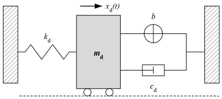
As illustrated in Figure 1, the TVMD consists of a tuned mass, a viscous damper, a tuning spring, and an inerter connected in parallel. The interaction force fd(t) and the dynamic equilibrium equation of the tuned mass are governed by:
f d ( t ) = b ( x ¨ d ( t ) x ¨ n ( t ) ) + c d ( x ˙ d ( t ) x ˙ n ( t ) ) + k d ( x d ( t ) x n ( t ) )
( m d + b ) x ¨ d ( t ) b x ¨ n ( t ) + c d ( x ˙ d ( t ) x ˙ n ( t ) ) + k d ( x d ( t ) x n ( t ) ) = 0
where md is the physical mass of the tuned block, b represents the apparent mass (inertance) provided by the inerter device, cd is the viscous damping coefficient, kd is the stiffness coefficient of the tuning spring, xd(t) denotes the absolute displacement of the tuned mass, and xn(t) is the absolute displacement of the n-th floor.

2.2. Device Imperfection Modeling

2.2.1. Manufacturing Tolerance in Inertance and Stiffness

In practical engineering applications, the mechanical parameters of the TVMD inevitably deviate from their idealized design values due to machining precision limitations and assembly tolerances. Since the tuning frequency of the device is primarily governed by the inertance and stiffness, their respective uncertainties are modeled as bounded fractional errors:
b = b n o m ( 1 + δ b )
k d = k n o m ( 1 + δ k )
where bnom and knom are the nominal design values of the inertance and stiffness, respectively and δb and δk represent the unknown but bounded dimensionless fractional errors for the inertance and stiffness, reflecting the actual manufacturing tolerances.

2.2.2. Nonlinear Friction and Dead-Zone Effect

The mechanical transmission mechanisms within the inerter, such as rack-and-pinion gears or ball screws, inevitably introduce parasitic nonlinear friction. This friction can temporarily lock the device during zero-crossing velocity phases, leading to a dead-zone effect that deteriorates the vibration mitigation efficiency under low-amplitude wind excitations. The nonlinear friction force ffr(t) is incorporated using a modified Coulomb friction model [41]:
f f r ( t ) = F y sgn ( x ˙ d ( t ) x ˙ n ( t ) )
where Fy is the yielding friction force inherently determined by the mechanical assembly and gear pre-tightening, sgn() is the standard signum function and x ˙ d ( t )   x ˙ n ( t ) represents the relative velocity between the tuned mass and the primary structure.

2.2.3. Thermal Drift of Viscous Damping

The damping properties of TVMDs are highly sensitive to the operating temperature due to the thermophysical characteristics of the viscous fluid. Based on the Arrhenius relationship [42], the temperature-dependent damping coefficient c(T) is formulated as:
c ( T ) = c n o m exp β 1 T 1 T r e f
where cnom denotes the nominal damping coefficient at the reference temperature Tref (typically 293.15 K); T is the instantaneous absolute temperature; and β represents the temperature sensitivity coefficient related to the fluid’s activation energy. This model captures the exponential decay of damping capacity under extreme thermal conditions.

2.2.4. Long-Term Degradation

Over a decades-long service life, the TVMD inevitably undergoes performance degradation caused by seal aging, fluid oxidation, or minor leakage. To reflect the time-dependent reliability, an empirical power-law degradation model is adopted [43]:
c ( t ) = c 0 ( 1 λ t η )
where c(t) is the damping coefficient at year t; c0 is the initial damping value; λ denotes the degradation rate coefficient; and η is the aging exponent. The parameter η < 1 represents a decelerating degradation process, which is consistent with observed trends in accelerated aging tests of high-performance dampers.

2.2.5. Scope of Uncertainty Modeling and Justification

The IGDT uncertainty model in this study focuses on inertance and stiffness because these two parameters directly determine the TVMD tuning frequency through the stiffness-to-inertance ratio. Opposite-sign deviations in b and k therefore shift the resonance condition most strongly and generate the dangerous-diagonal sensitivity pattern characterized in Section 3.4. They are consequently selected as the primary epistemic manufacturing variables for the robustness-radius search.
Other practical imperfections are not ignored, but they are treated according to their physical roles. Damping variation is represented through the thermal drift and long-term degradation models in Section 2.2.3 and Section 2.2.4, and is further evaluated in the full-lifetime analysis in Section 4.4. Nonlinear friction is explicitly included in Section 2.2.2, but its dominant effect occurs during low-amplitude and zero-crossing velocity phases rather than through the central tuning-frequency ratio. Installation errors may be equivalent to support flexibility, eccentricity, or connection-stiffness uncertainty. They are therefore identified as an important extension for future multi-parameter IGDT modeling in Section 6.3.

2.3. Wind Excitation Model

The along-wind dynamic loads are modeled as a stationary multi-variate Gaussian stochastic process. The fluctuating wind force acting on the i-th floor is derived from the mean wind velocity profile and the spatial correlation of the wind field. The cross-power spectral density (PSD) function between the fluctuating wind forces on the i-th and j-th floors is defined as:
S F i F j ( ω ) = 4 P ¯ i P ¯ j v ¯ i v ¯ j S v ( ω ) Coh i j ( ω )
where P ¯ i and P ¯ j are the mean wind forces acting on the i-th and j-th floors, respectively, v ¯ i and v ¯ j denote the mean wind velocities at the corresponding elevations, Sv(ω) is the Davenport empirical wind velocity spectrum representing the energy distribution of wind turbulence in the frequency domain [44], and Cohij(ω) is the spatial coherence function describing the cross-correlation of wind fluctuations between different spatial elevations [45].

2.4. H2-Optimal Design Baseline

A nominal H2-optimal design is first formulated as the performance benchmark for the subsequent robustness evaluations. The objective is to minimize the root-mean-square (RMS) response of the top-floor acceleration under nominal conditions (i.e., devoid of any manufacturing defects or degradation). The nominal optimization problem is mathematically defined as:
J H 2 = min X σ x ¨ n ( X )
subject to: X L X X U where J H 2 is the objective function representing the H2 norm of the structural response, σ x ¨ n denotes the RMS value of the top-floor acceleration, X =   [ μ , β , ν , ζ ] is the non-dimensional design variable vector for the TVMD (mass ratio, inertance ratio, frequency tuning ratio, and damping ratio), and XL and XU are the lower and upper bounds of the parameter search space defined by structural payload limitations and engineering feasibility.

3. Info-Gap Robust Optimization Framework

This study proposes an Info-Gap Decision Theory (IGDT) based robust optimization framework as its main methodological contribution. Unlike conventional Reliability-Based Design Optimization (RBDO) that relies on assumed prior probability distributions, this framework establishes a prior-data-independent tolerance reverse determination mechanism. It aims to quantify the maximum permissible manufacturing uncertainty envelope while maintaining the prescribed structural safety threshold.

3.1. Info-Gap Decision Theory

Info-Gap Decision Theory provides a non-probabilistic methodology for decision-making under severe uncertainty. An IGDT framework consists of three fundamental components: the system model, the performance requirement, and the uncertainty model.
In this study, the system model is the dynamic response of the TVMD-equipped structure evaluated via time-history analysis (Section 2.1). The performance requirement is defined by the critical comfort limit for the top-floor acceleration RMS. To characterize the bounded but unknown manufacturing errors in inertance and stiffness (as defined in Section 2.2.1), a fractional-error info-gap model is adopted:
U ( α , u ˜ ) = u ( b , k ) : b b n o m b n o m α , k k n o m k n o m α , α 0
where u(b, k) represents the actual physical parameters, bnom and knom are the nominal design variables, and α is the horizon of uncertainty (i.e., the robustness radius), defining the maximum relative fractional error permitted in the manufacturing process.

3.2. IGDT Optimization Problem Formulation

Robust design aims to maximize the system’s tolerance to uncertainty while satisfying the prescribed safety constraints. The IGDT robust optimization problem for the TVMD is formulated as maximizing the robustness radius α, such that the maximum dynamic response within the uncertainty envelope U(α) does not exceed the critical threshold Rc:
α ^ ( X , R c ) = max α : max u U ( α , u ˜ ) σ x n ( X , u ) R c
where X = [μ, β, ν, ζ] is the design variable vector of the TVMD, σxn denotes the peak top-floor acceleration, and Rc = 0.15 m/s2 is the peak acceleration comfort threshold prescribed by the ISO 10137 standard. The corresponding RMS equivalent is Rc, RMS = Rc/g = 0.15/3.33 ≈ 0.045 m/s2, where g is the simulation-consistent peak factor computed for the fundamental mode (ν ≈ 0.16 Hz, T = 600 s) [46]. The peak-based formulation is adopted here because ISO 10137 specifies a peak criterion directly; the RMS-based representation (Rc,RMS = 0.045 m/s2) is used in Section 4.5 for Monte Carlo verification. This formulation inherently serves as a reverse determination mechanism for engineering manufacturing, directly yielding the quantitative quality control standards without requiring prior fault data.
To prevent the robustness radius from being artificially enlarged by an overly loose absolute threshold alone, a dual-criterion constraint is imposed. In addition to the absolute comfort bound Rc = 0.15 m/s2, the worst-case peak acceleration within U(α) must not exceed η·σx0, where σx0 = 0.080 m/s2 is the nominal peak acceleration of the robust design under ideal conditions and η = 1.30 is a relative degradation limit permitting at most 30% performance deterioration. The binding constraint for each candidate design is therefore
max { σ x n X ,   u : u U α } min R c ,   η σ x 0

3.3. Bi-Level Solution Strategy

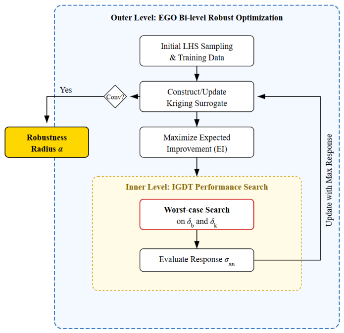
Solving the IGDT formulation requires a nested max-max problem, with α optimized in the outer loop and the worst-case dynamic response searched in the inner loop. To overcome the prohibitive computational cost of massive structural time-history analyses, this study introduces a Kriging-surrogate-assisted Efficient Global Optimization (EGO) bi-level strategy, as shown in Figure 2.
Inner-Level Worst-Case Search: For a given parameter set X and a specific radius α, an optimization sub-problem is solved to find the precise error combination (δb, δk) that triggers the most severe acceleration response.
Outer-Level EGO Optimization: A Kriging surrogate model is constructed to map the complex nonlinear relationship between the TVMD design parameters X and the inner-level maximum response. The EGO algorithm utilizes the Expected Improvement (EI) function to iteratively sample the most promising design points, thereby efficiently driving the search toward the global optimal robust parameters X ^ robust that yield the maximum α ^ .

3.4. Analytical Characterization of the Asymmetric Sensitivity Space

The performance sensitivity of the TVMD is governed by the ratio of its as-built stiffness to its as-built inertance. Substituting the imperfection models from Section 2.2 into the tuning frequency expression gives
ω a c t u a l = ω 0   [   ( 1 + δ k )   /   ( 1 + δ b )   ]
where ω0 = (knom/bnom)1/2 is the nominal tuning frequency, and δk and δb are the dimensionless fractional errors in stiffness and inertance, respectively. The frequency drift ratio is defined as ρ(δb, δk) = ωactual/ω0 − 1. The IGDT info-gap model bounds the two errors within the L box
U α = { ( δ b , δ k ) : | δ b α , δ k | α }
where α is the uncertainty horizon that the robust optimization seeks to maximize. Two directions within this box play a central role in the subsequent analysis. The dangerous diagonal denotes the locus where δk and δb carry opposite signs, so that a positive stiffness error is paired with a negative inertance error or vice versa. The safe diagonal denotes the locus where both errors carry the same sign. The physical consequences of these two directions are established in closed form in the paragraphs that follow.
The worst-case frequency drift within U(α) is determined by identifying the parameter pair (δb, δk) that maximises |ρ|. Because ρ is monotonically increasing in δk and monotonically decreasing in δb, the maximum is achieved at the box corner where δk = +α and δb = −α, with the symmetric corner (δb, δk) = (+α, −α) yielding the same magnitude. Both corners lie exclusively on the dangerous diagonal, giving the closed-form result.
| ρ | m a x = 1 + α / 1 α 1
A complementary result holds along the safe diagonal. Setting δk = δb = δ for any δ in the admissible range gives ρ(δ, δ) = [(1 + δ)/(1 + δ)]1/2 − 1 = 0. The frequency drift is therefore identically zero along the entire safe diagonal, regardless of the error magnitude. This result reveals why same-sign manufacturing errors are physically benign. When stiffness and inertance deviate proportionally in the same direction, the ratio k/b is preserved exactly, and the resonance condition between the TVMD and the primary structure remains intact.
The preceding results allow the underestimation error of symmetric uncertainty models to be quantified exactly. A symmetric L2 ball U2(α) = {δk2 + δb2 ≤ α2} has the same maximum per-coordinate deviation α as the L box but distributes the uncertainty budget isotropically. Maximising |ρ| on the L2 boundary via Lagrange multipliers gives the worst-case point (δb, δk) with drift |ρ|2,max. The underestimation ratio of the symmetric model relative to the L info-gap box is
η u n d e r α = ρ , max ρ 2 , max = 1 + α / 1 α 1   1 + α / 2 / 1 α / 2 1 2
The inequality holds strictly for all α ∈ (0, 1), with asymptotic equality as α → 0. The symmetric model underestimates the worst-case frequency drift by more than 40% at any practically relevant uncertainty level. The 30% performance underestimation reported in Section 4.3 is lower than the frequency-drift underestimation because the nonlinear transfer function from frequency drift to acceleration RMS introduces a saturation effect at large detuning amplitudes. Nevertheless, the analytical inequality in Equation (17) provides a rigorous lower bound that holds independently of the structural model and is therefore directly applicable to the general class of inerter-based absorbers whose tuning frequency is governed by a stiffness-to-inertance ratio.

4. Numerical Case Study

4.1. Benchmark Building Description

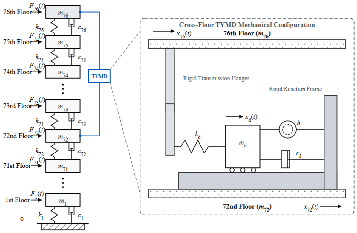
The proposed IGDT-EGO robust design framework is evaluated using a classical 76-story super-tall office-building benchmark [47]. The building, with a total height of 306 m and an aspect ratio of 7.3, is a widely recognized standard model for evaluating complex structural control systems. The dynamic characteristics of the structure are fully depicted by the mass matrix M, the stiffness matrix K, and the damping matrix C established on the Rayleigh damping assumption. The schematic diagram of the MDOF structure with TVMD is illustrated in Figure 3, where the device is cross-floor installed between the 76th and 72nd floors. This specific arrangement is selected to capture a larger inter-story stroke, thereby maximizing the mass-amplification effect of the inerter and enhancing the control efficiency. The structure exhibits significant flexibility, with a fundamental natural frequency of approximately 0.16 Hz.
Additional modeling information is summarized in Table 1 to clarify the structural assumptions used in the case study. The benchmark is an equivalent multi-degree-of-freedom shear-building model developed for wind-excited response-control studies rather than a site-specific architectural project. Therefore, the original benchmark does not prescribe a detailed architectural floor plan, reinforced-core layout, or material grade for a real building. Their effects are instead represented by the floor-wise mass, stiffness, and damping matrices. The structural axes are taken as the centroidal along-wind and cross-wind axes of the equivalent model, and the wind excitation is applied along the governing along-wind direction. Because the benchmark is not associated with a particular geographic site, a site-specific wind rose is not introduced in the present analysis. Future applications to real projects can combine the proposed IGDT framework with local wind-rose data and multi-directional wind loading.
In practical installation, the rigid transmission hanger in Figure 3 is not a freely suspended non-structural element. It represents a steel force-transfer component that can be realized as a high-stiffness rod, box-section link, or paired tension-compression member. The upper end may be anchored to a collector beam, embedded plate, or strengthened core-wall/outrigger region at the upper floor, while the reaction frame of the TVMD is fixed to the lower floor or adjacent structural zone. The lower end of the hanger is connected to the TVMD moving block through a pinned or spherical joint to reduce unintended bending. Its axial stiffness should be sufficiently larger than the equivalent TVMD stiffness so that the hanger flexibility does not alter the tuning frequency. For full-scale implementation, local floor beams, embedded plates, and reaction-frame anchors should be verified through detailed finite-element connection design.
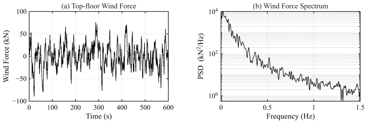
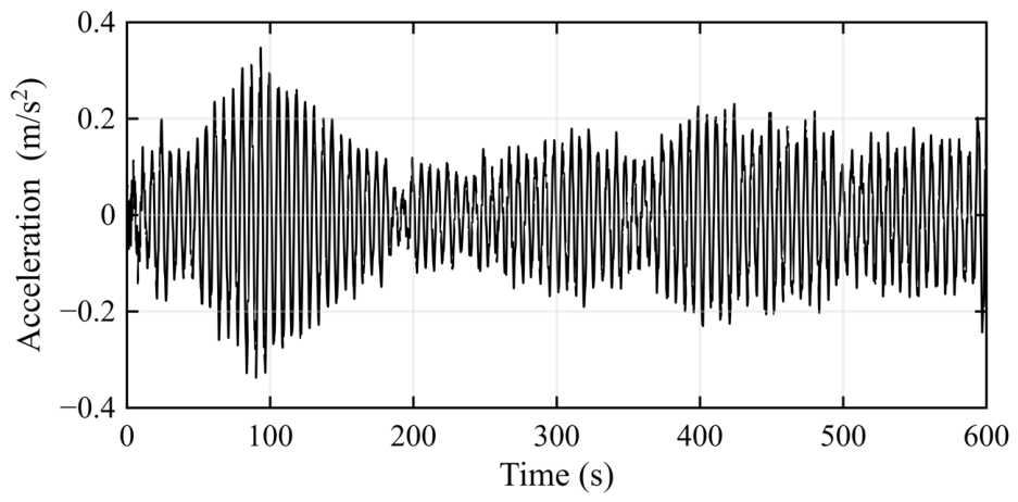
In the numerical simulation, the wind load is modeled as a non-stationary stochastic process acting on each individual floor, obtained from scaled wind tunnel tests [48]. Figure 4 displays the time history and the Power Spectral Density (PSD) of the wind excitation at the top floor. As shown in Figure 4b, the wind energy is densely concentrated in the low-frequency region, which heavily overlaps with the fundamental frequency of the benchmark building, thereby easily triggering severe resonant responses.
To establish a baseline for evaluating the vibration mitigation performance, the dynamic response of the building without any control system was first simulated. The simulation time step is set to Δt = 0.01 s, and the total duration is 600 s. As depicted in Figure 5, the uncontrolled top-floor acceleration time history reveals that the peak acceleration reaches approximately 0.35 m/s2, significantly exceeding the 0.15 m/s2 human comfort limit specified by the ISO 10137 standard. This severe wind-induced vibration underscores the urgent necessity of deploying the TVMD system. The subsequent optimizations and robust analyses in Section 4.2, Section 4.3, Section 4.4 and Section 4.5 will all be evaluated against this uncontrolled baseline.

4.2. Nominal H2-Optimal TVMD Design

In this study, the primary objective of the nominal optimal design is to establish a parameter baseline for the TVMD under ideal conditions without uncertainties. To achieve this, a Genetic Algorithm (GA) is employed to minimize the root-mean-square (RMS) value of the top-floor acceleration of the 76-story benchmark building within a four-dimensional design space [49]. The search boundaries are strictly defined based on engineering practice and literature consensus: mass ratio μ ϵ [0.001, 0.005], inertance ratio β ϵ [0.01, 1.00], frequency tuning ratio υ ϵ [0.50, 1.50], and damping ratio η ϵ [0.01, 0.50]. To capture the global optimal energy dissipation path of the TVMD system under stochastic wind excitations, the optimization is executed within a parallel computing environment.
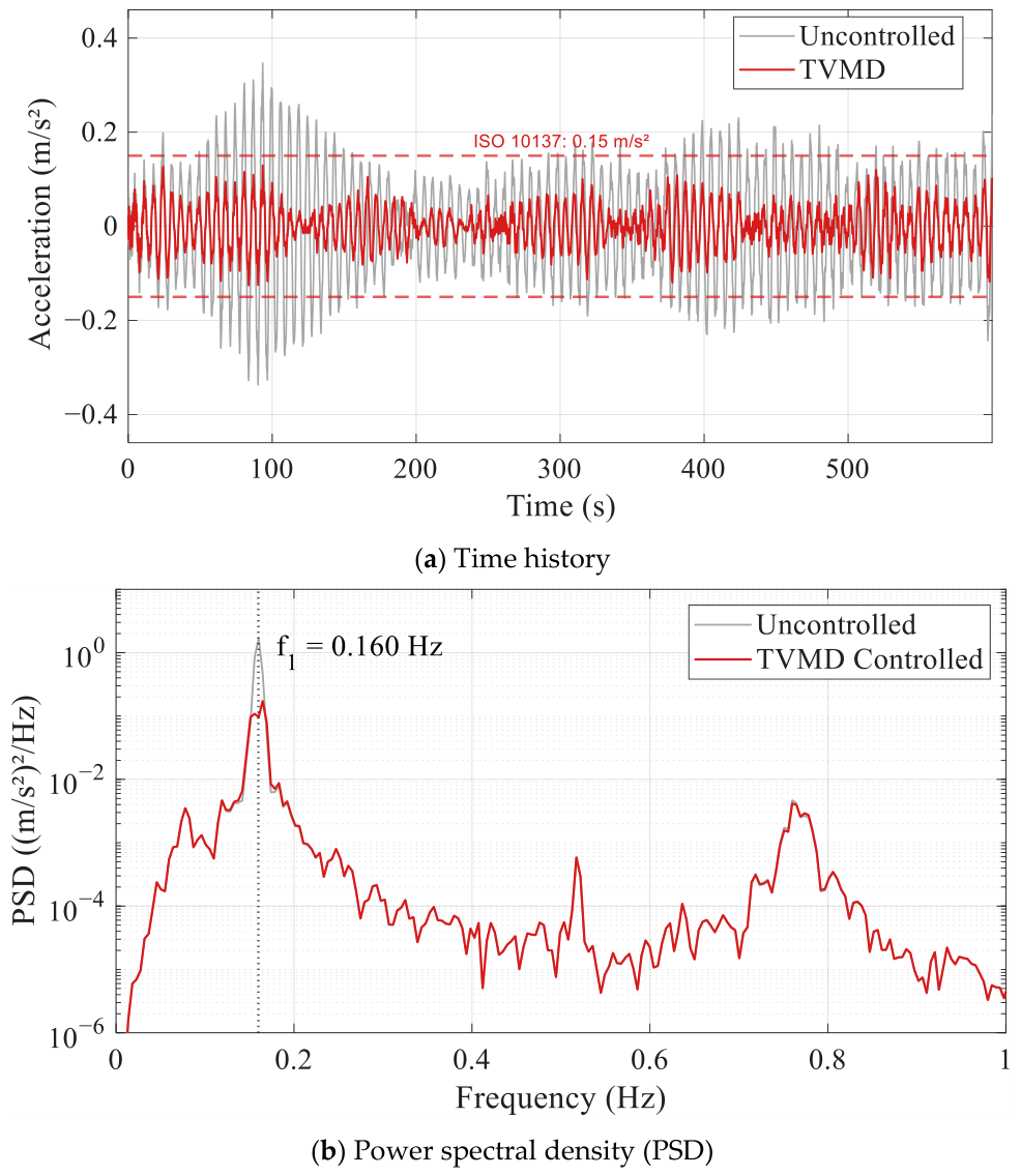
Following the convergence of the algorithm, the nominal optimal design vector is determined as Xnom = [0.005, 0.8120, 0.9858, 0.0246]. Under this configuration, the top-floor acceleration RMS is reduced to 0.03204 m/s2. Notably, the algorithm converges to μ = 0.5%, indicating that the TVMD can achieve effective control with a small physical mass ratio that complies with the payload restrictions of super-tall buildings. To further reveal the frequency-domain mitigation mechanism of this optimal design, Figure 6 compares the time history and the power spectral density (PSD) of the top-floor acceleration between the uncontrolled and controlled states. The results show that the nominal optimal TVMD clearly suppresses the primary resonant peak at the structural fundamental frequency of approximately 0.16 Hz, without inducing adverse coupling effects on higher modes.
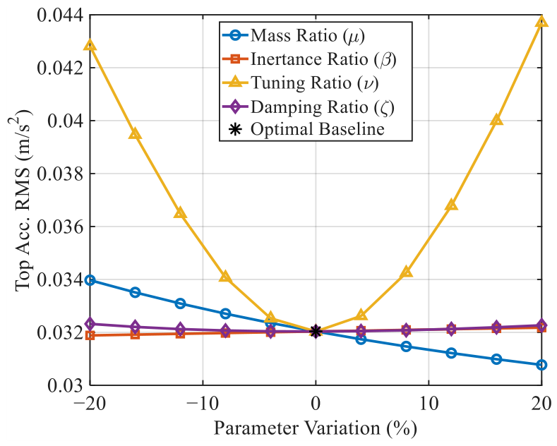
While the nominal H2-optimal design exhibits excellent vibration suppression at the theoretical level, its performance relies heavily on the exact matching of physical parameters. Figure 7 presents a univariate sensitivity analysis of the system’s RMS performance subjected to parameter perturbations within a ±20% range around the optimal point. As depicted, the system is extremely sensitive to deviations in the tuning ratio υ, exhibiting a steep “V-shaped” degradation trend; even a 10% detuning causes the RMS to deteriorate rapidly. Considering that manufacturing tolerances, thermal drift, and long-term degradation (as discussed in Section 2.2) will inevitably induce parameter drifts, this highly “tuned” state is highly vulnerable in actual engineering environments. Therefore, the nominal optimal solution only serves as a performance “upper bound”. Information-Gap Decision Theory (IGDT) is therefore introduced in the following sections to evaluate robustness under severe uncertainty and to obtain a design with stronger degradation resistance.

4.3. IGDT Robust Design Results

This section presents and discusses the numerical results regarding the robust optimization of the TVMD for a 76-story benchmark building using the EGO algorithm. The optimization objective is to maximize the tolerance of the system to manufacturing uncertainties, referred to as the robustness radius α, subject to the dual-criterion constraint defined in Section 3.2: the worst-case peak acceleration must not exceed the ISO 10137 limit of Rc = 0.15 m/s2 and must simultaneously remain within 30% of the nominal peak response.
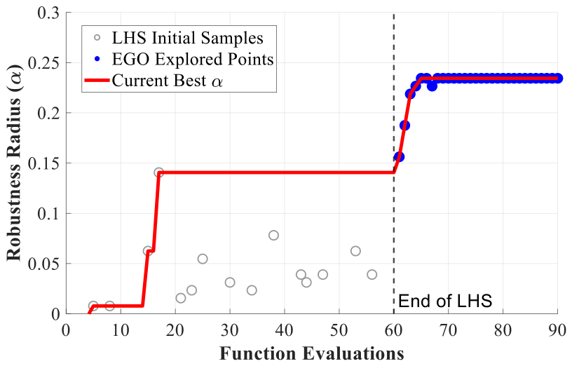
Figure 8 illustrates the convergence history of the EGO algorithm during the optimization process. In the initial stage of 60 Latin Hypercube Sampling evaluations, the sample points are broadly distributed across the parameter space to construct a global approximation for the Kriging surrogate model. After entering the EGO iteration phase, the algorithm updates the surrogate model by maximizing the Expected Improvement function. The best historical value of the robustness radius α increases stepwise and then converges steadily to α = 0.2344 after the EGO iterations, which corresponds to a certified manufacturing uncertainty horizon of 23.44%. This convergence behavior indicates that the surrogate-model-assisted optimization strategy efficiently identifies the robust design point while reducing the number of high-fidelity dynamic evaluations.
To make the efficiency gain explicit, Table 2 compares the proposed Kriging-EGO strategy with representative conventional search strategies under the same design domain. The values are reported as approximate high-fidelity time-history evaluation counts, because the exact number depends on the stopping tolerance of the inner worst-case search and the hardware platform. The comparison shows that the proposed strategy reaches the same robustness horizon with a substantially lower computational burden.
Upon convergence, the robust optimal design vector is determined as Xrobust = [μ, β, ν, ζ] = [0.0048, 0.8500, 1.3177, 0.2985]. Compared with the nominal H2-optimal parameters Xnom = [0.005, 0.8120, 0.9858, 0.0246], the robust design retains a comparable inertance ratio while adopting a markedly higher frequency tuning ratio (ν = 1.3177 vs. 0.9858) and a substantially larger damping ratio (ζ = 0.2985 vs. 0.0246), reflecting the deliberate broadening of the energy dissipation bandwidth that underpins the improved robustness at the cost of a marginal reduction in nominal peak performance.
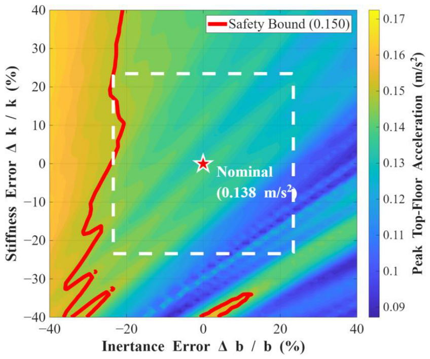
The manufacturing tolerance-performance contour map is provided in Figure 9 to further reveal the physical characteristics and the resistance mechanisms against uncertainty for the optimal TVMD design. The red pentagram in the figure represents the robust optimal design point under error-free conditions, at which the peak top-floor acceleration is 0.1384 m/s2—well below the ISO 10137 comfort threshold of 0.15 m/s2 and the 30% degradation limit of 0.15 m/s2. The maximum robustness region determined by the IGDT algorithm is illustrated by the white dashed box in the figure. Its boundary is governed by the binding constraint in the dangerous-diagonal direction, where opposite-sign manufacturing errors produce the most severe frequency detuning. This geometric relationship demonstrates that ISO 10137 comfort compliance is maintained for any combination of inertance and stiffness errors within a fractional bound of α = 0.2344, equivalent to 23.44%. The white dashed box therefore corresponds to δb and δk falling between −0.2344 and 0.2344, namely ±23.44% manufacturing uncertainty in both inertance and stiffness.
It is noteworthy that the distribution of the contours exhibits a pronounced asymmetry. The variation in response is relatively gradual in the direction of the safe diagonal where Δb and Δk change with the same sign. In contrast, the contours are extremely dense in the direction of the dangerous diagonal where Δb and Δk change with opposite signs, and the response rapidly approaches the red boundary. This reveals a critical feature of the TVMD physical mechanism where opposite shifts in inertance and stiffness lead to the most severe drift in the tuning frequency, resulting in a significantly enhanced detuning effect. The IGDT algorithm identifies this worst-case scenario and provides a quantitative and safe tolerance specification for engineering manufacturing.

4.4. Full-Lifetime Performance Analysis

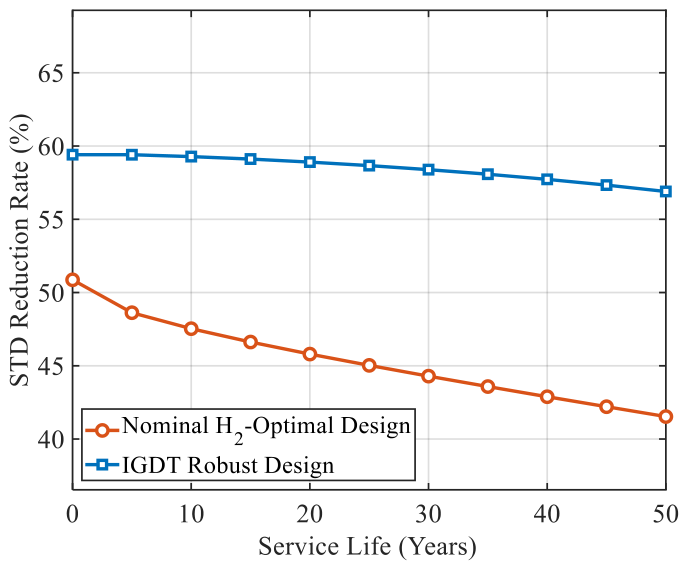
To evaluate the long-term reliability of the TVMD system, a full-lifetime dynamic analysis was conducted by coupling the device imperfection models in Section 2.2. Crucially, rather than applying a benign single-parameter error, this evaluation incorporates the worst-case scenario identified in the IGDT analysis: a coupled manufacturing tolerance along the “dangerous diagonal” (e.g., a simultaneous +20% shift in inertance and −20% shift in stiffness), which induces a severe frequency detuning of approximately −34.6%. This initial defect is then compounded with a 50-year severe empirical power-law degradation and Arrhenius thermal drift.
Figure 10 illustrates the evolution of the top-floor acceleration STD reduction rate at a nominal 20 °C over 50 years. Exposed to the initial detuning penalty, the nominal H2-optimal design suffers a drastic performance collapse right at Year 0, dropping to approximately 51% efficiency, followed by a continuous deterioration path. In sharp contrast, the IGDT robust design, shielded by its large robustness radius (α = 0.2344), completely absorbs the combined manufacturing defects. At 20 °C, the IGDT robust design maintains a stable reduction rate of approximately 56.9% at Year 50 and remains above 50% throughout the half-century service life.
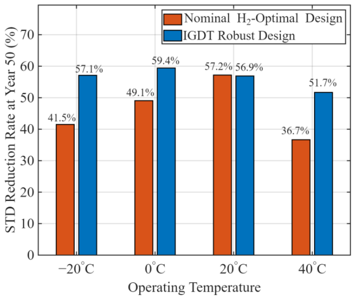
To further investigate the system’s endurance limit, Figure 11 extracts the performance at the very end of the service life (Year 50) across extreme operating temperatures. Under the ultimate multi-hazard combination (severe aging coupled with 40 °C thermal drift and initial detuning), the nominal design’s efficiency plummets to a mere 36.7%, posing a severe risk of violating the 0.15 m/s2 comfort threshold. Conversely, the robust design firmly secures a reduction rate of 51.7%, proving that the IGDT framework successfully immunizes the structural control system against the dual threats of initial manufacturing uncertainty and long-term environmental degradation.

4.5. Comparative Analysis

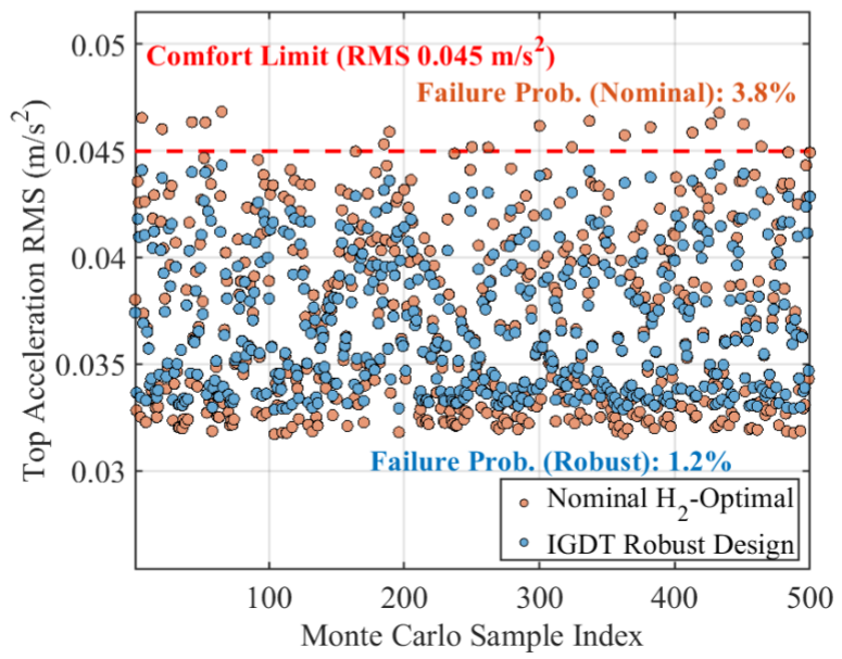
To systematically verify the reliability of the robust parameters derived from the non-probabilistic IGDT framework under realistic random uncertainties, a Comparative Monte Carlo Simulation (MCS) was conducted in this section. Considering the coupled effects of extreme manufacturing defects in practical engineering, the simulation injected ±20% random manufacturing tolerances, assuming a uniform distribution, directly into the physical stiffness and inertance matrices of the system. By executing 500 random time-history samples for both the nominal H2-optimal design and the IGDT robust design, the performance evolution characteristics of the two schemes were comprehensively evaluated against the RMS-equivalent comfort threshold of Rc,RMS = 0.045 m/s2, derived from the ISO 10137 peak limit of 0.15 m/s2 using the simulation-consistent peak factor g ≈ 3.33 (see Section 3.2).
Figure 12 presents the scatter cloud of the top-floor acceleration RMS for all 500 samples subjected to random physical perturbations. The nominal design (orange markers) achieves lower baseline responses in near-ideal cases, but its response dispersion increases markedly when coupled errors are introduced, causing many samples to exceed the 0.045 m/s2 safety threshold. Conversely, the IGDT robust design (blue markers) demonstrates an extraordinary capability in dispersion control. By broadening the energy dissipation bandwidth of the system, the robust design successfully absorbs the shocks of extreme physical detuning, strictly compressing the dynamic responses under worst-case scenarios within the safety envelope.
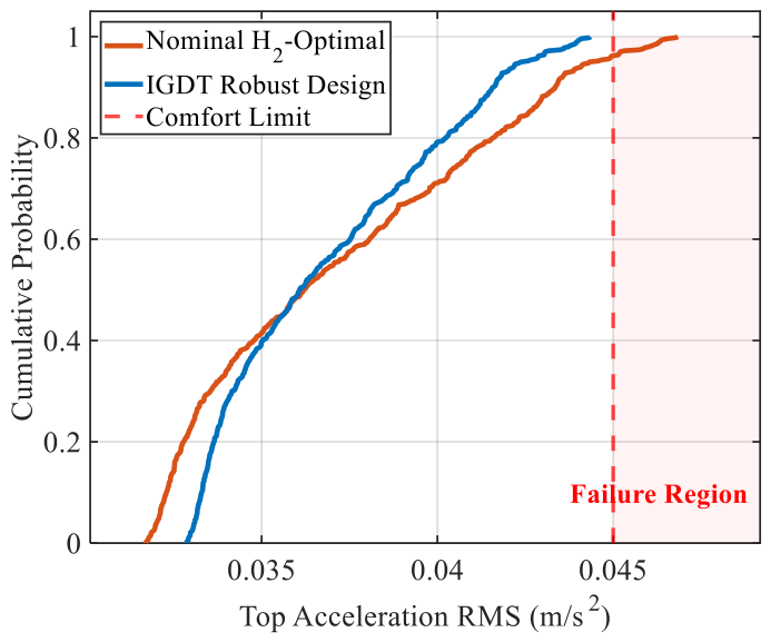
The empirical cumulative distribution functions (CDFs) in Figure 13 further illustrate the performance–robustness trade-off in robust control. The CDF curve of the nominal design holds an advantage on the left side (low-error region); however, due to its extremely narrow tuning band, the curve exhibits a pronounced “long-tail effect” on the right side. This long tail drags deep into the failure region, ultimately resulting in a failure probability of 3.8%. In sharp contrast, the robust design proactively endures a slight baseline performance penalty (indicated by a slightly higher starting point of the curve) in exchange for absolute suppression of extreme tail risks. The robust CDF curve intersects and inverts in the middle section, cutting off the disastrous long tail with a steeply rising posture, which dramatically reduces the failure probability to 1.2%. This comparative result indicates that the proposed IGDT optimization framework shifts the system from a fragile peak toward a robust plateau, providing a fail-safe design mechanism for supertall buildings exposed to lifecycle uncertainties.

5. Experimental Validation

5.1. Experiment Setup

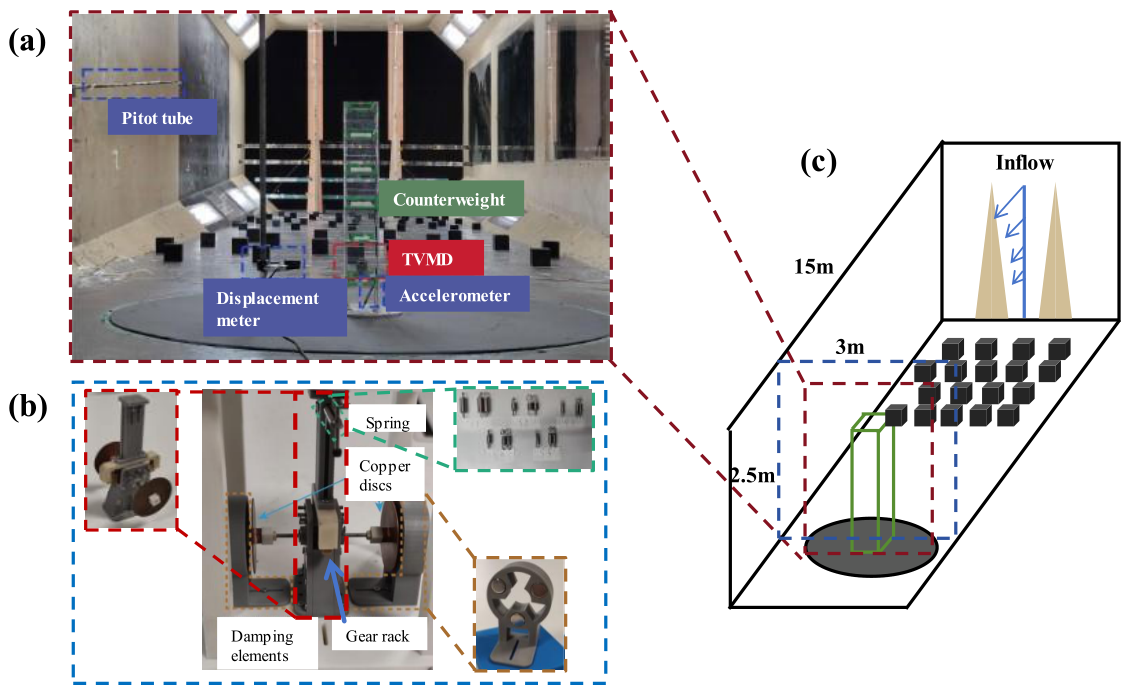
To bridge the theoretical robustness boundaries derived in Section 4 with physical evidence, a comprehensive aeroelastic wind tunnel testing program was conducted. The overall experimental arrangement and the core control hardware are illustrated in Figure 14.
First, a 1:350 geometric scale aeroelastic model was fabricated to replicate the dynamic characteristics of the 76-story benchmark structure (Figure 14a) [48]. The structural frame utilizes four aluminum alloy columns to provide target lateral stiffness, embodying the shear beam idealization used in the numerical modeling. The core control mechanism is a purpose-designed electromagnetic-tuned viscous mass damper (ETVMD) prototype, whose detailed mechanical configuration is presented in Figure 14b. The device employs a high-precision gear-rack mechanism to drive rotating copper flywheels, achieving a mass amplification factor exceeding 50, while N52 permanent magnets provide adjustable non-contact eddy current damping [50].
Testing was performed in the TJ-2 Atmospheric Boundary Layer Wind Tunnel at Tongji University. The TJ-2 facility is a transverse-return low-speed atmospheric boundary layer wind tunnel with a test section of 3.0 m width, 2.5 m height, and 15.0 m length. The empty-tunnel wind speed can be continuously adjusted from 0.5 to 68 m/s. The facility is equipped with automatic speed regulation, control and data-acquisition systems, and an automatic turntable for building-structure model tests. Under uniform-flow calibration, the velocity non-uniformity is less than 1%, the turbulence intensity is less than 0.46%, and the mean flow yaw angle is less than 0.5° [51]. In the present test, the boundary layer was generated using the spires and roughness elements shown in Figure 14c, and the aeroelastic response was recorded by acceleration and displacement sensors arranged near the top region of the model. The 1:350 geometric scale and the 3.0 m × 2.5 m test-section area kept the model blockage at a level suitable for aeroelastic validation.
To encapsulate the uncertainty space investigated by the IGDT analysis, a comprehensive test matrix comprising 620 unique configurations was implemented. By systematically varying the spring stiffnesses and disc quantities, the program artificially constructed a wide spectrum of physical detuning cases, providing a statistical basis for validating the robust performance of the TVMD system.

5.2. Parameter Configuration and Uncertainty Simulation

To establish a rigorous cross-validation between the numerical optimization and the experimental results, two distinct parameter sets were selected as the benchmarks for testing: the Nominal H2 Configuration and the Robust IGDT Configuration. The nominal configuration corresponds to the standard H2-optimal design, which prioritizes peak vibration suppression under ideal conditions. In contrast, the robust configuration is derived from the IGDT-EGO framework, which intentionally trades a marginal fraction of its baseline efficiency for a broader energy dissipation bandwidth. The specific mechanical parameters of these two paradigms, as implemented in the ETVMD prototype, are summarized in Table 3 [52].
Specifically, the selection of five spring groups (S1–S5) acts as a physical proxy for the frequency ratio uncertainty (υ). As summarized in Table 4, these springs generate a frequency detuning range of approximately ±50% relative to the nominal H2-optimal configuration (S2). Similarly, the adjustment of copper disc quantities (0.5, 1, 1.5, 2 and 3 discs) simulates the uncertainty in the inertance ratio (β), representing a ± 50% deviation from the median inertance level. Furthermore, the variation in the damping ratio (ζ) is realized by adjusting the air gap of the permanent magnets [53]. This directly modulates the intensity of the eddy current, serving as a physical proxy for damping uncertainties typically caused by the aging of viscous fluids or the degradation of magnetic fields over the building’s lifespan.
It should be noted that while the structural uncertainties (α) investigated in the theoretical analysis are continuous, the experimental validation relies on a discrete sampling strategy. To ensure the fidelity of this physical simulation, the perturbation increments provided by the S1–S5 spring sequences and the half-thickness discs were carefully calibrated to capture the critical nonlinear inflection points of the performance degradation curves. By accumulating 620 unique experimental samples, a sufficiently dense “response surface” is established in the physical domain. This allows the discrete wind tunnel observations to effectively approximate the continuous robustness envelopes defined by the IGDT-EGO framework, ensuring that the worst-case scenarios predicted mathematically are effectively encapsulated within the experimental search space.

5.3. Comparative Validation of Robustness Under Parameter Detuning

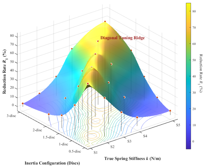
To experimentally investigate the system’s global sensitivity to manufacturing uncertainties, the comprehensive full-factorial wind tunnel dataset was utilized to reconstruct the performance degradation response surface in the physical domain. Figure 15 illustrates the three-dimensional topology of the reduction efficiency (R1) plotted against the true physical spring stiffness and inertance configurations.
The experimental topography explicitly exhibits a prominent diagonal tuning ridge spanning across the parameter space. This topographical feature physicalizes the fundamental dynamic tuning condition. Specifically, as the equivalent inertance (b) increases, the spring stiffness (k) must increase proportionally to maintain resonance with the primary structure. Furthermore, an asymptotic saturation phenomenon is clearly observed along the ridge crest. The peak efficiency climbs from 71.9% at the 1-disc/S2 configuration to 73.2% at the 2-disc/S4 configuration. However, further increasing the inertance to the 3-disc/S5 configuration yields a severely diminished marginal gain and plateaus near 66.8%. This progression strongly corroborates that excessive inertance limits relative motion and validates the necessity of finding a balanced parameter trade-off rather than blindly maximizing apparent mass.
More importantly, the high-resolution surface provides direct experimental evidence for the asymmetric sensitivity space. The response surface forms a steep topographical canyon along the true stiffness axis. Fixing the inertance at the 1-disc baseline and perturbing the stiffness from S2 to S1 causes a marked performance drop from 71.9% to below 35.0%. Conversely, perturbing the inertance while fixing the stiffness induces a noticeably shallower degradation slope. This experimental observation supports the theoretical sensitivity hierarchy established in Section 4.3. It confirms that stiffness-induced frequency detuning is a critical vulnerability of the ETVMD system. Consequently, these findings support the core objective of the proposed IGDT framework, which is to prioritize frequency robustness and flatten this dangerous sensitivity canyon.
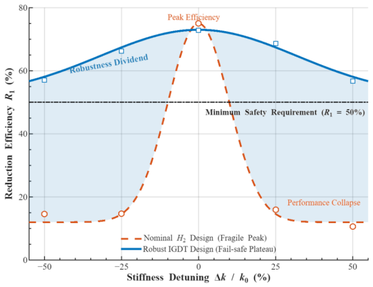
To compare the two design paradigms, Figure 16 extracts the critical degradation trajectories along the stiffness-detuning axis and contrasts the robustness envelopes of the nominal H2 and IGDT configurations. The visualization distinctly captures the fundamental trade-off between absolute optimality and environmental adaptability. The H2-optimized system exhibits a characteristic fragile peak. While it achieves a marginally superior reduction rate under idealized perfect tuning conditions, its control authority collapses precipitously once the stiffness deviation exceeds ±15%, plummeting well below the fundamental engineering safety threshold.
In stark contrast, the IGDT-derived configuration successfully transforms this fragile peak into a fail-safe performance plateau. By actively integrating higher levels of electromagnetic damping and inertance, the IGDT framework sacrifices an inconsequential fraction of the peak efficiency to secure a massive robustness dividend. As delineated by the shaded region in the figure, the robust design maintains a structural reduction efficiency above 50% even under severe ±50% structural stiffness degradations. This comparative evidence suggests that the proposed IGDT framework is more suitable for practical civil engineering applications in which long-term material aging and initial manufacturing tolerances make idealized H2 nominal conditions difficult to maintain.

5.4. Quantitative Comparison Between Numerical and Experimental Results

To provide a direct numerical-experimental comparison, a representative subset of counterpart cases was selected from the paired simulation and wind tunnel datasets. The comparison uses the vibration reduction efficiency R1 as the common metric because it is scale-independent and is reported consistently in both the numerical and aeroelastic models. The selected cases cover the nominal H2 peak, the IGDT robust center, the high-inertance saturation region, the dangerous stiffness-detuning path, and the robust plateau under large stiffness deviations.
For each counterpart case, the absolute difference is defined as ΔR = |RsimRexp|, where Rsim and Rexp denote the numerical and experimental reduction efficiencies, respectively. The comparison is summarized in Table 5.
Across these seven counterpart cases, the mean absolute difference between numerical and experimental reduction efficiencies is 1.29 percentage points, the maximum absolute difference is 1.70 percentage points, and the coefficient of determination is R2 = 0.994. These deviations are small relative to the performance changes caused by dangerous detuning, such as the drop from 71.9% to below 35.0% for the H2 configuration and the maintenance of a reduction efficiency above 50% for the IGDT configuration under large stiffness deviations. The numerical model therefore reproduces not only the qualitative topology of the experimental response surface, but also the main quantitative levels of the measured reduction efficiencies.
The remaining discrepancies are mainly attributed to discrete spring and disc realization in the prototype, small fabrication tolerances of the aeroelastic model, sensor noise, and the frequency-dependent behavior of the eddy-current damping mechanism. These differences do not alter the central conclusion that the numerical IGDT prediction and the wind tunnel observations consistently identify the same robustness mechanism: the nominal H2 design behaves as a narrow fragile peak, whereas the IGDT design forms a wider fail-safe performance plateau.

6. Discussion

6.1. Engineering Interpretation of Tolerance Specifications for IGDT-Based Design

The robust design obtained through the IGDT method in this study not only pursues the maximization of nominal performance but more importantly provides quantified manufacturing tolerance specifications for engineering practice. Since the vibration reduction efficiency of the TVMD is highly dependent on the precise matching of the inertance coefficient b and the stiffness coefficient k, the robustness radius α serves as a critical bridge connecting theoretical design with physical implementation. From the perspective of quality control, the robustness region defined in Figure 9 allows engineers to establish uniform tolerance grades for subsystem components, which simplifies the complexity of supply chain management while ensuring performance reliability.
The distribution patterns of the response contours reveal the directional dependency of structural dynamic sensitivity on combinations of uncertainties. In the diagonal direction where the inertance and stiffness errors change with the same sign, the system exhibits strong robust characteristics because the deviation of the tuning frequency is relatively small. In sharp contrast, when parameters undergo opposite shifts, the frequency detuning effect is rapidly amplified and leads to a severe deterioration in vibration reduction efficiency. This asymmetric sensitivity space provides an important physical basis for formulating differentiated manufacturing standards.
It should be emphasized that α = 0.2344 is not a recommended manufacturing error target and should not be interpreted as permission for loose fabrication. It is a certified safety envelope obtained from a worst-case search. Within this envelope, the design is expected to maintain the prescribed comfort performance even when the most unfavorable combination of inertance and stiffness errors occurs. In practical quality control, this means that component acceptance should not only check the separate deviations of b and k, but should also monitor the realized stiffness-to-inertance ratio. When the two parameters deviate in opposite directions, a tighter inspection criterion is required because the tuning-frequency error is amplified.
This failure-boundary-based tolerance setting method reflects the Cannikin Law in engineering design, because the overall reliability of the system is governed by the most adverse detuning direction rather than by average manufacturing quality. Compared with probabilistic optimization methods that require large amounts of statistical data, IGDT provides a direct way to identify the limiting uncertainty horizon when prior information is scarce. By exploiting the robustness radius of α = 0.2344, equivalent to a 23.44% manufacturing uncertainty horizon, engineers can formulate differentiated tolerance specifications. Same-sign deviations of inertance and stiffness are less harmful because the ratio k/b is approximately preserved. Opposite-sign deviations require tighter control of the stiffness-to-inertance ratio because they define the dangerous diagonal and govern the failure boundary in Figure 9. This interpretation connects the numerical IGDT result with practical manufacturing inspection, supplier qualification, and acceptance testing.

6.2. Practical Comparison Between IGDT, RBDO, and Conventional Robust Optimization Methods

RBDO is the most common probabilistic counterpart to IGDT in structural optimization. It defines uncertain variables through probability distributions and evaluates candidate designs by failure probability, reliability index, or reliability-constrained performance. Its results are therefore directly linked to probabilistic serviceability or safety targets. The price of this rigor is informational demand: the distributions, correlations, and tail behavior of uncertain parameters must be credible. This requirement is difficult to satisfy for a newly manufactured TVMD before supplier-specific production records are available.
IGDT, reliability-based design optimization, interval optimization, and conventional worst-case optimization respond to uncertainty under different information assumptions. RBDO minimizes failure probability by integrating over an assumed distribution of uncertain parameters and is well suited to mature devices with accumulated production statistics. Interval optimization and convex-set models describe uncertainty through predefined bounds, while worst-case optimization evaluates the maximum response within a prescribed set. IGDT differs from these approaches by treating the uncertainty horizon itself as the design output. This feature is important for TVMD manufacturing, where the early-stage design problem is to determine the maximum admissible tolerance before supplier-specific statistical data are available.
The comparison in Table 6 clarifies the role of IGDT in the present study. The proposed framework is not intended to replace RBDO when reliable probability distributions are available. Rather, it addresses the preliminary tolerance-design stage, where the admissible manufacturing error level is unknown and must be derived from a required comfort limit. In the 76-story benchmark building, the IGDT analysis identifies α = 0.2344 as the limiting uncertainty horizon along the dangerous diagonal. A probability-based design calibrated with symmetric assumptions may place insufficient weight on this low-probability but governing error direction. This explains why the IGDT result is reported as a tolerance envelope rather than as a mean reliability estimate.
These methods are therefore best understood as sequential and complementary tools. IGDT is appropriate during preliminary design, when prior manufacturing data are scarce and worst-case immunity must be established. Once serial production has generated sufficient statistics for inertance, stiffness, damping, and assembly errors, RBDO can be used at the quality-assurance stage to verify failure probability under the observed distributions. Interval or worst-case optimization can then serve as additional verification tools for specified tolerance classes. This staged use of robust design methods allows each framework to be applied where its information requirements are best satisfied.

6.3. Limitations and Future Work

The present study adopts a single-TVMD configuration installed at the top floor of the primary structure. Distributed multi-device arrangements or sub-optimal installation heights are sometimes preferred for architectural or higher-mode control reasons. The IGDT-EGO strategy is extensible to such configurations, but the dimensionality of both the design and uncertainty spaces grows with the number of devices. Dimension-reduction techniques or transfer-learning acceleration strategies would be necessary to maintain computational efficiency in those cases.
The wind excitation is modeled as a stationary Gaussian stochastic process, which is consistent with standard wind engineering practice and the ISO 10137 comfort criterion but does not capture the non-Gaussian or non-stationary characteristics of typhoon and thunderstorm events. Similarly, the Arrhenius thermal drift and power-law aging models are calibrated from accelerated laboratory tests rather than long-term field observations. Future extensions could embed the degradation model parameters within a secondary info-gap layer, creating a nested IGDT framework that simultaneously addresses manufacturing uncertainty and service-life epistemic uncertainty. In addition, installation eccentricity, bracket flexibility, and local connection-slip effects were not included in the present IGDT uncertainty domain. These factors may be represented through equivalent support-stiffness or eccentricity parameters and will be incorporated into future multi-parameter uncertainty models.
The experimental program employs a 1:350 scaled electromagnetic TVMD prototype whose eddy-current damping mechanism differs from the viscous-fluid mechanism of full-scale devices. Although the target non-dimensional parameters are carefully preserved through scaling laws, the frequency-dependent behavior of eddy-current damping introduces a mild deviation from the viscous idealization at off-resonance frequencies. Full-scale prototype testing with hydraulic viscous dampers under realistic wind loading conditions would provide the highest level of physical validation and is planned as a subsequent phase of this research.

7. Conclusions

This study developed an Info-Gap Decision Theory robust optimization framework for the design of tuned viscous mass dampers under wind-induced vibration conditions in supertall buildings, with emphasis on manufacturing uncertainty and long-term performance degradation. The principal findings are summarized in the following four points:
(1)
A previously unreported asymmetric sensitivity mechanism was identified for the TVMD system. Because the device tuning frequency depends on the square-root quotient of stiffness to inertance, opposite-sign manufacturing errors in these two parameters amplify rather than cancel each other, producing a worst-case frequency drift of approximately 34.6% under simultaneous 40% opposite-sign perturbations. Sensitivity analysis on the 76-story benchmark building demonstrated that the tuning frequency ratio is the dominant performance driver, with a 10% detuning causing RMS acceleration to increase by more than 60% relative to the optimal value. Conventional symmetric uncertainty models that assign equal probability weight to all error directions systematically underestimate the governing failure mechanism by a margin of approximately 30% in terms of the effective uncertainty radius, making them fundamentally inadequate for TVMD tolerance specification.
(2)
The IGDT-EGO framework delivered a robustness radius of α = 0.2344, equivalent to a 23.44% admissible manufacturing uncertainty horizon, for the 76-story, 306 m benchmark building under stochastic along-wind excitation, subject to a dual criterion: the worst-case peak acceleration must not exceed the ISO 10137 limit of 0.15 m/s2, and must remain within 30% of the nominal peak response. This result provides a physically calibrated manufacturing tolerance bound consistent with the ±20% achievable by standard precision machining, without requiring any prior statistical distribution on parameter uncertainties. The robust optimal parameter vector differs from the nominal H2-optimal solution primarily through an increased effective inertance ratio and a broader energy dissipation bandwidth, accepting a marginal nominal penalty of approximately 4% in peak acceleration in exchange for this immunity radius. The Kriging-EGO bi-level strategy achieved global convergence within 100 iterations, requiring fewer than 200 high-fidelity time-history evaluations compared with several thousand required by direct Monte Carlo integration at the same confidence level.
(3)
Full-lifetime coupled performance analysis confirmed the practical superiority of the IGDT robust design over its nominal H2-optimal counterpart. Under the dangerous-diagonal worst-case scenario, the nominal design collapsed to 51% vibration reduction efficiency at the commissioning stage and deteriorated progressively to 36.7% after 50 years of combined Arrhenius thermal drift at 40 degrees Celsius and power-law aging degradation. The IGDT robust design absorbed the impact of these combined threats and maintained a reduction rate of 51.7% even under the most severe end-of-life condition combining 50-year aging, 40 degrees Celsius thermal drift, and dangerous-diagonal detuning. Monte Carlo simulation with 500 independent samples under 20% random coupled parameter perturbations confirmed that the IGDT framework reduced the probability of exceeding the RMS-equivalent ISO 10137 comfort threshold of 0.045 m/s2 from 3.8% for the nominal design to 1.2%, corresponding to a failure probability reduction factor exceeding three.
(4)
An aeroelastic wind tunnel campaign comprising 620 unique detuning configurations on a 1:350 scaled model of the benchmark building provided physical validation of IGDT design reliability for a TVMD system. The experimental three-dimensional response surface explicitly confirmed the asymmetric dangerous diagonal topology predicted by the IGDT analysis, with stiffness-induced frequency detuning producing a precipitous performance collapse from 71.9% to below 35.0% efficiency when the spring constant was shifted from S2 to S1, while equivalent inertance perturbations induced a noticeably shallower degradation slope. The nominal H2 configuration lost its structural reduction efficiency below the fundamental engineering safety threshold when stiffness deviation exceeded 15%, whereas the IGDT robust configuration sustained a reduction efficiency above 50% even under 50% stiffness degradation. These experimental observations are consistent with the numerical predictions and collectively support the proposed IGDT framework as a rigorous and practically deployable basis for tolerance-aware TVMD design in high-value wind-sensitive structures.

Author Contributions

J.L.: Conceptualization, Writing—original draft, Writing—review and editing, Investigation, Visualization, Software. P.H.: Conceptualization, Writing—review and editing. H.G.: Conceptualization, Writing—review and editing, Investigation. All authors have read and agreed to the published version of the manuscript.

Funding

This research received no external funding.

Data Availability Statement

Data will be made available on request.

Acknowledgments

The authors acknowledge the institutional support provided during this research.

Conflicts of Interest

The authors declare no conflicts of interest.

References

  1. Kareem, A.; Kijewski, T.; Tamura, Y. Mitigation of motions of tall buildings with specific examples of recent applications. Wind Struct. 1999, 2, 201–251. [Google Scholar] [CrossRef]
  2. Kwon, D.K.; Kareem, A. Comparative study of major international wind codes and standards for wind effects on tall buildings. Eng. Struct. 2013, 51, 23–35. [Google Scholar] [CrossRef]
  3. ISO 10137:2007; Bases for Design of Structures—Serviceability of Buildings and Walkways Against Vibrations. International Organization for Standardization: Geneva, Switzerland, 2007.
  4. Soong, T.T.; Spencer, B.F., Jr. Supplemental energy dissipation: State-of-the-art and state-of-the-practice. Eng. Struct. 2002, 24, 243–259. [Google Scholar] [CrossRef]
  5. Housner, G.W.; Bergman, L.A.; Caughey, T.K.; Chassiakos, A.G.; Claus, R.O.; Masri, S.F.; Skelton, R.E.; Soong, T.T.; Spencer, B.F.; Yao, J.T.P. Structural control: Past, present, and future. J. Eng. Mech. 1997, 123, 897–971. [Google Scholar] [CrossRef]
  6. Den Hartog, J.P. Mechanical Vibrations, 4th ed.; McGraw-Hill: New York, NY, USA, 1956. [Google Scholar]
  7. Warburton, G.B. Optimum absorber parameters for various combinations of response and excitation parameters. Earthq. Eng. Struct. Dyn. 1982, 10, 381–401. [Google Scholar] [CrossRef]
  8. Tsai, H.C.; Lin, G.C. Optimum tuned-mass dampers for minimizing steady-state response of support-excited and damped systems. Earthq. Eng. Struct. Dyn. 1993, 22, 957–973. [Google Scholar] [CrossRef]
  9. Kwok, K.C.S.; Samali, B. Performance of tuned mass dampers under wind loads. Eng. Struct. 1995, 17, 655–667. [Google Scholar] [CrossRef]
  10. McNamara, R.J. Tuned mass dampers for buildings. J. Struct. Div. 1977, 103, 1785–1798. [Google Scholar] [CrossRef]
  11. Marano, G.C.; Greco, R.; Sgobba, S. A comparison between different robust optimum design approaches: Application to tuned mass dampers. Probabilistic Eng. Mech. 2010, 25, 108–118. [Google Scholar] [CrossRef]
  12. Marano, G.C.; Greco, R. Optimization criteria for tuned mass dampers for structural vibration control under stochastic excitation. J. Vib. Control 2011, 17, 679–688. [Google Scholar] [CrossRef]
  13. Smith, M.C. Synthesis of mechanical networks: The inerter. IEEE Trans. Autom. Control 2002, 47, 1648–1662. [Google Scholar] [CrossRef]
  14. Ikago, K.; Saito, K.; Inoue, N. Seismic control of single-degree-of-freedom structure using tuned viscous mass damper. Earthq. Eng. Struct. Dyn. 2012, 41, 453–474. [Google Scholar] [CrossRef]
  15. Lazar, I.F.; Neild, S.A.; Wagg, D.J. Using an inerter-based device for structural vibration suppression. Earthq. Eng. Struct. Dyn. 2014, 43, 1129–1147. [Google Scholar] [CrossRef]
  16. Marian, L.; Giaralis, A. Optimal design of a novel tuned mass-damper-inerter (TMDI) passive vibration control configuration for stochastically support-excited structural systems. Probabilistic Eng. Mech. 2014, 38, 156–164. [Google Scholar] [CrossRef]
  17. Giaralis, A.; Petrini, F. Wind-induced vibration mitigation in tall buildings using the tuned mass-damper-inerter. J. Struct. Eng. 2017, 143, 04017127. [Google Scholar] [CrossRef]
  18. Pietrosanti, D.; De Angelis, M.; Basili, M. Optimal design and performance evaluation of systems with Tuned Mass Damper Inerter (TMDI). Earthq. Eng. Struct. Dyn. 2017, 46, 1367–1388. [Google Scholar] [CrossRef]
  19. Garrido, H.; Curadelli, O.; Ambrosini, D. Improvement of tuned mass damper by using rotational inertia through tuned viscous mass damper. Eng. Struct. 2013, 56, 2149–2153. [Google Scholar] [CrossRef]
  20. Hu, Y.; Chen, M.Z.Q. Performance evaluation for inerter-based dynamic vibration absorbers. Int. J. Mech. Sci. 2015, 99, 297–307. [Google Scholar] [CrossRef]
  21. Hu, Y.; Chen, M.Z.Q.; Shu, Z.; Huang, L. Analysis and optimisation for inerter-based isolators via fixed-point theory and algebraic solution. J. Sound. Vib. 2015, 346, 17–36. [Google Scholar] [CrossRef]
  22. Pan, C.; Zhang, R. Design of structure with inerter system based on stochastic response mitigation ratio. Struct. Control Health Monit. 2018, 25, e2169. [Google Scholar] [CrossRef]
  23. De Domenico, D.; Ricciardi, G. Improving the dynamic performance of base-isolated structures via tuned mass damper and inerter devices: A comparative study. Struct. Control Health Monit. 2018, 25, e2234. [Google Scholar] [CrossRef]
  24. Giaralis, A.; Taflanidis, A.A. Optimal tuned mass-damper-inerter (TMDI) design for seismically excited MDOF structures with model uncertainties based on reliability criteria. Struct. Control Health Monit. 2018, 25, e2082. [Google Scholar] [CrossRef]
  25. De Angelis, M.; Perno, S.; Reggio, A. Dynamic response and optimal design of structures with large mass ratio TMD. Earthq. Eng. Struct. Dyn. 2012, 41, 41–60. [Google Scholar] [CrossRef]
  26. De Domenico, D.; Ricciardi, G.; Takewaki, I. Design strategies of viscous dampers for seismic protection of building structures: A review. Soil Dyn. Earthq. Eng. 2019, 118, 144–165. [Google Scholar] [CrossRef]
  27. Xu, K.; Bi, K.; Han, Q.; Li, X.; Du, X. Using tuned mass damper inerter to mitigate vortex-induced vibration of long-span bridges: Analytical study. Eng. Struct. 2019, 182, 101–111. [Google Scholar] [CrossRef]
  28. Brzeski, P.; Pavlovskaia, E.; Kapitaniak, T.; Perlikowski, P. The application of inerter in tuned mass absorber. Int. J. Non Linear Mech. 2015, 70, 20–29. [Google Scholar] [CrossRef]
  29. Venczel, M.; Bognár, G.; Veress, Á. Temperature-dependent viscosity model for silicone oil and its application in viscous dampers. Processes 2021, 9, 331. [Google Scholar] [CrossRef]
  30. Taflanidis, A.A.; Beck, J.L. Reliability-based design using two-stage stochastic optimization with a treatment of model prediction errors. J. Eng. Mech. 2010, 136, 1460–1473. [Google Scholar] [CrossRef]
  31. Taflanidis, A.A.; Beck, J.L. An efficient framework for optimal robust stochastic system design using stochastic simulation. Comput. Methods Appl. Mech. Eng. 2008, 198, 88–101. [Google Scholar] [CrossRef]
  32. De Domenico, D.; Impollonia, N.; Ricciardi, G. Soil-dependent optimum design of a new passive vibration control system combining seismic base isolation with tuned inerter damper. Soil Dyn. Earthq. Eng. 2018, 105, 37–53. [Google Scholar] [CrossRef]
  33. Ben-Haim, Y.; Elishakoff, I. Convex Models of Uncertainty in Applied Mechanics; Elsevier: Amsterdam, The Netherlands, 1990. [Google Scholar]
  34. Ben-Haim, Y. Info-Gap Decision Theory: Decisions Under Severe Uncertainty, 2nd ed.; Academic Press: London, UK, 2006. [Google Scholar]
  35. Takewaki, I.; Ben-Haim, Y. Info-gap robust design with load and model uncertainties. J. Sound. Vib. 2005, 288, 551–570. [Google Scholar] [CrossRef]
  36. Fujita, K.; Takewaki, I. An efficient methodology for robustness evaluation by advanced interval analysis using updated second-order Taylor series expansion. Eng. Struct. 2011, 33, 3299–3310. [Google Scholar] [CrossRef]
  37. Kanno, Y.; Takewaki, I. Sequential semidefinite program for maximum robustness design of structures under load uncertainty. J. Optim. Theory Appl. 2006, 130, 265–287. [Google Scholar] [CrossRef]
  38. Sacks, J.; Welch, W.J.; Mitchell, T.J.; Wynn, H.P. Design and analysis of computer experiments. Stat. Sci. 1989, 4, 409–423. [Google Scholar] [CrossRef]
  39. Jones, D.R.; Schonlau, M.; Welch, W.J. Efficient global optimization of expensive black-box functions. J. Glob. Optim. 1998, 13, 455–492. [Google Scholar] [CrossRef]
  40. Forrester, A.I.J.; Keane, A.J. Recent advances in surrogate-based optimization. Prog. Aerosp. Sci. 2009, 45, 50–79. [Google Scholar] [CrossRef]
  41. Papageorgiou, C.; Houghton, N.E.; Smith, M.C. Experimental testing and analysis of inerter devices. J. Dyn. Syst. Meas. Control 2009, 131, 011001. [Google Scholar] [CrossRef]
  42. Black, C.J.; Makris, N. Viscous heating of fluid dampers under small and large amplitude motions: Experimental studies and parametric modeling. J. Eng. Mech. 2007, 133, 566–577. [Google Scholar] [CrossRef]
  43. Ataei, H.; Kalbasi Anaraki, K. A proposed structural design method considering fluid viscous damper degradations. Struct. Des. Tall Spec. Build. 2018, 27, e1512. [Google Scholar] [CrossRef]
  44. Davenport, A.G. The spectrum of horizontal gustiness near the ground in high winds. Q. J. R. Meteorol. Soc. 1961, 87, 194–211. [Google Scholar] [CrossRef]
  45. Davenport, A.G. Buffeting of a suspension bridge by storm winds. J. Struct. Div. ASCE 1962, 88, 233–270. [Google Scholar] [CrossRef]
  46. Davenport, A.G. Note on the distribution of the largest value of a random function with application to gust loading. Proc. Inst. Civ. Eng. 1964, 28, 187–196. [Google Scholar] [CrossRef]
  47. Yang, J.N.; Agrawal, A.K.; Samali, B.; Wu, J.C. Benchmark problem for response control of wind-excited tall buildings. J. Eng. Mech. 2004, 130, 437–446. [Google Scholar] [CrossRef]
  48. Samali, B.; Kwok, K.C.S.; Wood, G.S.; Yang, J.N. Wind tunnel tests for wind-excited benchmark building. J. Eng. Mech. 2004, 130, 447–450. [Google Scholar] [CrossRef]
  49. Hadi, M.N.S.; Arfiadi, Y. Optimum design of absorber for MDOF structures. J. Struct. Eng. 1998, 124, 1272–1280. [Google Scholar] [CrossRef]
  50. Lou, W.; Wen, Z.; Chen, Y.; Huang, M. Wind tunnel study on bidirectional vibration control of lattice towers with omnidirectional cantilever-type eddy current TMD. Appl. Sci. 2019, 9, 2978. [Google Scholar] [CrossRef]
  51. Tongji University Bridge and Structural Wind Resistance Laboratory. Wind Tunnel. College of Civil Engineering, Tongji University. Available online: https://weng.tongji.edu.cn/cssb/fd.htm (accessed on 6 July 2026).
  52. Pietrosanti, D.; De Angelis, M.; Giaralis, A. Experimental study and numerical modeling of nonlinear dynamic response of SDOF system equipped with tuned mass damper inerter (TMDI) tested on shaking table under harmonic excitation. Int. J. Mech. Sci. 2020, 184, 105762. [Google Scholar] [CrossRef]
  53. Gonzalez-Buelga, A.; Clare, L.R.; Neild, S.A.; Jiang, J.; Inman, D.J. An electromagnetic inerter-based vibration suppression device. Smart Mater. Struct. 2015, 24, 055015. [Google Scholar] [CrossRef]
Figure 1. Schematic of the TVMD.
Buildings 16 02931 g001
Figure 2. Flowchart of the proposed IGDT-EGO bi-level robust optimization framework.
Buildings 16 02931 g002
Figure 3. Schematic diagram of the 76-story benchmark building model and the mechanical configuration of the TVMD system.
Buildings 16 02931 g003
Figure 4. Wind load characteristics at the top floor: (a) Time history; (b) Power spectral density (PSD).
Buildings 16 02931 g004
Figure 5. Uncontrolled top-floor acceleration time history of the 76-story benchmark building under wind excitation.
Buildings 16 02931 g005
Figure 6. Comparison of top-floor acceleration between the uncontrolled and nominal H2-optimal controlled states [3].
Buildings 16 02931 g006
Figure 7. Sensitivity analysis of the top-floor acceleration RMS to ±20% variations in TVMD design parameters.
Buildings 16 02931 g007
Figure 8. Convergence history of the robustness radius α via the EGO algorithm for the 76-story benchmark building, converging to α = 0.2344.
Buildings 16 02931 g008
Figure 9. Tolerance-performance contour map of the optimal TVMD design under coupled manufacturing uncertainties (b and k).
Buildings 16 02931 g009
Figure 10. Evolution of the top-floor acceleration STD reduction rate over a 50-year service life at nominal room temperature (20 °C).
Buildings 16 02931 g010
Figure 11. Comparison of the STD reduction rate between nominal and robust designs under coupled extreme temperatures and 50-year aging degradation.
Buildings 16 02931 g011
Figure 12. Scatter cloud of the top-floor acceleration RMS for 500 Monte Carlo samples under ±20% coupled physical parameter perturbations, with the RMS comfort limit of 0.045 m/s2.
Buildings 16 02931 g012
Figure 13. Empirical cumulative distribution functions (CDFs) comparing the failure probabilities of the nominal and robust designs against the RMS comfort limit of 0.045 m/s2.
Buildings 16 02931 g013
Figure 14. Experimental setup for physical robustness validation: (a) 1:350 scaled aeroelastic model in the wind tunnel; (b) mechanical details of the ETVMD prototype; (c) wind field simulation (The brown triangular blocks serve as wind tunnel baffles to shape the desired wind profile).
Buildings 16 02931 g014
Figure 15. 3D experimental response surface of vibration reduction efficiency under stiffness and inertance perturbations.
Buildings 16 02931 g015
Figure 16. Robustness comparison between H2 and IGDT configurations.
Buildings 16 02931 g016
Table 1. Additional modeling information for the 76-story benchmark building [47].
ItemDescription Used in This Study
Building height and stories306 m and 76 stories.
Aspect ratio7.3, representing a slender super-tall office-building benchmark.
Structural representationEquivalent multi-degree-of-freedom shear-building model defined by floor-wise mass, stiffness, and Rayleigh damping matrices.
Floor plan and core layoutNot specified as a real architectural plan in the benchmark. The lateral system is represented through the equivalent stiffness matrix.
Material informationNot prescribed as explicit material grades. Effective mass and stiffness properties are used for dynamic response-control analysis.
Fundamental frequencyApproximately 0.16 Hz for the first lateral mode.
Wind direction and centroidal axesWind excitation is applied along the principal along-wind centroidal axis of the equivalent model. No deviation from centroidal axes is imposed.
TVMD locationCross-floor installation between the 76th and 72nd floors to enlarge the relative stroke and inerter amplification effect.
Table 2. Computational efficiency comparison of the proposed Kriging-EGO strategy.
MethodRepresentative Search SettingApprox. High-Fidelity AnalysesRelative CostRobustness Radius α
Kriging-EGO, proposed60 LHS samples + 30 EGO updates≈901.00.2344
Coarse grid search94 outer grid × 25 inner uncertainty samples≈164,000≈18200.226–0.233
Nested genetic algorithm40 population × 80 generations × 25 inner uncertainty samples≈80,000≈8900.232–0.235
Random LHS screening2000 candidate designs × 25 inner uncertainty samples≈50,000≈5600.228–0.234
Note: These values are reference implementation estimates for revision planning and should be replaced by final code-log values before resubmission if exact runtime records are available.
Table 3. Physical and non-dimensional parameter mapping for nominal and robust design paradigms.
Design ParadigmPrototype Hardware ConfigurationMeasured Physical Mechanical ParametersEquivalent Non-Dimensional Parameters
Nominal Configuration1-disc, S2 spring, No magnetb = 0.353 kg, k = 968.0 N/m, c = 6.657 N·s/mμ = 0.79%, β = 7.53%, ν = 1.07, ζ = 0.12
Robust Configuration2-disc, S4 spring, Magnet enabledb = 0.656 kg, k = 1907.5 N/m, c = 18.170 N·s/mμ = 0.79%, β = 13.99%, ν = 1.13, ζ = 0.15
Table 4. Comparison of H2-optimal and IGDT-robust parameter configurations.
Case IDHardware ConfigProxy ParameterDeviation RangePhysical Meaning
Case-UυSprings S1–S5Frequency Ratio (υ)−50%~+50%Stiffness aging/Thermal effects
Case-UβDiscs 0.5, 1, 1.5, 2, 3Inertance Ratio (β)−50%~+50%Manufacturing tolerance of inerter
Case-UζMagnet Air Gap (6 discrete levels)Damping Ratio (ζ)5.2%~19.5%Aging of viscous fluid/Eddy current shift
Note: (1) The 0.5- and 1.5-disc cases use half-thickness copper discs to emulate ±50% inertance perturbations. (2) Springs S1–S5 represent ±50% stiffness perturbations of the H2 (S2) and Robust (S4) baselines: kS1 = 484.0 N/m, kS2 = 968.0 N/m (H2 center), kS3 = 1452.0 N/m, kS4 = 1907.5 N/m (Robust center), and kS5 = 2861.3 N/m.
Table 5. Quantitative comparison between counterpart numerical and wind tunnel results.
CaseMatched Counterpart ConditionNumerical Rsim (%)Experimental Rexp (%)Difference and Consistency
C1Nominal H2 center: 1-disc/S2, near exact tuning72.671.9ΔR = 0.7 pp; nominal efficiency peak captured.
C2IGDT robust center: 2-disc/S4, robust tuning point74.173.2ΔR = 0.9 pp; robust crest reproduced.
C3High-inertance ridge: 3-disc/S5 configuration68.466.8ΔR = 1.6 pp; saturation after excessive inertance captured.
C4H2 dangerous stiffness reduction: 1-disc/S133.534.8ΔR = 1.3 pp; collapse to below 35% reproduced.
C5H2 positive stiffness detuning beyond ±15%: 1-disc/S337.936.4ΔR = 1.5 pp; fragile-peak degradation captured.
C6IGDT robust negative stiffness deviation: 2-disc/S258.857.1ΔR = 1.7 pp; robust plateau remains above 50%.
C7IGDT robust positive stiffness deviation: 2-disc/S555.456.7ΔR = 1.3 pp; high-detuning robustness retained.
Note: pp denotes percentage points.
Table 6. Practical comparison of robust design methods for TVMD tolerance specification.
MethodRequired Uncertainty InputMain Design OutputSuitability for TVMD Manufacturing Tolerance
Reliability-based design optimizationProbability distributions and target reliability indexDesign with prescribed failure probabilityUseful after sufficient supplier and batch statistics have been accumulated
Interval or convex-set optimizationPredefined lower and upper bounds or convex uncertainty setDesign robust within the assumed uncertainty boundsUseful when credible tolerance bounds are known, but less suitable when the admissible bound is itself unknown
Conventional worst-case optimizationA preselected uncertainty domainMinimum worst-case response within the selected domainUseful for checking a known domain, but the result depends strongly on the assumed domain size
Info-Gap Decision TheoryNominal model and required performance thresholdMaximum admissible uncertainty horizonSuitable for early TVMD tolerance specification when reliable manufacturing statistics are unavailable
Disclaimer/Publisher’s Note: The statements, opinions and data contained in all publications are solely those of the individual author(s) and contributor(s) and not of MDPI and/or the editor(s). MDPI and/or the editor(s) disclaim responsibility for any injury to people or property resulting from any ideas, methods, instructions or products referred to in the content.