1. Introduction
Recent advances in structural health monitoring (SHM) have been significantly influenced by the integration of Artificial Intelligence (AI) and Digital Twin (DT) technologies. As outlined in the recent roadmap [
1], modern SHM systems are increasingly reliant on high-fidelity1 data to drive intelligent, automated decision-making. Among various physical sensing components, piezoelectric lead zirconate titanate (PZT) transducers are extensively employed in civil infrastructure monitoring due to their broad frequency response range and ability to capture high-fidelity structural responses. Existing PZT-based monitoring techniques can be broadly categorized into two approaches.
The first leverages the electromechanical impedance principle. For instance, Gayakwad [
2] detected and localized concrete damage through the electromechanical coupling effect between PZT patches and the host structure. Similarly, Pan [
3] proposed a non-destructive testing method for monitoring the stress–strain relationship of concrete based on piezoelectric sensors combined with the impedance spectrum, integrating piezoelectric (PZT) sensors with convolutional neural networks (CNNs). Furthermore, Han [
4] constructed a comprehensive real-world engineering database dedicated to piezoelectric-based concrete strength monitoring. The second approach focuses on elastic wave propagation characteristics [
5]. In recent studies, Mahajan [
6] bonded a piezo-electric wafer transducer to the surface of railway rails and detected rail damage by combining the principles of guided waves with a machine learning framework. Yu [
7] bonded piezoelectric transducers to the concrete surface and evaluated the wave modulus of elasticity (WMoE) of the fully-cured concrete via Rayleigh wave propagation. Deng [
8] investigated the bond behavior of CFRP–concrete interfaces under various adhesive curing periods using a PZT-based wave propagation (WP) technique. Additionally, Xu [
9] proposed a piezoceramic-based active sensing approach to detect the debonding between a GFRP bar and the concrete structures. Specifically, they embedded one PZT actuator within the concrete and attached another sensor to the GFRP bar, identifying bond slip through the attenuation of stress wave energy. Li [
10] further employed PZT-based wave propagation monitoring during both adhesive curing and mechanical loading to track interfacial bond behavior. They established semi-analytical correlations between monitoring signals and bond-slip parameters, validating the technique’s capability for predicting interfacial performance in CFRP-strengthened steel structures. While advanced computational methods enhance data processing capabilities, the overall accuracy of these systems is fundamentally constrained by the quality of the physical sensing component. Therefore, it is critical to investigate the underlying mechanisms of sensors.
When PZTs are surface-bonded and employed as sensors, their output voltage originates from dynamic strain transfer at the bonding interface. Since the fidelity of this signal-to-physical-quantity mapping fundamentally dictates sensor performance, elucidating the underlying electromechanical coupling mechanism is essential. In this regard, Lee [
11] carried out extensive work on the development of piezoelectric strain sensors, and his experimental findings demonstrated a consistent correlation between PZT measurements and conventional resistance strain gauges at an excitation frequency of 25 Hz. To theoretically describe this interaction, Giurgiutiu [
12] proposed the pin-force model, in which the interfacial shear stress between the piezoelectric wafer active sensor (PWAS) and the host structure is concentrated solely at the two ends of the PWAS. He further integrated this pin-force model with the Rayleigh–Lamb equation to analyze and predict the Lamb-guided waves propagating in thin plates. Raghavan [
13] subsequently extended Giurgiutiu’s theory by adopting three-dimensional elastic equations to calculate guided wave propagation in infinite isotropic plates excited by piezoelectric wafers. Focusing specifically on the interfacial mechanics, Wang and Huang [
14,
15,
16,
17,
18] developed a one-dimensional analytical model for a PZT actuator bonded to a semi-infinite solid, systematically examining the effects of geometric dimensions, excitation frequency, and material properties on the interfacial shear stress distribution.
From the aforementioned studies, it is evident that few have adequately accounted for the effect of the adhesive layer. In practice, surface-bonded sensors are typically attached to host structures via an adhesive interlayer. Due to the inherent shear lag effect within this bonding layer, strain from the host structure cannot be fully transferred to the sensor, necessitating explicit consideration of this mechanism in accurate strain transfer modeling. This fundamental effect has been widely recognized and must be taken into account in the design and application of bonded strain gauges [
19,
20], optical fiber sensors [
21,
22,
23,
24,
25,
26,
27,
28], and PZT sensors [
29,
30,
31,
32,
33,
34,
35,
36,
37].
Extensive research has been conducted on the dynamic coupling between piezoelectric actuators and host structures, taking into account the shear lag effect. Crawley [
29,
30] established a shear lag model for piezoelectric wafers bonded to Euler–Bernoulli beams, modeling the piezoelectric wafer as a one-dimensional axial stiffness element, and representing the host beam via classical beam theory. Based on these formulations, the static interfacial shear stress with the shear lag effect was derived. It was shown that when the adhesive layer is sufficiently thin and stiff, the shear lag effect becomes negligible, leading to interfacial shear stress concentration at the wafer edges. Kapuria [
31] proposed a theoretical framework for analyzing Lamb wave generation, sensing, and time-reversal in thin isotropic plates with surface-bonded PZTs, incorporating both adhesive shear lag and system inertia. By adopting a one-dimensional dynamic shear lag model, the interfacial shear stress distribution between the actuator and the plate was accurately characterized. Furthermore, Kapuria [
32] presented a consistent and generic extension of the 1-D shear lag model for the dynamic stress transfer of a piezoelectric wafer transducer bonded to a thin isotropic plate, incorporating the inertia of the transducer, host plate, and adhesive. Additionally, a comprehensive numerical study was conducted to illustrate the influence of various transducer, plate, and adhesive parameters, as well as the excitation frequency on the inertia effect on the interfacial shear stress.
When PZT sensors are employed, extensive research has been conducted by numerous scholars on the strain transfer model between the sensor, adhesive layer, and host structure. Sirohi [
33] investigated the effects of Poisson’s ratio and the shear lag effect of PZTs on the relationship between the sensor output voltage and the actual structural strain. They further developed a strain transfer model consisting of a Euler beam, adhesive layer, and PZT sheet, which accounts for the shear lag effect, and analyzed its influence on measurement results. Zhang [
34,
35,
36,
37] established an improved layered analytical model considering adhesive thickness to explore stress and strain transfer between host structures and piezoelectric sensors/actuators under combined loads, and derived relevant governing differential equations. In addition, the finite element method (FEM) has been adopted to investigate the coupling behavior between PZTs and host structures. The validity of the simulation analysis was verified by comparing the numerical calculation results with the experimental data [
38,
39,
40,
41].
Although extensive research has been conducted on the coupling behavior of bonded PZT actuators [
32], the dynamic strain transfer characteristics of bonded PZT sensors have received relatively limited attention. While the shear lag effect is well recognized in actuator models, its influence on the sensing mechanism, particularly under high-frequency dynamic loading, requires further investigation. PZT sensors often operate in a wide frequency band, and their output signals depend not only on input stress waves but also on fabrication conditions. Furthermore, existing strain transfer models for bonded sensors typically focus on static or quasi-static conditions, leaving the dynamic interactions among PZT inertia, adhesive shear stiffness, and the host structure insufficiently elucidated. This dynamic coupling can significantly alter the strain ratio across different frequency ranges, necessitating a dedicated sensor-mode model.
This study advances the existing literature in three key aspects. First, we derive a formulation tailored to sensing-mode conditions, where mechanically free and electrically open-circuited boundaries fundamentally alter the electromechanical coupling; consequently, classical dynamic shear lag models designed for actuator-mode operation are theoretically unsuitable for sensor calibration. Second, by accounting for the frequency-dependent shear deformation of the adhesive under dynamic excitation, the proposed model enables quantitative prediction of strain transfer fidelity across a broad frequency band—a capability lacking in purely quasi-static interface treatments. Third, parametric analyses are conducted based on commonly used sensor fabrication processes to identify the frequency ranges within which the strain ratio increment remains below 10% under different fabrication conditions, thereby translating qualitative understanding into specific fabrication recommendations. The governing equations are validated via finite element analysis, and the resulting parametric insights provide practical guidelines for the optimal design and installation of surface-bonded PZT sensors. These guidelines enable engineers to select appropriate adhesive materials and thicknesses to minimize signal distortion in high-frequency dynamic monitoring applications.
2. Dynamic Strain Transfer Model of PZT–Adhesive Layer–Host Structure
This chapter establishes a dynamic strain transfer model for bonded piezoelectric sensors. Although Reference [
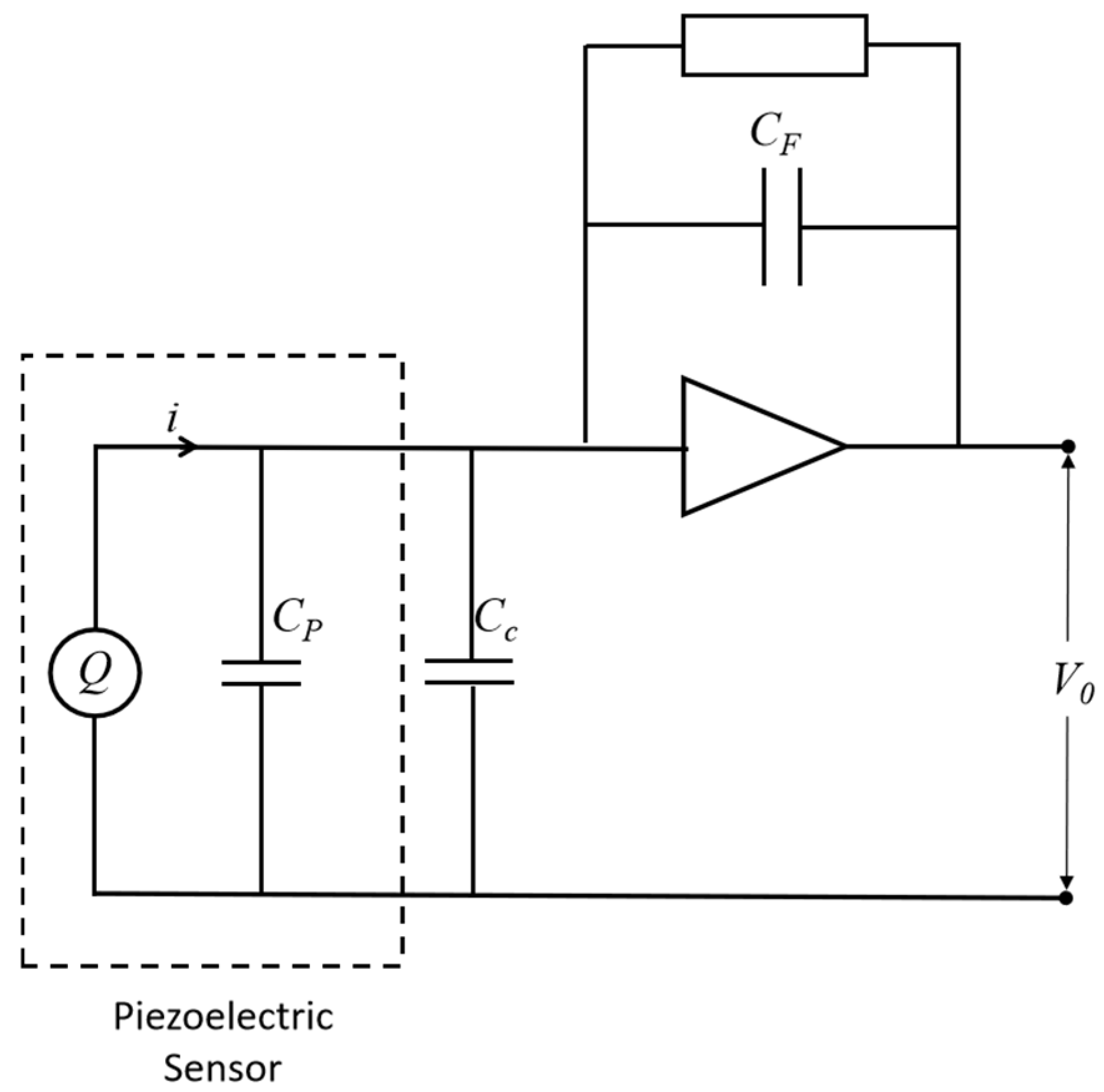
32] developed a similar shear lag model for PZT actuators, sensor modeling differs fundamentally in three aspects. First, sensors rely on the direct piezoelectric effect, unlike the converse effect governing actuators. Second, while actuator studies focus on interfacial shear stress induced by electrical excitation, sensor research aims to ensure the output signal faithfully reflects the host structural response for health assessment. When utilized as a sensor, the initial stress on the polarized surface of the PZT is either zero or a constant. Additionally, the PZT possesses the capability to deform freely along the direction of the electrode surface, thereby resulting in a “mechanically free” mechanical boundary condition. Furthermore, when employed as a sensor, the PZT is typically interfaced with a charge amplifier (as shown in
Figure 1), which effectively eliminates the influence of cable capacitance and variations in the sensor’s intrinsic capacitance on measurement sensitivity, while also providing superior immunity to electromagnetic interference. Under this configuration, the negative feedback mechanism of the operational amplifier maintains a virtual ground at its input terminal, thereby clamping the voltage across the piezoelectric element to an approximate zero value. This constant-electric-field boundary condition corresponds rigorously, in thermodynamic terms, to the independent variable definition of the second-type piezoelectric constitutive equations. Consequently, the second-type formulation should be adopted for modeling purposes [
33].
where
D denotes the electric displacement vector, and
σ is the stress vector.
stands for the electric field strength vector.
ε represents the strain vector, and
sE refers to the elastic compliance at constant electric field, while
eσ denotes dielectric permittivity at constant stress. Additionally,
dd and
dc are the piezoelectric constant matrices, where the superscripts
d and
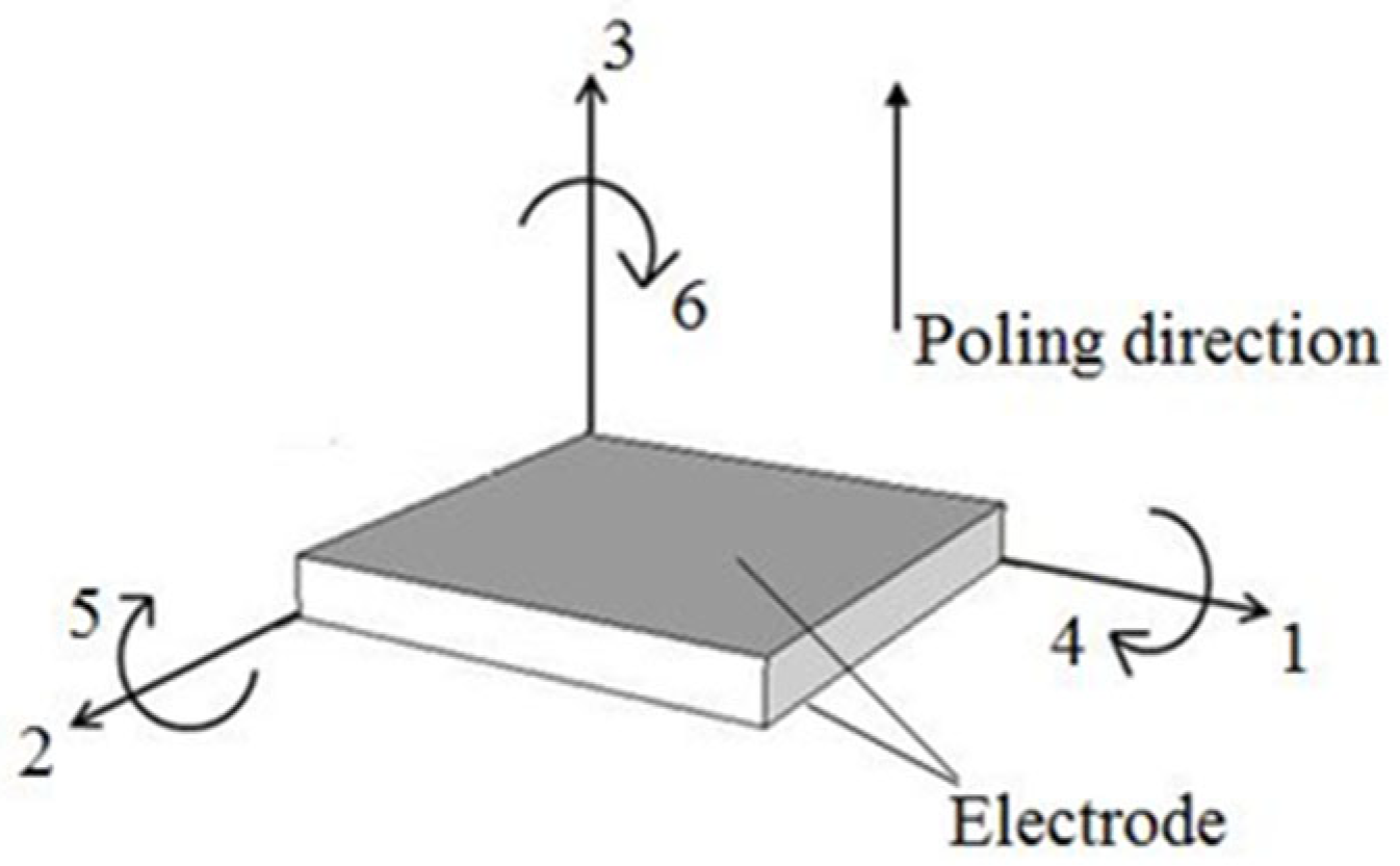
c are employed to distinguish between the positive and negative piezoelectric effects. The computational model of the PZT is illustrated in
Figure 2, where indices 1–6 denote the standard mechanical degrees of freedom
For the bonded PZT sensor, the polarization direction is defined as the three-direction. Given that only the vibration along the one-direction is considered in the dynamic strain transfer analysis, the piezoelectric equations can be simplified as follows:
As a result, the independent variable
is approximately zero. Under such conditions, the charge on the polarized surface of the PZT can be expressed as:
The output voltage of the sensor is:
where
CF denotes the capacitance of the charge amplifier. Assuming that
x is defined as the coordinate along the one-direction (i.e., the lengthwise direction of the sensor), the PZT is configured as a strip-shaped element. Neglecting the influence of Poisson’s ratio in the width direction, with the length and width of the PZT denoted as
lp and
bp, respectively, the output voltage of the sensor can be expressed as:
In the formula, the piezoelectric constant d31 and elastic coefficient s11 of the PZT are constants, and the output voltage of the PZT is proportional to the cumulative strain. Therefore, this study will investigate the variation characteristics of the strain transfer between the host structure and the PZT sensor.
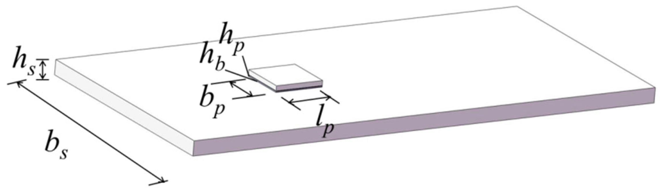
The PZT sensor is bonded to the structural surface via an adhesive layer, and the mechanical model of its coupling system can be simplified to a layered shear strain transfer model consisting of the PZT, adhesive layer, and host structure, as illustrated in
Figure 3.
To establish the mathematical model of the sensor system, the following fundamental assumptions are proposed, which are consistent with the mechanical characteristics of the coupling system and ensure the rationality and solvability of subsequent derivations:
- (1)
The length-to-width ratio of the sensor is greater than or equal to 3, and only the tensile strain of the PZT sheet along the
x-direction (i.e., the longitudinal direction of the sensor) is considered. In general, two-dimensional strain transfer is often approximated as two independent and uncoupled one-dimensional strain transfers. The Poisson’s ratio of piezoelectric ceramics typically ranges from 0.3 to 0.4. Reference [
33] analyzed the effect of Poisson’s ratio on the PZT sensor, demonstrating that when the length-to-width ratio exceeds 3, the influence of the transverse direction on the output voltage of the PZT sensor is less than 10%. In this case, it can be assumed that only the vibration in the longitudinal direction needs to be considered. Furthermore, in general, for piezoelectric ceramic patches, the PZT sensing length is negligible relative to the bending curvature radius, rendering the local strain effectively uniaxial. Therefore, this assumption remains valid even when the patch is bonded to a beam subjected to bending.
- (2)
The PZT material is assumed to be transversely isotropic. When stretched along the longitudinal direction with the width held constant, the stress distribution along the transverse direction is uniform. This assumption is also adopted in classical models in References [
29,
33].
- (3)
During the fabrication of the sensor, the adhesive layer is ideally assumed to be uniformly applied. The shear stress at the interface between the PZT sheet and the adhesive layer is uniformly distributed along the width direction of the PZT sheet, simplifying the interfacial force analysis.
- (4)
Under normal operating strain levels, the elastic deformation of the adhesive layer remains well below the thresholds for interfacial debonding or plastic slip. Therefore, interfaces between the adhesive layer and the PZT, as well as between the adhesive layer and the host structure, are assumed to be perfectly bonded without relative slip. Strain transfer between the host structure and the PZT sensor is entirely achieved through the shear stress of the adhesive layer.
- (5)
To obtain closed-form solutions and clearly elucidate the mechanism of modal coupling, damping effects are neglected in this study. Consequently, the validity of the undamped model is inherently frequency-dependent. In off-resonance regimes, where system dynamics are governed primarily by stiffness or inertia, the discrepancy between undamped predictions and true damped responses remains negligible. However, in the vicinity of resonance, this discrepancy escalates dramatically as the excitation frequency approaches the natural frequencies. Therefore, the near-resonance results presented herein cannot predict the finite peak amplitudes or phase lags observed in experiments. Instead, they should be interpreted strictly as qualitative indicators of dynamic trends and stability boundaries, rather than exact quantitative predictions.
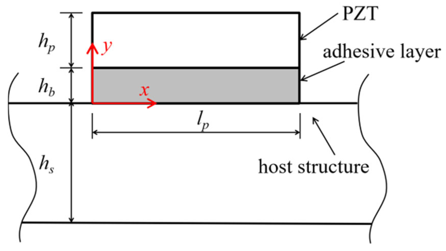
The cross-sectional view of the calculation is shown in
Figure 4. Among them,
hp,
hb and
hs are the thicknesses of the PZT, adhesive layer, and host structure, respectively, and
lp is the length of the PZT along the
x-direction.
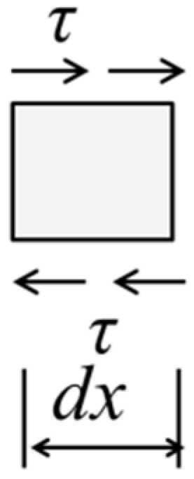
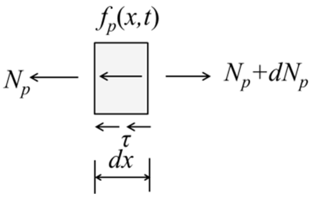
The microelements of the PZT, adhesive layer, and host structure are taken as the analysis objects. For the microelement structure of the PZT sheet, the calculation diagram is shown in
Figure 5.
Np denotes the axial stress acting along the
x-direction,
fP(x,t) represents the inertial force in the
x-direction, and
τ(
x,
t) denotes the shear stress at the interface between the PZT sheet and the adhesive layer. Based on the force balance principle along the
x-direction, the following equation can be derived:
where
up denotes the displacement along the
x-direction,
ρp represents the density of the PZT sensor,
Ep is the elastic modulus of the PZT sensor, and
bp denotes the width of the PZT sensor. Substituting the above expressions into Equation (6) yields the following equation:
Given that the shear wavelength is significantly larger than the adhesive layer thickness, with a representative epoxy resin layer of 0.1 mm thickness, 0.3 GPa shear modulus, and 900 kg/m
3 density yielding a shear wavelength of 1.92 mm at 300 kHz (19.2 times the layer thickness), the inertial force is neglected as validated in Reference [
32], and the adhesive layer functions solely as a medium for shear force transfer. Specifically, the deformation of the host structure is transmitted to the surface of the PZT in the form of shear strain through the adhesive layer. Taking the microelement of the adhesive layer as the analysis object, its force analysis is illustrated in
Figure 6.
Neglecting the influence of Poisson’s ratio of the adhesive layer, the shear stress within the adhesive layer can be expressed as:
where
Gb denotes the shear modulus of the adhesive layer,
γ(
x,
t) represents the shear strain within the adhesive layer, and
us(
x,
t) stands for the displacement of the host structure along the
x-direction.
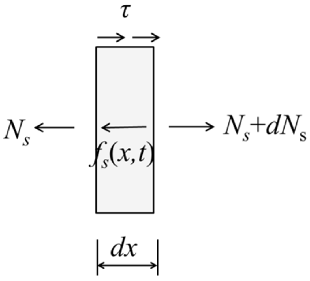
Taking the microelement structure of the host structure as the analysis object, the force analysis is shown in
Figure 7. From the force balance in the
x-direction, we can get:
where
and
Substituting Equation (13) and Equation (14) into Equation (12), we get:
where
ρs denotes the density of the host structure. The boundary conditions for the derived equations are defined as follows: the edges of the PZT sheet are in a free state, while the tensile strain at both ends of the beam structure is maintained at
ε0. Specifically:
When only the steady-state response of the structure is considered, the motions of both the host structure and the PZT sheet along the
x-direction are assumed to be steady harmonic vibrations.
where
Up and
Us are the mode coordinates of the displacement of the PZT and the host structure, respectively. Substituting Equation (17) into Equations (9) and (15), we get:
Equation (19) indicates that
Up and
Us constitute a system of coupled differential equations. To obtain the general solution of this system, decoupling is required. Specifically, Equation (19) is first reformulated in matrix form, and then a transformation matrix is constructed using eigenvalues and eigenvectors to eliminate the coupling terms between the variables. The matrix form of Equation (18) is given as follows:
where
Then the eigenvalues and eigenvectors of matrix
A are calculated, where the eigenvalue
λ is expressed as:
where
T = tr(
A) is the trace of matrix
A, and
D = det (
A) is its determinant. Through calculation, it can be shown that the discriminant
T2 −4
D is strictly positive. Therefore, the eigenvalues
λ1 and
λ2 are always real.
The eigenvectors are
ξ = [
ξ1 ξ2], where
ξ1 = [
ξ11 ξ12]
T and
ξ2 = [
ξ21 ξ22]
T, and Matrix
A can be expressed in terms of its eigenvalues and eigenvectors as:
Substituting into Equation (19), and letting
we can get:
Since
λ is a diagonal matrix,
Up and
Us in Equation (26) are decoupled, allowing the general solution for
F to be obtained. The general solution for
F can be expressed as:
where
and
Then the general solution of
Y is calculated as
Substituting Equation (30) into Equation (21), we can get
Up and
Us, respectively, as:
Then the strain distributions of the PZT and the host structure along the
x-direction are:
Substituting the boundary conditions specified in Equation (16) into the aforementioned expressions, a system of linear equations can be derived as follows:
Solving the linear system of equations shown in Equation (33), the coefficients C1 to C4 can be obtained.
As can be seen from the derivation, once the sensor’s fabrication and material parameters are specified by the initial conditions, matrix A becomes known, enabling the calculation of its eigenvalues and eigenvectors. Subsequently, the constants C1–C4 can be determined based on the boundary conditions, thereby yielding the expressions for Up, Us, the sensor strain εp, and the host structure strain εs. The entire computational procedure can be implemented in MATLAB R2016b.
The presence of the adhesive layer between the PZT sensor and the host structure induces a shear lag effect during strain transfer between the two components. Specifically, the strain of the host structure is not fully transferred to the PZT, and strain transmission between the host structure and the PZT surface is entirely mediated by the shear stress of the adhesive layer. To quantify the shear strain transfer effect between the host structure and the sensor, the distribution of the strain ratio between the PZT sensor and the host structure along the
x-axis is defined as
k(
x) [
12,
18,
20,
21], as given in Equation (35). Notably, all coefficients
C1–
C4 include the term
ε0, rendering
k(
x) independent of
ε0. A
k(
x) value closer to 1 indicates a higher degree of consistency between the sensor strain and the host structure strain.
In addition, the strain ratio between the sensor and the host structure is defined as shown in Equation (35). Specifically,
K represents the average strain ratio along the sensor length, which also corresponds to the actual effective length of the PZT sensor. Owing to the shear lag effect induced by the adhesive layer, the strain of the PZT along the
x-direction deviates from the true strain of the host structure. Therefore, the strain ratio is employed to quantify the strain transfer performance between the sensor and the host structure. A strain ratio closer to 1 indicates a more complete transfer of the host structure’s strain to the sensor.
3. Numerical Simulation
ANSYS has been widely employed to simulate stress wave transmission and reception in piezoelectric materials [
3,
38]. In this study, a 2D finite element (FE) model is developed using ANSYS 2022R1 to validate the aforementioned dynamic strain transfer analysis of the PZT. Unlike the theoretical model, the two-dimensional model does not impose constraints on the strain distribution through the thickness and accounts for the inertial forces of all three constituent materials. The one-dimensional analytical model is employed to elucidate the physical relationships among parameters and provide closed-form solutions, while the two-dimensional finite element model serves to validate the analytical results and capture the two-dimensional effects neglected by the simplifying assumptions.
The schematic diagram of the 2D model for the PZT–adhesive layer–host structure system is illustrated in
Figure 8. A harmonic excitation of
Fsin (2
πft) is applied at both ends of the host structure (where
x = 0.055). The geometric dimensions and physical parameters of the PZT, adhesive layer, and host structure are summarized in
Table 1.
As depicted in the figure, the configuration constitutes a symmetric structure subjected to symmetric loading; therefore, only half of the model (along the y-axis) is analyzed for computational efficiency. Displacement constraints are imposed as follows: the x-directional displacement is restrained for nodes at x = 0, which corresponds to the zero axial displacement at the midpoint due to the geometric symmetry of the PZT along the x-axis in the analytical model. Meanwhile, the y-directional displacement is constrained for nodes at y = 0; this constraint serves solely to eliminate rigid-body motion while preserving the free-boundary condition at both ends of the PZT, thus remaining fully consistent with the theoretical formulation.
The interfaces between the PZT and the adhesive layer, as well as between the adhesive layer and the host structure, are assumed to be perfectly bonded. Since this analysis focuses primarily on the mechanical behavior of the three constituent materials without considering electromechanical coupling, the finite element model was developed using the ANSYS PLANE182 element, which is a four-node quadrilateral structural solid element with linear displacement shape functions. The analysis was conducted under the plane stress assumption (KEYOPT(3) = 0, default). Quadrilateral elements are used to mesh the PZT, adhesive layer, and host structure, with a uniform element size of 0.025 mm.
Modal analysis was first performed on the coupled structure, and the first three natural frequencies were obtained as 167.191 kHz, 176.620 kHz, and 185.634 kHz. The first three mode shapes are illustrated in
Figure 9. It can be observed that the first mode is dominated by tensile deformation, the second mode primarily exhibits bending deformation, and the third mode involves a combination of tension and bending. The close proximity of the first three natural frequencies (with a relative difference of approximately 5%) suggests modal coupling among these modes. However, quantitative evaluation reveals that the bending-induced axial–flexural coupling generalized stiffness amounts to only 1.89% of the primary axial stiffness. Given the negligible magnitude of this coupling term, neglecting modal coupling is considered reasonable and reliable within the required accuracy of the present analysis. Accordingly, subsequent dynamic analyses were conducted at excitation frequencies below the first natural frequency to ensure consistency with the theoretical assumptions of this study.
Subsequently, a transient analysis was performed. A harmonic stress was applied to 0.5sin(2πft) the nodes at one end of the host structure (x = 0.0055 m). The analyses were conducted at excitation frequencies of 50 kHz, 100 kHz, and 150 kHz. For each case, the simulation comprised 300 load steps with a time step size of 0.1 μs. The Newton–Raphson iterative scheme was employed with force and displacement convergence tolerances set to 0.5% of the reference norms. Automatic time stepping (AUTOTS, ON) was activated to ensure robust convergence during phases of strong geometric nonlinearity. Upon completion of the simulations, nodal data were extracted from both adhesive interfaces to investigate the variation of the strain ratio along the longitudinal direction under different excitation frequencies.
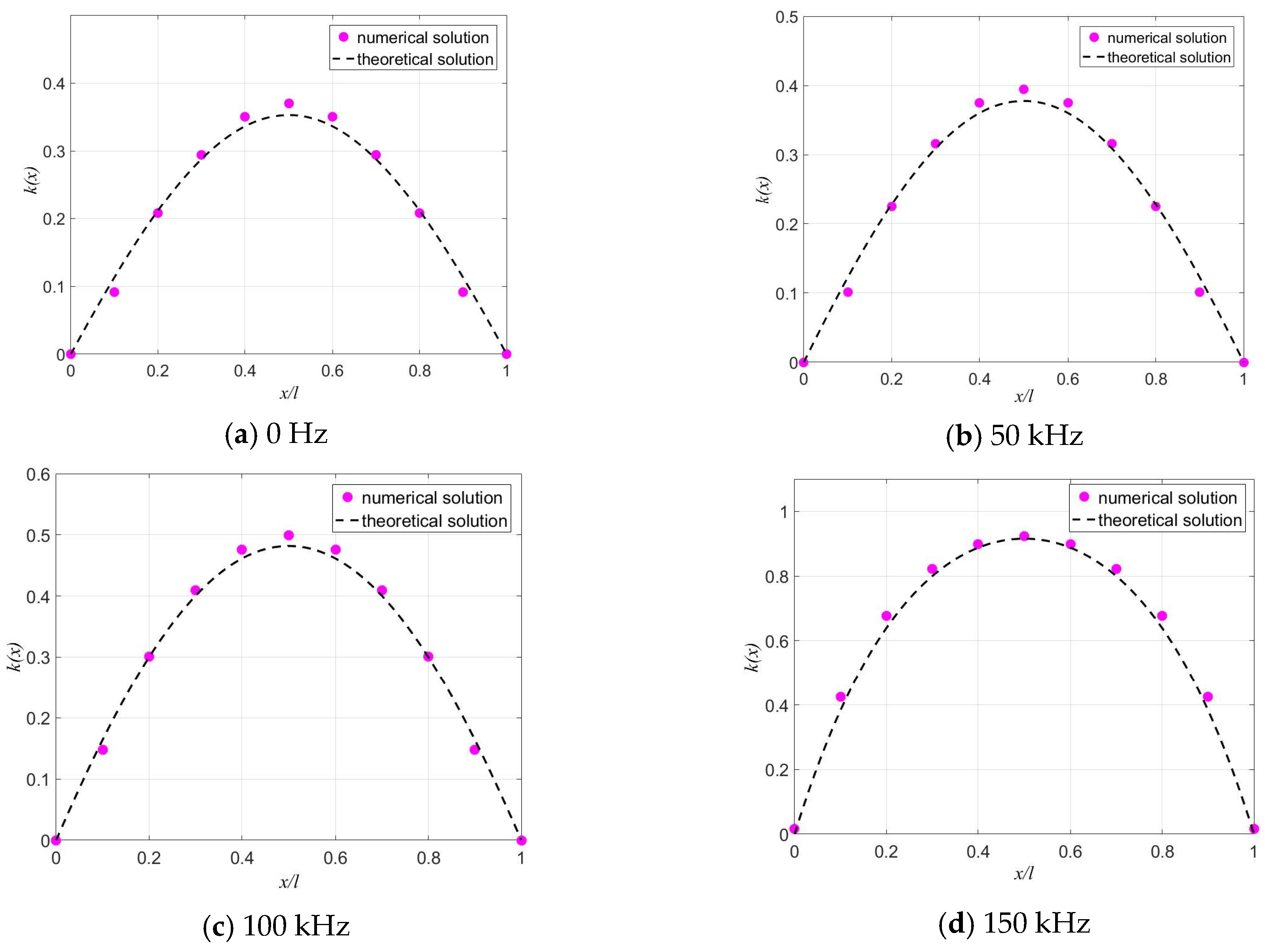
The numerical solution from ANSYS is compared with the theoretical solution from MATLAB to validate the proposed model. As shown in
Figure 10, the distributions of the strain ratio
k(
x) in Equation (34) are compared at 0 Hz, 50 kHz, 100 kHz, and 150 kHz. The maximum error rates in
Figure 10a–d are 4.85%, 4.55%, 3.53%, and 9.07%, respectively. It can be observed that the theoretical results agree well with the numerical results, which verifies the validity of the proposed theoretical model. In addition, owing to the shear lag effect caused by the adhesive layer, the distribution of the strain ratio
k(
x) varies with increasing frequency within a certain frequency range. Therefore, dynamic excitation on the structure further exacerbates the shear lag effect of the adhesive layer.
4. Parameter Analysis
In this section, the effects of structural parameters on the dynamic strain transfer characteristics of the PZT–adhesive layer–host structure system are analyzed. In the following parametric study, each parameter is varied individually while all remaining parameters are fixed at their baseline values listed in
Table 1.
4.1. Static Analysis
For the coupled system comprising the host structure, adhesive layer, and surface-bonded sensor, the strain of the host structure would ideally be fully transferred to the sensor under ideal conditions. In this case, the sensor strain equals the host strain, yielding a strain ratio of unity along the entire sensor length. However, due to the shear lag effect in the adhesive layer, the strain distribution in the sensor does not fully match that of the host structure. Nevertheless, the strain ratio between the sensor and the host structure remains constant; therefore, a compensation factor can be applied to correct the measured strain, thereby obtaining a more accurate representation of the true host structure strain.
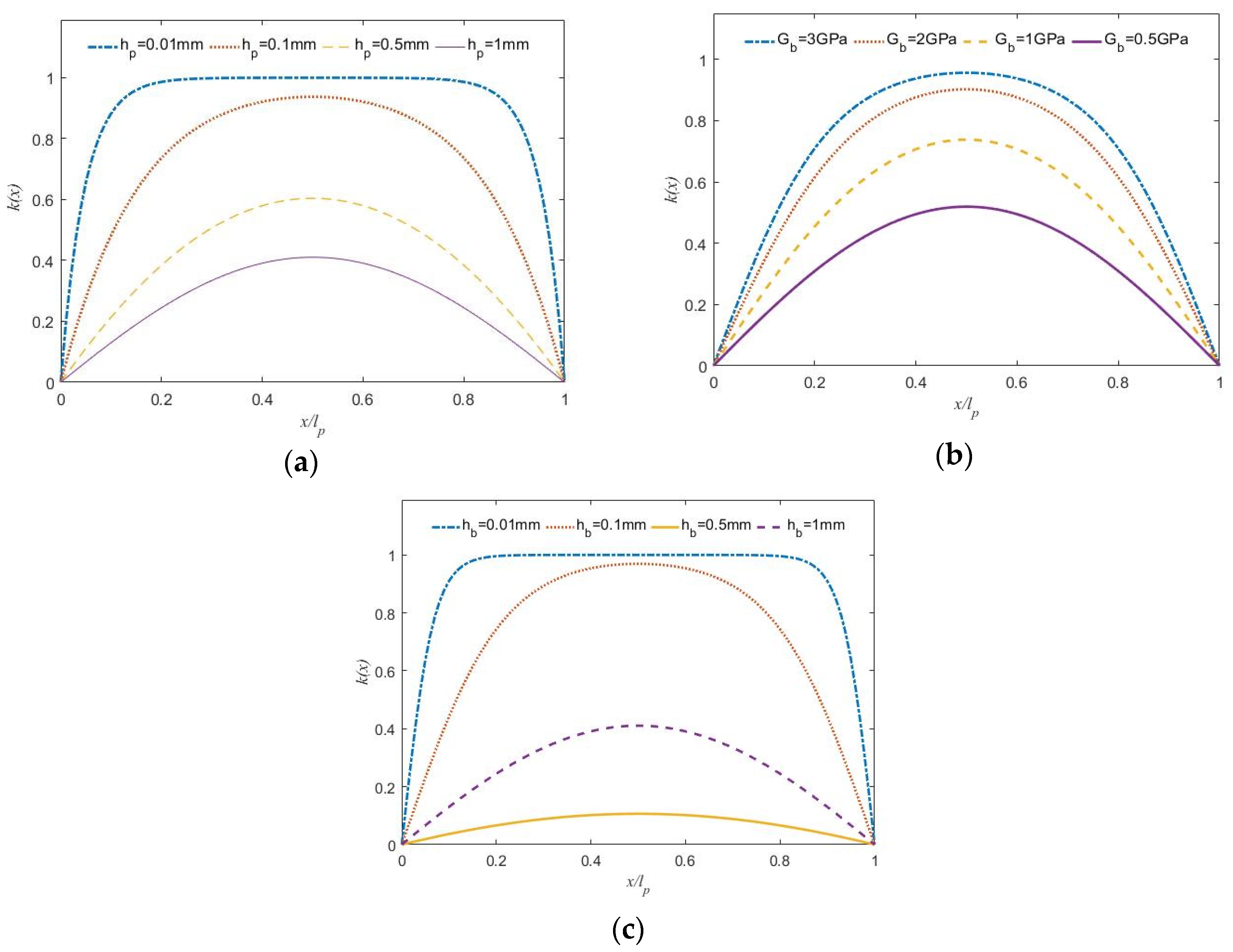
Under static tension conditions, the distributions of the strain ratio between the PZT and the host structure along the tensile direction are analyzed with different PZT sheet thicknesses, adhesive layer shear moduli, and adhesive layer thicknesses, as presented in
Figure 11.
The results demonstrate that decreasing the thicknesses of both the PZT and the adhesive layer, while increasing the adhesive shear modulus, significantly improves the static strain transfer performance of the sensor.
4.2. Influence of Measured Signals Frequency
PZT sensors are multi-purpose devices, and the frequency of the measured signals varies with different monitoring targets. When subjected to measured signals of different frequencies, the sensor exhibits distinct strain transfer characteristics. Accordingly, it is essential to evaluate the effect of signal frequency.
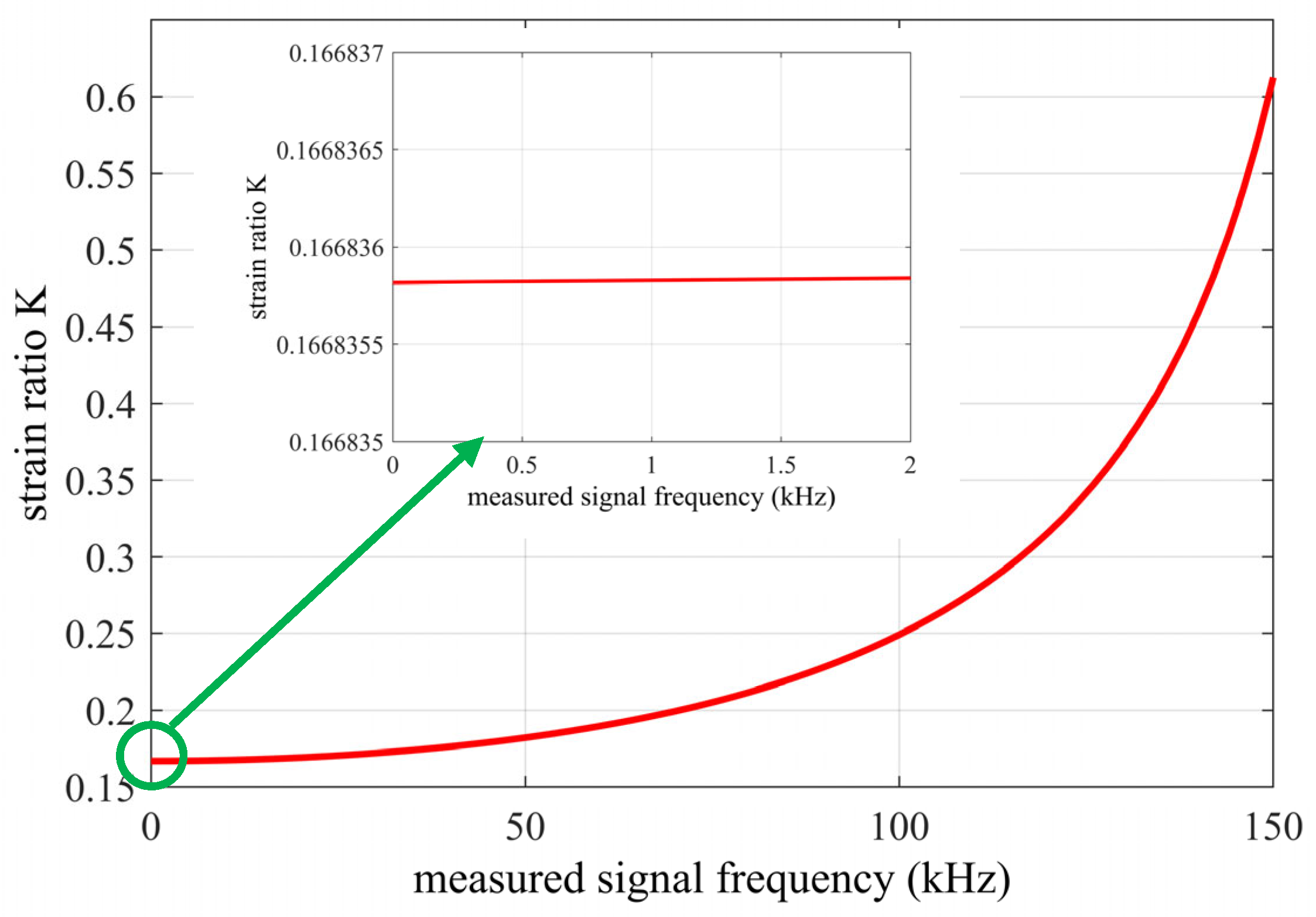
The variation of the strain ratio between the PZT sensor and the host structure over 0–150 kHz is analyzed in
Figure 12. The strain ratio increases with frequency, indicating that bonded PZT sensors are more sensitive to high-frequency strain signals. To examine the transfer characteristics within the global vibration range of civil engineering structures (typically a few Hz to several hundred Hz),
Figure 12 illustrates the strain ratio in the 0–2 kHz range. The ratio rises only from 0.16684 at 0 Hz to 0.16686 at 2 kHz (a mere 0.002% increase), allowing it to be approximated as constant in this low-frequency band. Parametric analysis confirms that while the strain ratio remains stable at low frequencies, it increases notably at high frequencies, necessitating frequency-dependent correction. From a system dynamics perspective, this behavior is analogous to the phase deviation mechanism in vibration isolation systems [
42], highlighting that dynamic coupling between the sensor and host structure fundamentally dictates measurement fidelity under varying excitation frequencies. Consequently, for global vibration monitoring, frequency dependence can be neglected and a constant calibration factor suffices to retrieve the true strain.
Conversely, for local damage assessment using high-frequency stress waves (tens to hundreds of kHz), such as active elastic waves or acoustic emission, the calibration factor must be frequency-dependent. Therefore, a practical frequency-dependent calibration procedure can be implemented based on the predetermined strain ratio function K(ω) (where ω = 2πf) derived from the proposed theoretical or numerical model. In practice, once the signal frequency is identified via spectral analysis, the corresponding correction factor 1/K(ω)is directly applied to the measured amplitude. This accurately recovers the true dynamic strain of the host structure and compensates for high-frequency strain transfer distortion.
4.3. Influence of PZT Thickness
Given the widespread use of PZT patches with varying thicknesses in sensor fabrication, this study examines the effect of PZT thickness on strain transfer performance.
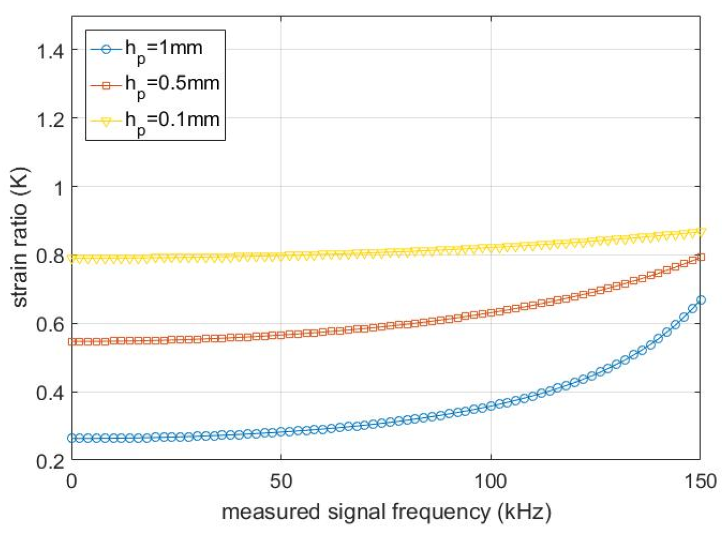
Figure 13 illustrates the strain ratio between the PZT and host structure with measured signal frequency when the PZT thickness equals 1 mm, 0.5 mm, and 0.1 mm. As shown, the PZT patch with a thickness of 0.1 mm exhibits the highest strain ratio, which also remains the most stable across the frequency range. In contrast, the 1 mm thick PZT patch shows the lowest strain ratio and the most pronounced frequency dependence.
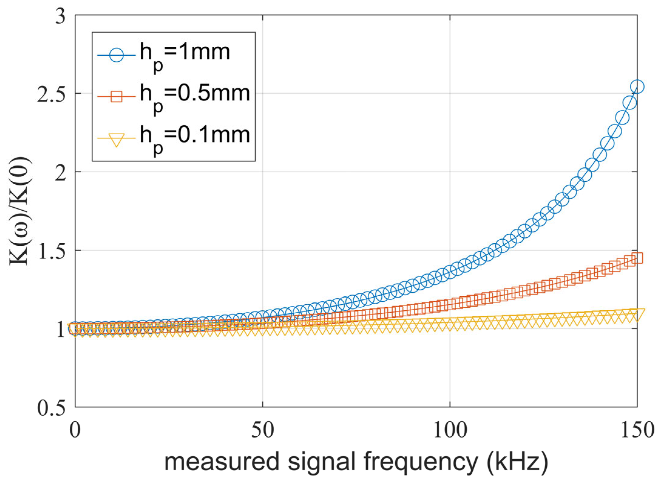
The sensitivity of strain transfer to frequency is evaluated by identifying the frequency range over which the strain ratio increases by 10% from its static value.
Figure 14 illustrates the variation of
K(
ω)/
K(0) with frequency. The strain ratio increment remains within 10% for PZT thicknesses of 1 mm, 0.5 mm, and 0.1 mm over frequency ranges of 0–59 kHz, 0–83 kHz, and 0–152 kHz, respectively. Within this 10% threshold, the influence of dynamic strain transfer is considered negligible, thereby eliminating the need for compensation in strain measurements. Evidently, a thinner PZT patch yields a broader frequency range within which compensation can be safely neglected.
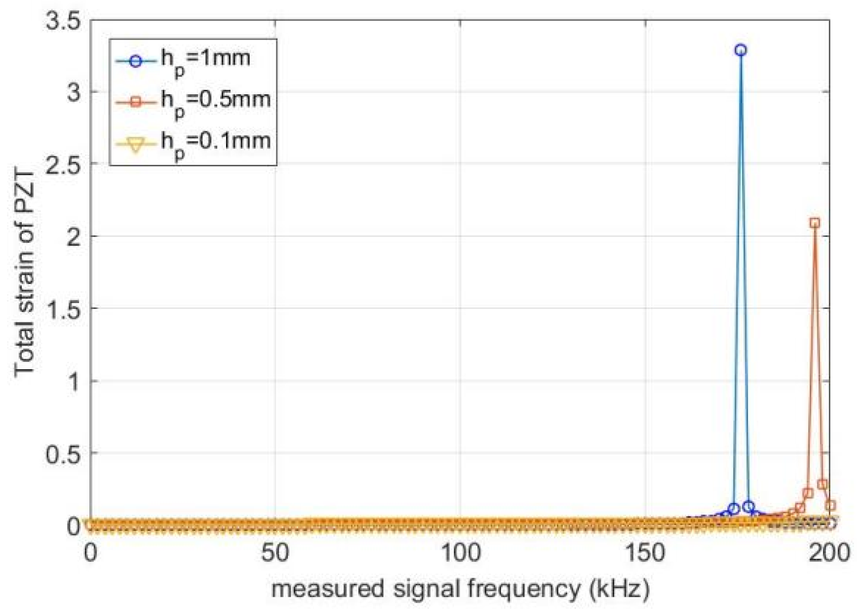
Figure 15 illustrates the total strain of the PZT along the sensor length with frequency when the PZT thickness equals 1 mm, 0.5 mm and 0.1 mm respectively. The 0.1 mm thick PZT exhibits the highest first-order frequency in the lengthwise direction, while the 1 mm thick PZT has the lowest. Therefore, thinner PZT sheets result in a higher natural frequency of the sensor system in the lengthwise direction, making thinner PZT sheets preferable for fabricating bonded sensors.
The above analysis demonstrates that PZT thickness significantly influences strain transfer characteristics. Specifically, a thinner PZT patch yields a higher strain ratio with milder frequency dependence, extends the frequency range within which strain compensation is negligible, and increases the first-order natural frequency of the sensor system. Therefore, thinner PZT sheets reduce the influence of the driving frequency on the sensor’s dynamic strain transfer. Consequently, it is strongly recommended to select the thinnest feasible PZT patches when fabricating surface-bonded strain sensors.
4.4. Influence of Adhesive Layer Shear Modulus
Given that the adhesive shear lag effect induces significant variations in dynamic strain transfer across different bonding materials, this study systematically evaluates how adhesive properties govern the sensor’s dynamic response. Silicone rubber, polyurethane, and epoxy resin are commonly employed as bonding agents for PZT sensors, with representative shear moduli of approximately 0.3 MPa, 200 MPa, and 1000 MPa, respectively. Taking these three shear moduli as examples, this section illustrates the effect of adhesive material properties on the dynamic strain transfer characteristics of PZT sensors.
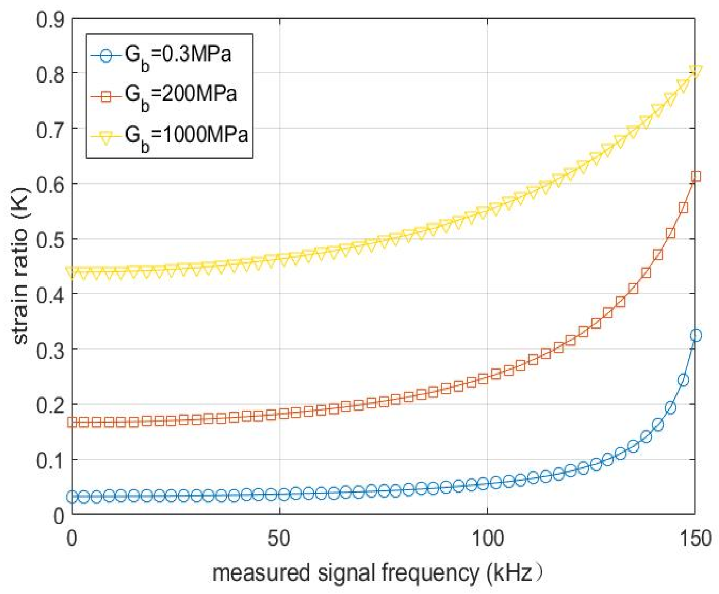
Figure 16 shows the variation in the strain ratio between the PZT and the host structure with frequency for different adhesive shear moduli. The adhesive with a shear modulus of 1000 MPa exhibits the highest strain ratio and the most stable frequency response, whereas the adhesive with a shear modulus of 0.3 MPa yields the lowest strain ratio and the most prominent frequency dependence. The monotonic increase in strain ratio with increasing shear modulus further confirms that a higher shear modulus leads to superior strain transfer efficiency.
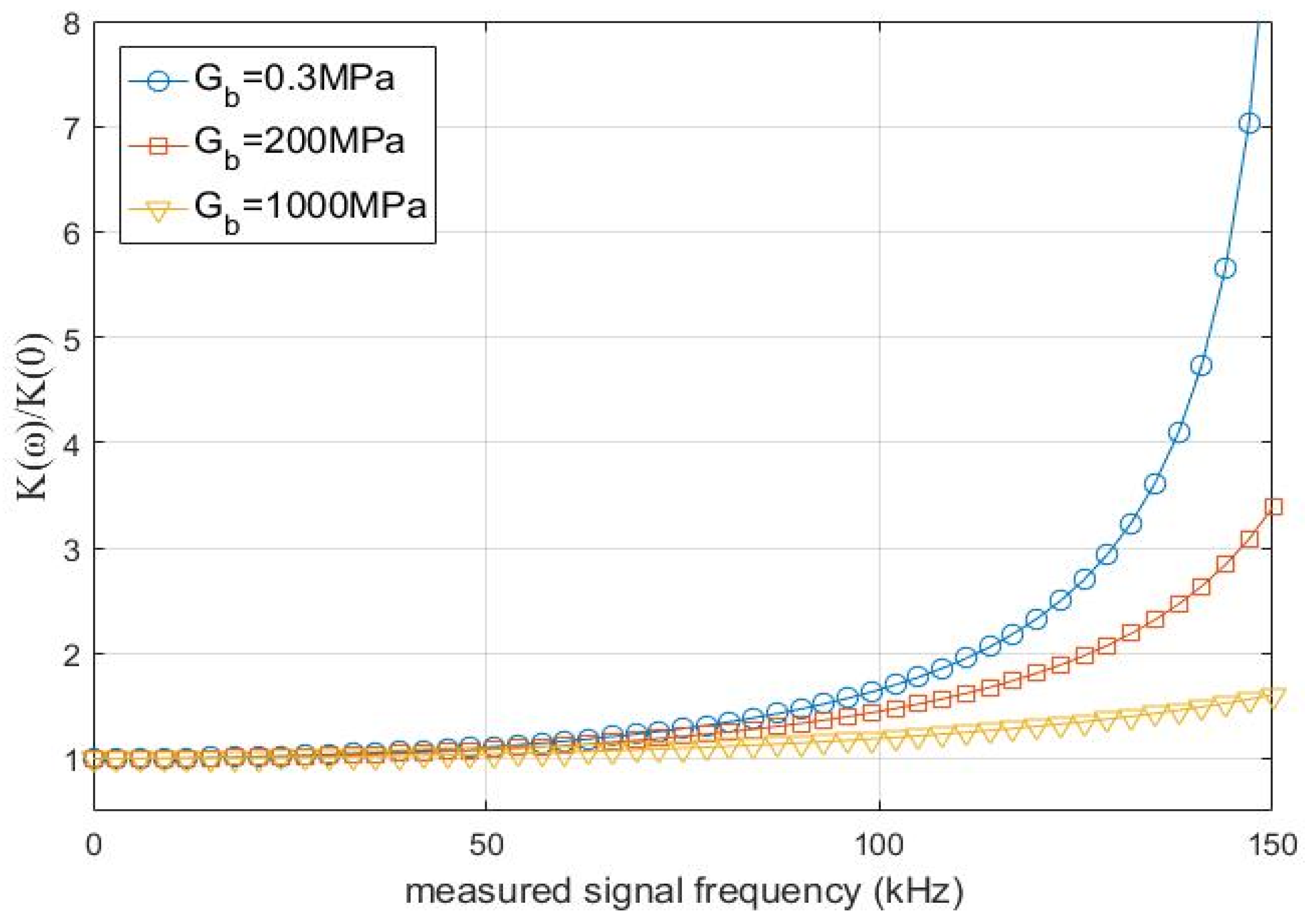
Figure 17 illustrates the variation of K(
ω)/K(0) with frequency. The strain ratio increment remains within 10% over frequency ranges of 0–48 kHz, 0–54 kHz, and 0–76 kHz for adhesive shear moduli of 0.3 MPa, 200 MPa, and 1000 MPa, respectively. Evidently, a higher adhesive shear modulus yields a broader frequency range within which strain compensation can be safely neglected.
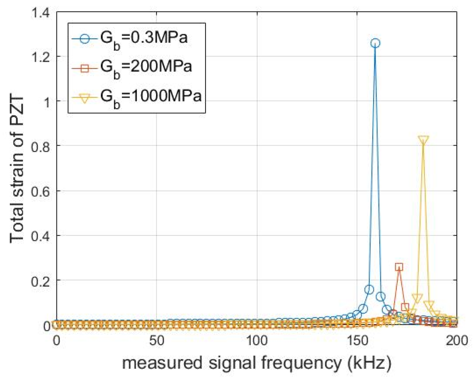
Figure 18 illustrates the variation in PZT strain amplitude along the length direction with frequency for different adhesive shear moduli. The first-order frequency of the PZT in the lengthwise direction is the highest for the adhesive shear modulus of 1000 MPa and the lowest for 0.3 MPa, meaning that a higher adhesive shear modulus increases the natural frequency of the PZT along the length direction.
Based on the above analysis results, the properties of the adhesive layer have a significant impact on the strain transfer behavior of the sensor. A higher adhesive shear modulus yields a larger strain ratio with a flatter frequency response, thereby extending the frequency range within which strain compensation can be safely neglected and increasing the first-order natural frequency of the PZT. Consequently, adhesives with high shear moduli should be prioritized in the fabrication of bonded PZT sensors. Epoxy resin and similar high-modulus bonding agents are particularly well suited for applications where dynamic strain transfer fidelity is critical.
4.5. Influence of Adhesive Layer Thickness
The thickness of the adhesive has a significant impact on the strain transfer properties of the bonded PZT sensor, and it is necessary to analyze the influence of different adhesive layer thicknesses on the dynamic strain transfer characteristics.
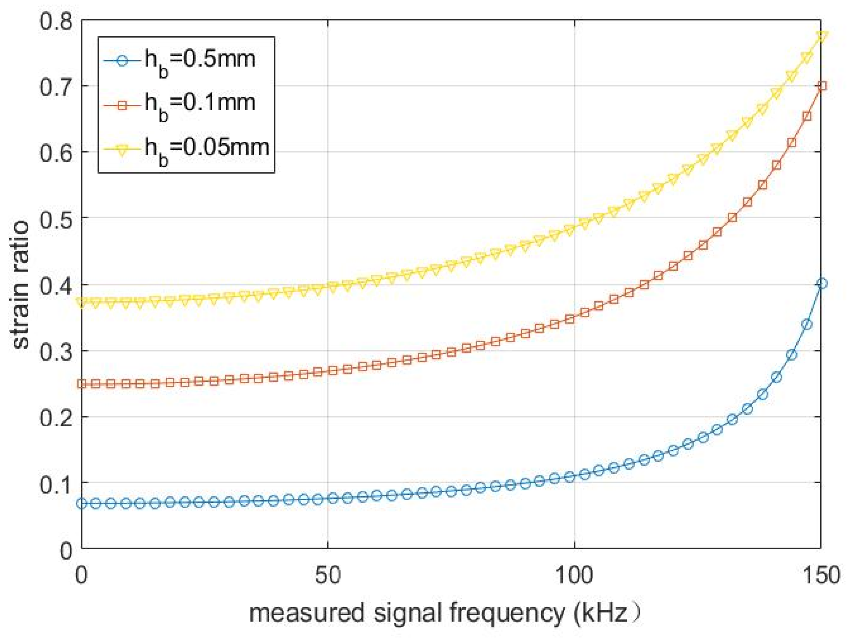
Figure 19 presents the variation of the strain ratio between PZT and the host structure with frequency for adhesive layer thicknesses of 0.5 mm, 0.1 mm, and 0.05 mm. As can be observed from the figure, the strain ratio reaches its maximum value with the flattest frequency response at a thickness of 0.05 mm, whereas it attains its minimum with the steepest frequency dependence at 0.5 mm. The strain ratio increases as the adhesive layer thickness decreases, indicating that a thinner adhesive layer yields higher strain transfer efficiency.
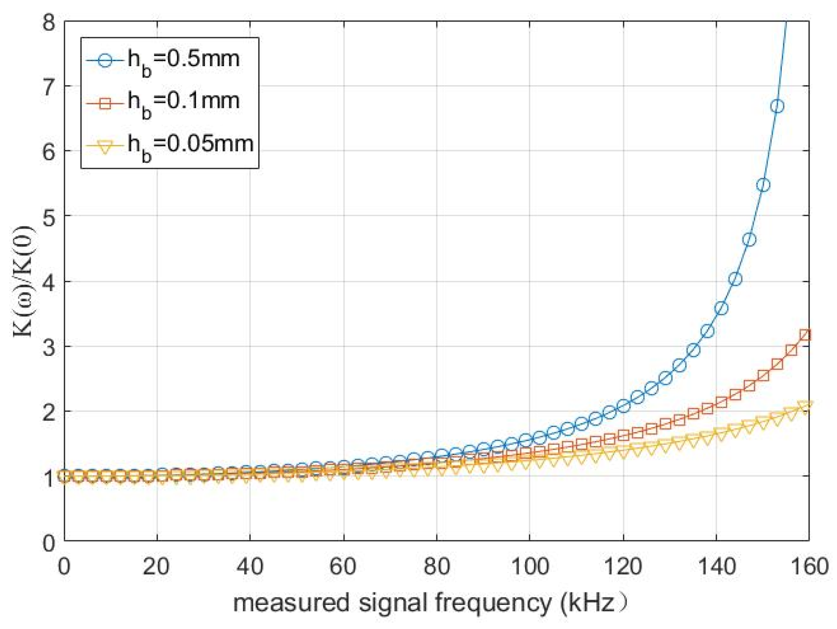
Figure 20 illustrates the variation of K(
ω)/K(0) with frequency for different adhesive layer thicknesses. For adhesive thicknesses of 0.5 mm, 0.1 mm, and 0.05 mm, the strain ratio increment remains within 10% over frequency ranges of 0–50 kHz, 0–59 kHz, and 0–68 kHz, respectively. It is evident that a thinner adhesive layer extends the frequency range within which strain compensation can be safely neglected.
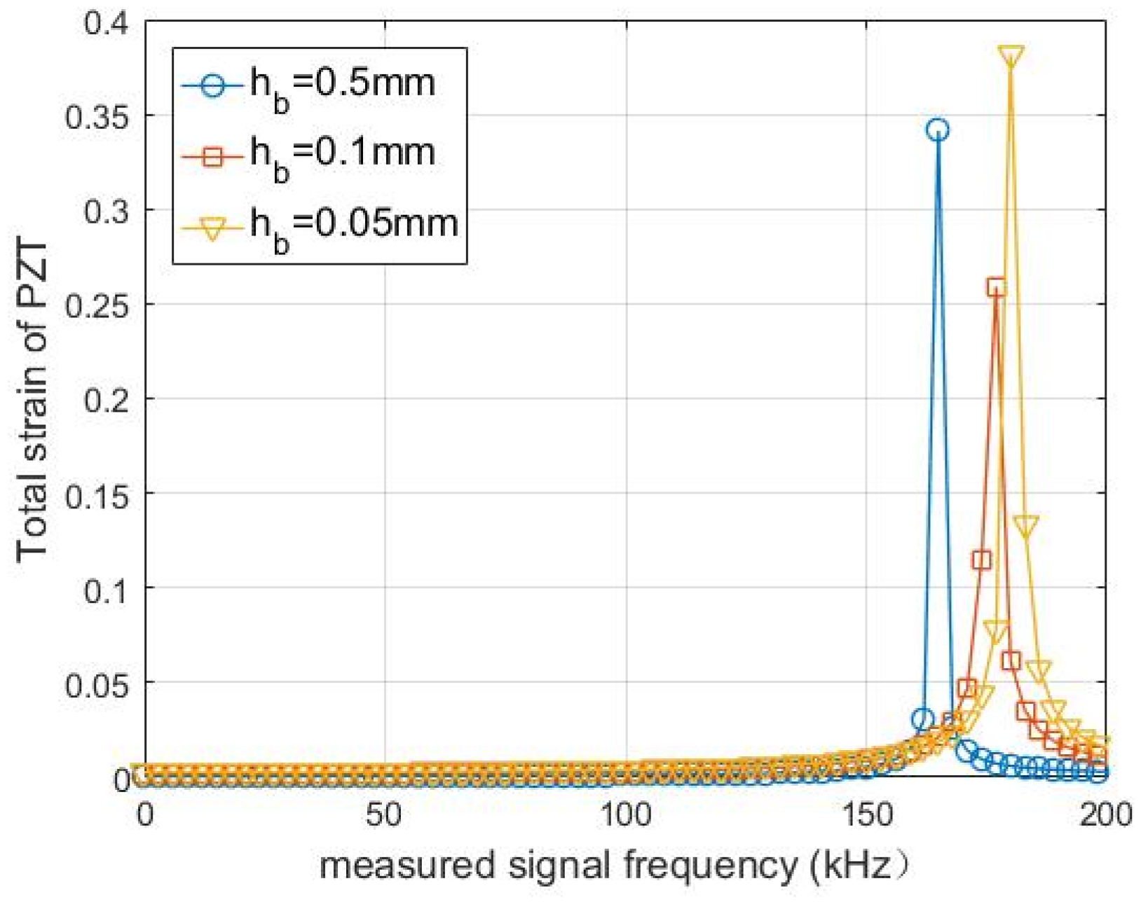
Figure 21 illustrates the variation in total strain of the PZT along the length direction with frequency for different adhesive thicknesses. The sensor system exhibits the highest first-order frequency in the lengthwise direction at 0.05 mm, followed by 0.1 mm, and the lowest at 0.5 mm. Thus, a thinner adhesive layer increases the natural frequency of the bonded PZT sensor system in the lengthwise direction.
The above analysis demonstrates that the adhesive layer thickness has a significant impact on the dynamic strain transfer of the bonded PZT sensor system. A thinner adhesive layer yields a higher strain ratio, extends the frequency range within which strain compensation can be safely neglected, and increases the first-order natural frequency of the PZT system. Therefore, during the fabrication of bonded PZT sensors, the adhesive layer thickness should be minimized to achieve higher strain transfer efficiency and mitigate the influence of frequency on the transfer characteristics.
4.6. Influence of Host Structure
For the “PZT–adhesive layer–host structure” system, if the cross-sectional area of the PZT is close to that of the host structure, the influence of the host structure on the dynamic characteristics of the sensor system must be considered. Let
As and
Ap denote the cross-sectional areas of the host structure and PZT direction perpendicular to the polarization direction, respectively.
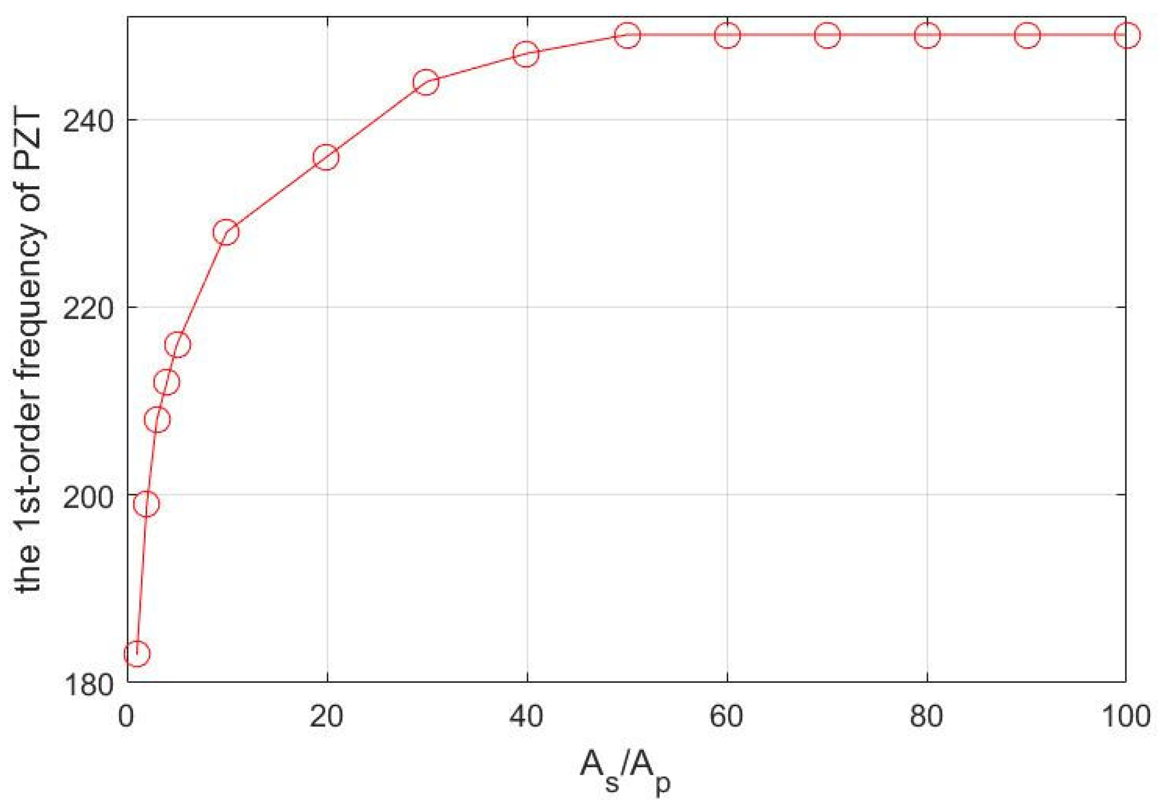
Figure 22 illustrates the variation of the first-order frequency of the PZT with different
As/
Ap ratios. It can be observed that as the
As/
Ap ratio increases, the first-order frequency approaches a constant value. Under this specific condition, when
As/
Ap exceeds 50, the first-order frequency of the PZT approaches 248 kHz and tends to stabilize. For host structures with small cross-sectional areas (i.e., small
As/
Ap), the influence of the host structure on the PZT cannot be ignored; only when
As/
Ap reaches a certain threshold can the influence of the host structure on the PZT’s dynamic characteristics be neglected. This conclusion provides a theoretical basis for simplifying the design of PZT sensors in civil engineering structures, where the host structure usually has a much larger cross-sectional area than the PZT sensor.