Article

A Semi-Analytical and Data-Calibrated Hybrid Model for Predicting Residual Deformation of Shape Memory Alloy Honeycombs

1
School of Civil Engineering, Southeast University, Nanjing 210096, China
2
Qian Xuesen Laboratory of Space Technology, China Academy of Space Technology, Youyi Street No. 104, Haidian, Beijing 100094, China
3
Troops 32382 PLA, Renminxi Street No.45, Weibin District, Xinxiang 453000, China
4
State Key Laboratory of Heavy Oil Processing, China University of Petroleum, Beijing 102249, China
*
Author to whom correspondence should be addressed.
Buildings 2026, 16(12), 2406; https://doi.org/10.3390/buildings16122406
Submission received: 28 April 2026 / Revised: 21 May 2026 / Accepted: 15 June 2026 / Published: 17 June 2026
(This article belongs to the Section Building Structures)

Abstract

Future lunar missions, like the International Lunar Research Station (ILRS), demand single-launch multi-point operations, urgently requiring reusable energy-absorbing structures. Integrating shape memory alloy (SMA) into honeycombs offers a promising solution; however, deformation exceeding the SMA’s recoverable limit induces structural residual deformation, altering the configuration and degrading subsequent energy absorption. To address this, we propose a semi-analytical, data-calibrated hybrid model predicting SMA honeycomb residual deformation. A four-stage linear constitutive model is established capturing superelasticity and martensitic yielding. Cell walls are idealized as equivalent beams. Using layered fiber integration and numerical interpolation, a nonlinear moment–curvature relationship is constructed, enabling rapid structural residual deflection evaluation from material residual strains. Finite element results confirm that initial residual deformation stabilizes the honeycomb into a reusable configuration, governing subsequent plateau stresses. Calibrated by uniaxial test data, the proposed model accurately predicts residual deformation ratios and reusable plateau stresses with errors within 8%. By bridging material-level strain with structural-level deformation, this approach circumvents computationally expensive full-scale simulations and costly experimental trials, providing a highly efficient tool for designing reusable SMA absorbers.

1. Introduction

With the rapid advancement of next-generation deep space exploration and aerospace engineering projects, such as the International Lunar Research Station (ILRS) [1], the Artemis program [2,3], and reusable launch vehicles [4], the demand for lightweight, high specific-energy absorption, and reusable energy-absorbing structures has become increasingly urgent. To balance launch costs and wide-area exploration requirements, the development and optimization of reusable planetary landers have become a critical focus [5]. For instance, to support heavy payloads and extended surface operations, space agencies are actively pursuing high-capacity transportation systems, such as Europe’s proposed large-mass logistic landers [6]. Furthermore, during the forthcoming construction of lunar base infrastructures [7] and broader deep space exploration missions [8], the operational mode of “single-launch multi-point missions” represents an inevitable future trend. Because these complex scenarios require landers to perform continuous, multi-site hopping and endure multiple landing impacts, integrating highly reliable and reusable buffering structures is essential. In addition, recent studies on adaptive landing systems and reusable footpad concepts have further highlighted that future planetary landing systems require not only effective impact mitigation but also structural reusability and robustness under uncertain landing conditions [9,10].
The buffering approach that integrates honeycomb structures with legged landers is currently one of the most prevalent methods for planetary surface landers. At the macroscopic system level, it offers numerous advantages, including high landing stability [11,12], low rebound tendency [13], and a stable, adjustable landing posture [14]. In practical engineering, this buffering mechanism involves the dissipation of kinetic energy through the deformation of honeycomb structures installed in the inner and outer cavities of the landing legs under impact loads. This configuration has been highly successful and validated in numerous extraterrestrial missions, ranging from the historical Apollo lunar module [15] to the recent Tianwen-1 Mars probe [16]. To further enhance crashworthiness, researchers have continually optimized metal honeycomb absorbers specifically for lunar landers [17] and explored advanced bio-inspired hierarchical configurations [18]. Underpinning these engineering applications is the progressive crushing behavior of cellular materials, which has been systematically established through foundational analytical theories on the crushing mechanics of metal honeycombs [19] and multi-cell thin-walled structures [20]. Beyond aerospace engineering, the design of highly reliable energy-absorbing structures remains a universal challenge in broad impact dynamics. These fundamental principles of crashworthiness and large deformation mechanisms have continually driven safety innovations in terrestrial transportation, such as the multi-material synergistic design of high-strength steel guardrails [21] and the structural enhancement of bolted reinforced honeycomb crash cushions [22]. Moreover, porous metallic materials and honeycomb structures have long been recognized as effective energy-absorbing components in spacecraft landing gear, which further supports the engineering relevance of honeycomb-based buffering systems in extraterrestrial landing applications [23].
Shape memory alloys (SMAs), particularly nickel–titanium (NiTi) alloys, have emerged as ideal materials for constructing reusable energy-absorbing structures due to their unique microscopic reversible austenite–martensite phase transformation, which endows the material with excellent deformation recovery capabilities and outstanding hysteretic energy dissipation properties. In recent years, researchers have also explored various alternative material systems to achieve structural reusability, such as metamaterials based on a shape memory polymer (SMP) [24], hyperelastic thermoplastic polyurethane (TPU) thin-walled structures [25], and liquid metals [26]. Recent 4D-printing studies on SMP honeycomb metamaterials have demonstrated promising recoverable energy dissipation, but their mechanical degradation and load-bearing limitations under repeated loading remain non-negligible [27]. By contrast, a NiTi SMA can simultaneously provide strong recoverability, high energy dissipation, and superior structural strength. Therefore, investigations into incorporating an SMA into advanced meso-scale topological configurations, such as honeycomb [28], chiral [29], and architected lattice structures [30,31], have attracted significant attention. Concurrently, integrating programmable kinematics into thin-walled elements has spawned novel reusable structural systems, such as self-stable assembled origami structures [32] and non-Euclidean origami configurations [33], which demonstrate exceptional compressive reusability and energy dissipation.
In particular, aided by additive manufacturing technologies such as laser powder bed fusion and selective laser melting (SLM), recent studies have successfully developed NiTi architected metamaterials with enhanced deformation recovery, damage tolerance, and cyclic functionality. For instance, Michailidis et al. [34] and Watkins et al. [35,36] investigated the reusable compressive behavior of SMA honeycombs. Furthermore, Xiong et al. [37,38] and other researchers [39,40] fabricated honeycomb and lattice structures featuring the shape memory effect (SME) using modified SLM-based technologies. More recent work has shown that the mechanical response of additively manufactured NiTi cellular structures can be significantly improved through architectural design, including TPMS lattices [41], hybrid spiral lattices [42], and architected structures with enhanced fatigue resistance [43]. These advances further demonstrate the great potential of NiTi-based cellular materials for reusable impact mitigation under multiple loading events.
However, the recoverable deformation of SMA is intrinsically limited, as observed in macroscopic structural components [44]. Comprehensive constitutive modeling further confirms that any local deformation exceeding this reversible threshold inevitably results in residual strain owing to transformation-induced plasticity [45,46] and other underlying micro-mechanisms [47]. Recent mechanistic studies utilizing in situ observations have revealed the complex degradation mechanisms in superelastic NiTi [48,49]. Specifically, irreversible plastic slip and the generation of dislocations permanently lock a portion of the material in the martensitic phase (retained martensite) [50]. Furthermore, repeated high-stress loading leads to cyclic superelastic degradation [51] and the progressive accumulation of lattice defects [52], which prevent complete shape recovery and macroscopically manifest as structural residual deformation. Under high-energy impact conditions, such as landing buffering, the stress distribution within the honeycomb structure is highly nonuniform. During high-energy events, typical cellular energy absorbers experience complex stress wave propagation [53]. This impact loading typically induces the preferential formation of plastic hinges at specific cell-wall intersections [54], ultimately triggering localized severe deformation and macroscopic shear collapse bands [55]. Consequently, once localized severe deformation causes the true strain of the material matrix to exceed the SMA’s reversible transformation limit, the system will inevitably exhibit residual deformation upon unloading. This phenomenon has been widely documented across various advanced structural configurations, including macroscopic bionic structures [56], aerospace impact absorbers [57], SMA-reinforced composites [58], numerical models undergoing finite strains [59], and thin-walled folded metamaterials [60]. In addition, beam-type experiments on superelastic NiTi rods and tubes have shown that bending-induced phase-transformation localization and a geometry-dependent response can strongly affect structural recovery behavior, highlighting the difficulty of building accurate yet efficient predictive models for SMA cellular structures [61].
Consequently, predicting the residual deformation of SMA honeycombs under large macroscopic deformation is a fundamental prerequisite for evaluating their reusable energy absorption performance. Such large deformation generally refers to conditions where nominal compressive strains exceed 20% to 30%, causing the local true strain to surpass the reversible transformation limit of the SMA. In existing studies, discussions on these residual behaviors are primarily based on physical experimental measurements of SMA structures under specific macroscopic compression levels, which typically range from 30% to 60% [28,62], or they are derived from unit-cell finite element simulations [63]. Although these studies have provided valuable mechanical analyses for specific structural configurations, evaluating the reusable performance of complex SMA structures still heavily relies on computationally expensive full-scale nonlinear finite element analysis (FEA). Specifically, there remains a lack of an efficient theoretical framework that explicitly maps the unrecovered strain at the material level to the residual deflection of fundamental structural elements, such as cell walls or beams, and that subsequently extends this relationship to the macroscopic geometric deformation of the overall structure.
To address this gap, this paper proposes an innovative semi-analytical and data-calibrated hybrid prediction model. Rather than relying solely on full-scale FEA, this model establishes a systematic bottom-up mapping relationship from material residual strain to the local residual deflection of individual cell walls and, ultimately, to the overall structural residual deformation via geometric kinematic analysis. To clearly define the scope of this work, this study uses macroscopic regular hexagonal NiTi SMA honeycombs primarily as an illustrative application to demonstrate this mapping framework. The independent parameters investigated include specific geometric dimensions (cell wall length and thickness) and macroscopic loading deformation ratios (up to 50%), while the focused dependent properties are the structural residual deformation ratio after unloading and the resulting reusable plateau stress. By integrating a simplified micro-mechanics constitutive formulation with exact macroscopic large-deformation kinematics, the proposed approach avoids the need for computationally expensive full-scale FEA, thereby enabling accurate evaluation of structural performance at a significantly reduced computational cost.
The remainder of this paper is organized as follows. Section 2 establishes a four-stage linearly simplified constitutive model for SMA, providing the mathematical foundation for analytical efficiency. Section 3 presents the modeling procedure for predicting structural residual deformation, featuring innovative macro–micro kinematic mapping under large deformation and a cross-sectional fiber integration method. Section 4 determines the material parameters through actual uniaxial tests and develops validated FEA models to investigate structural configuration evolution. Section 5 discusses the error mechanisms and calibrates the theoretical framework using the experimental loading–residual strain relationship, enabling closed-loop predictions of the plateau stress. Finally, Section 6 summarizes the main conclusions.

2. Constitutive Modeling and Simplification of SMA

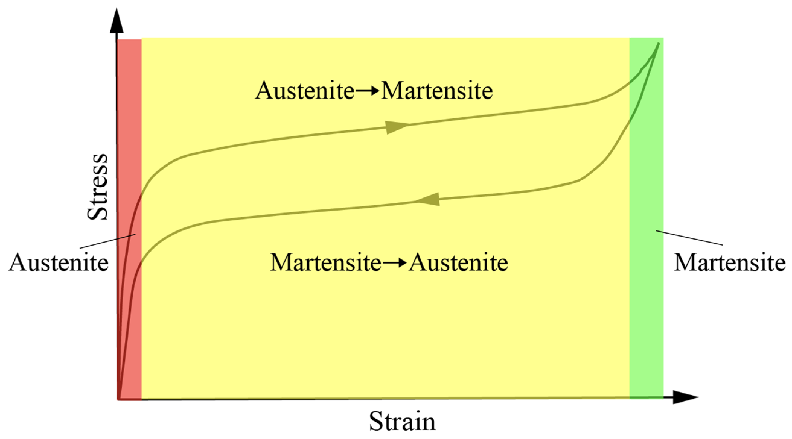
As shown in Figure 1, the stress–strain curve of a superelastic NiTi shape memory alloy mainly consists of three stages: Stage 1, elastic deformation of austenite; Stage 2, phase transformation from austenite to martensite; and Stage 3, elastic deformation of martensite. If loading continues, the material will undergo plastic deformation and eventually fracture once the martensitic limit load is exceeded. During loading, the mechanical behavior of SMA is similar to that of an elastoplastic material with hardening. The essential difference is that, within a certain deformation range, SMA can recover most of the deformation accumulated in Stage 2. As a result, upon reloading, the residual deformation from the previous loading cycle remains relatively small.
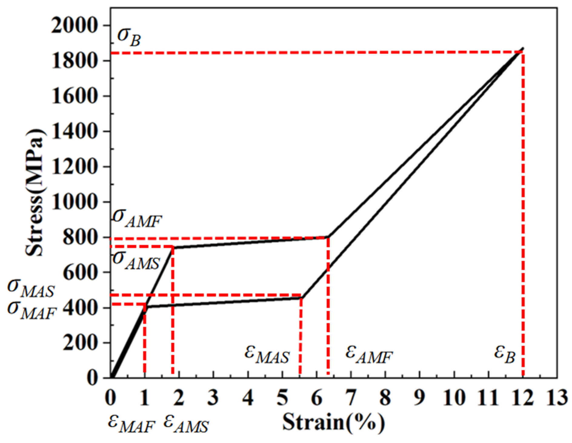
Inspired by classical phenomenological models (Auricchio [59]), the superelastic material behavior of SMA is idealized and linearly simplified into a four-stage piecewise constitutive model, as shown in Figure 2. Here, EA denotes the elastic modulus of austenite, EM denotes the elastic modulus of martensite, and EAM denotes the equivalent elastic modulus during the austenite-to-martensite transformation. σAMS and σAMF denote the start and finish stresses of the austenite-to-martensite transformation, respectively, while σB denotes the martensitic yield stress. Correspondingly, εAMS and εAMF denote the start and finish strains of the austenite-to-martensite transformation, and εB denotes the martensitic yield strain.
The constitutive relation of the material can then be written as follows:
σ ( ε ) = E A ε   0 ε ε A M S σ A M S + E A M ( ε ε A M S ) ε A M S ε ε A M F σ A M F + E M ( ε ε A M F ) ε A M F ε < ε B σ B ε ε B
ε A M S = σ A M S E A ε A M F = ε A M S + σ A M F σ A M S E A M ε B = ε A M F + σ B σ A M F E M
where ε denotes the uniaxial material strain, and σ(ε) is the corresponding stress.
This piecewise linear simplification is of paramount importance for the proposed hybrid model. In structural mechanics, utilizing fully nonlinear phenomenological constitutive models typically requires complex iterative algorithms (e.g., the Newton–Raphson method) at the integration point level, which is computationally expensive. In contrast, this linearized approach allows for direct and rapid stress state determination. This mathematical simplification significantly accelerates the subsequent cross-sectional fiber integration and inverse mapping procedures without compromising the essential physical features of the SMA.

3. Prediction Model for Structural Residual Deformation

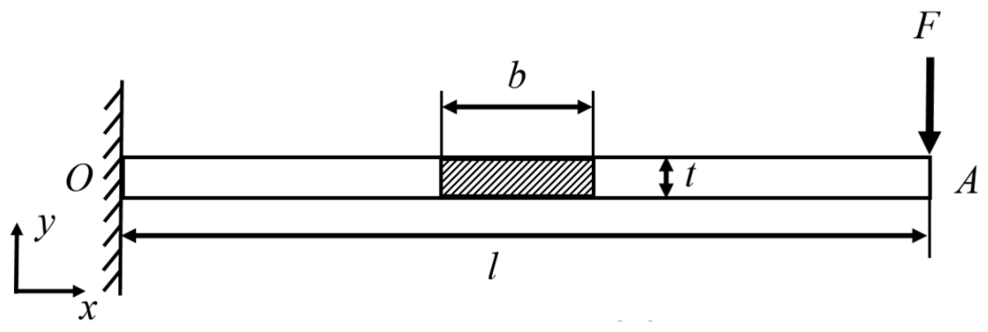
According to the classical cellular solids theory by Gibson and Ashby [64], when a regular hexagonal honeycomb is subjected to macroscopic in-plane compression, the dominant deformation mode of the inclined cell walls is transverse bending rather than pure axial tension or compression. Accordingly, a prediction model is established for the residual deformation of an SMA beam under bending. A single cell wall in the honeycomb unit is idealized as a cantilever beam, as shown in Figure 3, with length l, cross-sectional thickness t, and cross-sectional width b.
Neglecting the shear force Q in the beam, the strain at any point on the beam satisfies the following relationship with the curvature:
ε ( x , y ) = k ( x ) y
The relationship between the cross-sectional bending moment M and the curvature k is given by the following:
M ( k ) = 2 b 0 t / 2 σ ( k y ) y d y
Denoting the nonlinear relationship between the cross-sectional bending moment M and the curvature k by the operator M, the curvature can be obtained through the inverse mapping because this nonlinear relationship is monotonically increasing:
k = M 1 ( M )
Once the section enters the elastoplastic and phase-transformation stages, the stress distribution evolves through complex boundaries within the integration domain. As a result, the operator M becomes a highly complicated implicit function, and an explicit closed-form inverse M−1 does not exist mathematically. In this study, numerical discretization and interpolation are adopted to construct the inverse mapping model. Specifically, a discrete curvature sequence ki is first generated within a reasonable range, and the corresponding bending moment sequence Mi is then calculated accurately through forward layered fiber integration. Based on this discrete dataset, a linear interpolation function or spline interpolation function is established, thereby reducing the computational cost while maintaining sufficient accuracy.
For a cell wall, the loading condition corresponds to applying a force F at one end of the cantilever beam. The deflection distribution of the beam can be expressed as follows:
w ( F ) = 0 L x k ( x ) d x = 0 L x M 1 ( F x ) d x
Because of the nonlinear and implicit characteristics of M−1 in the integrand, this integral equation cannot be analytically inverted to obtain an explicit expression of the load F in terms of the deflection w. Therefore, the inverse load determination is transformed into a scalar nonlinear root-finding problem. The objective function is defined as follows:
f ( F ) = w ( F ) w l o a d = 0
Taking advantage of the monotonic increase of f(F) with respect to the load, the load F can be obtained through numerical iteration, and the curvature distribution along the beam during loading is then determined as follows:
k l o a d ( x ) = M 1 ( M ) = M 1 ( F x )
After unloading, the actual residual rotation angle and residual deflection of the cantilever beam can be obtained by integrating the actual residual curvature kres(x) along the X-direction. The actual residual curvature must be determined from the post-unloading sectional state.
For shape memory alloys, the recoverable strain after unloading depends on the loading history. Fibers at different heights y within the same cross-section experience different maximum strains and therefore possess different free residual strains εfree after unloading. Deformation accumulated within the austenite elastic stage and the austenite-to-martensite transformation stage can be fully recovered. When loading enters the martensitic hardening stage, both elastic strain recovery and transformation strain recovery occur. Once loading reaches the martensitic yielding stage, only elastic strain recovery remains. The maximum strain at position (x,y) during loading is given by the following:
ε max ( x , y ) = k l o a d ( x ) y
ε f r e e ( y ) = sgn ( y ) 0 ε max ε A M F ε max σ ( ε max ) E A δ ε ε A M F ε max ε B ε max σ B E A ε max > ε B
sgn ( y ) = 1 y < 0 0 y = 0 1 y > 0
δ ε = ε A M F ε A M S
However, the plane-section assumption must still be satisfied within the same cross-section, which means that fibers at different heights constrain one another and an internal force redistribution occurs within the section. After unloading, the beam returns to a sectional equilibrium state with zero bending moment and zero axial force, so that the sum of the moments of the residual stresses σres of all the fibers about the neutral axis is zero. The residual stress state can be calculated from the difference between the actual residual strain and the free residual strain. The post-unloading sectional state is then determined using the fiber integration method:
M r e s = A σ r e s ( y ) y d A = 0
σ r e s ( y ) = E A ( k r e s y ε f r e e ( y ) )
Accordingly, the residual curvature kres can be written as follows:
k r e s ( y ) = 1 I A ε f r e e ( x , y ) y d A = 2 h I 0 t / 2 ε f r e e ( x , y ) y d A
The actual residual rotation angle and residual deflection can then be obtained by integration as follows:
φ r e s = 0 L k r e s ( x ) d x
w r e s = 0 L x k r e s ( x ) d x

4. Simulation and Reusable Energy Absorption Analysis of SMA Honeycomb Structures

4.1. Uniaxial Tensile Test of SMA and Identification of Material Parameters

Dassault Systèmes SIMULIA ABAQUS 2021 software was employed as the finite element simulation platform, in which the keyword Superelasticity was used to invoke the superelastic SMA material model. This model is a macroscopic phenomenological constitutive model proposed by Auricchio [59], based on the martensitic volume fraction ξ, and it exhibits satisfactory computational efficiency and accuracy for structural design problems.
The constitutive relations can be expressed as follows:
E = E A + ξ ( E M E A )
ν = ν A + ξ ( ν M ν A )
ξ ˙ = H AS ( 1 ξ ) F ˙ AS F f AS + H SA ξ F ˙ SA F f SA
where HAS and HSA are scalar parameters used to characterize the phase transformation; FAS is the state equation for the austenite-to-martensite transformation; FSA is the state equation for the martensite-to-austenite transformation; and F f AS and F f SA denote the state equations corresponding to complete austenite-to-martensite and martensite-to-austenite transformations, respectively.
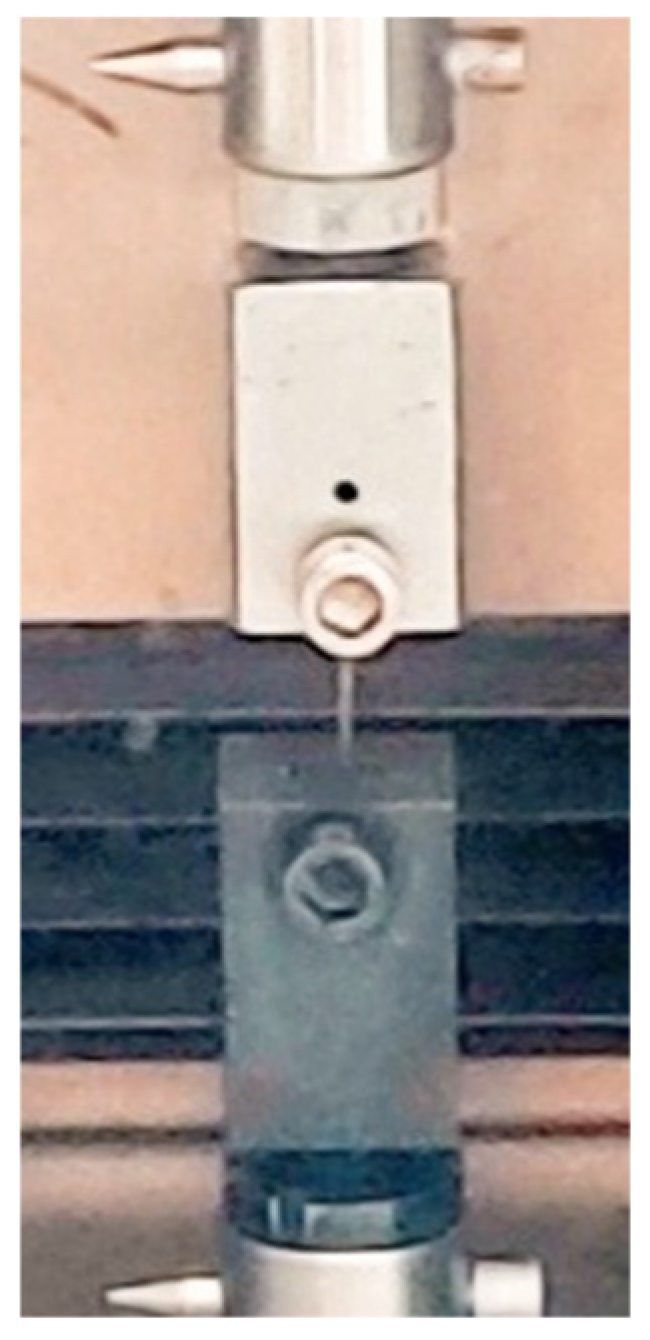
As shown in Figure 4, the tests were carried out on NiTi wires with a length of 80 mm using a WDT II-10 universal testing machine at an ambient temperature of 30 °C.
NiTi alloy wires with an atomic ratio of 51:49 were used in uniaxial tensile tests to determine the SMA material parameters. The NiTi wire specimens were prepared from cast ingots through cutting, wire drawing, and annealing. A loading–unloading cycle with a total strain of 8% was applied, and the force-displacement data were recorded throughout the test.
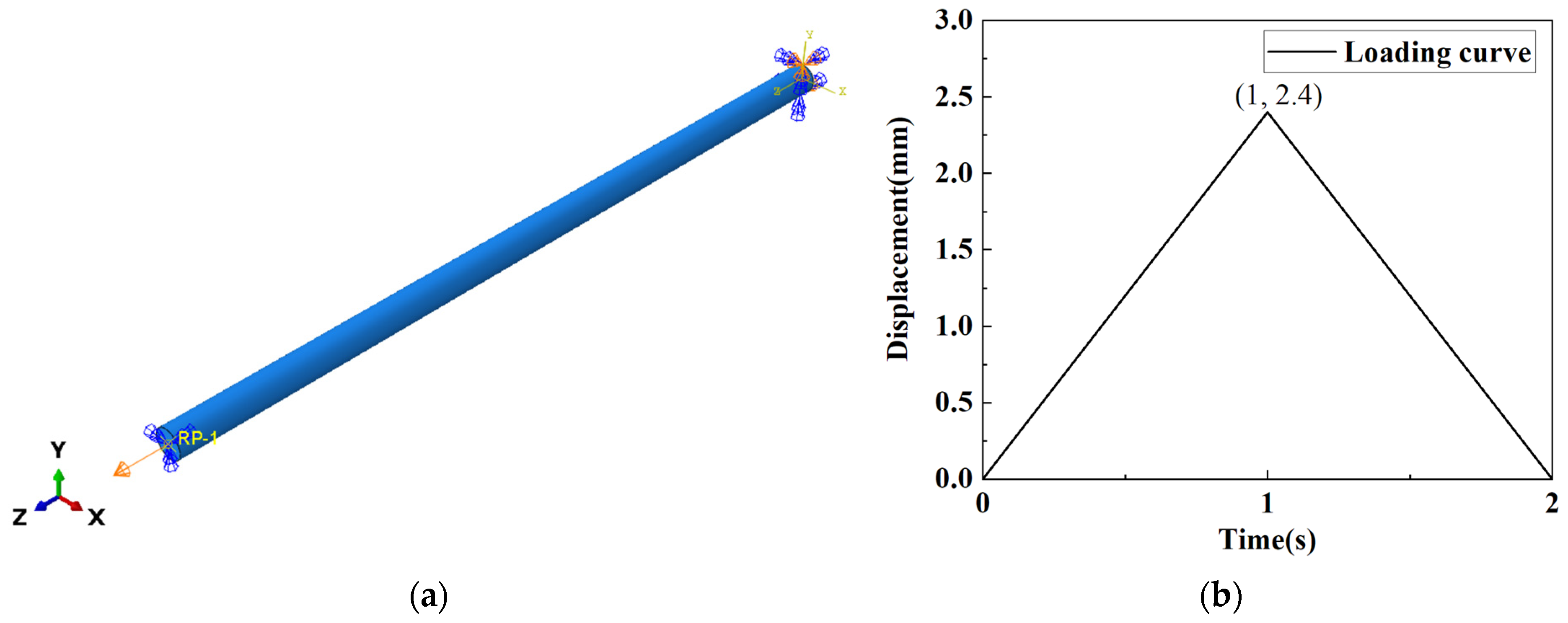
A finite element model of the NiTi wire, as shown in Figure 5, was then established for the tensile loading–unloading simulation. The model had a length of 30 mm and a cross-sectional area of 1 mm2. The mesh was generated using C3D8R elements with a mesh size of 0.2 mm. The imposed tensile displacement was 2.4 mm, corresponding to 8% of the total wire length.
By analyzing the physical meaning of the constitutive parameters together with the experimental results, the simulation parameters of the superelastic NiTi wire were determined, as listed in Table 1.
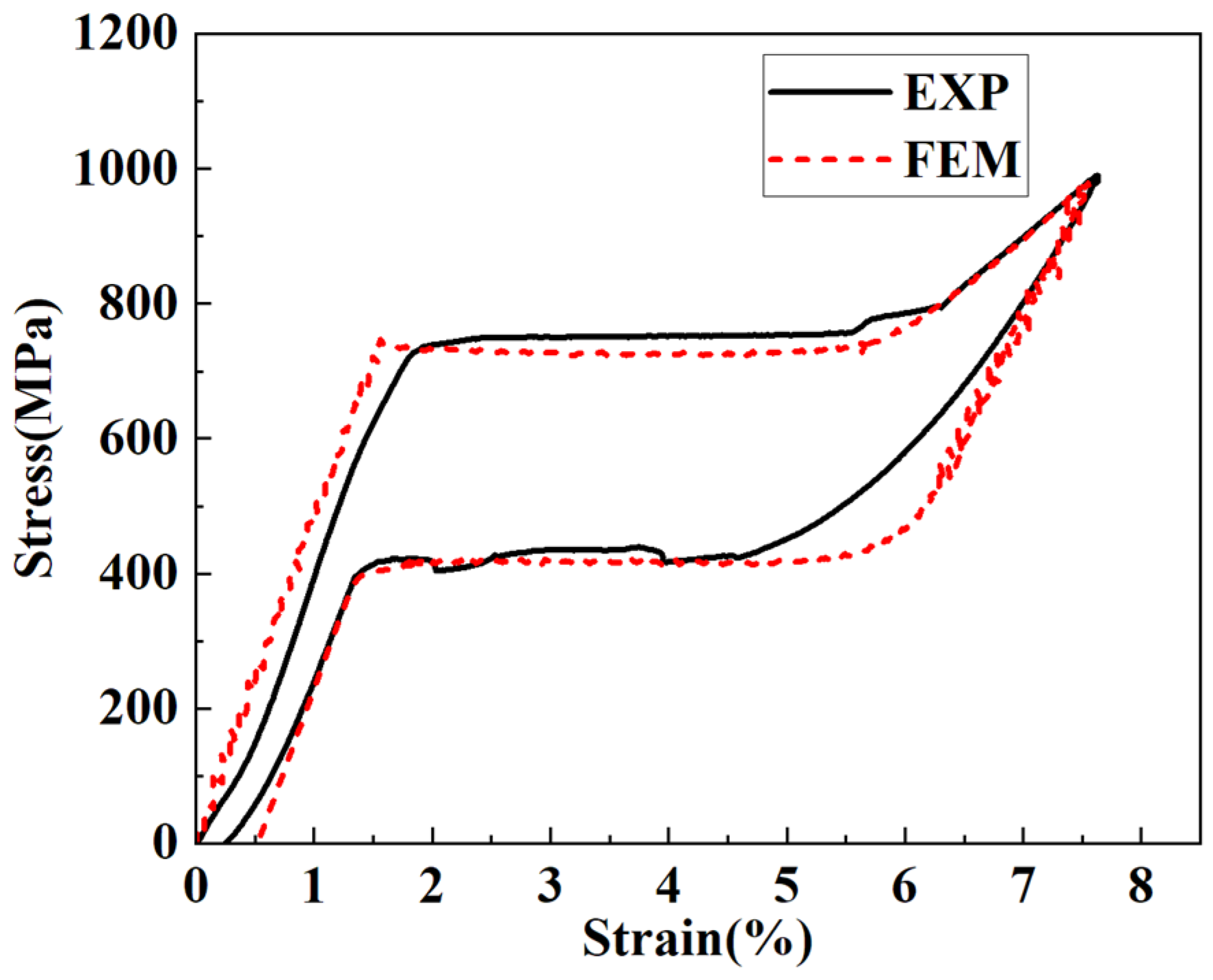
As shown in Figure 6, the comparison between the simulated and experimental stress-strain curves of the NiTi wire during tensile loading and unloading indicates that when the material parameters in Table 1 are adopted, the superelastic SMA model in ABAQUS reproduces the mechanical behavior observed in the tensile experiment with relatively small deviations in the key mechanical properties. This confirms the reliability of the adopted material model and provides a sound basis for the subsequent numerical investigation of the reusable buffering performance of SMA honeycomb structures.

4.2. Simulation of the Reusable Energy Absorption Performance of SMA Honeycomb Structures

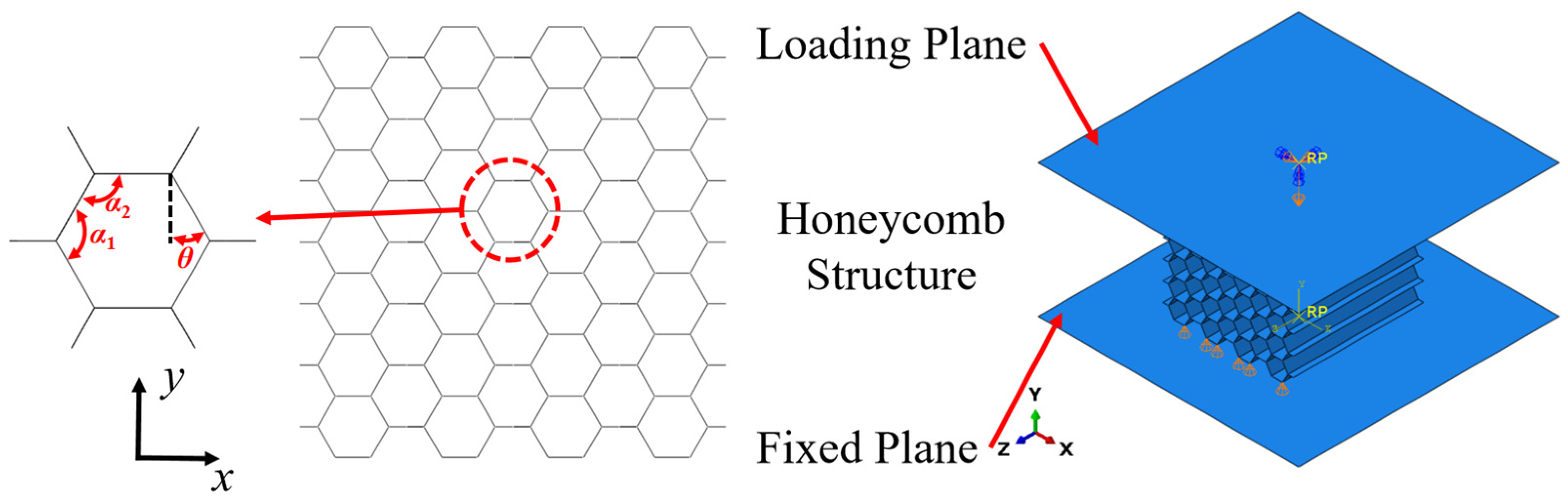
A finite element model of a regular hexagonal straight honeycomb structure was established, as shown in Figure 7. The cell wall length and thickness were set to 10 mm and 0.5 mm, respectively, and the overall envelope dimensions were 120 mm × 121.24 mm × 120 mm. The SMA superelastic constitutive model was assigned using the Superelasticity keyword together with the previously validated material parameters.
As detailed in our previous work [65], a mesh convergence study was conducted comparing element sizes of 0.4 mm, 0.5 mm, 1.0 mm, 1.25 mm, 2.0 mm, and 2.5 mm. The results indicate that the 1.0 mm mesh size provides an optimal balance, yielding highly converged stress and energy absorption results (with relative differences of less than 7% compared to the 0.4 mm mesh) while significantly reducing computational cost. Therefore, the mesh size of the straight honeycomb model was set to 1.0 mm, and S4R shell elements were adopted. The compression loading–unloading process was realized by means of two analytical rigid planes. A uniform downward displacement was directly applied to the reference point (RP) coupled to the top rigid plane, ensuring uniform macroscopic compression across the honeycomb. The mass of each rigid plane was set to 10,000 kg, and the loading velocity was 1 m/s. General contact was defined with a friction coefficient of 0.1. Since the local deformation of the honeycomb becomes extremely large after densification and far exceeds the recoverable deformation capacity of SMA, an appropriate loading length should be specified for reusable honeycomb structures. Referring to previous studies on metallic and aluminum honeycomb crushing, in which the effective crushing stroke before densification is commonly taken to be approximately 70% of the initial height [64,66], and to studies showing that SMA honeycombs can still recover most of their deformation at an overall strain of 60% [37], the loading length in the present simulation was set to 70% of the total length of the model along the loading direction.
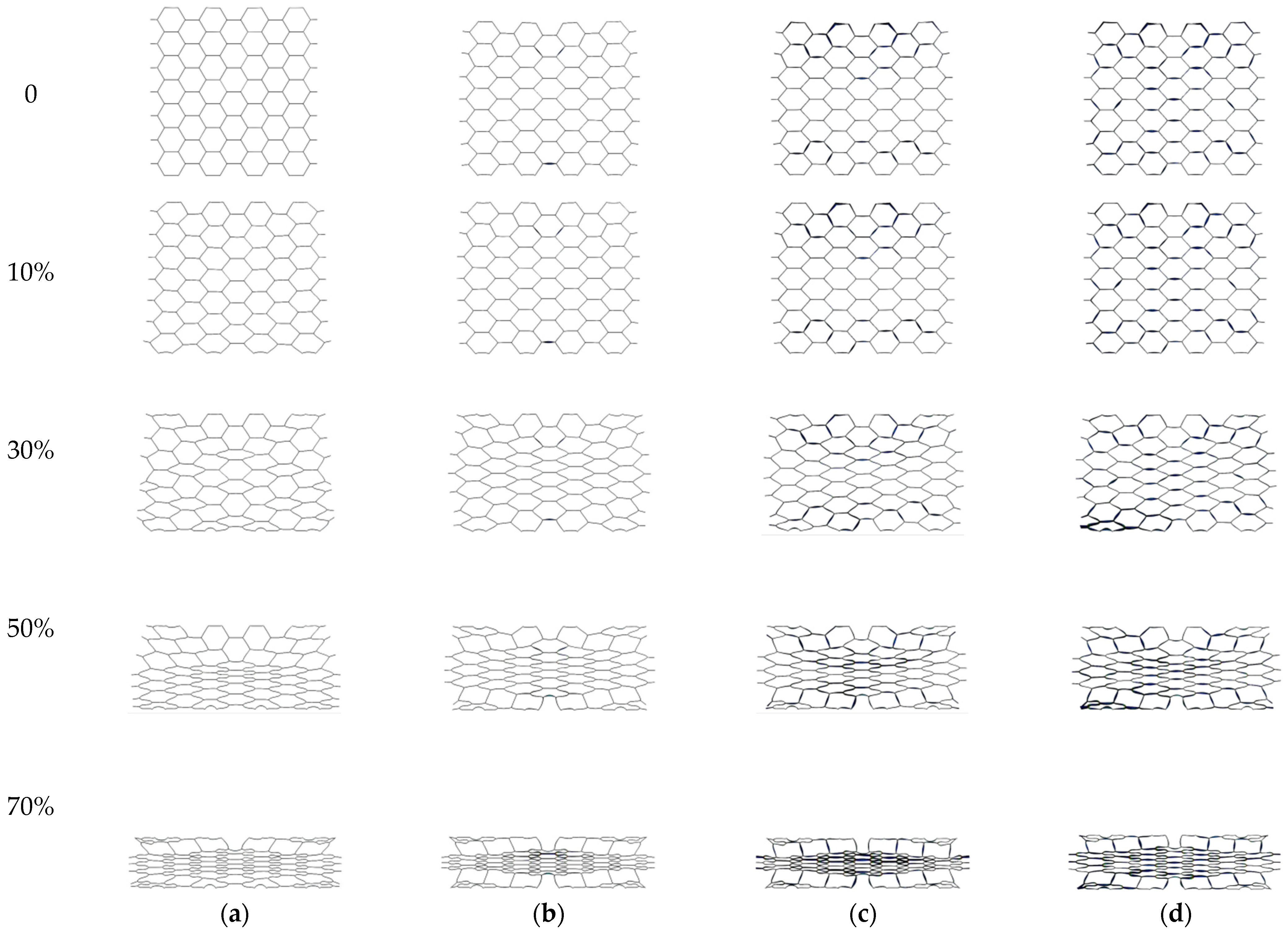
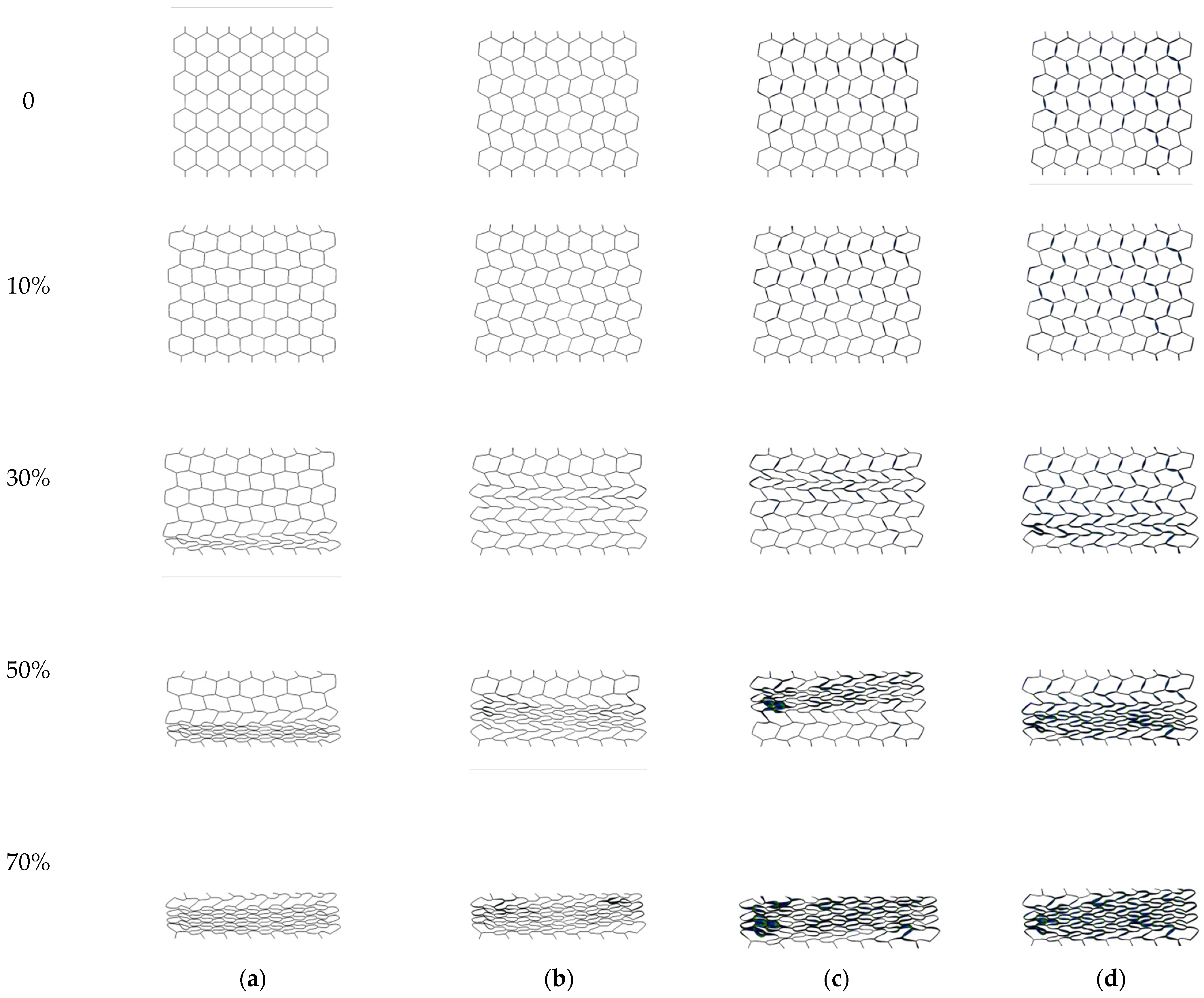
Although Figure 7 illustrates the finite element boundary conditions using the Y-direction loading setup as a representative example, to systematically present the structural responses, the deformation under X-direction loading is analyzed first. As shown in Figure 8, during the first compression in the X-direction, the deformation process of the regular hexagonal SMA honeycomb is similar to that of an aluminum honeycomb. Specifically, the inclined cell walls first undergo bending, after which the vertical cell walls lose stability and in turn drive the inclined cell walls to rotate about the cell-wall junctions. Once torsional deformation occurs in one layer of the honeycomb, the internal constraints of the structure are altered, resulting in an alternation of clockwise and counterclockwise torsional deformation among different layers as compression proceeds. Plastic hinges are mainly concentrated at the cell-wall junctions. After complete unloading from the first cycle, some of the plastic hinge deformation near the junctions exceeds the recoverable deformation threshold of the material, thereby generating residual deformation. As a consequence, the torsional deformation around the cell-wall junctions is retained, giving rise to the staggered inclined configuration observed before the second loading cycle.
The reusable energy-absorbing deformation process of the regular hexagonal honeycomb under Y-direction loading is illustrated in Figure 9. As compression proceeds, the inclined cell walls undergo bending deformation, and plastic hinges form at both ends of the inclined walls, which constitutes the main energy absorption mechanism under Y-direction loading. The initial deformation process of the SMA honeycomb in the Y-direction is similar to that of the aluminum honeycomb. Under the influence of boundary constraints, once the structure is compressed by 30%, an “X”-shaped collapse band forms with the central cell as the center. With further compression, the honeycomb cells in the central region exhibit symmetric and relatively uniform deformation.
Comparison of the structural features of the unloaded honeycomb after different loading cycles shows that after compression, the influence of residual deformation in the cell walls causes the honeycomb to evolve from the initial regular hexagonal configuration into a non-regular reusable configuration. In subsequent loading cycles, the asymmetric internal constraints of this reusable configuration act as geometric imperfections, inducing the structure to repeat the deformation mode established during the initial loading process and thereby forming a relatively stable deformation pattern.
Furthermore, Table 2 and Table 3 compare the variation in the internal angles of the central cell with the number of loading cycles in the X- and Y-directions, respectively. For X-direction loading, after the first cycle, interior angle α1 stabilizes at approximately 125°, while interior angle α2 stabilizes at approximately 107°. For Y-direction loading, after the initial loading–unloading cycle, interior angle α1 stabilizes at approximately 100°, while interior angle α2 stabilizes at approximately 129°. The change in the cell interior angles provides a quantitative description of the effect of cell-wall residual deformation on the structural configuration during the first loading cycle, thereby confirming the evolution of the honeycomb from its initial configuration to a reusable configuration, as well as the stability of this reusable configuration during subsequent loading cycles.
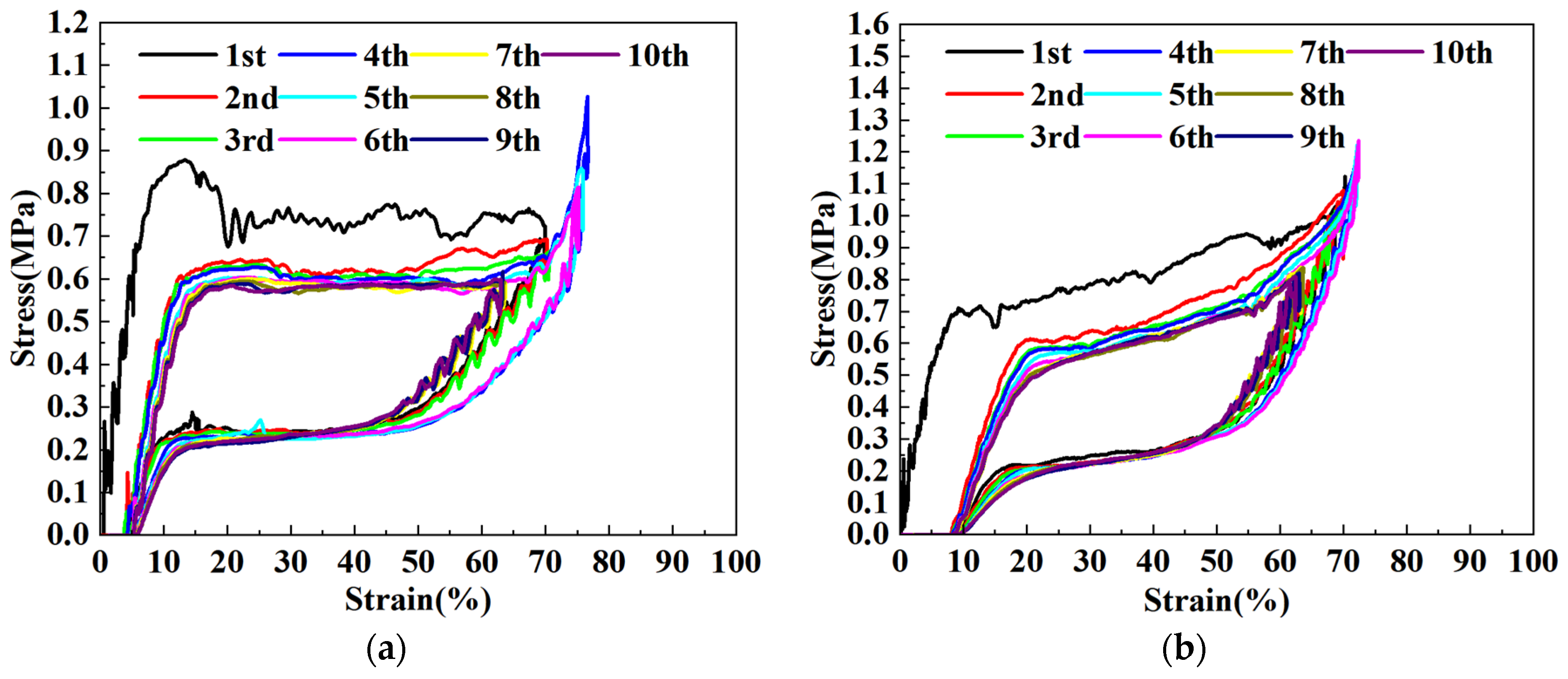
Figure 10 presents the stress–strain curves of the SMA regular hexagonal straight honeycomb over ten loading–unloading cycles. Analysis of the variation in the stress–strain response with increasing cycle numbers shows that after the initial loading–unloading cycle, the energy absorption performance decreases due to the presence of residual deformation but gradually tends toward stability in the subsequent cycles. This preliminarily demonstrates that the transition from the initial configuration to the reusable configuration leads to a change in the energy absorption performance of the honeycomb. In the following loading cycles, because the structural configuration remains essentially stable, the positions, number, and deformation extent of the plastic hinges do not change significantly; accordingly, the energy absorption performance also remains nearly stable as the number of loading cycles increases.
Plateau stress is one of the most commonly used indicators for evaluating energy absorption performance. It is used to characterize the general level of the reaction force during the plastic deformation and energy absorption process of the honeycomb structure. Equation (21) shows that plateau stress is calculated by dividing the total absorbed energy before densification by the product of the deformation displacement and the projected area [64]. Referring to ISO 13314:2011 [67], which defines the energy absorption efficiency and the end point of the plateau region, the onset of the monotonic decrease in energy absorption efficiency is defined in this study as the end point of the plateau region, as shown in Figure 11 and Equation (22).
The corresponding expressions are as follows:
σ * = x 0 x 1 F d x ( x 1 x 0 ) A
η = W F x × 100 = ε 0 ε x σ d ε σ ( x ) ε ( x ) × 100
where x0 denotes the initial position of the structural energy absorption process; x1 denotes the final position of the energy absorption process, which is generally taken as 60–70% of the total structural length; F is the resisting force during structural deformation; and A is the projected area of the structure normal to the loading direction.
Because SMA exhibits a relatively large nonelastic deformation capacity, the cell walls of the SMA honeycomb undergo partial plastic deformation after exceeding the initial yield point during loading. However, before a fully developed plastic hinge forms, the cell walls first experience elastic instability due to geometric nonlinearity. Therefore, in this study, the fully plastic moment Mp = σyt2/4 in the plateau stress formulas for honeycombs loaded in the X- and Y-directions, originally proposed by Gibson, is replaced here by the elastic limit moment Me = σyt2/6. Consequently, the adapted plateau stress formulas for honeycombs loaded in the X- and Y-directions are derived as follows:
σ * σ y = t l 2 1 3 cos 2 θ
σ * σ y = t l 2 1 3 ( 1 + sin θ ) sin θ
Table 4 and Table 5 compare the theoretical plateau stresses obtained by substituting the structural parameters at different loading cycles into Equations (23) and (24) with the corresponding simulation results. The theoretical and simulated plateau stresses are in relatively good agreement, directly demonstrating that the structural configuration is the primary factor governing the energy absorption performance of the honeycomb. The increase in relative error with increasing loading cycles further indicates that although the structure tends toward stability as the number of cycles increases, the accumulated residual deformation changes the length of the cell walls, causing the simulation results to gradually deviate from the theoretical predictions.
R E = σ T h e o r y σ F E M σ F E M × 100 %
In summary, after an SMA honeycomb structure is compressed, residual deformation is generated upon unloading once the local large deformation exceeds the recoverable threshold of the material. This residual deformation changes the structural configuration, transforms the initial configuration into a reusable one, and correspondingly affects the energy absorption performance. In this sense, the problem of reusable energy absorption performance in SMA honeycombs can be reformulated as a problem of residual deformation in SMA structures. Therefore, by using the structural residual deformation prediction model based on the reusable constitutive model proposed above, it becomes possible to predict the reusable energy absorption performance of honeycomb structures under specified material properties, structural configurations, and loading conditions.

5. Discussion

5.1. Model Validation and Data Calibration Analysis

To validate the proposed residual deformation prediction model, a cantilever beam model with a rectangular cross-section was established in ABAQUS using the superelastic SMA material parameters identified above. All degrees of freedom at the left end of the cantilever were fixed, while a negative displacement load was applied along the Y-axis at the right end. The model was meshed using B23 elements, with a beam length of 10 mm, a section thickness of 1 mm, a section width of 40 mm, and a mesh size of 0.25 mm.
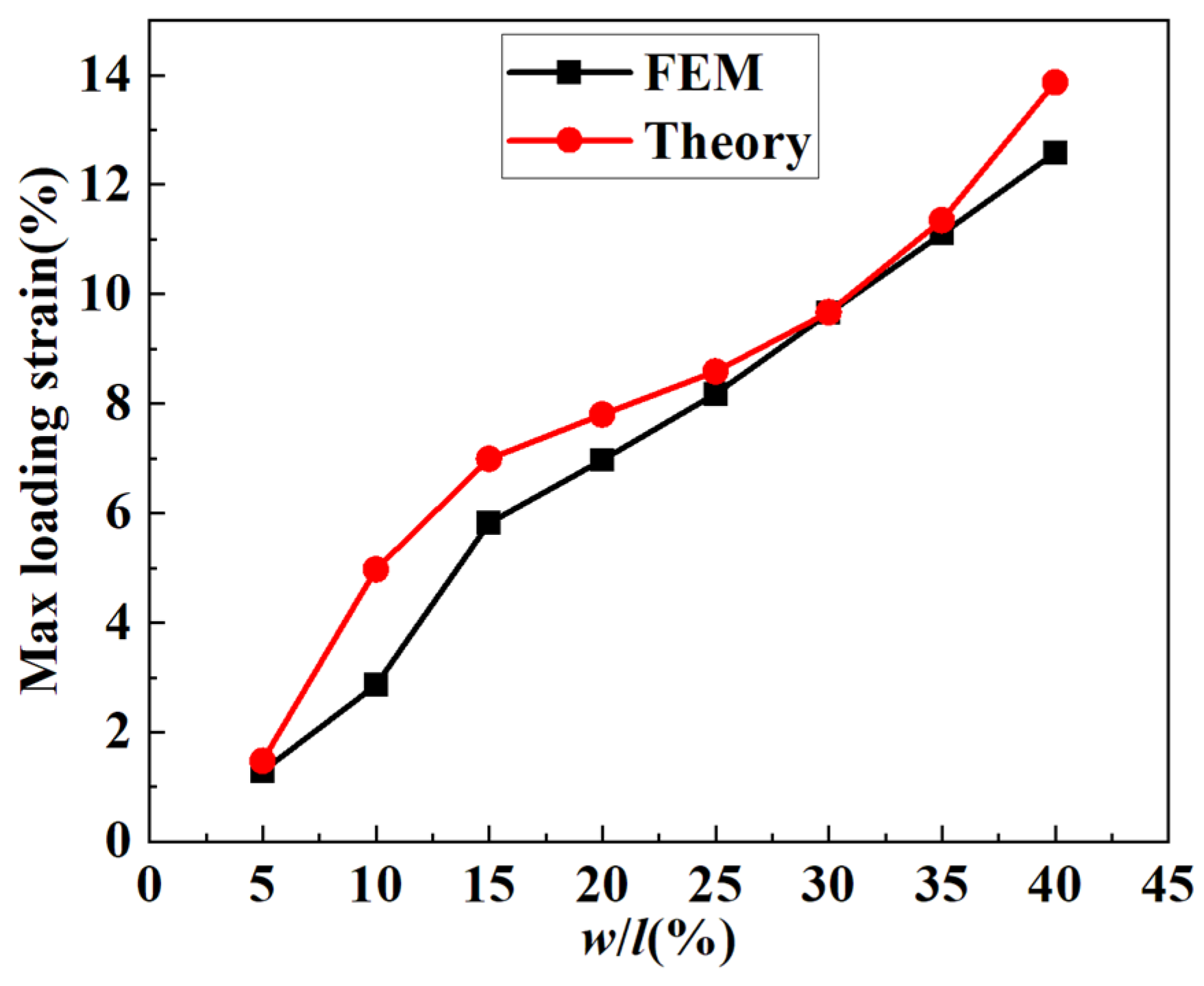
At the free end of the cantilever, negative Y-direction displacements corresponding to 5–40% of the beam length were applied. The maximum strain at the beam root and the residual displacement in the Y-direction at the free end after unloading were measured, and the discrepancies between the simulation results and the theoretical predictions were comparatively analyzed. As shown in Figure 12, the theoretical and simulated results for the maximum strain in the cantilever are in relatively good agreement, indicating that the proposed mechanical model can accurately predict the loading behavior of SMA. Throughout the entire loading process, the theoretically predicted maximum strain remains higher than that obtained from FEM, and the relative error reaches its maximum when the deflection ratio is approximately 10%, after which it rapidly converges to within 10% in the large-deformation range corresponding to 25–40% of the beam length.
The main source of this error lies in the abrupt local curvature variation introduced by the linearly simplified constitutive model. When the stress at the fixed end just reaches the phase transformation threshold, the theoretical tangent modulus drops suddenly by about 95%. In order to satisfy the prescribed macroscopic target deflection, the analytical model mathematically forces an extreme strain concentration at the beam root. By contrast, FEM benefits from the smooth constitutive transition and the realistic redistribution of stress, thereby effectively alleviating this single-point strain concentration. As the loading deflection increases further (>15%), the phase-transformation softening zone expands sufficiently from the root toward the mid-span of the beam, and the local curvature concentration is greatly diluted. As a result, the global curvature distribution predicted by the analytical model gradually converges toward that obtained by FEM, and the error rapidly falls to within 10%.
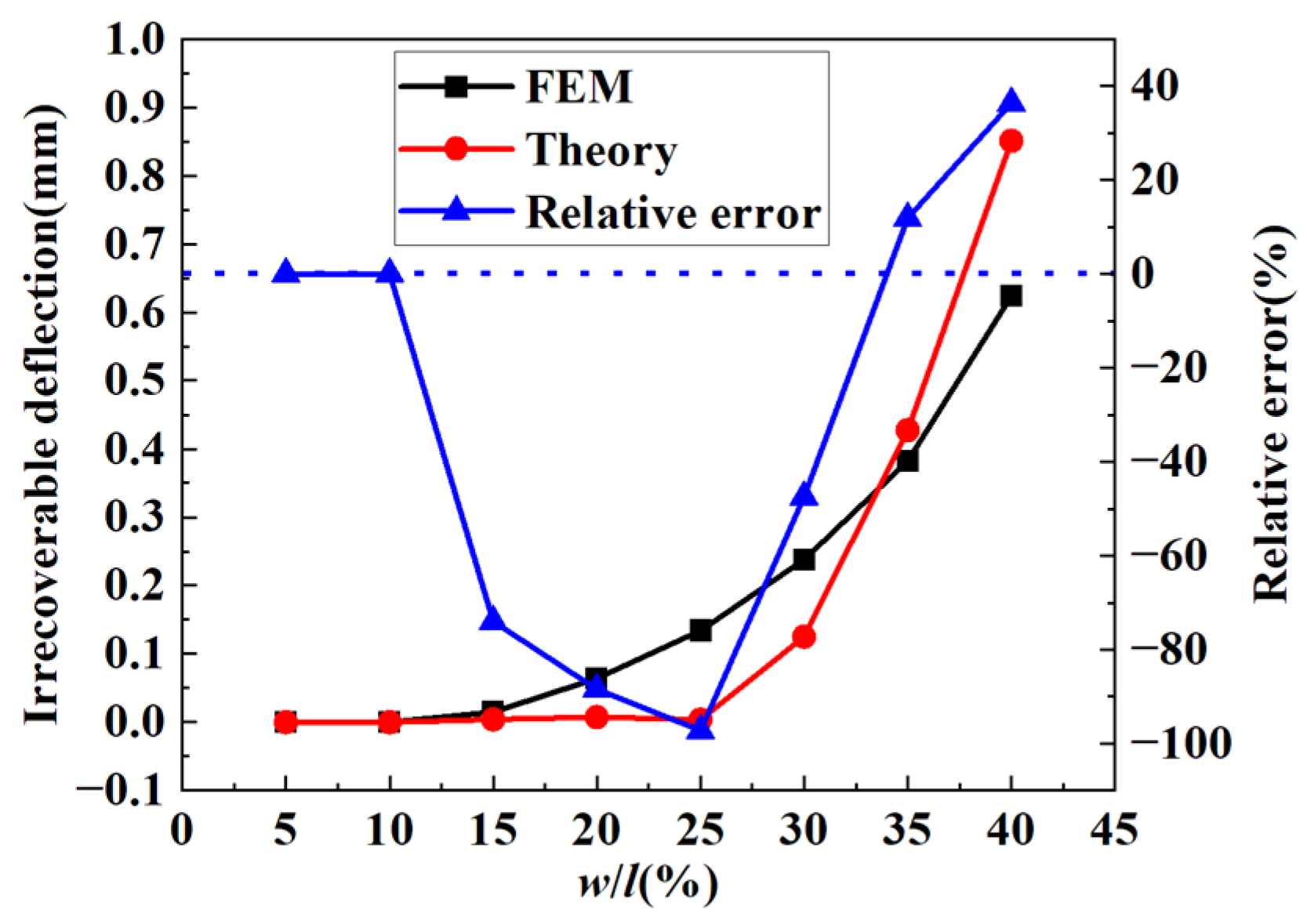
Figure 13 provides a direct comparison between the theoretical and FEM results for the residual deflection of the cantilever after unloading from bending deformation, together with the variation in the relative error with loading level.
As indicated by the curves, the evolution of residual deformation can be clearly divided into three physical stages.
(1)
Zero-residual stage (w/l ≤ 10%): Within the small- to moderate-deformation range, the local maximum strain remains strictly within the phase transformation plateau, and all deformation is fully recovered. Both the theoretical and FEM results therefore accurately predict zero residual deformation.
(2)
Theoretical lag stage (10% < w/l ≤ 25%): As the deformation increases, the FEM model begins to capture a gradually increasing irrecoverable deflection, whereas the theoretical prediction still remains zero, causing the relative error to increase sharply in this interval. The reason is that the linearly simplified constitutive model strictly uses the martensitic yield strain as the criterion for the onset of residual strain, while in the FEM model, with increasing strain, the martensitic volume fraction also continuously increases, and the martensite-dominated material behavior leads to ongoing plastic accumulation in the structure.
(3)
Theoretical surge stage (w/l > 25%): When the deformation becomes sufficiently large and the theoretical strain finally exceeds the martensitic yield strain, residual deformation begins to develop, and an increasing amount of residual deformation is integrated into the residual deflection. Meanwhile, the geometrically linear integration path based on the undeformed initial configuration is no longer applicable under large deflection, and it incorrectly amplifies the local residual curvature near the root at the macroscopic level, ultimately causing the theoretically predicted residual deflection to increase exponentially.
Although the analytical framework based on one-dimensional idealized assumptions can describe the stiffness evolution during loading at extremely low computational cost, the residual strain formula obtained solely from idealized uniaxial algebraic subtraction cannot faithfully reproduce the complex rebound path in node regions under severe deformation, where three-dimensional stress coupling and geometric nonlinearity become significant. To fundamentally bridge this cross-scale gap between physical reality and theoretical approximation, and to ensure the fidelity of reusable energy absorption predictions for honeycomb structures in the extreme deformation regime, this study proposes a semi-analytical and data-calibrated constitutive framework.
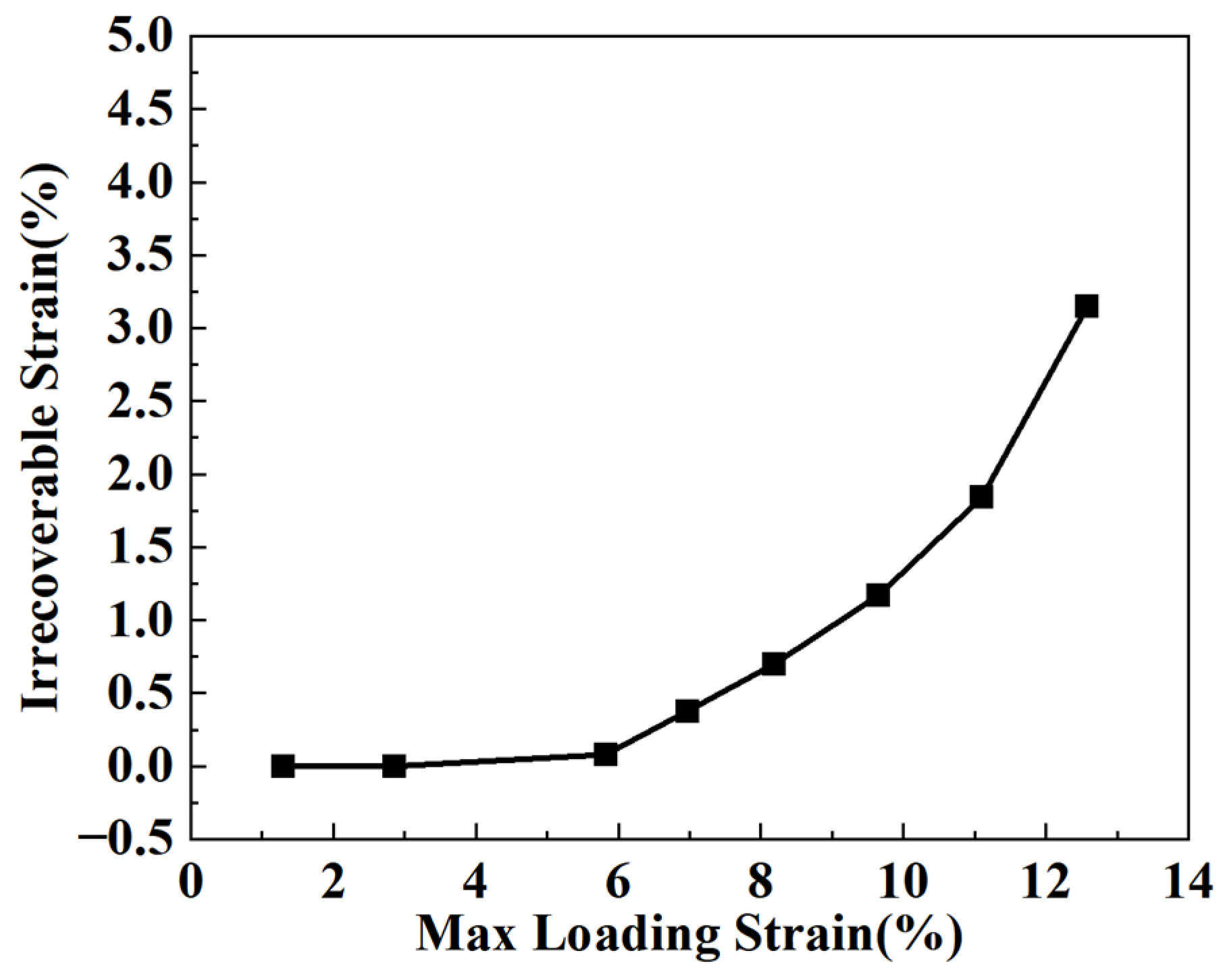
Specifically, a material-level loading strain–unloading residual strain relationship was first obtained from the uniaxial tensile loading–unloading finite element model established in Section 4.1. This dataset was extracted by imposing different maximum tensile strain levels on the calibrated NiTi wire model and recording the corresponding irrecoverable strain after complete unloading. Within the globally accurate nonlinear analytical integration framework, the material-level relationship shown in Figure 14 was embedded to calibrate the microscopic unloading residual strain relation.
As shown in Table 6, after correcting the residual strain in the theoretical model using the loading strain–unloading residual strain curve, the theoretical residual deflection agrees well with the FEM result, with a relative error below 5%. This indicates that the corrected mechanical model possesses strong predictive capability for the residual deflection of a cantilever beam after unloading from pure bending.
Based on the linearly simplified superelastic constitutive model of SMA, together with the actual loading strain–unloading residual strain data, a semi-analytical and data-calibrated prediction model linking material residual strain to structural residual deformation was established under known structural parameters and material properties. This model enables accurate prediction of the residual deformation of structures made of materials with recoverable inelastic deformation after unloading and further provides the theoretical basis for predicting the residual deformation of SMA honeycomb structures, as well as for deriving their reusable configurations and reusable energy absorption performance.

5.2. Prediction of Residual Deformation in Honeycomb Structures

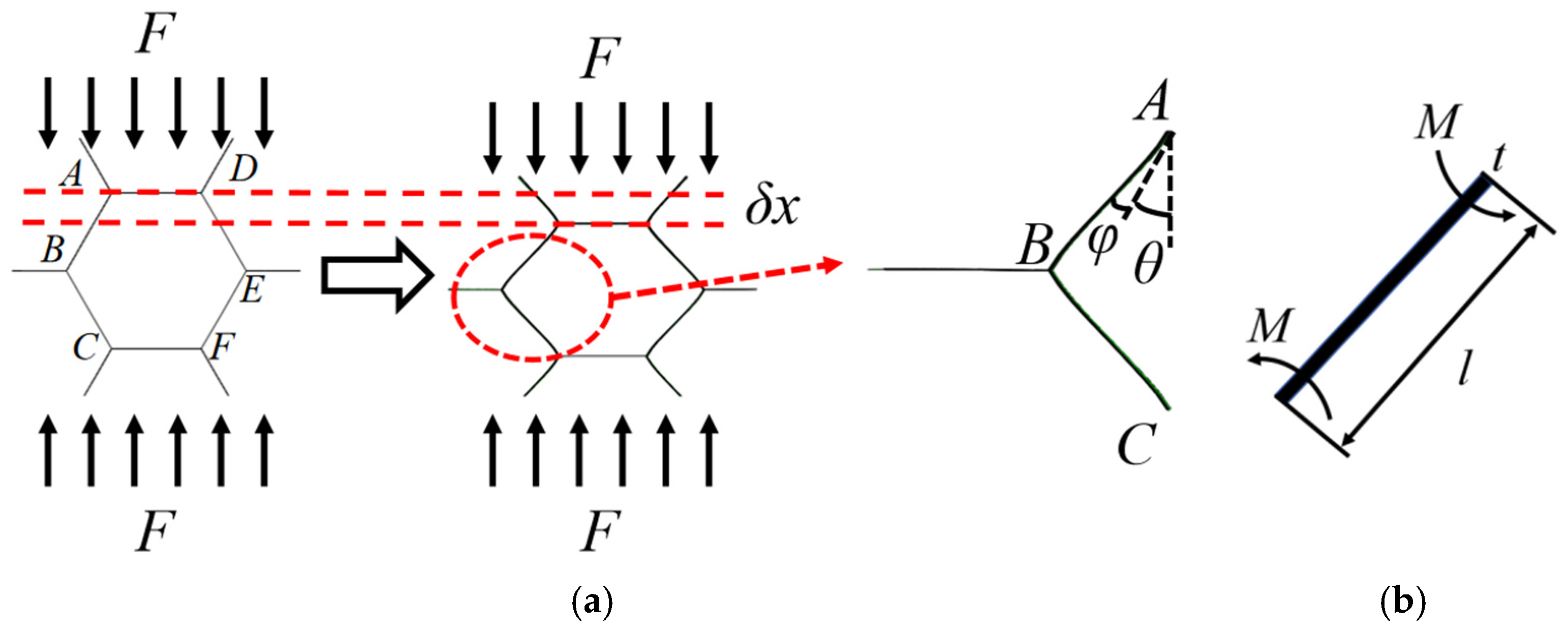
A single cell in an infinitely large regular hexagonal honeycomb was selected as the object of analysis. It should be noted that the model in this section is an independent verification case with scaled geometric parameters, rather than the full finite element honeycomb model discussed in Section 4.2. This simplified single-cell model is used to examine the predictive capability of the proposed semi-analytical and data-calibrated framework under controlled geometric and loading conditions. When the honeycomb is subjected to a load in the Y-direction as shown in Figure 15, the macroscopic deformation of the cell is denoted by δx, and beams AB, BC, DE, and EF undergo both axial compression and transverse bending. Since the axial compression is very small, it can be neglected, while transverse bending is the dominant deformation mode. Owing to the symmetry of the honeycomb structure, a complete description of the deformation and force state of the cell can be obtained by analyzing only one cell wall, namely, beam AB. Furthermore, because the horizontal cell walls AD and BC remain horizontal throughout the deformation process and do not rotate, the rotations at nodes A and B are both zero. Beam AB can therefore be regarded as a beam fixed against rotation at both ends while allowed to slide.
In establishing the macro-micro kinematic mapping, this study strictly distinguishes the large geometric deformation of the cell from the small- to moderate-deformation mechanics of the cell wall. As the macroscopic compressive strain gradually increases, the inclined walls of the honeycomb cell undergo significant macroscopic rigid-body rotation. If a small-deformation projection assumption based on the initial configuration were adopted, the local deflection would be severely underestimated.
Therefore, in the forward kinematic mapping stage, an exact large-deformation geometric chord-length equation is introduced to update the rotation state of the cell wall in real time, thereby obtaining the loading deflection accurately:
δ x = ε H e x l cos θ
w l o a d l 2 ( sin θ l o a d sin θ )
θ l o a d = arccos ( cos θ ( 1 ε H e x ) )
It is worth noting that this geometric kinematic framework demonstrates broad adaptability. By establishing the rigorous mathematical relationship between the local deflection of the structural cell wall and the macroscopic deformation of the overall structure, this derivation can be extended to predict the residual deformation of various cellular topologies.
Substituting the loading deflection wload into the residual deformation mechanics model presented above yields the residual deflection wres. Geometric kinematic analysis further shows that under the rigid-node assumption, the material tangent angle at the node remains equal to the initially prescribed angle θ, whereas the macroscopic geometric angle formed by the line connecting the nodes is affected by the residual deflection after unloading. The post-unloading chord angle of the cell-wall nodes can therefore be expressed as follows:
θ u n l o a d θ 0 + arctan 2 w r e s l
The overall residual deformation of the honeycomb structure, δxres, and the residual deflection wres satisfy the following:
δ x r e s = 2 l ( cos θ cos θ u n l o a d )
For this independent verification case, the initial angle was taken as θ = 30°, the cell-wall length as l = 20 mm, the wall thickness as t = 2 mm, and the wall width as b = 40 mm, allowing the residual deformation ratio and residual chord angle of the honeycomb cell under different loading deformation ratios to be calculated. In the analysis of the in-plane energy absorption performance of regular hexagonal honeycombs, the plateau stress of the structure can be predicted directly once the structural parameters, including wall length, wall thickness, wall angle, and material yield strength, are known.
Table 7 compares the theoretical and simulated values of the residual deformation ratio and reusable plateau stress of the honeycomb structure under different loading deformation ratios in the Y-direction. The relative errors between the theoretical and simulation results are small and all remain below 8%, indicating that the semi-analytical and data-calibrated residual deformation prediction model proposed in this study can achieve accurate prediction of both the reusable configuration and the reusable energy absorption performance of SMA honeycomb structures.
It should be noted that because evaluating macroscopic residual deformation directly from material-level unrecovered strain via semi-analytical mapping is a newly proposed methodology in this study, direct analytical counterpart data from other researchers are currently unavailable. However, the predictive trends of the proposed model align exceptionally well with the experimental phenomena widely reported in the literature. Traditional reusable design strategies conservatively utilize the SMA’s recoverable deformation limit as a strict geometric boundary, thereby leaving the generation, evolution, and subsequent structural impacts of residual deformation largely unexplored. In contrast, physical cyclic compression experiments on 3D-printed SMA honeycombs (e.g., Michailidis et al. [34] and Xiong et al. [37]) have universally demonstrated that after experiencing an initial non-recoverable deformation, the structural geometry self-adjusts into a stable reusable configuration, subsequently maintaining a highly stable plateau stress across multiple cycles. Our theoretical framework successfully captures this exact phenomenological evolution, providing a quantitative mathematical basis for designing post-yield reusable energy absorbers.

6. Conclusions

This study systematically revealed the residual deformation behavior and reusable energy absorption characteristics of SMA honeycomb structures under large-deformation impact through theoretical derivation, numerical analysis, and experimental material characterization.
A semi-analytical and data-calibrated prediction model for structural residual deformation based on the reusable constitutive relation was proposed in this study. By introducing a linear simplification of the material constitutive behavior to ensure computational efficiency, the model effectively resolves the implicit-function problem arising from the complex cross-sectional stress distribution during the phase transformation of SMA. As a result, accurate prediction of the residual deflection of SMA cantilever beams and the residual deformation ratio of honeycomb structures based on material residual strain is achieved. After correction using the actual loading strain–unloading residual strain data, the prediction error of the model is reduced to within 8%. Furthermore, compared to conventional nonlinear full-scale finite element simulations that typically require hours to run, this semi-analytical framework can output the structural residual deformation and plateau stress in mere seconds. By directly bridging the material-level and structural-level responses, it significantly reduces the computational cost of trial-and-error in engineering design.
A finite element model for the reusable energy absorption behavior of SMA honeycomb structures was further established. The results show that after the first loading event involving large deformation, the structure evolves from its initial regular hexagonal configuration into a stable non-regular reusable configuration due to the formation of local plastic hinges in the cell walls. This evolution process provides the structural basis for the transition of the energy absorption performance from the initial state to a stable reusable state. It also demonstrates the intrinsic relationship among material residual strain, structural residual deflection, reusable structural configuration, and reusable energy absorption performance.
Analysis of the evolution of the reusable energy absorption performance of SMA honeycomb structures further indicates that although a certain degree of residual deformation is generated during the first loading–unloading cycle and leads to a slight decrease in energy absorption performance, the SMA honeycomb is able to maintain highly stable plateau stress and deformation modes during subsequent repeated loading cycles. This demonstrates the great potential of SMA honeycombs as buffering structures for spacecraft in scenarios involving multiple landing impacts or exploration missions under varying operating conditions.
The residual deformation prediction model established in this study can be extended to the design of reusable energy-absorbing honeycomb structures with different geometric parameters and material properties and provides theoretical support for the development of high-performance self-recoverable energy absorption evaluation systems for deep space exploration.
Finally, it is necessary to point out the limitations of the current study. First, the proposed model isolates the mechanical superelastic recovery mechanism and operates under the assumption of isothermal conditions at a stable ambient temperature (above the austenite finish temperature). Therefore, the temperature-driven shape memory effect (SME) is not accounted for in this framework. Second, the current predictions and finite element validations are tailored for quasi-static or low-strain-rate impact scenarios. Under high-strain-rate dynamic impacts, the latent heat generated by the phase transformation of the SMA will induce notable thermo–mechanical coupling effects, which may further influence the stress–strain response and residual deformation. Extending the present macro–micro mapping framework to incorporate thermo–mechanical coupling and multi-axial complex stress states will be the primary focus of our future research.


Author Contributions

Conceptualization, M.L. and C.C.; methodology, J.F.; software, J.Z.; validation, J.W., H.L. and J.C.; formal analysis, J.Z.; investigation, C.C.; resources, M.L.; data curation, J.W.; writing—original draft preparation, C.C.; writing—review and editing, M.L.; visualization, H.L.; supervision, J.C.; project administration, J.F.; funding acquisition, M.L., J.C. and J.F. All authors have read and agreed to the published version of the manuscript.

Funding

The work presented in this article was supported by the National Natural Science Foundation of China (Nos. 52275279, 52478306, 52478145).

Data Availability Statement

The data presented in this study are available upon request from the corresponding author.

Conflicts of Interest

Authors Meng Li and Jiayue Zhai were employed by the company Qian Xuesen Laboratory of Space Technology, China Academy of Space Technology. The remaining authors declare that the research was conducted in the absence of any commercial or financial relationships that could be construed as potential conflicts of interest.

Abbreviations

The following abbreviations are used in this manuscript:
ILRSInternational Lunar Research Station
SMAShape Memory Alloy
NiTiNickel–Titanium
FEMFinite Element Method
SMPShape Memory Polymer
TPUThermoplastic Polyurethane
SLMSelective Laser Melting
SMEShape Memory Effect

References

  1. Xu, L.; Li, H.; Pei, Z.; Zou, Y.; Wang, C. A Brief Introduction to the International Lunar Research Station Program and the Interstellar Express Mission. Chin. J. Space Sci. 2022, 42, 511–513. [Google Scholar] [CrossRef]
  2. Creech, S.; Guidi, J.; Elburn, D. Artemis: An Overview of NASA’s Activities to Return Humans to the Moon. In Proceedings of the 2022 IEEE Aerospace Conference (AERO), Big Sky, MT, USA, 5–12 March 2022; pp. 1–7. [Google Scholar] [CrossRef]
  3. Evans, M.E.; Graham, L.D. A Flexible Lunar Architecture for Exploration (FLARE) supporting NASA’s Artemis Program. Acta Astronaut. 2020, 177, 351–372. [Google Scholar] [CrossRef] [PubMed]
  4. Chen, S.; Li, C.; Ma, J.; Mou, Y.; Zhong, Y.; Si, C. Aerodynamic-Integrated Trajectory Optimization for Reusable Launch Vehicles: A Successive Convexification Approach Transforming Nonlinear Problems into Linear Programming. In Proceedings of the IAF Astrodynamics Symposium, Sydney, Australia, 29 September–3 October 2025; pp. 335–348. [Google Scholar] [CrossRef]
  5. Beauregard, L.; Urbano, A.; Lizy-Destrez, S.; Morlier, J. Multidisciplinary Design and Architecture Optimization of a Reusable Lunar Lander. J. Spacecr. Rockets 2021, 58, 1186–1199. [Google Scholar] [CrossRef]
  6. Landgraf, M.; Duvet, L.; Cropp, A.; Alvarez, G. Autonomous Access to the Moon for Europe: The European Large Logistic Lander. In Proceedings of the 2022 Conference of the Korean Society for Aeronautical and Space Sciences, Jeju, Republic of Korea, 16–18 November 2022; pp. 1820–1822. [Google Scholar]
  7. Xia, Y.; Gao, Y.; Han, W.; Li, X.; Zhou, C.; Zhou, Y.; Ding, L. Lunar base infrastructure construction: Challenges and future directions. Autom. Constr. 2025, 176, 106251. [Google Scholar] [CrossRef]
  8. Zhang, Z.; Wu, D.; Baoyin, H. Progress and Prospects of Deep Space Exploration Missions. Aerosp. Shanghai 2024, 41, 52–68. [Google Scholar] [CrossRef]
  9. Ding, Z.; Wu, H.; Wang, C.; Ding, J. Hierarchical Optimization of Landing Performance for Lander with Adaptive Landing Gear. Chin. J. Mech. Eng. 2019, 32, 20. [Google Scholar] [CrossRef]
  10. Dou, W.; Qiu, X.; Xiong, Z.; Guo, Y.; Zhang, L. A Footpad Structure with Reusable Energy Absorption Capability for Deep Space Exploration Lander: Design and Analysis. Chin. J. Mech. Eng. 2023, 36, 93. [Google Scholar] [CrossRef]
  11. Shi, T.; Yang, Y.; Zhang, Z.; Liu, C.; Liu, C.; Ma, D. Soft-landing dynamics of a type of four-legged space lander. Aerosp. Sci. Technol. 2024, 150, 109217. [Google Scholar] [CrossRef]
  12. Yu, D.Y.; Sun, Z.Z.; Zhang, H. Technology of Lunar Soft Lander; Springer: Singapore, 2021. [Google Scholar] [CrossRef]
  13. Zheng, G.; Nie, H.; Chen, J.; Chen, C.; Lee, H.P. Dynamic analysis of lunar lander during soft landing using explicit finite element method. Acta Astronaut. 2018, 148, 69–81. [Google Scholar] [CrossRef]
  14. Wei, X.; Lin, Q.; Nie, H.; Zhang, M.; Ren, J. Investigation on soft-landing dynamics of four-legged lunar lander. Acta Astronaut. 2014, 101, 55–66. [Google Scholar] [CrossRef]
  15. Rogers, W.F. Apollo Experience Report: Lunar Module Landing Gear Subsystem. 1972. Available online: https://ntrs.nasa.gov/citations/19720018253 (accessed on 26 April 2026).
  16. Luo, M.; Yang, J.; Han, F. Design and Test Verification of Energy Absorption Material in the Soft Landing Gear for Tianwen-1 Mars Probe. J. Deep Space Explor. 2021, 8, 472–477. [Google Scholar] [CrossRef]
  17. Li, M.; Deng, Z.; Liu, R.; Guo, H. Crashworthiness design optimisation of metal honeycomb energy absorber used in lunar lander. Int. J. Crashworthiness 2011, 16, 411–419. [Google Scholar] [CrossRef]
  18. Yin, H.; Wang, X.; Wen, G.; Zhang, C.; Zhang, W. Crashworthiness optimization of bio-inspired hierarchical honeycomb under axial loading. Int. J. Crashworthiness 2021, 26, 26–37. [Google Scholar] [CrossRef]
  19. Wierzbicki, T. Crushing analysis of metal honeycombs. Int. J. Impact Eng. 1983, 1, 157–174. [Google Scholar] [CrossRef]
  20. Chen, W.; Wierzbicki, T. Relative merits of single-cell, multi-cell and foam-filled thin-walled structures in energy absorption. Thin-Walled Struct. 2001, 39, 287–306. [Google Scholar] [CrossRef]
  21. Zeng, J.; Wu, D.; Chen, Z.; Chen, Z.; Li, G. Multi-material synergistic design of high-strength steel guardrails: Integrating Qm850/Q355 alloys and energy-absorbing structures for enhanced safety and sustainability. Struct. Multidiscip. Optim. 2026, 69, 53. [Google Scholar] [CrossRef]
  22. Lu, R.; Zeng, J.; Cui, C.; Zhang, Q.; Li, Y.; Feng, J.; Li, M.; Cai, J. Fracture behavior and enhancement of crash cushion with bolted reinforced honeycomb under large deformation. Eng. Struct. 2025, 341, 120832. [Google Scholar] [CrossRef]
  23. Selivanov, V.V.; Silnikov, M.V.; Markov, V.A.; Popov, Y.V.; Pusev, V.I. Using highly porous aluminum alloys and honeycomb structures in spacecraft landing gear. Acta Astronaut. 2021, 180, 105–109. [Google Scholar] [CrossRef]
  24. Zhao, E.; Liu, L.; Xie, Z.; Luo, G.; Zhao, Z.; Chen, W. High-performance reusable honeycomb metamaterials designed via twin-induced topology. Compos. Part B-Eng. 2025, 307, 112957. [Google Scholar] [CrossRef]
  25. Liu, Y.; Zhao, C.; Xu, C.; Ren, J. Shape recovery effect and energy absorption of reusable honeycomb structures. Compos. Struct. 2025, 352, 118708. [Google Scholar] [CrossRef]
  26. Deng, F.; Nguyen, Q.K.; Zhang, P. Liquid metal lattice materials with simultaneously high strength and reusable energy absorption. Appl. Mater. Today 2022, 29, 101671. [Google Scholar] [CrossRef]
  27. Zhang, D.; Li, M.; Qiu, N.; Yang, J.; Wu, C.; Steven, G.; Li, Q.; Fang, J. 4D-printed reusable metamaterial via shape memory effect for energy dissipation. Int. J. Mech. Sci. 2024, 275, 109309. [Google Scholar] [CrossRef]
  28. Ruan, B.; Zhang, L.; Zhu, Y.; Dou, W.; Stichel, S. A SMA-based non-concurrent honeycomb structure for reusable energy absorption. Eng. Struct. 2025, 328, 119727. [Google Scholar] [CrossRef]
  29. Li, X.; Wang, H.; Sun, L.; Wang, X.; Pan, Y.; Zhou, M.; Guo, X. 3D Chiral Energy-Absorbing Structures with a High Deformation Recovery Ratio Fabricated via Selective Laser Melting of the NiTi Alloy. ACS Appl. Mater. Interfaces 2023, 15, 53746–53754. [Google Scholar] [CrossRef] [PubMed]
  30. Biffi, C.A.; Soyarslan, C.; Fiocchi, J.; Bregoli, C.; du Plessis, A.; Tuissi, A.; Mehrpouya, M. Additive manufacturing of NiTi architected metamaterials. Addit. Manuf. Lett. 2024, 10, 100216. [Google Scholar] [CrossRef]
  31. Moutablaleh, H.; Abdelhady, E.S.; Vaneker, T.; Gibson, I.; Mehrpouya, M. A comparative analysis of functional performance in additively manufactured NiTi, Ti-6Al-4V, and 316L stainless steel architected metastructures. J. Mech. Behav. Biomed. Mater. 2025, 169, 107071. [Google Scholar] [CrossRef] [PubMed]
  32. Cai, J.; Shi, C.; Zhang, Q.; He, R.; Wang, C.; Kim, S.; Zeng, B. Compressive reusability of self-stable programmable assembled origami structures. Int. J. Mech. Sci. 2026, 310, 111114. [Google Scholar] [CrossRef]
  33. Zhang, Q.; Shi, C.; Zhang, X.; Feng, J.; Cai, J. Interleaved assembly and compressive behavior of non-Euclidean origami structures. Thin-Walled Struct. 2026, 218, 113994. [Google Scholar] [CrossRef]
  34. Michailidis, P.A.; Triantafyllidis, N.; Shaw, J.A.; Grummon, D.S. Superelasticity and stability of a shape memory alloy hexagonal honeycomb under in-plane compression. Int. J. Solids Struct. 2009, 46, 2724–2738. [Google Scholar] [CrossRef]
  35. Watkins, R.T.; Shaw, J.A.; Grummon, D.S. Shape Memory Thermal Lag and Superelastic Rate Sensitivity of SMA Cellular Structures. In Proceedings of the Behavior and Mechanics of Multifunctional Materials and Composites 2013, San Diego, CA, USA, 10–14 March 2013; pp. 177–188. [Google Scholar] [CrossRef]
  36. Watkins, R.T.; Shaw, J.A.; Triantafyllidis, N.; Grummon, D. Design Study of Shape Memory Alloy Honeycombs for Energy Absorption. In Proceedings of the ASME 2011 Conference on Smart Materials, Adaptive Structures and Intelligent Systems, Scottsdale, AZ, USA, 18–21 September 2011; pp. 593–602. [Google Scholar] [CrossRef]
  37. Xiong, Z.; Li, M.; Hao, S.; Liu, Y.; Cui, L.; Yang, H.; Cui, C.; Jiang, D.; Yang, Y.; Lei, H.; et al. 3D-Printing Damage-Tolerant Architected Metallic Materials with Shape Recoverability via Special Deformation Design of Constituent Material. ACS Appl. Mater. Interfaces 2021, 13, 39915–39924. [Google Scholar] [CrossRef] [PubMed]
  38. Xiong, Z.; Li, Z.; Sun, Z.; Hao, S.; Yang, Y.; Li, M.; Song, C.; Qiu, P.; Cui, L. Selective laser melting of NiTi alloy with superior tensile property and shape memory effect. J. Mater. Sci. Technol. 2019, 35, 2238–2242. [Google Scholar] [CrossRef]
  39. Zhou, M.; Li, H.; Xiong, Z.; Li, X.; Li, X.; Yang, Y.; Chen, J.; Hao, S. NiTi alloy helical lattice structure with high reusable energy absorption and enhanced damage tolerance. J. Mater. Sci. Technol. 2025, 217, 237–244. [Google Scholar] [CrossRef]
  40. Alagha, A.N.; Hussain, S.; Zaki, W. Additive manufacturing of shape memory alloys: A review with emphasis on powder bed systems. Mater. Des. 2021, 204, 109654. [Google Scholar] [CrossRef]
  41. Yang, X.; Yang, Q.; Shi, Y.; Yang, L.; Wu, S.; Yan, C.; Shi, Y. Effect of volume fraction and unit cell size on manufacturability and compressive behaviors of Ni-Ti triply periodic minimal surface lattices. Addit. Manuf. 2022, 54, 102737. [Google Scholar] [CrossRef]
  42. Jiang, Z.; Yuan, B.; Zhu, R.; Wu, C.; Guo, C.; Chen, H.; Yan, R.; Suo, Z.; Yu, W.; Liu, J.; et al. High energy absorption and deformation recovery of laser powder bed fused NiTi arched spiral lattices via hybrid structural design. Mater. Des. 2025, 259, 114914. [Google Scholar] [CrossRef]
  43. Zwerink, B.; Biffi, C.A.; Fiocchi, J.; Mehrpouya, M. Compression and fatigue performance of additively manufactured NiTi architected shape memory alloys. Smart Mater. Struct. 2025, 34, 09LT02. [Google Scholar] [CrossRef]
  44. Ning, Q.; Zhu, L.; Han, W.; Zhao, C. Experimental study on mechanical properties of large NiTi superelastic shape memory alloy bars. Smart Mater. Struct. 2021, 31, 015024. [Google Scholar] [CrossRef]
  45. Alsawalhi, M.Y.; Landis, C.M. A new phenomenological constitutive model for shape memory alloys. Int. J. Solids Struct. 2022, 257, 111264. [Google Scholar] [CrossRef]
  46. Xu, L.; Solomou, A.; Baxevanis, T.; Lagoudas, D. Finite strain constitutive modeling for shape memory alloys considering transformation-induced plasticity and two-way shape memory effect. Int. J. Solids Struct. 2021, 221, 42–59. [Google Scholar] [CrossRef]
  47. Cisse, C.; Zaki, W.; Ben Zineb, T. A review of constitutive models and modeling techniques for shape memory alloys. Int. J. Plast. 2016, 76, 244–284. [Google Scholar] [CrossRef]
  48. Hsu, W.N.; Polatidis, E.; Šmíd, M.; Van Petegem, S.; Casati, N.; Van Swygenhoven, H. Deformation and degradation of superelastic NiTi under multiaxial loading. Acta Mater. 2019, 167, 149–158. [Google Scholar] [CrossRef]
  49. Polatidis, E.; Šmíd, M.; Kuběna, I.; Hsu, W.-N.; Van Petegem, S.; Casati, N.; Van Swygenhoven, H. Deformation mechanisms in a superelastic NiTi alloy: An in-situ high resolution digital image correlation study. Mater. Des. 2020, 191, 108622. [Google Scholar] [CrossRef]
  50. Zhao, Z.; Xiao, Y.; Lin, J.; Min, J. The roles of residual martensite and plastic deformation in thermomechanically coupled functional degradation of nanocrystalline superelastic NiTi alloys. J. Mater. Res. Technol. 2023, 24, 6791–6807. [Google Scholar] [CrossRef]
  51. Song, D.; Yu, C.; Zhang, C.; Kang, G. Superelasticity degradation of NiTi shape memory alloy in wide ranges of temperature and loading level: Experimental observation and micromechanical constitutive model. Int. J. Plast. 2023, 161, 103487. [Google Scholar] [CrossRef]
  52. Tyc, O.; Heller, L.; Šittner, P. Lattice Defects Generated by Cyclic Thermomechanical Loading of Superelastic NiTi Wire. Shap. Mem. Superelasticity 2021, 7, 65–88. [Google Scholar] [CrossRef]
  53. Qiao, P.; Yang, M.; Bobaru, F. Impact Mechanics and High-Energy Absorbing Materials: Review. J. Aerosp. Eng. 2008, 21, 235–248. [Google Scholar] [CrossRef]
  54. Zhang, Y.-Z.; Ma, Y.; Guo, X.; Wang, Q. Research on in-Plane Deformation Performance of Rotating Honeycomb Structures. Materials 2023, 16, 5993. [Google Scholar] [CrossRef] [PubMed]
  55. Zheng, Z.; Yu, J.; Li, J. Dynamic crushing of 2D cellular structures: A finite element study. Int. J. Impact Eng. 2005, 32, 650–664. [Google Scholar] [CrossRef]
  56. Guo, X.; Dong, X.; Yu, Z.; Zhang, Z.; Xie, X.; Wang, X.; Xin, R.; Yan, W. Study on the Mechanical Properties of Bionic Protection and Self-Recovery Structures. Materials 2020, 13, 389. [Google Scholar] [CrossRef] [PubMed]
  57. Zhang, C.; Lu, G.; Suo, T. Impact Dynamics for Advanced Aerospace Materials and Structures. J. Aerosp. Eng. 2023, 36, 02023001. [Google Scholar] [CrossRef]
  58. Meo, M.; Marulo, F.; Guida, M.; Russo, S. Shape memory alloy hybrid composites for improved impact properties for aeronautical applications. Compos. Struct. 2013, 95, 756–766. [Google Scholar] [CrossRef]
  59. Auricchio, F. A robust integration-algorithm for a finite-strain shape-memory-alloy superelastic model. Int. J. Plast. 2001, 17, 971–990. [Google Scholar] [CrossRef]
  60. Yang, K.; Xu, S.; Shen, J.; Zhou, S.; Xie, Y.M. Energy absorption of thin-walled tubes with pre-folded origami patterns: Numerical simulation and experimental verification. Thin-Walled Struct. 2016, 103, 33–44. [Google Scholar] [CrossRef]
  61. Watkins, R.T.; Reedlunn, B.; Daly, S.; Shaw, J.A. Uniaxial, pure bending, and column buckling experiments on superelastic NiTi rods and tubes. Int. J. Solids Struct. 2018, 146, 1–28. [Google Scholar] [CrossRef]
  62. Yu, Z.; Xin, R.; Xu, Z.; Zhu, Y.; Zhang, X.; Hao, S.; Zhang, Z.; Liang, P. Investigation on the Mechanical Properties and Shape Memory Effect of Landing Buffer Structure Based on NiTi Alloy Printing. Chin. J. Mech. Eng. 2023, 36, 104. [Google Scholar] [CrossRef]
  63. Ashrafi, M.J.; Amerinatanzi, A.; Saebi, Z.; Shayesteh Moghaddam, N.; Mehrabi, R.; Karaca, H.; Elahinia, M. Shape memory response of cellular lattice structures: Unit cell finite element prediction. Mech. Mater. 2018, 125, 26–34. [Google Scholar] [CrossRef]
  64. Gibson, L.J.; Ashby, M.F. Cellular Solids: Structure and Properties, 2nd ed.; Cambridge University Press: Cambridge, UK, 1997; ISBN 978-1-139-87832-6. [Google Scholar]
  65. Cui, C.; Li, M.; Zhai, J.; Cai, J.; Feng, J.; Cheng, Z. Dimensional Analysis of Out-of-Plane Energy Absorption Capacity of Miura-Ori Honeycomb Structures. Arch. Appl. Mech. 2026, 96, 62. [Google Scholar] [CrossRef]
  66. Zhao, H.; Gary, G. Crushing Behaviour of Aluminium Honeycombs Under Impact Loading. Int. J. Impact Eng. 1998, 21, 827–836. [Google Scholar] [CrossRef]
  67. ISO 13314:2011; Mechanical Testing of Metals-Ductility Testing-Compression Test for Porous and Cellular Metals. International Organization for Standardization: Geneva, Switzerland, 2011.
Figure 1. Stress–strain curve of the superelastic effect in Ni-Ti shape memory alloy.
Buildings 16 02406 g001
Figure 2. Linearly simplified superelastic material model proposed in this study.
Buildings 16 02406 g002
Figure 3. Equivalent mechanical model of a cell wall.
Buildings 16 02406 g003
Figure 4. Tensile loading–unloading test of the shape memory alloy wire.
Buildings 16 02406 g004
Figure 5. Schematic diagram of the simulation model and loading condition. (a) FEM model; (b) loading curve.
Buildings 16 02406 g005
Figure 6. Comparison of experimental and simulated stress–strain curves.
Buildings 16 02406 g006
Figure 7. Schematic diagram of the finite element model of the regular hexagonal straight honeycomb structure.
Buildings 16 02406 g007
Figure 8. Deformation of the hexagonal straight honeycomb under X-direction loading in different cycles. (a) Cycle 1; (b) Cycle 2; (c) Cycle 5; (d) Cycle 8. (Note: The percentages on the left indicate the macroscopic nominal compressive strain of the structure.)
Buildings 16 02406 g008
Figure 9. Deformation of the regular hexagonal straight honeycomb under Y-direction loading in different cycles. (a) Cycle 1; (b) Cycle 2; (c) Cycle 5; (d) Cycle 8. (Note: The percentages on the left indicate the macroscopic nominal compressive strain of the structure.)
Buildings 16 02406 g009
Figure 10. Stress–strain curves of the regular hexagonal straight honeycomb over ten loading–unloading cycles. (a) X direction; (b) Y direction.
Buildings 16 02406 g010
Figure 11. Schematic definitions of plateau stress and mass-specific energy absorption.
Buildings 16 02406 g011
Figure 12. Comparison between the theoretical and simulated values of the local maximum strain. (Note: “Theory” refers to the predictions calculated using the proposed semi-analytical hybrid model.)
Buildings 16 02406 g012
Figure 13. Comparison between the theoretical and simulated values of the residual deflection. (Note: “Theory” refers to the predictions calculated using the proposed semi-analytical hybrid model.)
Buildings 16 02406 g013
Figure 14. Material-level loading strain–unloading residual strain relationship obtained from uniaxial tensile loading–unloading FEM model.
Buildings 16 02406 g014
Figure 15. Schematic diagram of cell deformation and cell-wall loading. (a) Cell deformation; (b) cell-wall loading.
Buildings 16 02406 g015
Table 1. Simulation material parameters of the superelastic NiTi wire.
CategoryParameterValue
Physical propertiesDensity ρ [t/mm3]6.5 × 10−9
Max. transformation strain εT0.044
Elastic propertiesAustenite Modulus EA [MPa]48,000
Austenite Poisson’s ratio νA0.4
Martensite Modulus EM [MPa]40,000
Martensite Poisson’s ratio νM0.4
Transformation stressLoading start stress σsAS [MPa]740
Loading finish stress σfAS [MPa]840
Unloading start stress σsSA [MPa]450
Unloading finish stress σfSA [MPa]420
Plasticity (Martensite)Yield stress σyM [MPa]1869.3
Yield strain εyM0.12
Table 2. Variation in adjacent interior angles of the central cell of the honeycomb with the number of X-direction loading cycles.
Cycles12345678910
Interior angle α1 [°]120126.68125.96125.91125.97125.65125.66125.46125.14125.2
Interior angle α2 [°]120105.4105.98106.8107.07107.19107.45107.63107.34107.34
Table 3. Variation in adjacent interior angles of the central cell of the honeycomb with the number of Y-direction loading cycles.
Cycles12345678910
Interior angle α1 [°]12097.2997.6898.198.6598.9399.0199.25100.36100.36
Interior angle α2 [°]120131.29131.21130.97130.79130.56130.26130.1128.99128.99
Table 4. Comparison between the theoretical and simulated plateau stresses of the regular hexagonal straight honeycomb under X-direction loading.
Cycles12345678910
Theoretical value [MPa]0.710.640.640.640.650.650.650.650.650.65
Simulated value [MPa]0.730.560.570.560.530.530.520.520.510.51
Relative error [%]−2.8212.5010.9412.5018.4618.4620.0020.0021.5421.54
Table 5. Comparison between the theoretical and simulated plateau stresses of the regular hexagonal straight honeycomb under Y-direction loading.
Cycles12345678910
Theoretical value [MPa]0.820.560.560.570.570.570.580.580.600.60
Simulated value [MPa]0.780.560.540.520.500.500.510.500.480.48
Relative error [%]4.880.003.578.7712.2812.2812.0713.7920.0020.00
Table 6. Comparison between the theoretical and simulated values of the residual deflection for the cantilever beam.
Loading Deflection Ratio w/l [%]Theoretical Residual Deformation Ratio [%]Simulated Residual Deformation Ratio [%]Relative Error [%]
500N/A 1
100.00120N/A 1
150.01530.015−2.27
200.06310.0641.44
250.1320.1341.64
300.2270.2384.45
350.3710.3822.77
400.6110.6242.15
1 The relative error is denoted as N/A (not applicable) for the first two cases because the simulated residual deformation in the denominator is zero, making the percentage undefined.
Table 7. Comparison between the theoretical and simulated values of residual deformation and reusable plateau stress of the honeycomb structure under different Y-direction loading deformation ratios.
Loading Deformation Ratios [%]Theoretical Residual Deformation Ratio [%]Simulated Residual Deformation Ratio [%]Relative Error [%]Theoretical Reusable Plateau Stress [MPa]Simulated Reusable Plateau Stress [MPa]Relative Error [%]
200.530.505.666.816.327.75
301.341.275.226.616.226.27
402.312.185.966.386.143.91
503.73.534.826.095.805.00
Disclaimer/Publisher’s Note: The statements, opinions and data contained in all publications are solely those of the individual author(s) and contributor(s) and not of MDPI and/or the editor(s). MDPI and/or the editor(s) disclaim responsibility for any injury to people or property resulting from any ideas, methods, instructions or products referred to in the content.