Article

Study on the Dynamic Response of an Integrated Station-Bridge Station Building Jointly Constructed with a Subway

1
School of Civil Engineering, Central South University, Changsha 410075, China
2
Central–South Architectural Design Institute Co., Ltd., Wuhan 430061, China
*
Author to whom correspondence should be addressed.
Buildings 2026, 16(12), 2304; https://doi.org/10.3390/buildings16122304
Submission received: 27 April 2026 / Revised: 28 May 2026 / Accepted: 5 June 2026 / Published: 8 June 2026

Abstract

With the integrated development of high-speed railways and urban underground rail transit, large high-speed railway station buildings are often seamlessly connected or even co-constructed with subway structures, forming a complex structural system that integrates high-speed rail, subway, and station buildings. To investigate the dynamic performance of such “ integrated station-bridge” station buildings constructed with subways, this paper takes Yichang North Station as an engineering case study and examines its vertical dynamic characteristics under multi-source train-induced loads. The station adopts a structural configuration where the station tracks are fully integrated with the station building, while the main lines are separated from it. To accurately simulate the entire process of train operation, this study established a refined “train-track-station” spatially coupled dynamics model that incorporates high-speed and subway trains, tracks, and the station structure. Based on this model, various operational scenarios were systematically analyzed, including high-speed trains passing at different speeds, parallel operation of multiple train lines, and combined operation of high-speed and subway trains. The results demonstrate that, when single or multiple high-speed train lines pass through the station at the design entry speed of 80 km/h, the vertical vibration acceleration of the elevated waiting level meets human comfort standards. The train-induced vibration response is transmitted and superimposed along the “column–beam–slab” path, resulting in localized acceleration peaks at the mid-span regions of beams and slabs directly above the tracks. Second, the impact of subway train operation alone on the vibration of the elevated level is significantly weaker than that of high-speed trains. Furthermore, under combined high-speed and subway train operations, the additional vibration contribution from subway trains shows a decreasing trend as the number of simultaneously operating high-speed train lines increases. The findings of this study validate the effectiveness of the structural design of Yichang North Station in terms of train operational safety and passenger waiting comfort. The revealed patterns of multi-source vibration transmission and superposition can provide important theoretical and numerical references for the dynamic optimization design and vibration control of similar integrated transportation hub structures.

1. Introduction

With the rapid expansion of high-speed railway (HSR) networks, the development of comprehensive transportation hubs has become a prominent global trend [1]. Modern HSR stations are evolving into massive, multi-functional spatial structures characterized by high traffic density and complex integration [2]. Ensuring the operational safety and structural integrity of these mega-hubs under continuous dynamic loads is paramount [3]. Recently, advanced Structural Health Monitoring (SHM) techniques have provided new avenues for assessing structural conditions. For instance, Dan et al. proposed a novel method for online traffic load identification extracted directly from dynamic responses [4]. Tran et al. demonstrated the efficacy of drive-by bridge monitoring using moving vehicles [5]. Furthermore, Sun et al. explored advanced identification of moving train axle loads [6], while Minh et al. developed techniques for vibration-data reconstruction in SHM applications [7]. Wang et al. studied damage identification strategies for high-speed railway bridges [8]. However, the successful application of these advanced monitoring technologies requires a profound understanding of fundamental vibro-energy transmission mechanisms under train-induced excitations [9]. Wang et al. comprehensively reviewed these SHM strategies, highlighting the shift toward data-driven assessment [10]. To optimize land-use efficiency and facilitate seamless passenger transfers, modern hubs frequently adopt complex “integrated station-bridge” (ISB) structural systems, which fundamentally couple flexible rail-bearing sub-systems with rigid station frames, often necessitating active vibration control [11].
The vibration transmission within such complex structural frames represents a significant engineering challenge [12]. Zhao et al. investigated the influence of vibration isolator failure on vehicle operation performance and floating slab track structure vibration reduction effectiveness [13]. Similarly, Gou et al. evaluated the vibration energy transmission characteristics within high-speed train-track-bridge coupled systems, demonstrating how intense wheel-rail interactions generate substantial vibration energy that propagates through these intricate structural hierarchies [14]. Additionally, Qiu et al. and Hu et al. conducted floor vibration predictions based on train-track-building coupling models to assess vertical dynamic behavior [15,16]. Guo et al. investigated the dynamic response of multi-line elevated stations with an “integral station-bridge system” [17]. Di et al. further predicted the influence of environmental vibration from high-speed railways on over-track buildings [18]. To address these dynamic issues, Wang et al. evaluated strategies for mitigating train-induced building vibrations with rubber bearings [19].
While extensive research has investigated train-induced vibrations, a critical review of the literature reveals a significant limitation: most studies focus exclusively on single-source excitations. Regarding HSR-induced vibrations, Zhou et al. studied the vibration transmission of ballastless track-bridges of varying spans [20]. Zhu et al. evaluated the train-induced vibration characteristics and dynamic responses of an elevated high-speed railway station [21]. Yuan et al. developed assessment methods for ground vibration occurring strictly under high-speed railway bridges [22]. Conversely, concerning subway-induced vibrations, Ma et al. predicted building vibrations induced by metro trains running in curved tunnels [23]. Chen et al. experimentally studied vibration energy propagation in subway turnout areas [24]. Zhang et al. investigated the vibration of ground railway embankments caused by under-crossing subway tunnels [25]. He et al. and Liu et al. also provided field measurements and numerical analyses focusing entirely on subway-induced subsurface vibration propagation to adjacent superstructures [26,27].
Despite these valuable contributions, modern mega-hubs typically face a multi-source coupled environment where HSR and metro lines operate simultaneously at different elevations [28]. Wu et al. investigated the vibration response and attenuation models of comprehensive transportation hubs under multiple-source excitations [29]. Chen et al. highlighted the dynamic response complexities by experimentally analyzing train-induced metro depot vibrations [30]. Understanding how these excitations transmit is critical. Liang et al. studied the source and transmission characteristics of train-induced vibration in the over-track buildings of metro depots [31]. Matsuoka et al. utilized time-frequency analysis to evaluate vehicle-bridge dynamic interactions and resonant tendencies [32]. Furthermore, Jiang et al. studied the influence of track irregularity on train dynamic effects, which act as the primary excitation source [33]. Zhou et al. proposed a vibration safety assessment method for building structures around viaducts under the action of high-speed railway trains [34]. Cao et al. analyzed the transmission characteristics of train-induced vibration in buildings based on wave propagation analysis [35]. Tao et al. conducted experimental studies of train-induced vibration in over-track buildings in a metro depot, emphasizing the need to evaluate vibration limits [36]. To strictly assess these serviceability limits, the AISC Design Guide 11 provides authoritative criteria, establishing a peak vertical acceleration limit of 0.015 g for pedestrian comfort [37]. Meeting these standards under combined loads may require applying constrained layer damping to reduce vibration [38], as well as utilizing precise predictive modeling and validation, such as data-driven cascaded state-space models [39].
Therefore, the primary purpose of this study is to bridge this critical gap by investigating the vertical dynamic performance of a large-scale ISB hub co-constructed with a subway system. Taking the Yichang North Station as a representative engineering case, this study establishes a refined spatial coupling dynamic model encompassing HSR trains, metro trains, tracks, and the station structure. To achieve this, the specific objectives are: (1) to systematically analyze structural vertical responses under various HSR speeds; (2) to map the spatial distribution of dynamic responses under busy parallel multi-line HSR operations; and (3) to reveal the synergistic superposition mechanisms and additional vibration contributions when HSR and subway trains operate collaboratively. The findings of this research aim to provide a critical theoretical foundation and practical reference for the dynamic optimization design and vibration comfort control of complex integrated transportation hubs.

2. Engineering Overview

2.1. Engineering Background

This paper takes the Yichang North Railway Station, a newly constructed large-scale high-speed railway (HSR) station, as the engineering background. This station is an integrated station-bridge comprehensive transportation hub that incorporates both HSR and subway systems. Characterized by its massive scale, structural complexity, integration of multiple traffic velocity levels, and joint HSR-subway operations, it serves as a representative case for studying structural dynamic characteristics under combined HSR and subway effects.
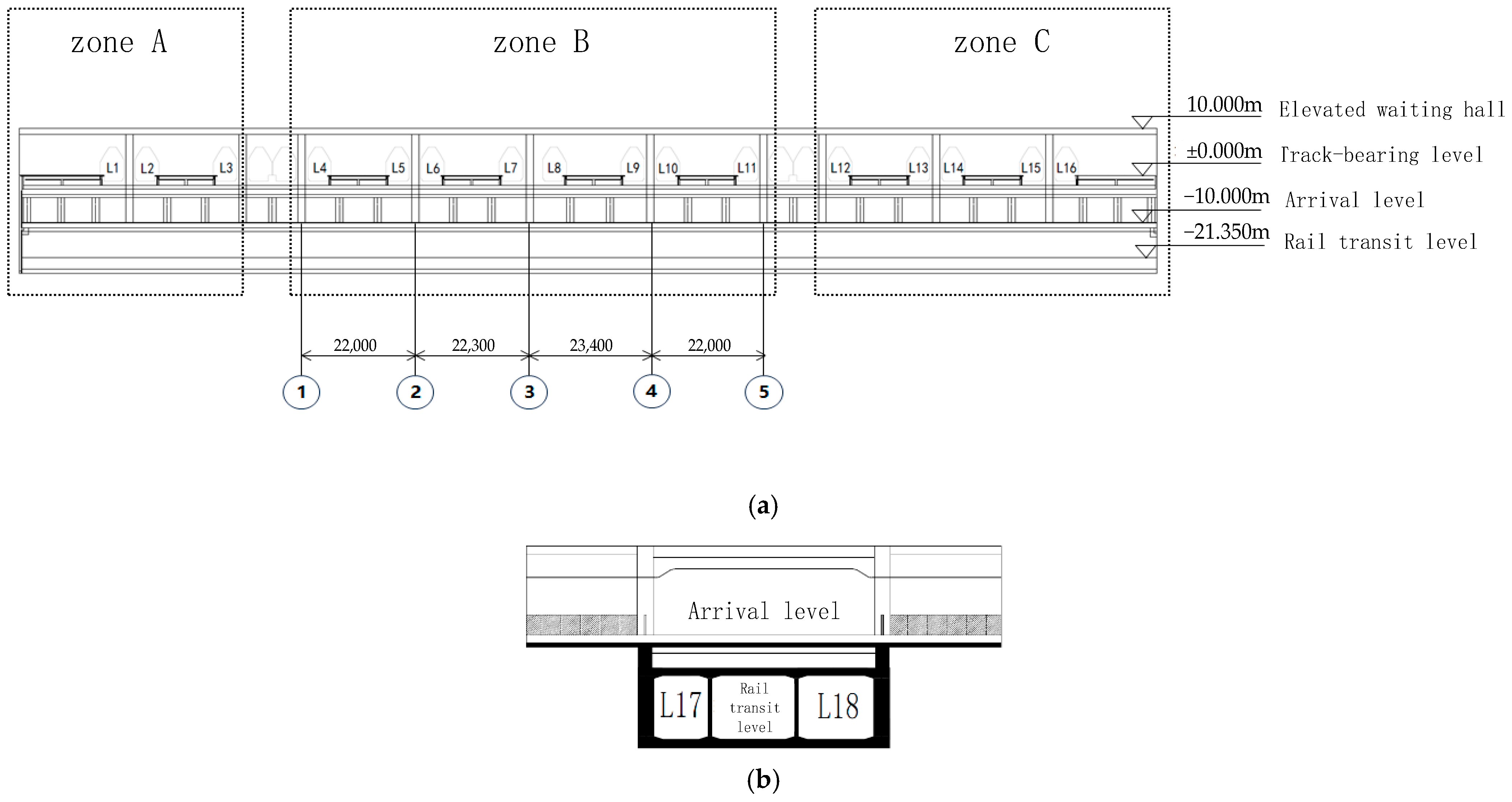
The station has a total construction area of 173,000 m2, with the main building occupying 80,000 m2. It features a layout of two underground and three above-ground levels, with plane dimensions of 240 m (longitudinal) × 332.7 m (transverse). The structural system consists of a large-span reinforced concrete frame supported by a natural foundation on moderately weathered rock, categorizing it as a complex structural system with ultra-large spans and heavy loads. The station is equipped with 9 platforms and 20 tracks, integrating various speed-level traffic lines: four 350 km/h HSR main lines, sixteen 80 km/h HSR arrival-departure tracks, and two 100 km/h subway lines. The subway lines are located on the second basement level (B2), while the HSR arrival hall and urban corridor are situated on the first basement level (B1), creating a multi-traffic flow coupled operational mode with three-dimensional connectivity. For analytical convenience, the HSR arrival-departure tracks are divided into three zones (A, B, and C) to support research on structural dynamics and train running performance. The schematic diagram of the station is shown in Figure 1.

2.2. Typical Calculation Scenarios

Based on the operational characteristics of Yichang North Station and the research objectives of this study, three typical calculation scenarios—single-line HSR operation, multi-line HSR operation, and collaborative HSR-subway operation—were selected for comparative analysis. This approach aims to systematically investigate the influence of different operational scenarios on the propagation of structural vibrations and to conduct targeted research on the vibration comfort of the elevated waiting hall floor.
The scenario settings are based on the actual track layout of the station, the distribution of which is illustrated in Figure 2. The HSR arrival-departure tracks are numbered L1–L16, and the subway lines are numbered L17–L18. The main-line bridge, which is separated from the station structure, divides the track-bearing floor into zones A, B, and C. Furthermore, two slab-hinged structural joints are set along the longitudinal direction of the elevated level to ensure that the zoning of the elevated structure corresponds to that of the track-bearing floor, thereby ensuring the precision of the scenario analysis.
Based on the aforementioned selection principles and structural layout, the three typical calculation scenarios are defined as follows: (1) Single-line HSR operation, representing the status of a single HSR arrival-departure track; (2) Multi-line HSR operation, simulating multiple tracks simultaneously handling high-speed passages; and (3) Collaborative HSR-subway operation, which focuses on the complex coupled state of synchronized HSR and subway operations. The details of the train configurations for each scenario are summarized in Table 1. Through a comparative analysis of the structural vibration responses across these scenarios, the propagation laws of vibrations under different traffic loads can be fully elucidated, providing a theoretical basis for optimizing vibration comfort in the elevated waiting hall.

3. Analysis Model of the Train-Track-Station Coupled System

3.1. Spatial Vibration Model of the Train

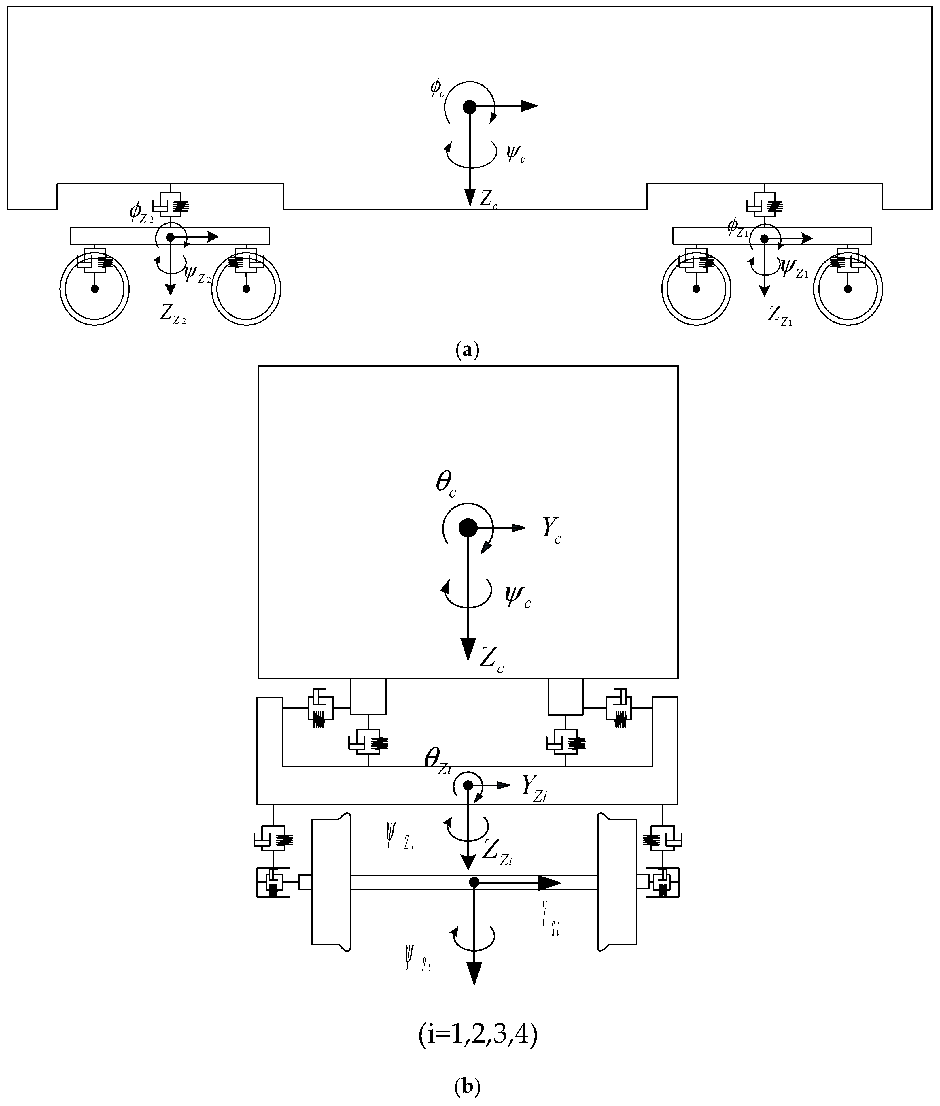
Given that both the CRH3 high-speed train and the Type-A subway train feature four-axle structural characteristics, an identical abstracted spatial dynamic modeling scheme is adopted for both, simplifying them into a 23-degree-of-freedom (23-DOF) four-axle vehicle dynamic model, as illustrated in Figure 3. To balance computational efficiency with engineering precision, the following reasonable assumptions are made during the modeling process: the car body, bogies, and wheelsets are treated as rigid bodies, and the longitudinal vibration of the car body and its associated coupling effects are neglected.
As shown in Figure 3, the generalized coordinates define the spatial movements of the vehicle components, where θ , ψ , and Z represent the pitching, yawing, and heaving motions of the car body ( c ), bogies ( t ), and wheelsets ( w ), respectively.
The distribution of degrees of freedom for this model is detailed in Table 2. Specifically, five DOFs—heaving, swaying, rolling, pitching, and yawing—are considered for the car body and each bogie frame. Each wheelset retains only two critical DOFs: swaying and yawing, resulting in a complete 23-DOF dynamic model. As the train travels across the track-bearing floor, its spatial position changes continuously throughout the operational process. By calculating the total potential energy of a single vehicle unit, the equations of motion for the vehicle system are derived based on fundamental principles of dynamics.
M v δ ¨ v + C v δ ˙ v + K v δ v = P v
where M v , C v , K v , and P v represent the mass matrix, damping matrix, stiffness matrix, and load vector of a single vehicle unit, respectively; δ ¨ v , δ ˙ v , and δ v denote the corresponding displacement, velocity, and acceleration vectors.

3.2. Selection of Track Irregularities

From the perspective of stochastic process characteristics, track irregularities for an infinite track can be approximated as an ergodic, weakly stationary process; however, for local track segments, the statistical characteristics vary with spatial position, exhibiting non-stationary behavior. In engineering practice, the power spectral density (PSD) function is the primary method for characterizing the statistical features of track irregularities, as it comprehensively reflects the energy distribution across different wavelengths. Referencing the authoritative recommendations in China’s “General Technical Conditions for High-Speed Trains” [40], this study adopts the German low-interference spectrum as the PSD function for track irregularities. The application of this specific spectrum is highly justified for the investigated Chinese HSR station conditions for two primary reasons. First, the station utilizes a modern, highly precise ballastless track system, and its exceptional geometric smoothness aligns perfectly with the physical characteristics represented by the German low-interference spectrum. Second, the CRH3 high-speed train model evaluated in this study is technologically derived from the German Velaro platform; thus, applying the German spectrum ensures theoretical consistency in the vehicle-track interaction modeling. Consequently, this spectrum provides reliable and realistic foundational data for the subsequent multi-source dynamic analyses.
Profile   irregularity :   S v ( Ω ) = A v Ω c 2 ( Ω r 2 + Ω 2 ) ( Ω c 2 + Ω 2 )
Alignment   irregularity :   S a ( Ω ) = A a Ω c 2 ( Ω r 2 + Ω 2 ) ( Ω c 2 + Ω 2 )
Cross-level   irregularity :   S c ( Ω ) = A v b 2 Ω c 2 Ω 2 ( Ω 2 + Ω r 2 ) ( Ω 2 + Ω c 2 ) ( Ω 2 + Ω s 2 )
Gauge   irregularity :   S g ( Ω ) = A g Ω c 2 Ω 2 ( Ω 2 + Ω r 2 ) ( Ω 2 + Ω c 2 ) ( Ω 2 + Ω s 2 )
where:
  • Ω is the Spatial frequency ( r a d / m ) .
  • Ω c and Ω r are the cut-off frequencies.
  • A v , A a , and A g are the roughness coefficients corresponding to profile, alignment, and gauge.
  • b—Half the distance between the left and right rolling circles (m), which can be taken as 0.75.
The specific cut-off frequencies and roughness coefficients are summarized in Table 3.
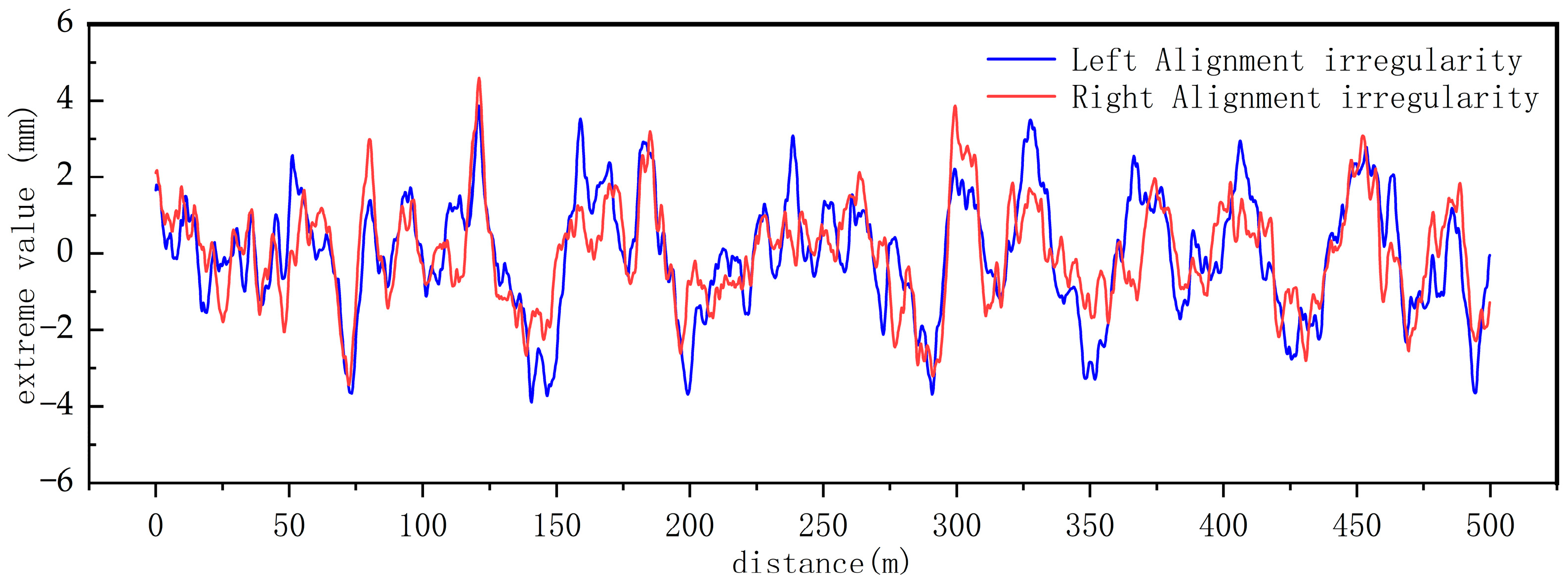
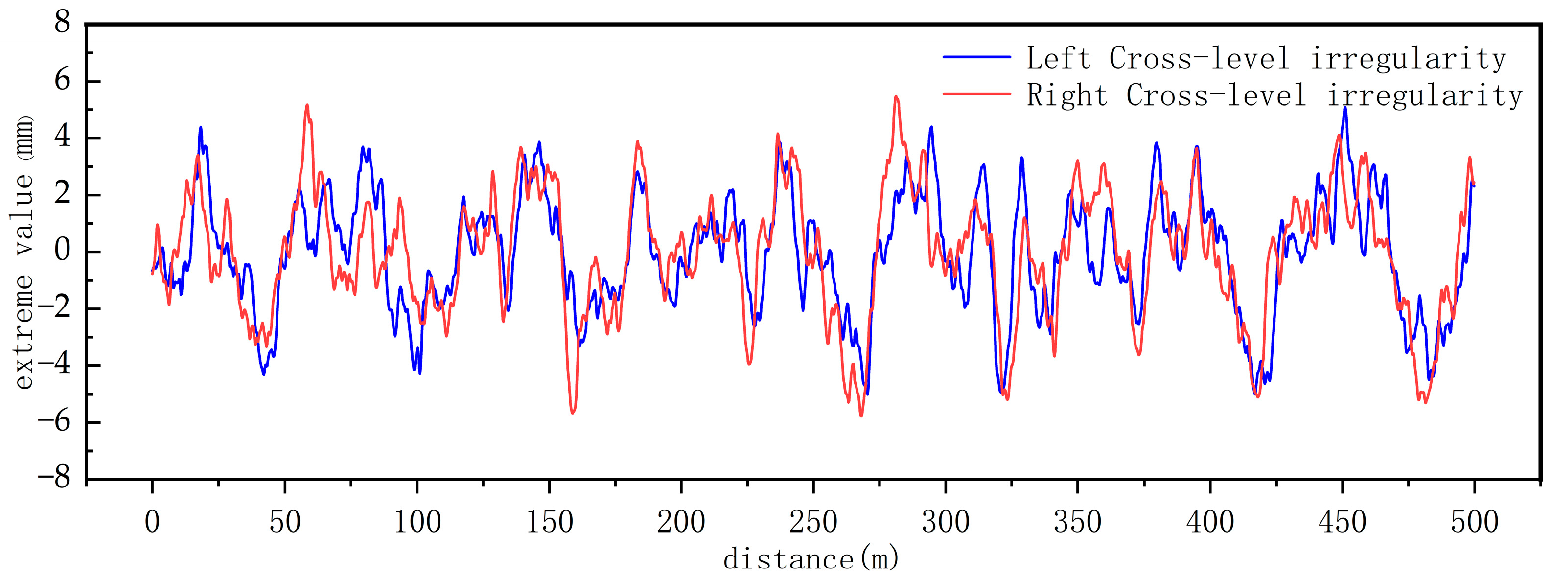
The time-domain track irregularities are generated using the German low-interference power spectral density function. The total length of the fitted time-domain irregularity is 500 m, with a sampling interval of 0.2 m. The fitting results are illustrated in Figure 4 and Figure 5.
As illustrated in Figure 4 and Figure 5, the time-domain track irregularity samples generated from the German low-interference spectrum exhibit distinct randomness and fluctuation in their spatial distribution, characterizing a stationary random process with a mean value tending towards zero. Specifically, the amplitudes of the alignment irregularities (Figure 4) are predominantly concentrated within the range of −4.0 mm to +4.5 mm. The irregularities of the left and right rails demonstrate a high degree of consistency in their overall macro-trends, yet they exhibit slight phase and amplitude differences at local peaks and troughs. This objectively reflects the uneven spatial deformation and independent mechanical behavior of actual left and right railway tracks.

3.3. Station Finite Element Simulation Model and Natural Vibration Characteristic Analysis

This study performs parametric modeling of the HSR station. Since vibrations in the roof structure under train excitation fall below control standards and have negligible impact on structural safety, refined modeling is restricted to the levels spanning from the rail transit level to the elevated level. To ensure the accuracy and reproducibility of the dynamic calculations, the finite element computational framework was established following rigorous structural dynamics principles.
During the modeling process, the structural beams and columns are simulated using 3D Timoshenko beam elements to account for shear deformations, while the floor slabs, basement walls, and shear walls are modeled with 4-node reduced-integration shell elements to mitigate potential shear locking. Based on a mesh sensitivity analysis, a generalized global element division strategy was adopted to accommodate the massive structural scale, with the characteristic element length generally controlled between 3 and 5 m. This discretization scale effectively balances computational efficiency with calculation accuracy.
The soil-structure interaction is also carefully considered. The pile foundations are modeled using the m-method, replacing actual piles with equivalent elastic spring elements configured with multi-directional stiffness matrices. Furthermore, elastic foundation plate elements are employed to model the box foundation baseplate, with constraints defined by the site-specific subgrade reaction coefficient, ensuring an accurate simulation of the foundation support.
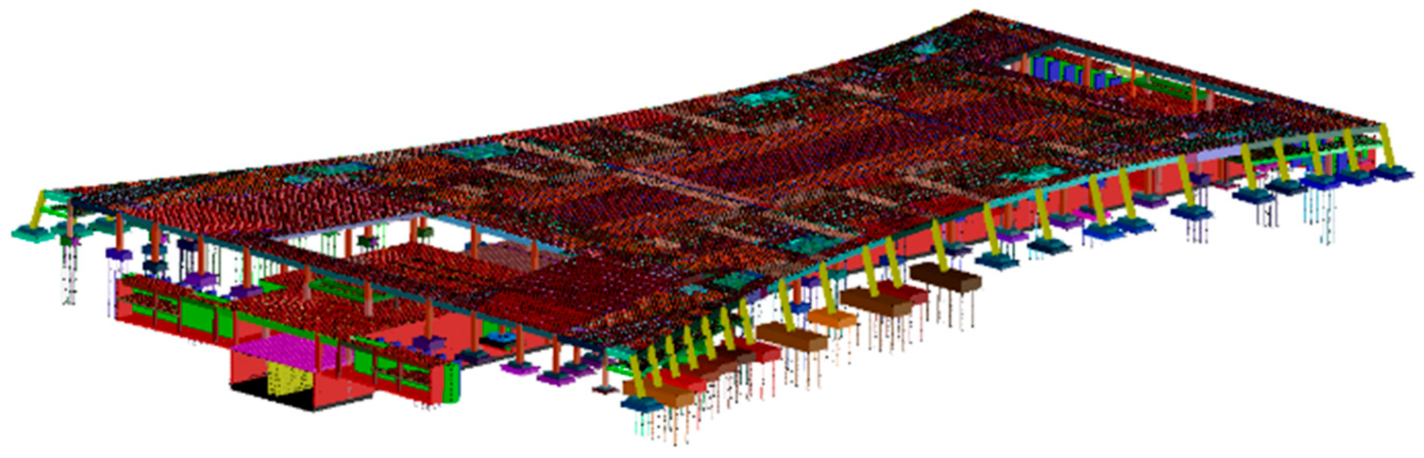
Structural energy dissipation is incorporated via the Rayleigh damping model ( C = α M + β K ). Assuming a 2% critical damping ratio typical for reinforced concrete structures, the proportionality coefficients α and β are determined based on the structure’s fundamental and dominant operational frequencies. The dynamic equations of the highly coupled train-track-station system are solved in the time domain using the unconditionally stable implicit Newmark- β method. To guarantee computational accuracy for high-frequency wheel-rail impact components, the integration time step Δ t is strictly set to 0.001 s. The constructed finite element model (FEM) of the station structure is shown in Figure 6. The material grades of the primary structural components are summarized in Table 4.
Based on the aforementioned track-station finite element model, the first 50 mode shapes of the structure were obtained through modal analysis. The analytical results, as summarized in Table 5, indicate that the stiffness distribution of the elevated floor is more non-uniform compared to other areas of the station, with its vertical vibrations dominated by local vibration modes.
It should be noted that the established 23-DOF spatial train model and the 3D finite element station model inherently compute comprehensive spatial dynamic behaviors, including horizontal vibrations, torsional/rolling effects, and low-frequency structural resonances (as reflected in the modal analysis). However, the results evaluation in this study focuses primarily on the vertical acceleration responses. This targeted focus was chosen because the massive vertical gravity loads of passing trains constitute the dominant excitation source in ISB structures, and the resulting vertical vibrations directly govern the threshold for passenger waiting comfort in the elevated halls.

3.4. Establishment of the Train-Track-Station Coupled Vibration Equations

This paper defines the train, track, and station (hereinafter collectively referred to as the “train-track-station” system) as a single coupled and time-varying holistic system. Regarding coordinate settings, the static equilibrium position of each independent structure is taken as the coordinate origin, and the boundary conditions of the station structure are directly assigned as the boundary conditions for this entire system. Through this approach, the inherently complex wheel-rail contact relationships are transformed into internal contact problems within the system. This transformation effectively avoids uncertainties, thereby ensuring that the vibration equations possess a unique solution [20].
Building on this, this paper further incorporates the interconnected characteristics of spatial vibration displacements between the vehicle and the station, calculating the total potential energy of the vehicle Π v t and the total potential energy of the track-station assembly Π b t , respectively, ultimately deriving the total potential energy of the train-track-station system at any given time t, Π d t . Subsequently, relying on the Principle of Total Potential Energy Invariance in elastic system dynamics δ Π d t = 0 , combined with the “rule of corresponding positions” in the matrix construction process, the vibration equations of the train-track-station system at time t can be established:
[ M ] { δ ¨ } + [ C ] { δ ˙ } + [ K ] { δ } = { P }
where [ M ] , [ C ] , and [ K ] represent the mass matrix, damping matrix, and stiffness matrix of the train-track-station system at time t, respectively; δ ¨ , δ ˙ , and δ correspond to the acceleration, velocity, and displacement vectors of the system at time t, respectively; and P denotes the load vector applied to the system at time t. This load vector consists of two components: the wheel-rail contact forces induced by track surface irregularities (encompassing both dynamic and static conditions), and the self-weight of the train.

4. Dynamic Response Analysis of Subway-Integrated Station Buildings Under Multi-Source Train Loads

4.1. Vertical Dynamic Response of the Structure Under Different HSR Train Speeds

To clarify the influence of train speed on the vibration response of the elevated level, this section selects the core arrival-departure track L7 based on the principles of operational representativeness and research specificity. Its track-structure coupling characteristics and dynamic transmission paths align with the research hypotheses, ensuring the effective transmission of vertical dynamic loads and maximizing the observable differences in vibration responses across various speeds.
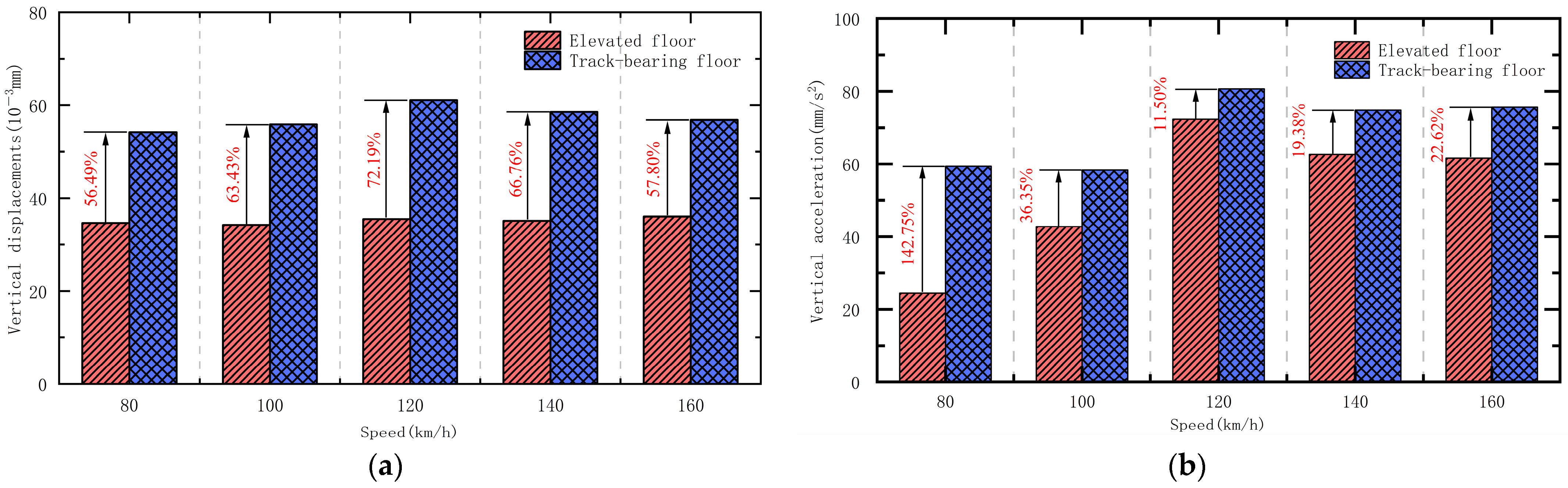
Guided by engineering practice and academic requirements, a design speed of 80 km/h for the arrival-departure track is selected as the baseline. Speeds of 100 km/h and 120 km/h are included to account for future upgrades, while 140 km/h and 160 km/h are selected for safety redundancy verification under extreme scenarios. Figure 7 presents the maximum vertical displacements and accelerations of the track-bearing floor and the elevated floor under each scenario.
As shown in Figure 7, regarding the vertical displacement response, the maximum vertical displacement of the track-bearing floor follows an “increase-then-decrease” trend as speed increases, peaking at 0.06 mm at 120 km/h. This value is well below the limit of “mid-span vertical deflection less than 1/700” specified in the Code for Design of Railway Bridges and Culverts, confirming that the structural deformation meets safety requirements. The percentage difference in displacement between the track-bearing and elevated levels also shows an “increase-then-decrease” trend, reaching 41.92% at 120 km/h. Within the 80–160 km/h range, the maximum vertical displacement of the elevated floor exhibits a minimal rate of change, indicating that it is insignificantly affected by train speed and possesses excellent structural stability. Regarding the vertical acceleration response, the peak vertical acceleration of the elevated floor is 72.34 mm/s2 (approximately 0.007 g). The percentage difference in acceleration displays a characteristic “sharp decline followed by a slight rebound,” dropping from 142.75% at 80 km/h to 11.50% at 120 km/h. This phenomenon is attributed to the significant increase in acceleration of the elevated level at 120 km/h due to structural resonance effects. Specifically, the 120 km/h speed induces primary excitation frequencies that closely align with the local vertical natural bending frequencies of the elevated floor slabs in specific zones. As identified in Table 5, these structural natural frequencies range from approximately 6.9 Hz to 8.2 Hz, and the matching train-induced excitations at this speed thereby trigger localized resonance amplification. According to the AISC-11 standard [37], the acceleration responses satisfy the requirements for human vibration comfort.

4.2. Vertical Dynamic Response Under Parallel Multi-Line HSR Operation

To determine the distribution laws of the vertical dynamic responses at the elevated level of a large-scale integrated station-bridge HSR station jointly constructed with a subway under busy multi-line operational conditions, a targeted analysis was conducted based on actual engineering conditions. Due to the vibration isolation effect of the main-line bridge, vibrations generated by trains operating solely in Zone B are unlikely to propagate to Zones A and C. Therefore, Scenario 2 in Table 1 was selected as the calculation scenario to study the dynamic responses specifically under multi-line operations in Zone B. This specifically focuses on the eight tracks L4–L11 in Zone B, with the parallel running speed of the trains set at 80 km/h according to the design speed of the arrival-departure tracks.
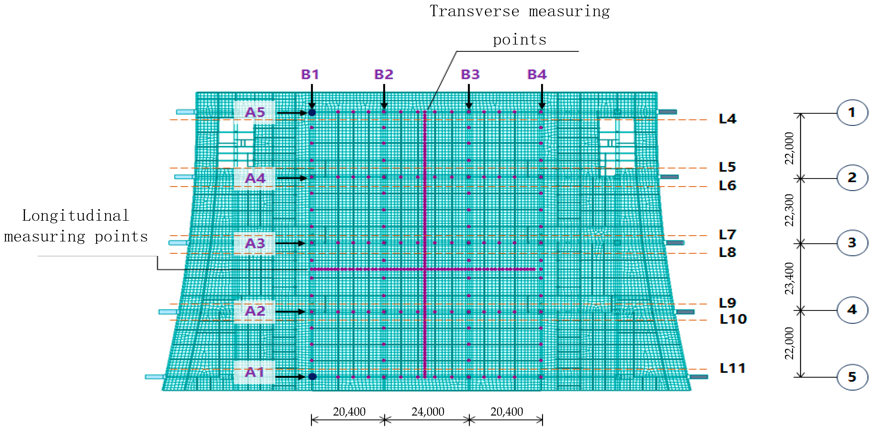
Train-induced vibrations generated during train passages directly affect the comfort of passengers in the elevated waiting hall. To precisely reveal the spatial distribution characteristics of the dynamic responses on the elevated level, measuring points were preferentially arranged at key locations with relatively weak structural mechanical performance, based on the distribution laws of the structural column grid in Zone B. The specific layout of the measuring points is shown in Figure 8. The distribution covers the core area of the column grid in Zone B. Among them, the longitudinal measuring lines are A1–A5, selecting the column top nodes and secondary beam nodes in the longitudinal direction as measuring points; the transverse measuring lines are B1–B4, selecting the column top nodes and secondary beam nodes in the transverse direction as measuring points. For the mid-span measuring lines, the starting point of the transverse mid-span is located 12 m to the right of node 1 in column B2, with one measuring point deployed every 1 m along the transverse mid-span; the starting point of the longitudinal mid-span is located 9 m below measuring point 1 in row A3, with one measuring point deployed every 1 m along the longitudinal mid-span. The variation laws of the dynamic responses obtained from the current calculations for each measuring point are summarized in Figure 8.
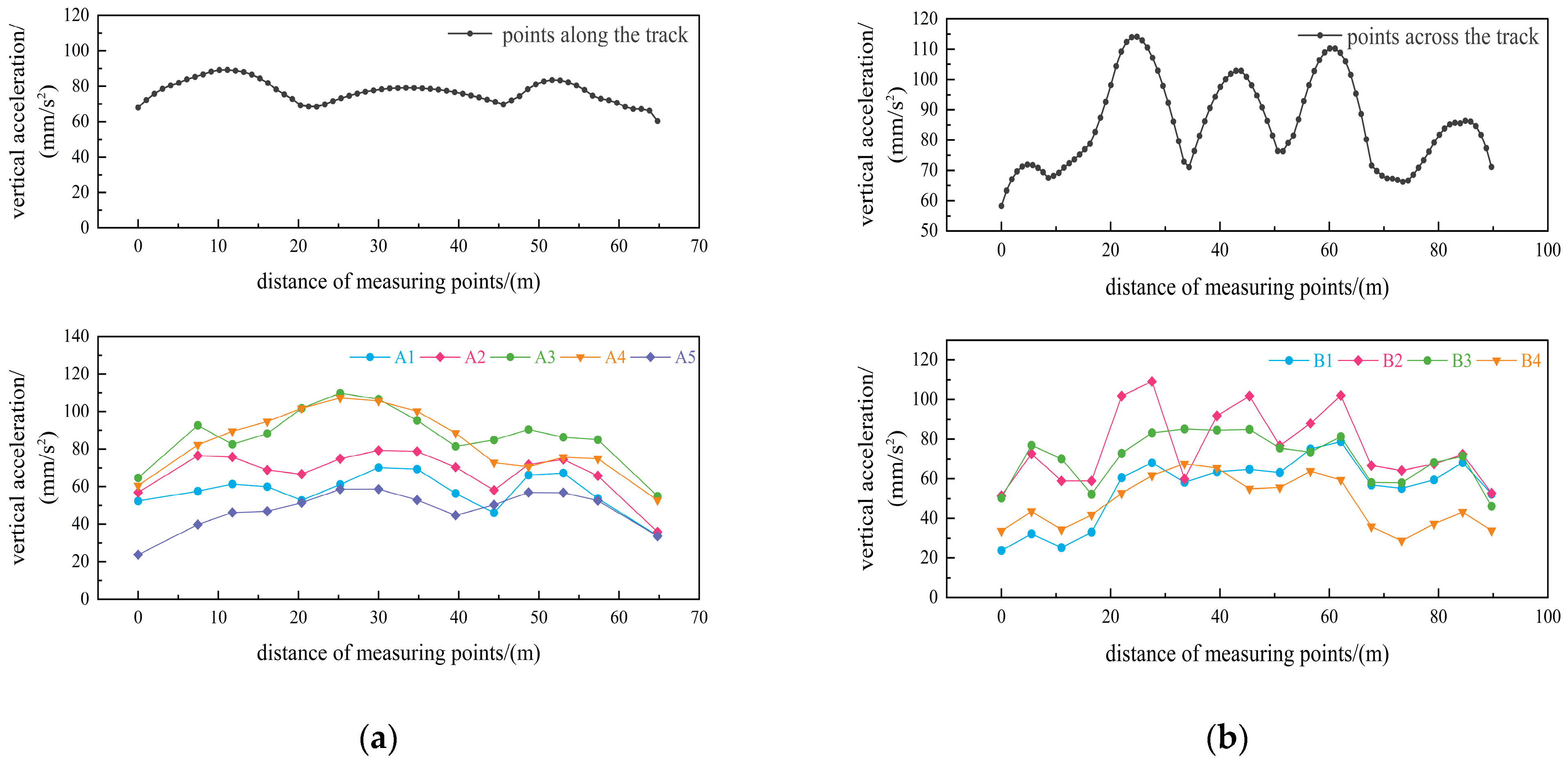
As shown in Figure 9, under the eight-line operational scenario, train vibrations are transmitted from the platform level through the column system to the column tops of the elevated level, and further propagate along the beam-slab system. In the longitudinal dimension, the vertical acceleration curves exhibit distinct peaks at the beam mid-span regions (near distances of 10 m and 50 m) and troughs at the frame columns (near 20 m and 40 m) due to sudden changes in stiffness. This is consistent with the characteristics of flexural vibration, where the mid-span deflection is large and the dynamic response is significant. Furthermore, the differences in response amplitudes among various longitudinal measuring points along A1–A5 further corroborate the dynamic propagation law of “amplification at the mid-span and attenuation at the column ends when vibrations are transmitted along beams.” In the transverse dimension, the distribution of acceleration peaks corresponds highly with the spatial positions of the arrival-departure tracks, specifically reflected in the regions near measuring point distances of 20 m, 40 m, 60 m, and 80 m. Under multi-line operation, the peaks of the transverse measuring points along B1–B4 superimpose in the corresponding regions. This results from the superposition effect of dynamic responses generated by vibration excitations from multiple arrival-departure tracks at the same structural location. In summary, through a systematic analysis of the longitudinal and transverse vibration responses, this study reveals the intrinsic correlation between the distribution laws of the vertical acceleration responses at the elevated level and the structural mechanical characteristics (the differences in beam-column dynamic characteristics), as well as the layout features (the number and spatial positions of the arrival-departure tracks). Namely, the longitudinal direction follows the beam vibration law of “mid-span amplification and column-site attenuation,” while the transverse direction presents the distribution feature of “superposition and amplification of multi-line excitations directly above the arrival-departure tracks.” Together, these elucidate the “track-column-beam-slab” transmission path of train vibrations in the elevated structure and the dynamic response mechanism of “mid-span amplification and multi-line superposition.”

4.3. Vertical Dynamic Response Under Combined HSR and Subway Effects

To investigate the influence of subway operations on the dynamic response of the elevated station structure, Scenarios 3 and 4 from Table 1 were selected for calculation, representing the single-line subway L17 operational scenario and the double-line L17–L18 operational scenario, respectively, both at a running speed of 100 km/h. The calculated maximum vertical dynamic responses of the elevated floor are summarized in Table 6.
As shown in Table 6, because the elevated station structure is not directly erected above the subway track-bearing level and does not directly sustain the subway train dynamic loads, the maximum vertical acceleration of the elevated level is only 38.35 mm/s2 (approximately 0.004 g), even under double-track subway operation, which is far below the 0.015 g limit specified by the AISC-11 standard [37]. From the trend of the response variations, it is evident that as the number of operating trains increases, the vertical displacement and acceleration responses of the elevated level exhibit characteristics of superimposed augmentation.
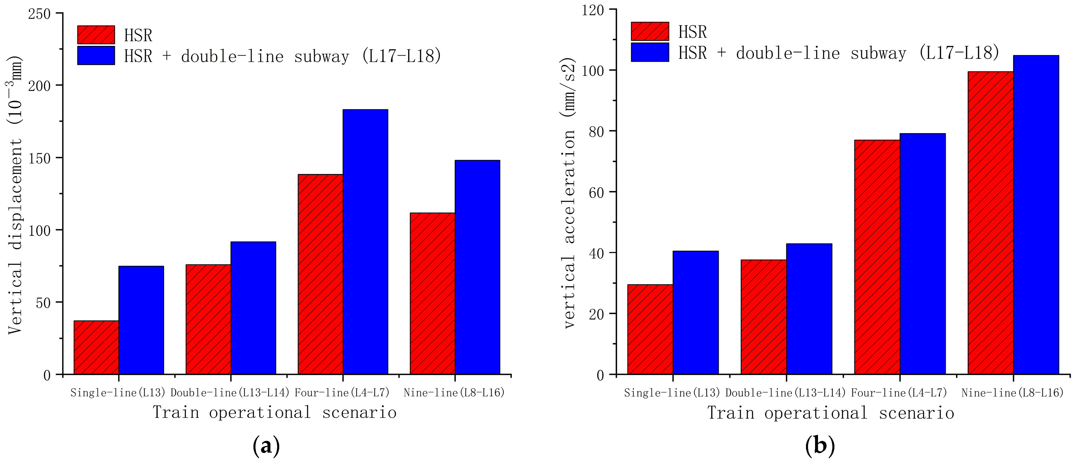
Considering that subway and HSR trains may operate synergistically in actual practice, to further explore the influence of their coupled effects on the dynamic response of the station structure, this section selects typical HSR operational scenarios of single-line, double-line, four-line, and nine-line, as well as scenarios where HSR and subway trains act concurrently, for comparative analysis of the calculation results. The running speed of the HSR for all lines is 80 km/h, and the comparison results are summarized in Figure 10.
As shown in Figure 10, under the common operational scenarios of this station, when the dynamic loads of subway and HSR trains act simultaneously, the increment in the vertical dynamic response of the elevated level is generally small compared to the effects of HSR trains acting alone. Specifically, under four typical scenarios—single-line L13, double-line L13–L14, four-line L4–L7, and nine-line L8–L16—the incremental increases in the maximum vertical acceleration of the elevated level are 37.3%, 14.3%, 2.7%, and 5.4%, respectively. It is worth noting that as the number of operational HSR lines increases, the increment in the additional vibration response caused by the subway exhibits an overall diminishing trend. This phenomenon suggests that in the context of multi-line HSR operations, the overall structural stiffness of the system is enhanced or the vibration response tends toward “saturation,” thereby relatively weakening the additional dynamic influence brought by subway operations. This indicates that the vibration environment dominated by the HSR exerts greater control over the structural response. Therefore, in the vibration assessment and structural design of similar large-scale transportation hubs, primary consideration should be given to the vibration effects of HSR operations, while the amplification effects of vibrations caused solely by the subway can be appropriately de-emphasized in the design of HSR-subway co-constructed sections.

5. Conclusions

The current literature underscores a critical knowledge gap in the dynamic assessment of modern transportation mega-hubs: the synergistic superposition mechanisms of multi-source train excitations remain insufficiently quantified. Although previous studies have extensively investigated vibrations induced by isolated high-speed railway (HSR) or subway operations, they generally fail to capture the complex, multi-level structural interactions intrinsic to integrated station-bridge (ISB) systems. To address this deficiency, this study established a refined three-dimensional (3D) train-track-station spatially coupled dynamic model. This model yields a quantitative framework for evaluating the transmission, superposition, and attenuation mechanisms of concurrent HSR and subway operational loads.
The primary contributions and technical advantages of this research are delineated as follows:
(1)
Characterization of Cross-Level Energy Transmission: Diverging from conventional single-source analytical models, the proposed framework successfully delineates the three-dimensional propagation pathways of vibration energy across distinct structural hierarchies within a complex frame structural system.
(2)
Identification of Localized Dynamic Vulnerabilities: The developed model accurately captures critical structural dynamic behaviors under realistic operational scenarios, particularly highlighting localized dynamic amplifications at beam mid-spans and resonance tendencies near the 120 km/h operational speed.
(3)
Elucidation of Multi-Source Superposition Mechanisms: This investigation quantitatively demonstrates that under concurrent multi-line HSR traffic, the additional vibration contribution from subway operations diminishes significantly. This “response saturation” phenomenon provides a rigorous theoretical basis for optimizing vibration control and structural design in multi-tiered co-constructed hubs.
Despite these advancements, the authors acknowledge specific limitations inherent to this numerical investigation. Primarily, the operational scenarios were simulated utilizing ideal train-running parameters and assuming linear-elastic structural behavior. Consequently, potential dynamic amplifications arising from non-linear material degradation under extreme loading, intricate soil-structure interactions, discrete wheel defects, or progressive track deterioration were not incorporated into the current scope. Furthermore, while the formulated 23-DOF spatial vehicle model and 3D finite element station model inherently compute multi-directional spatial responses—including lateral swaying and torsional effects—the present evaluation is strictly confined to vertical serviceability limits. Although vertical gravity loads constitute the dominant excitation source affecting floor comfort in ISB structures, lateral vibrations and structure-borne noise represent supplementary dimensions of passenger serviceability that warrant systematic investigation.
To address these limitations and propel future development, subsequent research will prioritize the integration of advanced Structural Health Monitoring (SHM) paradigms. A pivotal future objective involves updating and validating the proposed numerical model using empirical drive-by monitoring data and long-term in-situ vibration measurements from the operational station. Expanding the computational framework to encompass non-linear material parameters, multi-dimensional vibration assessments, and structure-borne noise predictions will ultimately yield a more robust and comprehensive safety and comfort evaluation system for next-generation integrated transportation hubs.

Author Contributions

Conceptualization, X.G. and J.L.; methodology, J.L. and C.L.; software, Y.X. and C.L.; validation, J.L., Y.X. and D.Z.; formal analysis, J.L.; investigation, Y.X.; resources, D.Z. and X.G.; data curation, C.L.; writing—original draft preparation, J.L.; writing—review and editing, X.G. and D.Z.; visualization, Y.X.; supervision, X.G.; project administration, X.G.; funding acquisition, X.G. and D.Z. All authors have read and agreed to the published version of the manuscript.

Funding

This research received no external funding.

Data Availability Statement

The original contributions presented in the study are included in the article, further inquiries can be directed to the corresponding author.

Acknowledgments

During the preparation of this manuscript, the authors used Gemini 3.0 for the purposes of language translation, grammar correction, and text refinement. The authors have reviewed and edited the output and take full responsibility for the content of this publication.

Conflicts of Interest

Author Deliang Zhou was employed by the company Central–South Architectural Design Institute Co., Ltd. The remaining authors declare that the research was conducted in the absence of any commercial or financial relationships that could be construed as a potential conflict of interest.

References

  1. Xu, S.; Xu, Q.; Zhu, Y.; Guan, Z.; Wang, Z.; Fan, H. Dynamic Response of Bridge-Tunnel Overlapping Structures under High-Speed Railway and Subway Train Loads. Sustainability 2024, 16, 848. [Google Scholar] [CrossRef]
  2. Yang, N.; Guo, T.; Sun, G. Train-Induced Vibration on Elevated Railway Station. J. Cent. South Univ. 2013, 20, 3745–3753. [Google Scholar] [CrossRef]
  3. Guo, X.; Liu, J.; Cui, R. Research on Train-Induced Vibration of High-Speed Railway Station with Different Structural Forms. Materials 2024, 17, 4387. [Google Scholar] [CrossRef]
  4. Dan, D.; Wang, W.; Luo, M.; Zhao, Y. Online Traffic Load Identification of High-Speed Railway Bridge Using Time Integration of Strain Monitoring Data. Measurement 2026, 269, 120781. [Google Scholar] [CrossRef]
  5. Tran, M.; Cam Nhung, N.T.; Van, T.N.; Komarizadehasl, S. Innovative Experimental Assessment of Direct and Drive-by Monitoring on Two Truss Bridges. Measurement 2026, 278, 121693. [Google Scholar] [CrossRef]
  6. Sun, H.; Peng, X.; Xu, J.; Tu, H. Identification of Moving Train Axle Loads for Simply Supported Composite Beam Bridges in Urban Rail Transit. Appl. Sci. 2024, 14, 8310. [Google Scholar] [CrossRef]
  7. Minh, T.Q.; Ngo Van, T.; Nguyen, H.X.; Nguyễn, Q. Enhancing the Structural Health Monitoring (SHM) through Data Reconstruction: Integrating 1D Convolutional Neural Networks (1DCNN) with Bidirectional Long Short-Term Memory Networks (Bi-LSTM). Eng. Struct. 2025, 340, 120767. [Google Scholar] [CrossRef]
  8. Wang, W.; Dan, D.; Gao, J. Study on Damage Identification of High-Speed Railway Truss Bridge Based on Statistical Steady-State Strain Characteristic Function. Eng. Struct. 2023, 294, 116723. [Google Scholar] [CrossRef]
  9. Du, L.; Zhang, J. Vibro-Energy Transmission in Box-Girders: Dynamic Coupling Effects Induced by High-Speed Train Loads. J. Mech. Sci. Technol. 2025, 39, 6593–6600. [Google Scholar] [CrossRef]
  10. Wang, Y.-W.; Ni, Y.-Q.; Wang, S.-M. Structural Health Monitoring of Railway Bridges Using Innovative Sensing Technologies and Machine Learning Algorithms: A Concise Review. Intell. Transp. Infrastruct. 2022, 1, liac009. [Google Scholar] [CrossRef]
  11. Koç, M. A New Expert System for Active Vibration Control (AVC) for High-Speed Train Moving on a Flexible Structure and PID Optimization Using MOGA and NSGA-II Algorithms. J. Braz. Soc. Mech. Sci. Eng. 2022, 44, 151. [Google Scholar] [CrossRef]
  12. Liu, L.; Zuo, Z.; Yau, J.D.; Urushadze, S. A Simplified Method to Assess Vehicle–Bridge Interaction for Train-Induced Vibration of Light-Weight Railway Bridges. J. Chin. Inst. Eng. 2022, 45, 651–660. [Google Scholar] [CrossRef]
  13. Zhao, C.; Liu, D.; Zhang, X.; Yi, Q.; Wang, L.; Wang, P. Influence of Vibration Isolator Failure on Vehicle Operation Performance and Floating Slab Track Structure Vibration Reduction Effectiveness. Shock Vib. 2019, 2019, 8385310. [Google Scholar] [CrossRef]
  14. Gou, H.; Gao, H.; Ban, X.; Meng, X.; Bao, Y. Vibration Energy Transmission in High-Speed Train-Track-Bridge Coupled Systems. Eng. Struct. 2023, 297, 117019. [Google Scholar] [CrossRef]
  15. Qiu, Y.; Zou, C.; Wu, J.; Shen, Z.; Zhong, Z. Building Vibration Measurements Induced by Train Operation on Concrete Floor. Constr. Build. Mater. 2023, 394, 132283. [Google Scholar] [CrossRef]
  16. Hu, J.; Zou, C.; Liu, Q.; Li, X.; Tao, Z. Floor Vibration Predictions Based on Train-Track-Building Coupling Model. J. Build. Eng. 2024, 89, 109340. [Google Scholar] [CrossRef]
  17. Guo, X.; Wang, S. Research on the Dynamic Response of the Multi-Line Elevated Station with “Integral Station-Bridge System”. Buildings 2024, 14, 758. [Google Scholar] [CrossRef]
  18. Di, G.; Xie, Z.; Guo, J. Predict the Influence of Environmental Vibration from High-Speed Railway on Over-Track Buildings. Sustainability 2021, 13, 3218. [Google Scholar] [CrossRef]
  19. Wang, C.; Wang, J.; Chen, H.; Ou, J. Mitigating Train-Induced Building Vibrations with Rubber Bearings Designed for Horizontal Earthquake Isolation. J. Build. Eng. 2024, 89, 109251. [Google Scholar] [CrossRef]
  20. Zhou, R.; Yang, F.; Liu, H.; Xu, J.; Feng, Q.; Li, S. Vibration Transmission of Ballastless Track-Bridge with Different Span Lengths under Updated High-Speed Trains. KSCE J. Civ. Eng. 2024, 28, 3913–3927. [Google Scholar] [CrossRef]
  21. Zhu, Z.; Davidson, M.; Harik, I.; Yu, Z. Train-Induced Vibration Characteristics of an Integrated High-Speed Railway Station. J. Perform. Constr. Facil. 2017, 31, 04017010. [Google Scholar] [CrossRef]
  22. Yuan, W.; Jia, B.; Zhou, Z.; Zhang, J.; An, P. A Multi-Parameters Assessment Method and Prediction Model for Ground Vibration under the High-Speed Railway Bridge. Sci. Rep. 2025, 15, 10344. [Google Scholar] [CrossRef]
  23. Ma, M.; Xu, L.; Du, L.; Wu, Z.; Tan, X. Prediction of Building Vibration Induced by Metro Trains Running in a Curved Tunnel. J. Vib. Control 2021, 27, 515–528. [Google Scholar] [CrossRef]
  24. Chen, Y.; Feng, Q.; Liu, Q.; Jiang, J. Experimental Study on the Characteristics of Train-Induced Vibration in a New Structure of Metro Depot. Environ. Sci. Pollut. Res. 2021, 28, 41407–41422. [Google Scholar] [CrossRef]
  25. Zhang, W.; Song, K.; Kang, K.; Lee, D. Numerical Analysis of Vibration Standard Conditions of Adjacent Buildings Caused by Subway Train. KSCE J. Civ. Eng. 2025, 29, 100114. [Google Scholar] [CrossRef]
  26. He, C.; Zhou, S.; Di, H.; Zhang, X. An Efficient Prediction Model for Vibrations Induced by Underground Railway Traffic and Experimental Validation. Transp. Geotech. 2021, 31, 100646. [Google Scholar] [CrossRef]
  27. Liu, W.; Li, C.; Ma, L.; Du, L. A Frequency-Domain Formulation for Predicting Ground-Borne Vibration Induced by Underground Train on Curved Track. J. Sound Vib. 2023, 549, 117578. [Google Scholar] [CrossRef]
  28. Guo, T.; Zhi, G.; Zhu, R.; Zhang, L. Train-Induced Vibration Characteristics of a Double-Story High-Speed Railway Station. J. Perform. Constr. Facil. 2024, 38, 04024008. [Google Scholar] [CrossRef]
  29. Wu, Q.; Zhang, Q.; Sun, J.; Chen, X.; Xie, W. Research on Vibration Response and Vibration Attenuation Model of Comprehensive Transportation Hub under Multiple-Source Excitations. Earthq. Eng. Eng. Vib. 2025, 24, 527–545. [Google Scholar] [CrossRef]
  30. Chen, Z.; Peng, S.; Xu, H.; Yin, Q.; Zhou, J. Experiment and Analysis of Train-Induced Metro Depot Vibration. Int. J. Rail Transp. 2025, 13, 557–577. [Google Scholar] [CrossRef]
  31. Liang, R.; Ding, D.; Liu, W.; Sun, F.; Cheng, Y. Experimental Study of the Source and Transmission Characteristics of Train-Induced Vibration in the over-Track Building in a Metro Depot. J. Vib. Control 2023, 29, 1738–1751. [Google Scholar] [CrossRef]
  32. Matsuoka, K.; Kaito, K.; Sogabe, M. Bayesian Time–Frequency Analysis of the Vehicle–Bridge Dynamic Interaction Effect on Simple-Supported Resonant Railway Bridges. Mech. Syst. Signal Process. 2020, 135, 106373. [Google Scholar] [CrossRef]
  33. Jiang, L.; Peng, K.; Zhou, W.; Yu, J. Study on the Seismic Influence Coefficient of Track Irregularity on the Train Dynamic Effect of High-Speed Railway Bridge. Mech. Based Des. Struct. Mach. 2024, 52, 3339–3357. [Google Scholar] [CrossRef]
  34. Zhou, Z.; Jia, B.; Yuan, W.; Zhang, J. Vibration Response Prediction and Vibration Safety Assessment Method for Building Structures around Viaducts under the Action of High-Speed Railway Trains. Constr. Build. Mater. 2024, 422, 135877. [Google Scholar] [CrossRef]
  35. Cao, R.; Ma, M.; Sun, X.; Chen, J. Transmission Characteristics of Train-Induced Vibration in Buildings Based on Wave Propagation Analysis. Constr. Build. Mater. 2023, 378, 131154. [Google Scholar] [CrossRef]
  36. Tao, Z.; Wang, Y.; Sanayei, M.; Moore, J.; Zou, C. Experimental Study of Train-Induced Vibration in over-Track Buildings in a Metro Depot. Eng. Struct. 2019, 198, 109473. [Google Scholar] [CrossRef]
  37. Murray, T. Floor Vibrations Due to Human Activity (AISC Design Guide 11); AISC: Chicago, IL, USA, 2016. [Google Scholar]
  38. Liu, Q.; Li, X.; Zhang, X.; Zhou, Y.; Chen, Y.F. Applying Constrained Layer Damping to Reduce Vibration and Noise from a Steel-Concrete Composite Bridge: An Experimental and Numerical Investigation. J. Sandw. Struct. Mater. 2020, 22, 1743–1769. [Google Scholar] [CrossRef]
  39. Tao, Z.; Hu, Z.; Wu, G.; Huang, C.; Zou, C.; Ying, Z. Train-Induced Vibration Predictions Based on Data-Driven Cascaded State-Space Model. Buildings 2022, 12, 114. [Google Scholar] [CrossRef]
  40. TB 10621-2014; Code for Design of High Speed Railway. National Railway Administration of the People’s Republic of China Date: Beijing, China, 2014.
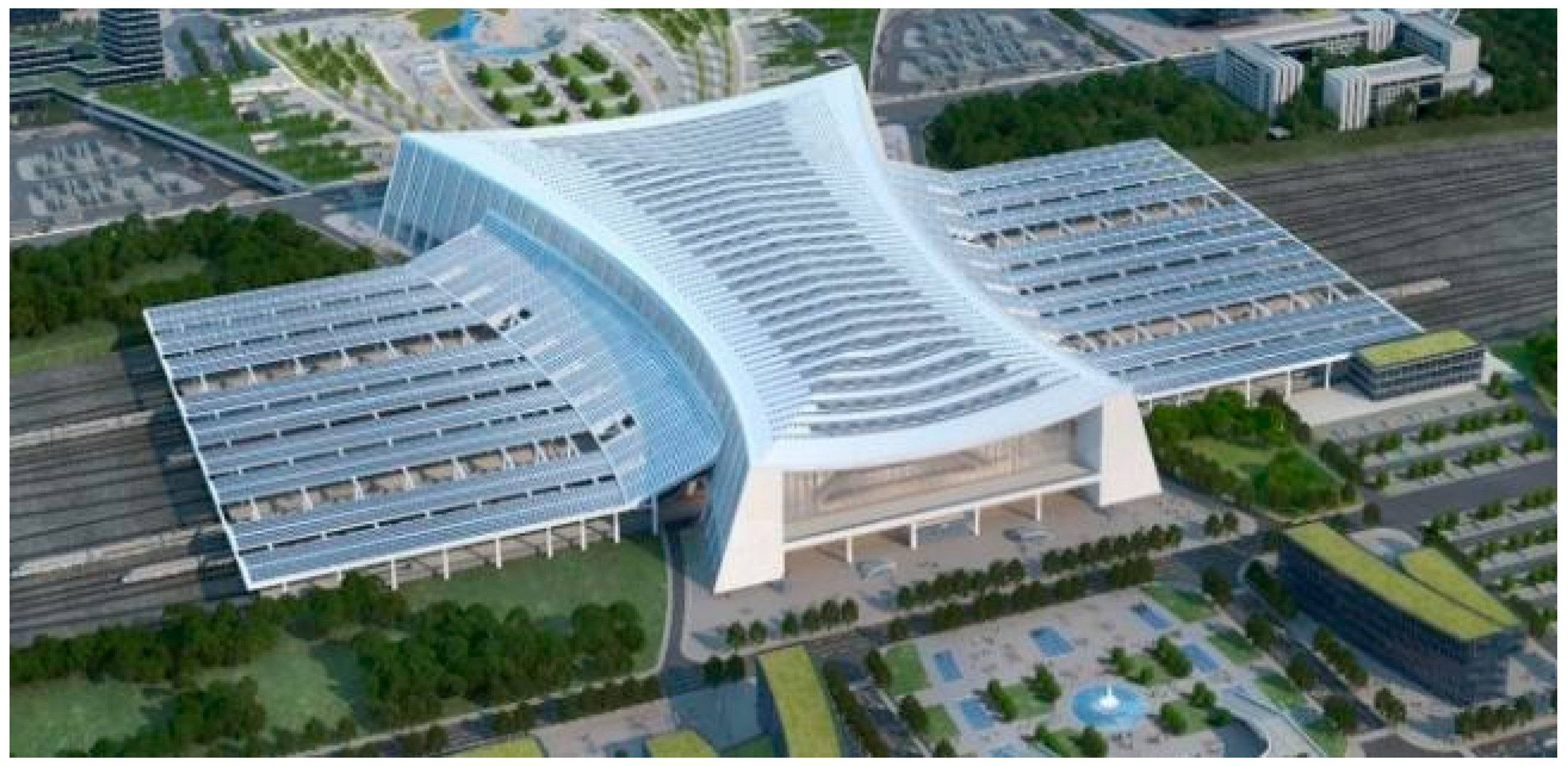
Figure 1. Schematic diagram of the Yichang North Railway Station.
Buildings 16 02304 g001
Figure 2. Distribution of railway tracks in the station. (a) Distribution of HSR tracks. (b) Distribution of subway tracks.
Buildings 16 02304 g002
Figure 3. Schematic diagram of the degrees of freedom (DOFs) for the four-axle vehicle model. (a) Elevation view of the vehicle model. (b) Cross-sectional view of the vehicle model.
Buildings 16 02304 g003
Figure 4. Alignment track irregularities.
Buildings 16 02304 g004
Figure 5. Cross-level track irregularities.
Buildings 16 02304 g005
Figure 6. Finite element model of the station.
Buildings 16 02304 g006
Figure 7. Maximum vertical dynamic responses of the track-bearing floor and elevated floor under different train speeds. (a) Vertical displacements of the structure under different train speeds. (b) Vertical accelerations of the structure under different train speeds.
Buildings 16 02304 g007
Figure 8. Schematic layout of measuring points in Zone B of the station structure (cm).
Buildings 16 02304 g008
Figure 9. Distribution of vertical accelerations at measuring points on the elevated level under the L4–L11 operational scenario at a speed of 80 km/h. (a) Distribution of maximum vertical accelerations at longitudinal measuring points. (b) Distribution of maximum vertical accelerations at transverse measuring points.
Buildings 16 02304 g009
Figure 10. Vertical vibration responses of the elevated level under combined HSR and subway operational scenarios. (a) Vertical displacement responses of the elevated level structure. (b) Vertical acceleration responses of the elevated level structure.
Buildings 16 02304 g010
Table 1. Summary of typical operational scenarios.
NoTrain TypeSpeed (km/h)Operational ScenarioTrack Number
1CRH380, 100, 120, 140, 160Single-line HSRL7
2CRH380Eight-line HSRL4–L11
3Type-A subway train100Single-line HSRL17
4Type-A subway train100Double-line subwayL17–L18
5CRH3
Type-A subway train
80 (CRH3)
100 (Type-A subway train)
Single-line HSR + Double-line subwayL13 + L17–L18
6CRH3
Type-A subway train
80 (CRH3)
100 (Type-A subway train)
Double-line HSR + Double-line subwayL13–L14 + L17–L18
7CRH3
Type-A subway train
80 (CRH3)
100 (Type-A subway train)
Four-line HSR + Double-line subwayL4–L7 + L17–L18
8CRH3
Type-A subway train
80 (CRH3)
100 (Type-A subway train)
Nine-line HSR + Double-line subwayL8–L16 + L17–L18
Table 2. Components of degrees of freedom for the four-axle vehicle model.
ComponentPitchingRollingHeavingSwayingYawing
Car body ϕ c θ c Z c Y c ψ c
Front bogie frame ϕ Z 1 θ Z 1 Z Z 1 Y Z 1 ψ Z 1
Rear bogie frame ϕ Z 2 θ Z 2 Z Z 2 Y Z 2 ψ Z 2
Wheelsets 1–4/// Y S i ψ S i
Table 3. Cut-off Frequency and Roughness Coefficient.
Ω c   ( r a d / m ) Ω r   ( r a d / m ) Ω s   ( r a d / m ) A a   ( r a d · m ) A v   ( r a d · m ) A g   ( r a d · m )
0.8246 0.0206 0.4380 2.119 × 10 7 4.032 × 10 7 0.532 × 10 7
Table 4. Material grades of the primary structural components.
ComponentMaterial GradeElastic Modulus (N·mm−2)
Beams, columns, and slabs on the arrival levelC403.25 × 104
Beams on the track-bearing levelC503.45 × 104
Columns and slabs on the track-bearing levelC403.25 × 104
Beams, columns, and slabs on the elevated levelC403.25 × 104
Table 5. Natural vibration frequencies of the station model.
Mode OrderNatural Frequency/HzNatural Period/sMode Shape Characteristics of the Elevated Floor Slabs
266.9200.145Vertical bending of slabs in Zone C
327.7040.130Vertical bending of slabs in Zone A
408.2370.121Vertical bending of slabs in Zone B
Table 6. Vertical vibration responses of the elevated level under subway-only operational scenarios.
ScenarioSpeed (km/h)Elevated Level
Vertical Displacement (10−3 mm)Vertical Acceleration (mm/s2)
Single-line subwayL1710047.5135.68
Double-line subwayL17, L1810074.2038.35
Disclaimer/Publisher’s Note: The statements, opinions and data contained in all publications are solely those of the individual author(s) and contributor(s) and not of MDPI and/or the editor(s). MDPI and/or the editor(s) disclaim responsibility for any injury to people or property resulting from any ideas, methods, instructions or products referred to in the content.